alternative harness routing and pass-through
TRANSCRIPT

Alternative Harness Routing and Pass-Through
Master’s Thesis in Product Development
MICHAEL DROTZJOHANNES HUBER
Department of Technology Management and EconomicsDivision of Operations ManagementChalmers University of TechnologyGothenburg, Sweden 2014Report No. E2014:081


Master’s Thesis in Product Development
REPORT NO. E2014:081
Alternative Harness Routing and Pass-Through
MICHAEL DROTZJOHANNES HUBER
Department of Technology Management and EconomicsDivision of Operations Management
Chalmers University of TechnologyGothenburg, Sweden 2014

Alternative Harness Routing and Pass-ThroughMICHAEL DROTZJOHANNES HUBER
c©MICHAEL DROTZ, JOHANNES HUBER, 2014
Master’s thesis E2014:081Department of Technology Management and EconomicsDivision of Operations ManagementChalmers University of TechnologySE-412 96 GoteborgSwedenTelephone: +46 (0)31-772 1000
Cover:Top view of a Volvo truck chassis with coloured harness route
Chalmers ReproserviceGoteborg, Sweden 2014

Alternative Harness Routing and Pass-ThroughMaster’s thesis in Product DevelopmentMICHAEL DROTZJOHANNES HUBERDepartment of Technology Management and EconomicsDivision of Operations ManagementChalmers University of Technology
Abstract
The number of electronically controlled features on heavy-duty trucks increases con-stantly nowadays. As a result more and more cable harnesses need to be routed on thechassis of a truck and passed through into the cab. The cab must furthermore be tiltableto reach the engine and other components underneath it. This situation leads to lessspace in specific areas on the truck for other components and to problems with wearon cables. Alternative solutions for a harness route and pass-through may improve thesituation and set a benchmark in the truck industry.
This Master’s thesis conducted at Chalmers University of Technology describes the de-velopment of new alternative harness routing and pass-through concepts for the applica-tion on Volvo’s heavy duty trucks. The thesis was conducted as a product developmentproject at Volvo’s Gothenburg site. To show feasibility of new concepts, the cabling ofthe so-called Bodybuilders which mount their attachments on produced trucks was thefocus of the development. The application of the acquired methods during the Master’sprogramme Product Development resulted in two final concepts with their accordingprototypes. The prototypes were tested at Volvo’s facilities. The first concept wasan expandable routing solution with mechanical links called PseudoPanto. The secondconcept was a fully automated coupling for electrical contacts called Selfie. In both con-cepts the back of the truck was the mounting point. Furthermore, a new routing andpass-through on the truck’s cab were developed to be used together with either of thedeveloped concepts.
By leaving the electrical circuit closed during tilting of the cab, PseudoPanto posesless problems for error searching during truck maintenance. In contrast, Selfie breaksthe electrical circuits during tilting but does not pose a physical obstruction duringmaintenance.
Keywords: harness, cabling, pass-through, truck, pantograph
iii


Acknowledgements
The authors are grateful for the support which they received during the course of thisthesis from employees at Volvo, especially at the department of Packaging & Installation.Thanks are credited to the thesis’ supervisors Mari Eriksson at Volvo and Lars Tryggat Chalmers University of Technology. The authors want to express appreciation for allthe offered guidance and support which they received from the named parties.
The Authors, Gothenburg, 2014-09-03
v


Contents
1 Introduction 11.1 Purpose . . . . . . . . . . . . . . . . . . . . . . . . . . . . . . . . . . . . . 11.2 Limitations . . . . . . . . . . . . . . . . . . . . . . . . . . . . . . . . . . . 2
2 Method 32.1 Information Gathering . . . . . . . . . . . . . . . . . . . . . . . . . . . . . 3
2.1.1 Interviews . . . . . . . . . . . . . . . . . . . . . . . . . . . . . . . . 32.1.2 Internal Document Research . . . . . . . . . . . . . . . . . . . . . 4
2.2 Scope Definition . . . . . . . . . . . . . . . . . . . . . . . . . . . . . . . . 42.3 Software . . . . . . . . . . . . . . . . . . . . . . . . . . . . . . . . . . . . . 42.4 Function Modelling . . . . . . . . . . . . . . . . . . . . . . . . . . . . . . . 52.5 Concept Development . . . . . . . . . . . . . . . . . . . . . . . . . . . . . 5
2.5.1 Concept Generation . . . . . . . . . . . . . . . . . . . . . . . . . . 52.5.2 Concept Selection . . . . . . . . . . . . . . . . . . . . . . . . . . . 62.5.3 Prototyping . . . . . . . . . . . . . . . . . . . . . . . . . . . . . . . 7
2.6 Detail Design . . . . . . . . . . . . . . . . . . . . . . . . . . . . . . . . . . 8
3 Pre-Study 93.1 Current Situation . . . . . . . . . . . . . . . . . . . . . . . . . . . . . . . . 9
3.1.1 Truck Cables . . . . . . . . . . . . . . . . . . . . . . . . . . . . . . 93.1.2 Cab-Chassis Harness Route . . . . . . . . . . . . . . . . . . . . . . 103.1.3 Artificial Leg . . . . . . . . . . . . . . . . . . . . . . . . . . . . . . 103.1.4 Cab Pass-Through . . . . . . . . . . . . . . . . . . . . . . . . . . . 11
3.2 Cab-Chassis Movement Analysis . . . . . . . . . . . . . . . . . . . . . . . 123.3 Competitor Solution Analysis . . . . . . . . . . . . . . . . . . . . . . . . . 133.4 Stakeholder and Customer Analysis . . . . . . . . . . . . . . . . . . . . . . 14
3.4.1 Bodybuilders . . . . . . . . . . . . . . . . . . . . . . . . . . . . . . 143.4.2 Aftermarket Service . . . . . . . . . . . . . . . . . . . . . . . . . . 18
3.5 System Position Analysis . . . . . . . . . . . . . . . . . . . . . . . . . . . 19
vii

CONTENTS
4 Concept Development 234.1 Concept Generation . . . . . . . . . . . . . . . . . . . . . . . . . . . . . . 24
4.1.1 Approaches . . . . . . . . . . . . . . . . . . . . . . . . . . . . . . . 244.1.2 Function Tree . . . . . . . . . . . . . . . . . . . . . . . . . . . . . . 254.1.3 External Research . . . . . . . . . . . . . . . . . . . . . . . . . . . 264.1.4 Brainstorming . . . . . . . . . . . . . . . . . . . . . . . . . . . . . 274.1.5 Function-Function-Solution Tree . . . . . . . . . . . . . . . . . . . 28
4.2 Concept Selection . . . . . . . . . . . . . . . . . . . . . . . . . . . . . . . . 294.2.1 Pre-Screening . . . . . . . . . . . . . . . . . . . . . . . . . . . . . . 294.2.2 Feedback . . . . . . . . . . . . . . . . . . . . . . . . . . . . . . . . 294.2.3 Concept Screening . . . . . . . . . . . . . . . . . . . . . . . . . . . 294.2.4 Concept Scoring . . . . . . . . . . . . . . . . . . . . . . . . . . . . 33
4.3 Prototyping . . . . . . . . . . . . . . . . . . . . . . . . . . . . . . . . . . . 344.3.1 Prototype Manufacturing . . . . . . . . . . . . . . . . . . . . . . . 344.3.2 Assembly . . . . . . . . . . . . . . . . . . . . . . . . . . . . . . . . 344.3.3 Prototype Testing . . . . . . . . . . . . . . . . . . . . . . . . . . . 34
5 Final Concepts 355.1 New Route and Pass-Through . . . . . . . . . . . . . . . . . . . . . . . . . 36
5.1.1 New CPT . . . . . . . . . . . . . . . . . . . . . . . . . . . . . . . . 365.1.2 Routeway . . . . . . . . . . . . . . . . . . . . . . . . . . . . . . . . 385.1.3 Further Development . . . . . . . . . . . . . . . . . . . . . . . . . . 39
5.2 PseudoPanto . . . . . . . . . . . . . . . . . . . . . . . . . . . . . . . . . . 405.2.1 General Idea . . . . . . . . . . . . . . . . . . . . . . . . . . . . . . 405.2.2 Pantograph Analysis . . . . . . . . . . . . . . . . . . . . . . . . . . 405.2.3 Guiding Pantograph . . . . . . . . . . . . . . . . . . . . . . . . . . 495.2.4 Cable Channel Pantograph . . . . . . . . . . . . . . . . . . . . . . 545.2.5 Bottom Support . . . . . . . . . . . . . . . . . . . . . . . . . . . . 595.2.6 Top Support . . . . . . . . . . . . . . . . . . . . . . . . . . . . . . 605.2.7 Prototype Testing . . . . . . . . . . . . . . . . . . . . . . . . . . . 615.2.8 Material Considerations . . . . . . . . . . . . . . . . . . . . . . . . 635.2.9 Summary & Further Development . . . . . . . . . . . . . . . . . . 64
5.3 Selfie . . . . . . . . . . . . . . . . . . . . . . . . . . . . . . . . . . . . . . . 665.3.1 General Idea . . . . . . . . . . . . . . . . . . . . . . . . . . . . . . 665.3.2 Plugging Challenges . . . . . . . . . . . . . . . . . . . . . . . . . . 665.3.3 Selfie Parts . . . . . . . . . . . . . . . . . . . . . . . . . . . . . . . 695.3.4 Prototype Testing . . . . . . . . . . . . . . . . . . . . . . . . . . . 715.3.5 Material Considerations . . . . . . . . . . . . . . . . . . . . . . . . 725.3.6 Summary & Further Development . . . . . . . . . . . . . . . . . . 73
6 Conclusions 75
Bibliography 77
viii

CONTENTS
A Volvo Documents 1A.1 Burn Through Requirements . . . . . . . . . . . . . . . . . . . . . . . . . 1
B Development Process 7B.1 Target Specifications . . . . . . . . . . . . . . . . . . . . . . . . . . . . . . 8B.2 Function Trees . . . . . . . . . . . . . . . . . . . . . . . . . . . . . . . . . 10B.3 Brainstorming . . . . . . . . . . . . . . . . . . . . . . . . . . . . . . . . . . 12B.4 Evaluation Matrices . . . . . . . . . . . . . . . . . . . . . . . . . . . . . . 13
C Technical Analysis 19C.1 Tilting Analysis . . . . . . . . . . . . . . . . . . . . . . . . . . . . . . . . . 20C.2 Derivations . . . . . . . . . . . . . . . . . . . . . . . . . . . . . . . . . . . 21C.3 Pantograph Analysis . . . . . . . . . . . . . . . . . . . . . . . . . . . . . . 23C.4 Drawings . . . . . . . . . . . . . . . . . . . . . . . . . . . . . . . . . . . . 26C.5 Bill of Materials . . . . . . . . . . . . . . . . . . . . . . . . . . . . . . . . 29C.6 Material Database Charts . . . . . . . . . . . . . . . . . . . . . . . . . . . 32
ix

Acronyms
BB Bodybuilder
CAD Computer Aided Design
CES Cambridge Engineering Selector
COE Cab Over Engine
CPT Cab Pass-Through
DL Development Loop
ECU Electronic Control Unit
LHD Left Hand Drive
LHS Left Hand Side
PLM Product Life Cycle Management
RHD Right Hand Drive
RHS Right Hand Side
SLS Selective Laser Sintering
x

1Introduction
The complexity of today’s trucks continuously rises as truck manufacturers challengethemselves in adding more features to their products in order to sustain competitive-ness. Traditional solutions must be replaced to be able to cope with the situation.
One example of this increasing complexity relates to the number of electronic devicessituated on the truck. The use of electrical cables are a common means of transmittingelectrical signal and power on today’s trucks between these components. These cablesare usually bundled and packed together in order to save space and better protect them.This assembly of electrical cables is called a cable harness. It is predicted that the func-tionality will increase in future trucks, which indicates an increasing number of electronicdevices (Reiter, 2012). This in turn may indicate that the number of cables in the truckwill also increase and thereby the size of existing cable harnesses.
This thesis was proposed by the Electrical Packaging and Installation Group at VolvoGroup Trucks Technology (further called Volvo) and concerned Volvo’s current solutionof the cab-chassis harness routing which connects components located on the chassis tothe inside of the cab. It also relates to the pass-through where the harness crosses thecab wall. The current solution is known to pose problems in terms of abrasive wear onthe cables and the space available for additional cables.
1.1 Purpose
The authors intended to contribute to the knowledge of product development regardingharness routing of electric cables in trucks. The objective of the thesis is to investigatethe possibilities of developing new alternative harness routing solutions by conducting aproduct development project. The targeted results were concepts developed to a levelwhere physical prototypes for testing purposes could be produced.
1

1.2. LIMITATIONS CHAPTER 1. INTRODUCTION
1.2 Limitations
The thesis analysed exclusively the harness routes of electric cables and not any othertype of cabling on a truck.
The scope was to investigate only a part of the total cab-chassis harness in order to ex-emplify the possibility to find new alternative harness routing solutions. By re-routingsome of the existing cables of the current solution, more space would be available forthe rest of the cables. It was assumed that by proving the re-routing of one part of theharness to be possible, the solution could be adapted to hold an increased number ofcables in a further development step. The cables to be re-routed are described in moredetail in chapter 3.
The parts investigated of the harness routing were the chassis route close to the cab, anew cab-chassis connection, the route on the cab and a new pass-through into the cab.The routing inside of the cab was not part of the development.
The solutions were developed for one specific target truck in Volvo’s current series ofheavy duty trucks. The solutions delivered by this project should therefore not beconsidered to be applicable for trucks in general without some modifications, as they aretruck specific.
2

2Method
This chapter describes the methods and theories used in the course of this thesis. Ageneric overview of the development process can be seen in Figure 2.2. The developmentprocess followed in general the product development methods presented in Ulrich andEppinger (2012) which are also applied in the Master’s programme Product Developmentat Chalmers University of Technology.
2.1 Information Gathering
In order to grasp the problem posed and to get an overview about related issues and partson a truck, information was gathered in the beginning. Furthermore, this informationwas needed to elicit the requirements posed on the new product. This was accomplishedby the methods which are described in this section.
2.1.1 Interviews
The first measure to receive information from a primary source was to get in contactwith employees at Volvo. Semi-structured interviews were chosen as the pattern of com-munication as suggested in Bryman and Bell (2003). This method was assumed to leadto a wide bandwidth of information from the interviewee. This bandwidth can be seenas positive since the authors lacked knowledge about trucks in general in the beginningof the thesis and could use any new bit of information.
The people to be interviewed were chosen after their responsibility for parts that couldeven be remotely related to the new product to be developed. In total over 30 peoplewere chosen for the interviews from different departments and functions at Volvo suchas Packaging & Installation, Wiring, Vehicle Architecture, Body-in-White, componentowners and technology specialists.
3

2.2. SCOPE DEFINITION CHAPTER 2. METHOD
During the interviews the authors first described the goal of their thesis project to theinterviewee. In the course of the interview it was tried to discuss about problems withthe status quo, difficulties and opportunities of a new product and personal reflectionsof the interviewee on the thesis goal. To improve the efficiency of communication duringthe interviews, a Volvo model truck (see Figure 2.1) was used as a mediating tool.This truck helped in overcoming barriers regarding exchange of communication whichwas based mainly on the authors’ nescience considering Volvo’s products.
Figure 2.1: Model Volvo truck
2.1.2 Internal Document Research
To get a deeper understanding of Volvo’s products and processes, internal documentsrelated to the task were reviewed. The research included:
• ISO Standards
• Schematics of cabling on Volvo trucks
• Volvo’s internal standards and requirements
2.2 Scope Definition
To set the scope of the time restricted project both a target truck model and a targetcabling were set together with Volvo. The reason a target truck was chosen was tonot be influenced by Volvo’s wide product variation which could not be fully consideredunder the given time. To prove feasibility of the product it was also seen as sufficient toshow feasibility with the chosen target cabling.
2.3 Software
Certain software was made available to the authors at Volvo to conduct the thesis project.The software used to perform the design of CAD models of the product was DS CatiaV5. Certain CAD models had to be edited first in PTC Creo, another CAD software
4

2.4. FUNCTION MODELLING CHAPTER 2. METHOD
used at Volvo. To study a mockup model of the chosen target truck in detail, PTCDIVISION MockUp was used. To receive detailed product life cycle information Volvo’sown software Kola was in use during the project. The main PLM tool used to loadfinished parts and assemblies into Catia V5 was DS Enovia. To perform simulations ofcreated mathematical models the commercial software MATLAB and the free softwareOctave were used.
2.4 Function Modelling
To analyse the given problem in a structured way, a functional decomposition was per-formed. The initial approach was a pure function tree as proposed in Ulrich andEppinger (2012) which split up the top function of the product into main functions andlower level functions. The tree was continuously adapted as development proceeded.
After certain solutions for lower level functions had been created, the function tree wasadapted into a mixture of a pure function tree and a function-solution tree which is calledfunction-function-solution tree in this report. This structure helped to visualise all thecreated solutions for the lower level functions and facilitated the process of combiningthese into solutions for min functions.
2.5 Concept Development
Concept development mainly comprised concept generation, concept selection and pro-totype building and testing. The methods used in these phases are described in thissection.
2.5.1 Concept Generation
The generation of concepts comprised free, creative as well as structured approacheswhich are described in the following.
External Research
As suggested in Ulrich and Eppinger (2012), external research was conducted. It con-sisted of searching any written and photographic documentation related to the problemat hand in the database of Chalmers library and on the Internet. To receive a widespectrum for benchmarking, also other industries and applications than the automotiveyet with similar problems were searched. Especially the research of patents proved tobe a good source of inspiration.
Brainwriting 6-3-5
This method is a brainstorming technique that tries to ensure equal participation of themembers of a brainstorming group. The idea generation happens in written instead of
5

2.5. CONCEPT DEVELOPMENT CHAPTER 2. METHOD
verbal form. This fact may keep criticism during a brainstorming session on a minimumlevel. The name is derived from the fact that usually 6 people write down 3 ideas eachfor the solution of a certain problem in 5 minutes on a prepared piece of paper. Theirpapers are then passed on to the person sitting next to them. Under the next 5 minuteseach participant can build on each of the three ideas which another person had created.This process of circling papers is repeated 5 times so that all participants contribute toeach paper. (Silverstein, Samuel, & DeCarlo, 2009)
The 6-3-5 method was adapted to the given group size of the brainstorming sessions atVolvo. The method was used as a rather structured approach for extracting ideas fromthe participants. Furthermore, the method was seen as a quantitative tool to receivemany ideas in a rather short time.
Mind Mapping
Mind mapping was another brainstorming method used to extract ideas from the par-ticipants in a rather unrestricted way. Mind mapping is normally an individual brain-storming tool where unstructured thoughts are caught into branches that emanate froma central problem on a piece of paper without criticising them (“Mind mapping: Brain-storming by oneself”, 1995). The method was though adapted to work in groups. Theauthors acted as mediators which caught the thoughts of the participants on a board.A metaphoric story (see Appendix B.3) standing for the actual problem was inventedand presented for the participants. The story induced a discussion around the centralproblem and led to associations with similar problems in real life. The associative chainsthat emerged were mapped by the authors clearly visible for the participants. Thus thesolution space for the central problem could be explored in a rather chaotic yet extensiveway.
Solution Combination
To receive solutions for main functions of the product, different solutions for lower levelfunctions were combined as suggested in Ulrich and Eppinger (2012) in combinationtables. In most cases all theoretically possible combinations could not be created due totechnical impossibility.
2.5.2 Concept Selection
To choose the most viable concepts from the mass of created solutions for differentfunctional levels, screening had to be conducted on several levels. The different screeningapproaches are described in this section.
Pre-Screening
Before concepts could be created that satisfied the main functions which were identified,a lot of solutions existed for the lower level functions of the product. To diminish their
6

2.5. CONCEPT DEVELOPMENT CHAPTER 2. METHOD
number a simple pre-screening was conducted by cancelling the most irrational solutionsconsidering the gathered requirements on the product. The screening was conductedpurely by discussion and common sense. To not lose the positive aspects of the cancelledsolutions, they were discussed and tried to integrate into the remaining solutions. Fromthe solutions that were left, combinations for satisfying the main functions could theneasily be composed.
Concept Screening
To evaluate concepts for the main functions of the product, a Pugh matrix as proposedin Ulrich and Eppinger (2012) was used; specific criteria of each concept were rated asbetter, alike or worse (marked by +, 0 or −) than the respective criteria on a refer-ence concept. The criteria which the concepts were rated by were chosen according tothe gathered product requirements. For checking the validity of the results, a secondscreening was conducted in which the reference concept was changed.
Concept Scoring
Concept scoring is a method for evaluating concepts with increased resolution accordingto certain criteria which can be rated with dissimilar importance. The rating can bedone in absolute values or towards a reference concept. The higher the relative impor-tance of each evaluation criterion the higher the multiplication of the points given duringevaluation. The more points a concept gets after the evaluation the better it is. (Ulrich& Eppinger, 2012)
For rating the criteria of each concept a scale of 1-5, with 5 as best, was used. Thenumber of criteria was kept low and focused on those criteria which could be evaluatedin most detail.
2.5.3 Prototyping
In the early phases of the project rough functional prototypes of certain mechanismswere used to gain knowledge about their behaviour and improve understanding. Further-more, the prototypes improved the communication of ideas between the authors. Theprototypes were produced with the help of Meccano (a mechanical toy) and handicraftwork.
During development, the manufacturing and testing of real-size physical prototypesof parts of the developed product was used as a method for verification of the design.Prototype testing was conducted on a Volvo heavy duty truck test rig with fully func-tional components. Testing results served as an input for improvement of the design andas a source of knowledge for possibilities and weaknesses of the product. The prototypefurthermore served demonstration purposes to show and prove the functional principle.
7

2.6. DETAIL DESIGN CHAPTER 2. METHOD
To produce the prototypes Volvo’s rapid prototyping machines were used. The machinesproduced the prototype parts, which were provided as 3D CAD files, by the selectivelaser sintering (SLS) method in the materials polyamide (nylon) and alumide. To buildthe prototype in layers, the machine spreads a flat layer of powder on the buildingtable, melts the powder in specific areas by scanning them with a laser beam, lowers thebuilding table and iterates the process by spreading powder again (Goodridge, Tuck, &Hague, 2012). The finished parts were assembled by the authors with standard partsprovided by Volvo.
2.6 Detail Design
To develop the chosen concept in detail with the given time restrictions the developmentwas partitioned into two development loops (DLs). The first DL focused on thefunction of the according concept and made it ready to be sent in for prototyping. Thesecond DL used the results from the prototype testing to improve the concept and to inte-grate more considerations regarding manufacturability, product assembly and aesthetics.
In the second DL also a simple material selection analysis was performed for spe-cific parts of the developed products. The selection process was performed according tothe proposed methods in Ashby (2011) with the help of the software CES (CambridgeEngineering Selector) which served as an extensive material and manufacturing processdatabase. With the chosen materials and the geometrical information about the cre-ated products from the CAD software, a simple estimation about material costs of theproducts could also be created.
Pre-Study
Concept Generation
DL 1
Concept Selection
Rough Functional Prototypes
Real-Size Physical Prototypes
DL 2
Final Concepts
Figure 2.2: Schematic presentation of the development process
8

3Pre-Study
The pre-study phase involved gathering, screening and analysis of information relatedto the problem. The aim of this first phase was to understand the situation of thecurrent solution and its impact on other parts on the truck. Another important aspectwas to identify various stakeholders which would be impacted by a new solution andidentify which cables to chose for re-routing. The information captured during thisphase was vital for understanding what the new solution should do and it resulted inthe target specifications, used for the rest of the project (see Appendix B.1). Much ofthe information was captured from interviewing experts at Volvo, as described in section2.1.1.
3.1 Current Situation
The current architecture of the truck cabling consists of the cab-chassis harness routewhich is partly routed on a component called the artificial leg for the transition betweenchassis and cab. The route is passed through into the cab in a component called cabpass-through. Electrical signals and power are usually transmitted in both directionsbetween electrical components. However, in order to facilitate reading, the electricalconnection between cab and chassis components will henceforth be considered to startfrom the chassis and end inside the cab.
3.1.1 Truck Cables
Cables are responsible for transmitting electrical power and signals between componentsin an electronic system. Cables are composed of conductors which are usually wiresmade of copper. Common problems with cables in the truck industry are vibrationsand relative movements between parts which expose the cables to abrasive wear whenchafing. The chafing damages the wires until malfunction, resulting in a transmissiontermination of electrical power or signals. Sharp edges and dirt can accelerate the wire
9

3.1. CURRENT SITUATION CHAPTER 3. PRE-STUDY
degradation. Cables are usually bundled up together in order to mitigate the risk ofabrasive wear. Furthermore, these bundles may be protected by a variety of measuressuch as casings, hoses or sleeves. The bundled cables, protected or not, are collectivelycalled the cable harness.
3.1.2 Cab-Chassis Harness Route
The cab-chassis harness is the cable harness which connects components on the chassisto the inside of the cab. In Volvo’s current line of heavy duty trucks, the cab-chassisharness is routed along and inside the RHS (Right Hand Side) frame (see Figure 3.1).This fact holds true for both LHD (Left Hand Drive) and RHD (Right Hand Drive)trucks. The harness contains several different cable bundles which are each encased bya protective corrugated hose. Along the route the cable bundles are clamped togetherand fixed to the frame with cable ties.
Figure 3.1: Cab-Chassis harness route on the RHS frame
3.1.3 Artificial Leg
The cable harness is fixed to the frame just until the front end of the chassis beams.After the harness has crossed over to the outer side of the frame through a hole, it needsto bridge the gap between the chassis and cab. This is achieved by a component calledthe artificial leg. The artificial leg provides a support on which the cable harness canbe fixed with cable ties (see Figure 3.2a). One important requirement that the artificialleg needs to fulfil is to allow tilting of the cab. Cab tilting occurs on Cab Over Engine-trucks (COE) whenever the engine needs to be accessed, further explained in detail insection 3.2. To assure that the harness will not be damaged during tilting, the artificialleg moves the harness into a different position permitted by its flexible lower part (seeFigure 3.2b).
10

3.1. CURRENT SITUATION CHAPTER 3. PRE-STUDY
(a) Cable harness fixed with cable ties (b) Encircled flexible lower part
Figure 3.2: Artificial Leg
3.1.4 Cab Pass-Through
The cab pass-through (CPT) is the component which allows the cab-chassis harness toenter the inside of the cab (see Figure 3.3a). Basically the CPT is a box which covers upan opening in the front. As in the case of the harness route, this opening exist only on theRHS front, in both LHD and RHD of the current heavy duty trucks. The CPT providesentry for the cables, but limits the permeation of water, dirt and other undesirablematerial as much as possible. Therefore, gaskets and other sealing methods seal the lidof the box. The box itself consists of two halves which attached to the cab by clampingthem together from both sides of the cab wall. The CPT holds in-line connectors whichconnect the outer cab-chassis route with the inner cab-route (see Figure 3.3b). The innercab-route ultimately leads to the electrical central under the centre dashboard where allthe Electronic Control Units (ECU) are situated.
(a) Position on RHS (b) In-line connectors
Figure 3.3: CPT
11

3.2. CAB-CHASSIS MOVEMENT ANALYSIS CHAPTER 3. PRE-STUDY
3.2 Cab-Chassis Movement Analysis
Most of the trucks Volvo manufacturers are COE-trucks where the cab is located abovethe engine. In order to reach the engine the cab needs therefore to be moved out of theway which is done by tilting the cab. In this thesis the tilting process is divided intotwo phases; the inclination phase and the reclination phase (see Appendix C.1). Thecoordinate system of the truck is defined with the point of origin in front of the truck.Its axes are defined by right hand convention with increased positive Z pointing upwardsfrom the truck’s undercarriage and increased positive X pointing backwards, against thetruck’s forward driving direction (see Figure 3.4). The inclination phase starts fromthe locked state where the cab is securely locked to the chassis by the cab lock. Afterunlocking, the cab starts to move vertically upwards 50 mm in an initial phase calledtake-off. After the take-off, the cab starts to rotate around its tilting centre up to anangle of 70◦ between cab floor and chassis which is called the tilted state. The reclinationphase is a reversion of the inclination phase. The reclination starts by rotating the cabfrom the tilted state, decreasing the angle between the chassis and cab. In the end phaseof the reclination the cab enters a downward vertical movement of 50 mm called landingwhich resembles a reversion of the take-off phase. Finally, the cab lock engages and locksthe cab to the chassis.
Figure 3.4: Simplified tilting model with coordinate system
The motion described may seem smooth in theory, however in reality there is always somemisalignment between cab and chassis. The misalignment is mostly apparent duringtake-off and landing because there is only one hydraulic cylinder providing the force forthe tilting movement which is positioned on the RHS frame. Due to this asymmetricalpositioning the tilting movement becomes unbalanced. During take-off this leads to theRHS of the cab lifting earlier than the LHS and during landing the positioning of thecab lock pins differs from their nominal position ±10 mm in X-direction and ±20 mmin Y-direction. Between the cab lock and the chassis a suspension system is locatedfor driver comfort. Therefore cab and chassis are not fixed rigidly to each other whichallows relative movements between the two during driving. It is estimated that the cabcan move ±50 mm relatively to the chassis in the Z-direction from the nominal positionin the locked state.
12

3.3. COMPETITOR SOLUTION ANALYSIS CHAPTER 3. PRE-STUDY
3.3 Competitor Solution Analysis
Available competitor solutions from other heavy duty truck manufacturers were assessedduring the project. CPTs and harness routings of Volvo’s competitors DAF, Dongfeng,Eicher, Hino, MAN, Mercedes, Scania and UD were evaluated (see Figure 3.5).
Figure 3.5: Sample of competitor CPT and routing solutions
It was seen that all investigated competitor models had their equivalent CPTs mountedin the vehicle front. The CPTs were located on the RHS on the LHD vehicles and onthe LHS on the RHD vehicles. The material of the CPTs could uniformly be identifiedas plastics. The harness prior to the CPT was routed along the chassis frames on eitherthe RHS, the LHS or both sides of the truck. On all models the harness was routedclosely around the centre of rotation for the cab tilting, like on Volvo’s models. Somemodels exhibited a component similar to the artificial leg for bridging the gap betweencab and chassis, whereas other models bridged the gap without a supporting structure.
In the Mercedes models it could be observed that the CPT interface offered about twiceas many in-line connectors than Volvo’s current CPT. The cables entering the CPT werealso wrapped in a fabric to seemingly protect the cables from abrasive wear and humidity.Furthermore, Mercedes’ CPT was linked directly to the truck’s electrical central whichwas located just behind the CPT. The electric central on Volvo’s trucks is located in themiddle of the dashboard to be easily accessed on both the RHD and LHD configuration.One drawback of Volvo’s configuration is that the climate control unit can not be placedin the middle, aggravating the climate control in the cab.
13

3.4. STAKEHOLDER AND CUSTOMER ANALYSIS CHAPTER 3. PRE-STUDY
In the investigated Scania model the cables from the CPT were protected by a curvedplastic shell which protected the cables from the CPT about 500 mm in length guidingthe harness towards the entry point of the chassis frame. The shell was rigid and fixedon the cab. Its form predefined the bending radius and direction of the harness.
It can be concluded from the study that Volvo’s investigated competitors do not offersubstantially different solutions for the pass-through into the cab. The current solutioncan therefore be seen as a dominant design of today.
3.4 Stakeholder and Customer Analysis
The stakeholders were identified by finding those parties that would be affected themost by introducing a new alternative routing/pass-through solution. The interviewsconducted with Volvo’s employees yielded a comprehensive overview of the stakeholders.A new truck component will impact a considerable number of groups responsible fordifferent areas within Volvo due to the complexity and integrated design of the truck. Thetwo main stakeholders in this project were identified to be bodybuilders and aftermarketservice.
3.4.1 Bodybuilders
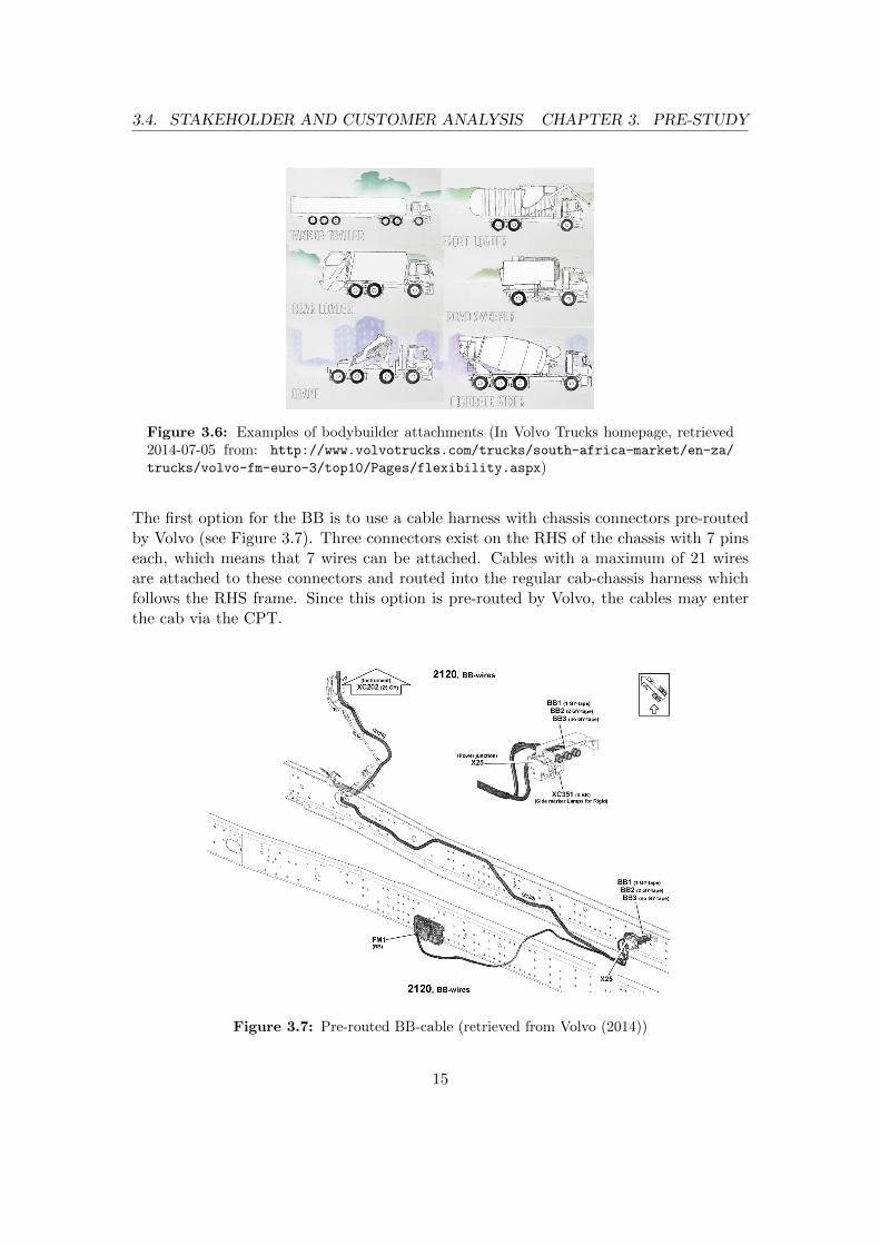
There are usually 3 kinds of people involved in a truck deal; a customer, a truck manufac-turer salesman and a bodybuilder (henceforth called BB). A customer visits a salesmanof the chosen truck brand and expresses the intended use of the desired truck. The sales-man compiles these needs and sets up an order which is relayed to the manufacturingdepartment of the truck manufacturer starting the production of the truck. The purposeof a truck is usually fulfilled by auxiliary attachments which are provided by the BB afterthe truck has been produced. Examples of such auxiliary attachments (see Figure 3.6)could be cranes, concrete mixers, rear loaders and more. Even smaller attachments suchas lamps can be installed by a BB. This thesis focuses on the larger attachments situ-ated on the chassis behind the cab. These attachments are mechanically and electricallyintegrated with the truck.
The BB’s cabling also needs to be routed into the cab. In Volvo’s trucks the BBs routetheir cables to the BB’s electrical central, a separate entity provided exclusively for BBby Volvo.
Current BB-Routing
Since the CPT is only meant to contain the cables which are routed by Volvo, two dif-ferent options are offered for the BBs to route the cables from the attachments to theinside of the cab.
14
3.4. STAKEHOLDER AND CUSTOMER ANALYSIS CHAPTER 3. PRE-STUDY
Figure 3.6: Examples of bodybuilder attachments (In Volvo Trucks homepage, retrieved2014-07-05 from: http://www.volvotrucks.com/trucks/south-africa-market/en-za/
trucks/volvo-fm-euro-3/top10/Pages/flexibility.aspx)
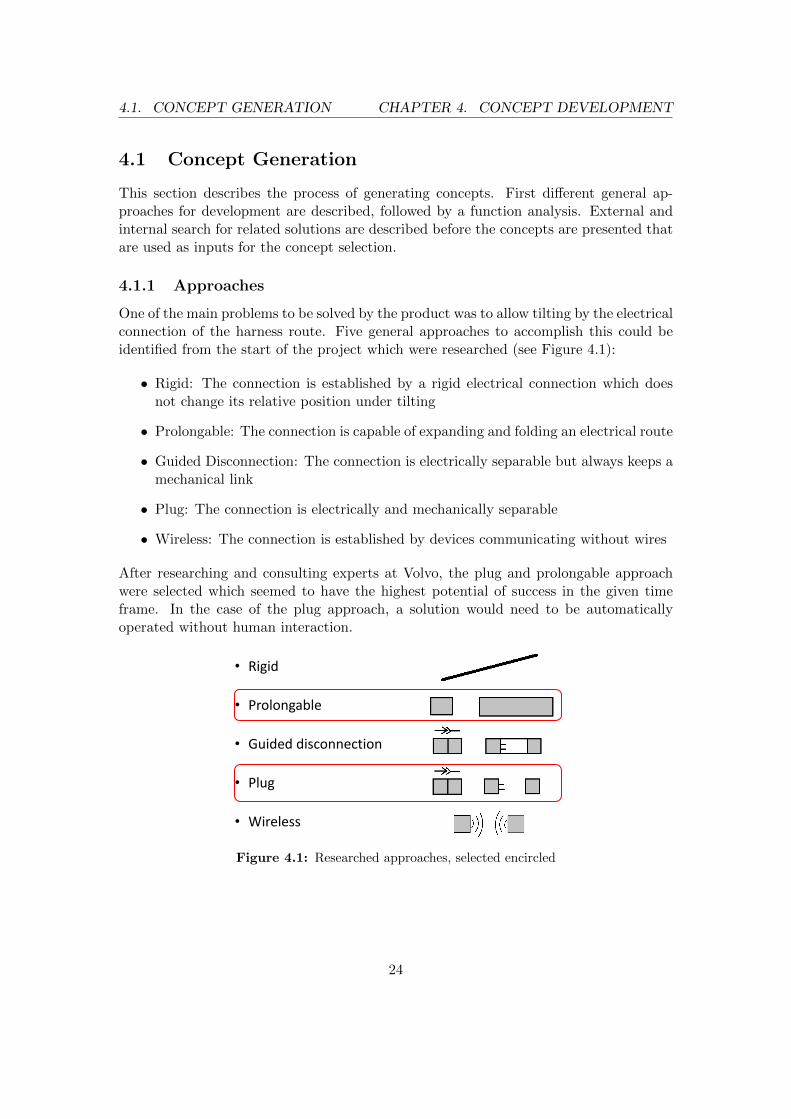
The first option for the BB is to use a cable harness with chassis connectors pre-routedby Volvo (see Figure 3.7). Three connectors exist on the RHS of the chassis with 7 pinseach, which means that 7 wires can be attached. Cables with a maximum of 21 wiresare attached to these connectors and routed into the regular cab-chassis harness whichfollows the RHS frame. Since this option is pre-routed by Volvo, the cables may enterthe cab via the CPT.
Figure 3.7: Pre-routed BB-cable (retrieved from Volvo (2014))
15

3.4. STAKEHOLDER AND CUSTOMER ANALYSIS CHAPTER 3. PRE-STUDY
The second option for the BB is to route their own cables by themselves. As with theprevious option the cables are routed along the RHS frame together with Volvo’s harness.In order to clamp the cables together with the harness, old cable ties have to be removedand replaced with new ones at the same location. The BB may use grommets made ofrubber instead of the CPT to enter the cab. The grommets cover up openings in thecab wall where the BB-wires can pass through. Located close to the CPT, the grommetsseal the openings at the front of the truck (see Figure 3.8a). When the truck is deliveredto the BB the grommets are completely sealed. The BB has to cut open rubber busheson the grommets at the correct height in order for the wires to fit and pass through (seeFigure 3.8b).
(a) Position on the front (retrieved fromVolvo (2014))
(b) Instructions of use (retrievedfrom Volvo (2014))
Figure 3.8: Grommets
BB Study Visit
To gather more knowledge about BBs and how they route their cables today, a studyvisit was arranged at the BB JOAB. The study visit included interviews with a seniortechnical adviser and a tour in the workshop. In the workshop the installation of attach-ments could be observed and the installation personnel was ready to answer questions.The results of the study visit are presented in the following.
As observed at the BB, the trucks are not prepared for the BB when they arrive fromthe truck manufacturer. There exists no predefined procedure of cable routing. Sinceeach truck is usually customised, it is often not possible for the BB to use cables whichare separately provided by the truck manufacturers. Instead the BB needs to designtheir own cables. The BB does not make new holes in the cab body and therefore usesonly the available pass-through or grommets to enter the cab.
16

3.4. STAKEHOLDER AND CUSTOMER ANALYSIS CHAPTER 3. PRE-STUDY
The communication between the BB and the truck manufacturers seems to be inefficientin certain aspects. The truck manufacturers provide an instruction manual informingthe BB about the proper procedures during bodybuilding operations. The BB admitsthough to not fully consider the provided instructions. The BB follows the regulationshe is aware of, but the instruction manual does not seem to convey the information asintended. The BB does not have a lot of possibilities to affect truck manufacturers sincehe is not involved until late in the design phase. Information about new trucks are notusually disclosed to the BB until the final release of the truck.
The BB starts the routing from inside the cab and continues the route towards the chas-sis. Inside the cab all the switches on the dashboard are installed and the cables arerouted from the electrical central to their respective pass-through or grommet. This isone of the most difficult tasks for the BB as it often interferes with the interior whichneeds to be torn out and reinstalled later. The visited BB handled only the installationof the cabling which had been delivered pre-assembled by their suppliers with a connec-tor fixed at one end. The other end was free in order to thread it through cavities wherethe cabling should be routed. The attachment to be installed was also delivered fullyprepared with the cabling. Basically the BB routed the cables from inside the cab toan interface on the chassis. The attachment was then lifted onto the truck and installedboth electrically via the interface and mechanically onto the frame.
(a) CPT with the pre-routed BB-cablesencircled
(b) Incorrect use of grommet where too manyBB-wires pass through
Figure 3.9: BB-routing in practice
During the study visit one Volvo truck was examined with the pre-routed BB-harness(see Figure 3.9a). The BB however chose not to use the pre-route as he considered thenumber of pins to be insufficient. The BB could have used the existing 21 pins butneeded to route the remaining wires anyway which made it more convenient for the BBto route all wires together at once to the front. The BB thought that the pre-route wouldmaybe prove useful in the future if the customer would decide to add more attachments.In general, the BB considers 20-30 pins to be enough for most trucks and the BB believes
17

3.4. STAKEHOLDER AND CUSTOMER ANALYSIS CHAPTER 3. PRE-STUDY
that this number will not change considerably in the near future. In the front it was seenthat the BB used the provided grommets incorrectly to enter the cab. The grommet hadbeen cut open too much and more wires than intended by Volvo were passed throughit. This resulted in a grommet which could not properly seal the inside of the cab fromdirt and water (see Figure 3.9b).
From the study visit the following problems with the BB-harness routing were identified:
• The number of pins on Volvo’s pre-routed connectors are not enough
• The cab entry provided by Volvo’s grommets are not large enough
• Instructions provided by truck manufacturers are not fully conveyed
The decision was taken to develop solutions aimed for the BB-cables in order to solvethese existing problems. The idea was to develop solutions which promote the BB-routingby facilitating the routing for the BBs, instead of instructing or restricting them. Thispossibility would also create more space for other cables and at the same time decreasethe BB’s impact of the Volvo’s own routing.
3.4.2 Aftermarket Service
In order to capture information from the aftermarket service department at Volvo, sev-eral interviews were conducted. Most of the time the authors let the interviewee talkfreely and occasionally posed appropriate follow-up questions in addition to the preparedquestions. The focus was to gain information about the maintenance of the electricalequipment, their needs and problems and how aftermarket service would be affected bya new harness routing and pass-through solution.
Trucks are usually scheduled for maintenance 1-2 times per year after every 100 000 km.Trucks which are bought by a logistics company are usually contracted for 5 years ofmaintenance. The lifetime of a truck is considered to be 7-8 years but it is not uncom-mon that the truck is used up to 10 years. (Volvo, 2014)
In order to identify and repair problems with the truck it is necessary for the aftermarketmaintenance to diagnose the truck. This is done by connecting measuring equipmentinto the truck’s electric circuit. The principle behind diagnosis is to search for errors firston a system-wide level and then narrow it down to the component level. The malfunc-tioning component does not need to be the source of the error in which case aftermarketservice starts tracing for the source along the circuit. Often, connectors are a possiblesource of the error. The two nodes of the measuring equipment are coupled into thetruck’s electric circuit. If the equipment senses a fault, an error exists in the componentsbetween the nodes. For the equipment to be able to diagnose, the whole electric circuitmust be closed. (Volvo, 2014)
18

3.5. SYSTEM POSITION ANALYSIS CHAPTER 3. PRE-STUDY
During maintenance, the cab is tilted in order to access the engine. Therefore, one mainconcern for the aftermarket service is to have easy access to the engine to be able toinspect, reach and use their equipment. Diagnosis should not be obstructed by a newsolution for the pass-through. In certain situations it is important to be able to diagnoseand at the same time access the engine. After the error has been discovered, the nec-essary parts are replaced. During replacement the diagnostic equipment does not needto be connected. Volvo’s aftermarket service usually only diagnoses Volvo’s own cables,but since the BB cabling is interconnected with Volvo’s components the BB cabling isstill important for the diagnosis process. (Volvo, 2014)
From the analysis it became apparent that the focused BB cabling does not have tobe coupled under a standard tilting operation. Under certain circumstances the BBcabling needs though to be a closed circuit for error search purposes. With the gainedinformation a worst-case number of tilting operations was set to 200 on the Europeanmarket. Error searching does not take place every time the cab is tilted but can berelated to the maintenance interval discussed above. It is not possible to give a generalestimation about the number of times the BB cabling has to be coupled for error searchpurposes during a tilted state of the cab.
3.5 System Position Analysis
Positioning of a new pass-through solution on the cab and chassis was split up into twomain parts; a connection point and a pass-through point. The connection point is thepoint on the cab where the cabling route from the chassis first touches the cab in a lockedposition. The pass-through point is where the cabling is physically entering the inside ofthe cab. These two points may be the same physical point but they do not have to be.
Figure 3.10: Target truck
19

3.5. SYSTEM POSITION ANALYSIS CHAPTER 3. PRE-STUDY
Simplified, the cab can be seen as a cube. A picture of the chosen target truck in Figure3.10 may demonstrate this. Thus it has 6 possible planes for connection and pass-throughpoints for a route from the chassis; front, left and right side, top, floor and back. Thefront is equipped with a component called firewall which adds protection for the driverin case of a fire. The firewall and special safety regulations put strict requirements onthe pass-through in the front. Originating from the front, a routing close to the centreof rotation during tilting may lead to minimal cable movement. The left and right sideplanes offer possible connection points but they are difficult to reach from the chassisstructure due to their remote position. Furthermore, the sides perform potentially largermovements under driving as they are situated furthest from the middle of the truck. Thesides do not offer possible pass-through points into the cab as minimal space is available.A pass-through point on the sides of the cab would furthermore lead to asymmetry andthus an aesthetically unpleasant appearance of the truck. Protruding structures at thesides of the cab will also affect the aerodynamic properties. The top does not seem like asound option for placing a connection point since it is geometrically the most distant partof the cab with respect to the chassis. The top can offer pass-through points, yet withlimitations as aerodynamics and aesthetics prohibit certain positions. The floor and theback of the cab seemed to offer large areas for both connection and pass-through pointsand are furthermore situated in direct proximity to the chassis in the locked position.This is why the investigation was focused on these two areas.
The space on the back of the target truck is restricted by the envelope of all the possiblepositions of a trailer behind the cab wall. This envelope is called the trailer sweep (seeFigure 3.11) and has its minimum distance from the cab wall in the centre of the truckin Y-direction and at the top of the back wall in Z-direction. All components on thetruck shall keep a certain safety distance from the trailer sweep.
Discussions with Volvo employees and investigation of the target truck have shown thatthe back of the cab is more suitable for a connection point than the floor. The followingguided the decision to chose the back plane as a location for the cab connection point:
• The movement of take-off and landing is more controlled at the back as the lockingmechanism is situated in the corner between cab floor and cab back
• Space is very limited underneath the cab floor in the locked position
• Temperature conditions are worse under the cab floor than on the back
• The environment is harsher under the cab floor as it is more exposed to dirt andwater
The placement of the pass-through point does not have to be on the same plane as theconnection point. A placement in the same plane might though make mounting easierand could allow for further integration of the product in the future.
20

3.5. SYSTEM POSITION ANALYSIS CHAPTER 3. PRE-STUDY
Figure 3.11: Envelope of the trailer sweep on a truck model
Detailed placement of the new product on the chosen plane had to be decided in orderto start developing the product, however the choice of placement is in itself dependenton the product design. These two design parameters find themselves in a implicit de-pendency relationship. To break out of this paradox it was decided to begin with thedevelopment of the product which led to input for the positioning. This in turn rein-forced the development of the product and the iteration process was followed until thefinal design was reached.
21


4Concept Development
This chapter gives an account of the development process of the concepts. First, theearly phase of generating concepts is described which reflects the procedure of creatingideas from scratch. Afterwards the selection process of the concepts is described. Finallythe prototyping and testing of concepts is explained.
23
4.1. CONCEPT GENERATION CHAPTER 4. CONCEPT DEVELOPMENT
4.1 Concept Generation
This section describes the process of generating concepts. First different general ap-proaches for development are described, followed by a function analysis. External andinternal search for related solutions are described before the concepts are presented thatare used as inputs for the concept selection.
4.1.1 Approaches
One of the main problems to be solved by the product was to allow tilting by the electricalconnection of the harness route. Five general approaches to accomplish this could beidentified from the start of the project which were researched (see Figure 4.1):
• Rigid: The connection is established by a rigid electrical connection which doesnot change its relative position under tilting
• Prolongable: The connection is capable of expanding and folding an electrical route
• Guided Disconnection: The connection is electrically separable but always keeps amechanical link
• Plug: The connection is electrically and mechanically separable
• Wireless: The connection is established by devices communicating without wires
After researching and consulting experts at Volvo, the plug and prolongable approachwere selected which seemed to have the highest potential of success in the given timeframe. In the case of the plug approach, a solution would need to be automaticallyoperated without human interaction.
• Rigid
• Prolongable
• Guided disconnection
• Plug
• Wireless
Figure 4.1: Researched approaches, selected encircled
24

4.1. CONCEPT GENERATION CHAPTER 4. CONCEPT DEVELOPMENT
4.1.2 Function Tree
The function tree was established according to the guidelines in Ulrich and Eppinger(2012). The top function was identified to be Provide Routing Architecture forBB. Below this top function three main functions could be identified which were Pro-vide Routing Possibility, Allow Driving Situations and Allow Tilting (see Figure4.3). One of the main functions, Allow Tilting, was identified to be especially important.Therefore, Allow Tilting was assigned to be the critical function which should be devel-oped first. Failing in doing so was assumed to not lead to any success of the developmentproject. Provide Routing Possibility and Allow Driving Situations were assigned to bethe secondary main functions which were to be focused on after the critical functionhad been assessed. The relationship between these main functions may also be depictedas in Figure 4.2 where the critical main function can be seen as the core of the newharness route. Without this core, the surrounding functions cannot be fulfilled. Bothcomplete function trees of the two approaches, plug and prolongable, are very similar(see Appendix B.2). The secondary main functions are identical for both function trees.
Allow Tilting
Provide Route
Allow Driving Situations
Figure 4.2: Relationships between main functions
Provide Routing Architecture for BB
Provide Routing
Possibility
Allow Inclination
Allow Driving Situations
Allow ReclinationProvide BBPT
Provide Routing Points
Provide Transfer Points
Allow Cab-Chassis
Movement
Withstand Vibrations
Unfold Mechanical
Link
Unfold Electrical
Connection
Fold Electrical
Connection
Fold Mechanical
Link
Shelter Electrical
Connection
Shelter Mechanical
Link
Allow Tilting
Fold over Corner
Figure 4.3: Top of function tree
Critical Function
The critical function Allow Tilting is composed by two subfunctions which are AllowInclination and Allow Reclination, which holds true for both approaches (see AppendixB.2). Starting off with the prolongable approach, Allow Inclination indicates means
25

4.1. CONCEPT GENERATION CHAPTER 4. CONCEPT DEVELOPMENT
of extending its reach by unfolding its electrical connection and mechanical link whileavoiding sharp corners. Allow Reclination can be seen as the reverse of Allow Inclinationwith the additional feature to shelter the electrical connection and the mechanical link.
For the Plug approach, Allow Inclination indicates the unmating of the plug and protec-tion of the electrical contacts. The process of unmating the plug can be further dividedinto the acts of releasing the fixation and the electrical contact and how the loose plugis handled. Allow Reclination contains similarly two subfunctions which are Unpro-tect Electrical Contacts and Mate Plug. The mating can also be further divided intosubfunctions describing how the plug is guided on its path, how the final flush and elec-trical connection are established, how the fixation is undertaken and how the pluggingis protected.
Secondary Main Functions
The secondary main functions are composed by Provide Routing Possibility and AllowDriving Situations for both approaches (see Appendix B.2). Provide Routing Possibilityis divided further into three subfunctions which determine how the BB cables are passedthrough the cab-wall and how routing and transfer points are provided. Allow DrivingSituations is composed of two subfunctions, namely the means of allowing the movementbetween cab and chassis and how vibrations are withstood.
4.1.3 External Research
The external research was conducted as advised in Ulrich and Eppinger (2012). One ofthe results from the pre-study was the insight that no other competitor had fundamen-tally different solutions regarding the harness routing and pass-through. Therefore, themain effort was put into researching similar technologies in other industries and appli-cations than the truck industry.
For the plug approach the research was focused on technologies which were associatedwith a number of connections and disconnections of different kinds of contacts, preferablyautomatic. Most insight could be gained from technologies containing electrical connec-tions, but also from other connections such as hydraulic and mechanical connections.Notable examples of industries were the train industry with its mechanical connectionsbetween waggons and aerospace industry with its automatic guiding of in-flight refu-elling and space docking systems. Furthermore, other applications and areas within thetruck industry were used as an inspiration, e.g. the fully automated fifth-wheel trailercoupling by JOST (see Figure 4.4). For the prolongable approach the research was fo-cused on mechanisms which extended over a gap by folding and unfolding. Examplesof interesting technologies were different cable drums and collapsible bridges (see Figure4.5).
26

4.1. CONCEPT GENERATION CHAPTER 4. CONCEPT DEVELOPMENT
(a) Trailer mounted interface (b) Truck mounted interface
Figure 4.4: JOST KKS2 trailer coupling interface (retrieved 2014-08-06 from http://
www.youtube.com/watch?v=V8TKFr3CzDA at positions 0:42 and 0:54)
Figure 4.5: The Rolling Bridge in London, example of a collapsible bridge.(in Wikimedia Commons, the free media repository, Retrieved 2014-08-08 from:http://commons.wikimedia.org/wiki/File:The_Rolling_Bridge_by_Thomas
_Heatherwick,_Paddington_Basin2.jpg)
4.1.4 Brainstorming
The brainstorming consisted of both, individual sessions by the authors and group ses-sions with invited persons from Volvo. For the individual brainstorming sessions theauthors first generated and prepared concepts by themselves followed by a mutual ideaexchange on a whiteboard (see Figure 4.6). In this way the authors kept themselvesupdated about each other’s ideas which could be further developed by discussion
There were two group brainstorming sessions with two different groups which were fo-cused on answering the question How can the electrical connection allow cab movement?.As previously described in section 2.5 the brainstorming events were divided into twoparts, one more structured part comprised of the 6-3-5 brainwriting method and onemore unrestricted part comprised of the mind mapping method. The authors chose theparticipants and divided them into groups with compatible individuals. A mix of the-oretical and practical knowledge was desired in both groups. There was an apparentdifference between the two group sessions with regards to the two methods. One group
27

4.1. CONCEPT GENERATION CHAPTER 4. CONCEPT DEVELOPMENT
Figure 4.6: Example of the authors’ individual brainstorming event
was much more responsive in the structured part than the other which in turn performedbetter in the unrestricted part. The aim was to have groups of about six people in eachgroup. Due to cancellations the first group consisted of two and the second of five mem-bers. In the first group the authors had to participate in the brainwriting method toproduce valuable results. The 6-3-5 method was thus adapted accordingly to the numberof participants present at each session. Similarly the mind mapping had to be adjustedfor each group, since the authors needed to be more or less involved in order to provokerespective group answering. In combination with the methaphoric story representing thedifficulty of separating contacts abstractly (see Appendix B.3), a slideshow of stimulatingpictures was shown to provoke associations.
4.1.5 Function-Function-Solution Tree
Starting from the input gained from the external research and brainstorming events,many ideas were generated. Each of these ideas were analysed and categorised withrespect to the function tree in order to create a function-function-solution tree where onlysolutions to the lower level functions entered. Each solution was described with a shorttext, sometimes also together with a picture. The idea was to gather as many possiblesolution for each of the lower level functions. After a pre-screening (see section 4.2.1),the solutions were assembled into concepts for the main functions by using combinationtables. As previously described the focus of these first concepts was to fulfil the criticalfunction Allow Tilting.
28

4.2. CONCEPT SELECTION CHAPTER 4. CONCEPT DEVELOPMENT
4.2 Concept Selection
This section describes how the selection between different concepts for the critical func-tion was carried out. Concepts of the same approach were evaluated with respect toeach other in order to maintain concept diversity. A pre-screening was conducted beforeconcepts for the main functions could be created. The concepts were then evaluated afterfactors based on information gathered during the pre-study phase. Concept screeningwas performed for both approaches and concept scoring was used whenever the conceptscreening was not enough to elicit the superior concepts. The screening and scoringmatrices can be viewed in Appendix B.4.
4.2.1 Pre-Screening
Prior to creating concepts satisfying the main functions, the most irrational solutions forlower level functions were cancelled out by a pre-screening to lower number of possiblecombinations. By combining the remaining solutions, concepts for the main functionswere created which entered the selection process of screening and scoring.
4.2.2 Feedback
To assist the evaluation process of the concepts, a presentation was held at Volvo inorder to capture comments, thoughts and criticism. In this way both Volvo’s and theauthors’ expectations and goals could be matched. Furthermore, the concepts’ successprobability could be evaluated.
4.2.3 Concept Screening
Concept Screening with a Pugh-matrix was performed as recommended in Ulrich andEppinger (2012). It was performed twice for both the plug and pronlongable approachin order to secure a non-biased result. The datum concept was changed once in thescreening of each approach. For the plug concept, it became apparent that the conceptcalled Selfie was superior to the others. The outcome of the prolongable concepts wasmore ambiguous and a concept scoring had to be performed in order to choose a winningconcept.
It follows a list of the concepts that were evaluated during concept screening, brieflydescribed in order to allow the reader to follow the selection process. A more detaileddescription of the final concepts will be presented later.
29

4.2. CONCEPT SELECTION CHAPTER 4. CONCEPT DEVELOPMENT
Plug Concepts:
Figure 4.7: Press
Press: A plug is loosely fixed to an interfacewhich holds the plug in position. The con-nection closes by pulling the plug towardsthe back of the cab with a third part actinglike a press. The interface of the electricalcontacts is facing towards the back of thecab. The closing and opening of the Pressis operated by rods on a fork which hold theplug. The rods interact with gears inside thePress which operates a screw that pushes thepress together.
Figure 4.8: Inverted Press
Inverted Press: The Inverted Press alsouses a third part which pushes the plug intoan interface on the cab wall, like in the regu-lar press concept. The Inverted Press seeksto remain in the closed state. The closingforce is provided by a gas spring. The pressis opened by a fork that enters the receivingcylinders of the press. The fork is comprisedof tapered rods that activate a mechanismduring sliding. In the first section of therod the press is opened and the plug is pre-inserted. In the second section of the rodthe press closes itself and mates the plug.
Figure 4.9: Yoyo
Yoyo: The plug is retracted to its matinghousing by a rope which is under tension andseeks to mate with the plug. Due to the ropetension the plug is always oriented towardsits mating interface during the reclinationprocess.
30

4.2. CONCEPT SELECTION CHAPTER 4. CONCEPT DEVELOPMENT
Figure 4.10: Search and Engage
Search and Engage: A plug is guided byextensions on its sides which are connectedto a fork of rods which holds the plug up.A shell on the cab wall guides the extensionof the plug towards the mating point. Atthe final mating point the rods of the forkactivate a closing mechanism by rack andpinion which pushes the plug towards themating at the back wall.
Selfie: A plug which is mated in landing direction. The concept comprises a fully au-tomatic coupling that is independent of human interactions. Pictures cannot be shown.
Prolongable Concepts:
Figure 4.11: Pulley System
Pulley System: The overlength of the elec-tric cables are enough to bridge the gap be-tween chassis and cab during tilting. Whenthe cab is locked the overlength is stored se-curely inside a shell. The retraction of thecables is performed by a pulley inspired sys-tem in which the cables are routed through.The Pulley system is situated at the back ofthe cab.
Figure 4.12: Mid-Air Reel
Mid-Air Reel: The Mid-Air Reel rolls upthe cabling between chassis and cab from themiddle of the connection. The reel rolls upthe cabling towards the cab at the same timeas it rolls up the cabling towards the chas-sis. The two reels have a different roll-updirection. In the tilted state the reel hangsin mid-air in the cable connection betweencab and chassis.
31

4.2. CONCEPT SELECTION CHAPTER 4. CONCEPT DEVELOPMENT
Figure 4.13: Tubic Spiral
Tubic Spiral: A telescopic cylinder bridgesthe gap between chassis and cab during tilt-ing. The spiral cables reside inside the cylin-der which folds during declination. Rota-tional joints at each end of the cylinder al-lows the rotational movement of the cab (x-and y-axis).
Figure 4.14: Double Reel
Double Reel: The Double Reel rolls up theentire necessary overlength of the cable largecable reel. It has a reel with a smaller diam-eter attached to its back which is facing thecab. On the smaller reel, less cable lengthis rolled up and thus the cabling can hangdown in a closed compartment at the backof the cab when unreeled. To save the ca-ble from forces an unspecified cable carrieris used to accept all the pulling forces.
Figure 4.15: Lampy
Lampy: The mechanism of a balanced lampis used to provide a foldable, force-free link-age between the chassis and the cab. Thearms are surrounded by clothes to protectthe linkage.
32

4.2. CONCEPT SELECTION CHAPTER 4. CONCEPT DEVELOPMENT
Figure 4.16: Scissor Lift
Scissor Lift: The cable resides inside astructure which unfolds through a panto-graph mechanism. The mechanism folds ina zigzag pattern and the cables are foldedtogether inside the pantograph. The cablesare winded like in conventional scissor lifts,to increase the number of fixation points forthe cables a channel is situated inside thedouble pantograph.
4.2.4 Concept Scoring
Concept Scoring was performed as recommended in Ulrich and Eppinger (2012). Withweighted factors in accordance to their importance the concept scoring made a notice-able difference between the different Prolongable concepts. The winning concept wasthe Scissor Lift. This concept was further developed into PseudoPanto.
The positive ideas behind the losing concepts were not lost in either of the concept screen-ing or scoring phases. By merging outstanding aspects of ideas from losing concepts withthe winning concepts, valuable inspiration could be used in the concept developmentphase.
33

4.3. PROTOTYPING CHAPTER 4. CONCEPT DEVELOPMENT
4.3 Prototyping
The development of the chosen concepts was carried out in two development loops. Thefirst loop ended in the production of a physical real-size prototype. The chosen conceptsthus had to be developed and prepared in CAD in the first loop to a certain level whichallowed prototyping. Thus all joints and interfaces of the concepts had to be set in away that ensured their functioning. Details such as chamfers or fillets could be omitted.Furthermore, manufacturing aspects were not in focus for the prototype development.The prototypes were tested on a full-size cab-chassis rig. Analysis of the test resultsrevealed design weaknesses which initiated a re-design which ultimately led to the finalconcepts described in chapter 5.
4.3.1 Prototype Manufacturing
In total there were two prototypes produced, one for each chosen concept. Some finishingwork of the prototypes was necessary in order for them to function properly becausethe SLS process added more material than specified. Mostly the work consisted ofgrinding, drilling, threading holes and colouring parts. The necessary manual work on theprototypes showed clearly the importance of tolerances for certain parts. Subsequently,the design was adapted to incorporate fewer area contact interfaces and thus fewerspecified tolerances.
4.3.2 Assembly
The authors assembled the manufactured prototype together with standard parts suchas washers and screws into full prototypes themselves. Through this process even moreinformation regarding the construction was gained and at the same time the possibilityof incorrect assembly was reduced. In certain cases the assembly process was observedto be tedious due to a considerable amount of repetitive operations where parts couldeasily be misplaced.
4.3.3 Prototype Testing
The actual testing was performed on a full-size cab-chassis rig inside a workshop. Thephysical verification of the critical Allow Tilting function was preferred over a computersimulated verification, due to lower time requirements and increased level of validity.Furthermore, the mounting position of the product on the cab and chassis was evaluated.
The test consisted of one tilting operation (locked position to tilted mode and back again)where the behaviour of the respective concept was observed. The level of deflections ofcertain parts was documented by notes, pictures and video recording. Subsequently, adamage assessment of the concepts was performed. The documentation of the prototypetesting contributed considerably to the following re-design loops. The videos proved tobe especially useful as they enabled reviewing of the test over and over again.
34

5Final Concepts
This chapter describes the final concepts that have been developed in the course of thisthesis. In summary the development has yielded a solution for the alternative harnessroute that routes the BB cables from the chassis to the bottom edge of the cab’s backwall and along the cab floor where they are passed through into the cab. The new pass-through for the cabling may be easily accessed and offers furthermore the possibilityto connect cabling from cab-fixed BB components on the cab directly to the new pass-through. The critical part of the route which needs to handle the tilting gap betweenthe chassis and the cab’s back wall is solved by two alternative solutions; a prolongationand a disconnection of the route.
In the following, first the concept which satisfies the function Provide Route is presented.Then, the two alternative concepts for the function Allow Tilting are presented, one forthe prolongation approach called PseudoPanto and one for the disconnection approachcalled Selfie.
35

5.1. NEW ROUTE AND PASS-THROUGH CHAPTER 5. FINAL CONCEPTS
5.1 New Route and Pass-Through
This section describes the concept to solve the secondary main function Provide Route.Developing a solution for this function has not been the main focus of the thesis, howeverit was still done to be able to provide a holistic solution for the product. The developmentresulted in a new cab pass-through (CPT) and in a new component called Routeway.The final development stage for these parts is described here.
5.1.1 New CPT
The new CPT was designed after the current one which is in use in the front of the trucksince its design seemed robust and well-proven. The placement for the new CPT waschosen to be on the right cab floor in the area underneath the passenger seat. The newCPT is composed of three main parts which can be seen in Figure 5.1:
• An inner part (purple) is in contact with the cab floor on the inside of the cab
• A middle part (beige) is in contact with the cab floor on the outside of the cab
• An outer part (dark brown) seals and protects the middle part and can easily beremoved
Figure 5.1: New CPT
The inner part has four holes in its corners which are used to fix it with screws throughthe cab floor to the middle part. Furthermore, the inner part features three rectangu-lar holes where electrical connectors from both the inside and the outside route can beplaced in.
The middle part provides holes for the fixture towards the inner part as well as for thefixture towards the outer part. The middle part also features the upper halves of threeholes for corrugated hoses which should be used for harnessing the wires on the cab body.
36

5.1. NEW ROUTE AND PASS-THROUGH CHAPTER 5. FINAL CONCEPTS
The outer part seals the middle part by its geometry and tight fit towards it (see Figure5.2). Furthermore, the outer part exhibits the lower halves of the three holes for corru-gated hoses. Together with the middle part, a corrugated hose is clamped tightly in theholes which offer three sealing lips (see Figure 5.3).
Figure 5.2: Cut through new CPT
Figure 5.3: Holes for corrugated hose on the new CPT
The position of the new CPT was chosen to be on the cab floor because more spacewas seen to be available there than on the cab’s back wall. On the back wall a lotof components and the envelope of the trailer sweep could interfere with the CPT.Furthermore, the CPT was seen to be more exposed to the environment on the back wallthan in the sheltered space underneath the passenger seat. A further consideration wasVolvo’s fire safety requirements which demand that a specified fire of a certain componenton the outside of the cab must not reach the inside of the cab after a specified amount ofminutes (see Appendix A.1 for the requirements). The chosen position for the new CPThas the same requirements for fire safety as the current positioning. The cab’s back wallhas higher requirements in some parts which might be difficult to meet.
37

5.1. NEW ROUTE AND PASS-THROUGH CHAPTER 5. FINAL CONCEPTS
5.1.2 Routeway
The Routeway is placed underneath the cab floor and extends from the cab’s back wallto the new CPT (see Figure 5.4). This concept embodies a different paradigm towardscable routing than the traditional one. It aims to create space for routing cables insteadof routing cables where space is found. The Routeway consists of the following parts:
• A back fastener (dark brown)
• Four flat elements in connection to each other (yellow, pink and green)
Figure 5.4
The back fastener rests on the bottom fold of the cab’s back wall and can be fixed to-wards the wall by a screw through the fastener’s hole. At its back the fastener features anopening where the first flat element of the Routeway can be hooked into (see Figure 5.5).
The flat elements consist of three different but similar parts; a large one in the back,two identical ones in the middle and a small one in the front towards the CPT. Allflat elements have loop anchors attached to their tops which fit into the cross beamsunderneath the right cab floor. The cross beams have holes where the anchors can bebolted to. The flat elements are connected by simple sliding joints to each other (see
38

5.1. NEW ROUTE AND PASS-THROUGH CHAPTER 5. FINAL CONCEPTS
Figure 5.5: Back fastener of Routeway Figure 5.6: Joint between Routeway ele-ments
Figure 5.6). All flat elements feature a raster of elongated slots which serve as mountingpossibilities for cable straps which fix a harnessed route towards the Routeway. The largeflat element in the back is curved to avoid clash with a storage box in this position. Thesmall flat element in the front is slightly bent upwards to allow a smooth routing towardsthe entry holes of the new CPT. The middle elements are simple straight elements.
5.1.3 Further Development
Since the focus of the development was not put on the described parts, they need con-siderable improvement before they reach a mature state. The new CPT and Routewayare pure concepts which have not been prototyped or tested. The design of both needsfurther refinement before prototypes can be built.
The new CPT needs an adaptation of its surfaces towards the slightly bent surface of thecab floor, the current model only features straight lines and forms. To ensure good seal-ing also gaskets need to be chosen and integrated in the design. The material of the newCPT has not been chosen but can be assumed to be of the same type as the current CPT.
The Routeway needs evaluation on the possibility of downscaling it to absolute necessarydimensions. The distance between the fixture slots may also be readapted to reach anoptimal design. Furthermore, it should be assessed whether physical connections betweenthe single elements are needed or can be omitted. These measures should lead to materialsavings and a more minimalistic and cost effective design. The material itself needs to bechosen in a further step. Testing with prototypes should examine vibration behaviour ofthe entire structure during standard driving situations since high vibration amplitudescould damage the routed cabling.
39

5.2. PSEUDOPANTO CHAPTER 5. FINAL CONCEPTS
5.2 PseudoPanto
This chapter describes the final development stage of the concept chosen under theprolongable approach, called PseudoPanto. After a description of the general idea atheoretical background about the working principle will be given first, followed by adetailed description of the different parts of the concept. Subsequently, insights fromthe prototyping and testing will be described and reasons for engineering changes thatled to the final concept will be illuminated. Finally, an evaluation of possible materialselection for the product will be given.
5.2.1 General Idea
The PseudoPanto builds on two general ideas. First, the idea of folding and unfoldinga mechanical link between cab and chassis with the mechanics of a scissor lift, alsocalled a pantograph. The main advantage of a pantograph is its ability to fold mostof its maximum length from the extended state into its width in the folded state. Thesecond idea is to harness wires inside a cable channel that protects it from the harshenvironment at the back of a truck. The pantograph is used for the mechanical guidingof the prolongable structure. Its characteristics and prolongation movement are analysedin section 5.2.2. To the central axis of the pantograph, 9 cable channels are fixed, 7 longones in the middle part and 2 short ones in the ends. The channels are fixed in the middleof their back wall rotationally free. The cable channels are meant to guide the wires ina zigzag form over the length of the prolongation. The cable channels are connected intheir corners by hinges which restrict and guide the channels in their motion. Since thezigzag form of the cable channels resembles a half pantograph but does not fully behavelike a pantograph, its motion can be seen as pseudo-pantographic from which the nameof the concept derives.
5.2.2 Pantograph Analysis
The general properties of pantographs in use in this concept are analysed in this section.The pantographic structures are classified first to be able to describe them with a com-mon vocabulary. Then, the kinematics of pantographic motions and the static forces inthe structure are analysed. Finally, the necessary lengths of the structure are evaluated.
Classification
Pantographs have been categorised in this report to get an overview of the different vari-ants. The ones treated here have been defined as symmetric pantographs. This meansthat all of the arms (rigid, smallest entities) of a pantograph have two rotational jointsin their extremities and one rotational joint in the middle of the connection line betweenthe joints in the extremities (see Figure 5.7).
A pantographic structure consists of a multiple of single pantographs. A pantographconsists of a number of arms which are holding its structure together by being linked
40

5.2. PSEUDOPANTO CHAPTER 5. FINAL CONCEPTS
Figure 5.7: Symmetric pantograph arm
(a) Left-oriented pantograph (b) Right-oriented pantograph
Figure 5.8: Chirality of pantographs
in all their rotational joints to form a repetitive scissor-like movement. Symmetric pan-tographs can be described by their basic elements since the whole pantograph is just arepetition of these basic elements. The basic element in the symmetric pantographs isthe X-formation of two arms, called scissors in this report. If a single pantograph is putin a plane with its extension direction facing upwards (North) in the plane, then lookingat a basic element in this position reveals the orientation of the scissors and thus thepantograph; if the arm which is lying upon the other arm is pointing to the upper left(North-West), the pantograph is called left-oriented (see Figure 5.8a). If the arm whichis lying upon the other arm is pointing to the upper right (North-East), the pantographis called right-oriented (see Figure 5.8b). Single pantographs are chiral figures, i.e. aleft-oriented pantograph cannot be rotated or translated in any way to become a right-oriented pantograph without disassembling it. This is not true for the basic elementsalone which can easily be rotated around their common joint in the middle to become apart of a left or right oriented pantograph.
A single pantograph can furthermore be distinguished into planar-scissor and offset-scissor pantographs. In a planar-scissor pantograph, the arms of the scissors touch eachother during the pantographic movement (see Figure 5.9). One of the faces of each arm
41

5.2. PSEUDOPANTO CHAPTER 5. FINAL CONCEPTS
Figure 5.9: Planar scissor pantograph Figure 5.10: Offset scissor pantograph
(a) Homogeneous (b) Heterogeneous
Figure 5.11: Double pantographs
thus moves in a common plane. An example for this would be an actual scissor which isused for cutting in daily use. In an offset scissor pantograph no faces of the pantographarms touch each other as they are linked by bridges towards each other (see Figure 5.10).
Single pantographs can furthermore be combined to multiple pantographs. During thisthesis only single and double pantographs were analysed. In a double pantograph twosingle pantographs are linked to each other in parallel with the same extension direc-tion by distancing links (bridges) in at least two rotational joints on their middle axis.Depending on choosing either two pantographs with the same or a different orientation,the double pantographs are either called homogeneous or heterogeneous respectively (see
42

5.2. PSEUDOPANTO CHAPTER 5. FINAL CONCEPTS
Symmetric Pantographic Structures
Single Pantograph Double Pantograph
Left Oriented
Right Oriented
Planar Scissor Homogeneous Heterogeneous Offset Scissor
Left Oriented
Right Oriented
Left Oriented
Right Oriented
Figure 5.12: Classification of pantographs
Figure 5.11a and 5.11b). A comprehensive overview of the pantograph classification isgiven in Figure 5.12.
Motion
A simple analysis of the geometry of a single pantograph is conducted to show its pro-longation properties. The schematic picture in Figure 5.13 of a part of a pantograph isused to analyse the geometric situation in the structure (used variables in Table 5.1).
𝜶
𝒉
𝒘
𝑳
Figure 5.13: Geometrical situation in a pantograph
From Figure 5.13 it follows for a single scissor with two connected half-scissors:
h = L sinα+ 2
(L
2sinα
)(5.1)
w = L cosα (5.2)
Thus it follows for a pantograph with n scissors and two half-scissors in its ends:
h = (n+ 1)L sinα (5.3)
w = L cosα (5.4)
α = arcsin
(h
(n+ 1)L
)(5.5)
43

5.2. PSEUDOPANTO CHAPTER 5. FINAL CONCEPTS
Table 5.1: Variables used for the motion analysis
Variable Description
L Main pantograph arm length
h Height in the pantograph’s extension direction
α Pantographic angle
n Number of basic elements (scissors)
w Width of the pantograph
The relationships show that if the pantographic angle grows with constant angular speed,the height of the pantograph first grows quickly and then the extension speed deceleratesdue to the sinusoidal condition. The pantographic angle in dependence of the extensionh first grows with moderate speed and then grows with an accelerating rate towards theend of the extension. The behaviour can be seen in Figure 5.14a and 5.14b where theextension is manifested by multiples of the arm length L.
0 π/8 π/4 3π/8 π/2
0
5
10
15
Extension in dependence of angle
Pantographic angle
Mu
ltip
licity o
f L
(a) Extension in dependence of angle
0 5 10 15
0
π/8
π/4
3π/8
π/2
Angle in dependence of extension
Multiplicity of L
Pa
nto
gra
ph
ic a
ng
le
(b) Angle in dependence of extension
Figure 5.14: Pantograph geometry analysis
Forces
As the pantograph is intended to be a free moving structure without large forces applied,the following force analysis is kept simple. According to a likely scenario, the followingload case was chosen; the pantograph is fixed in its ends between two points which allowrotation. On each crossing (middle of the scissors) on the pantograph, a force H isapplied (see Figure 5.15). Equilibrium on a pantograph with n scissors leads to:
2F − nH = 0 (5.6)
F =nH
2(5.7)
44

5.2. PSEUDOPANTO CHAPTER 5. FINAL CONCEPTS
𝐹
. . .
. . .
. . .
𝐹
𝐻
𝐻
𝐻
Figure 5.15: Load case of the pantograph
To analyse the crossing arm structure of the pantograph, the structure is cut free in itssingle arms. To analyse the forces in the joints it is sufficient to look on one half ofthe scissors due to the inherent symmetry of symmetric pantographs and the symmetricload case. Thus only one free-cut half of the pantograph is analysed. The half will becalled a “zig-zag” structure. In this structure it is also sufficient to look at one “zig”(arm extending from top left to bottom right) and one “zag” (arm extending from topright to bottom left) to receive the relationships inside the whole structure as it consistsof a repetitive pattern. In the following a zig-arm and a zag-arm are analysed and thegeneral equations derived. The used variables can be seen in Table 5.2.
Table 5.2: Variables used for the force analysis
Variable Description
H External load on each crossing
F Reaction force in ends
S Reaction force in external joints
R Reaction force in crossing joints
n number of scissors
i Index of analysed joint, running top-down
45

5.2. PSEUDOPANTO CHAPTER 5. FINAL CONCEPTS
Equilibrium equations (see Appendix C.2) on a free-cut zig-arm lead to:
Rxi =H
2 tanα− 2Sxi −
2Syitanα
(5.8)
Syi+1 =H
2− Syi (5.9)
Sxi+1 = Sxi +2Syitanα
− H
2 tanα(5.10)
𝑆𝑥𝑖
𝑆𝑦𝑖
𝑅𝑥𝑖
𝑆𝑥𝑖+1
𝑆𝑦𝑖+1
𝐻
2
𝜶
Figure 5.16: Zig-Arm
Equilibrium equations (see Appendix C.2) on a free-cut zag-arm lead to:
Rxi =H
2 tanα− 2Sxi +
2Syitanα
(5.11)
Syi+1 = −H2− Syi (5.12)
Sxi+1 = Sxi −2Syitanα
− H
2 tanα(5.13)
𝑆𝑥𝑖
𝑆𝑦𝑖
𝑅𝑥𝑖
𝑆𝑥𝑖+1
𝑆𝑦𝑖+1
𝐻
2
𝜶
Figure 5.17: Zag-Arm
46

5.2. PSEUDOPANTO CHAPTER 5. FINAL CONCEPTS
The pantograph taken in this example also has a top and a bottom, both resembling half-scissors which are like scissors that end in their common joint. This makes mountingeasier. The static conditions of the top and bottom half-scissors can be derived (seeAppendix C.2) according to Figure 5.18 as:
Sx1 =F
2 tanα(5.14)
Sy1 =F
2(5.15)
𝑆𝑥1
𝑆𝑦1
𝐹
𝑆𝑥1
𝑆𝑦1
𝜶
Figure 5.18: First arm pair
A numerical analysis of all the motion equations was conducted with MATLAB. Theoutput of the analysis can be seen in Appendix C.3. The analysis showed that forcesin the joints increased the further they were situated from the ends of the pantograph.Thus they were greatest in the middle of the structure. Furthermore, the reaction forcesin the crossing joints were seen to be generally higher than the reaction forces in theexternal joints, which could be expected already from the equilibrium equations. Fromthe analysis it could be seen that the reaction forces in the crossings reach a maximumof 100 times the induced load H at an pantographic angle of 20◦. A generic pictureof the force distribution can be seen in Figure 5.19. The crossing joint in the middleof the pantograph will thus guide the design for the other joints. Looking at the totalpantographic structure, the joint reaction forces showed symmetry around an axis in themiddle of the pantograph, parallel to the set truck Y-axis. This could be expected dueto the symmetric properties of the pantograph and due to the symmetry in the load case.
It was also observed that the forces in the joints do not depend on the arm length ofthe pantograph. They solely depend on the number of crossings and the current panto-graphic angle. Forces can reach extreme values when the pantographic angle approacheszero. Such low or high values near 90◦ will though never be reached due to the thicknessof the pantograph arms. The thicker the arms the smaller the sector the pantographicangle can be in.
To exemplify a load case, the MATLAB programme was run assuming 14 crossings. Thecrossing load was assumed to be 1. Due to the linearity in the equations regarding the
47

5.2. PSEUDOPANTO CHAPTER 5. FINAL CONCEPTS
𝑆𝑥
Force
− 𝑅𝑥
Figure 5.19: Force distribution on a generic pantograph
crossing load H, the resulting forces in the analysis can be seen as a multiplicity of H.Thus, resulting loads can easily be scaled up by multiplying with the actual load valuefor H.
Length Analysis
To analyse the minimum needed length for a pantograph to bridge the tilting gap, asimplified model of the target truck was created in the CAD software Catia V5 to repro-duce a tilted position of the truck. The model can be seen in Figure 5.20. The measuresfor the model were taken from Volvo’s actual Catia model of the target truck which hadexact specifications. The main focus in the simplified model was put on the measuresbetween the centre of rotation during tilting and the back of the cab to achieve a ratherexact representation of the tilting operation. On the simplified model a tilt angle of 70◦
was adjusted. The cab lock was taken as a bottom connection point for the bracketholding the bottom of the pantograph (see section 5.2.5). The bracket moves the bot-tom of the pantograph a certain distance away from the back of the cab in the truck’sX-direction. The bottom edge of the back of the cab was taken as the top connectionpoint for the structure which holds the top of the pantograph in the tilted position. Thetop structure also moves the top of the pantograph a bit away from the back wall andthe bottom edge of the back wall. A straight line between the set top and bottom couldbe placed and measured to receive a geometrical minimum length. The top and bottomof the pantograph in the model could also be varied to test different designs and to seewhen clashes would occur.
The resulted geometrical length for the chosen design was Lmin,geom = 2578 mm. Addi-tionally, one should bear in mind that the cab overshoots the tilting angle after incli-
48

5.2. PSEUDOPANTO CHAPTER 5. FINAL CONCEPTS
Figure 5.20: Tilting model in Catia
nation since it falls freely into the final position and then swings up and down due toelasticity. Overshooting can be considered by adding 10% to the minimum geometricallength, which results in Lmin = 2846 mm.
For a robust design of the pantograph, its maximum extended length should be morethan the calculated value. The more excess length the pantograph has the less theprobability that it reaches a self-locking state where the attempt of folding it may leadto a bending of the whole structure due to friction in the joints. A fully extended stateof the pantograph should in any case be avoided.
5.2.3 Guiding Pantograph
In the PseudoPanto a symmetric, double, homogeneous, right-oriented, planar-scissorpantograph (see section 5.2.2 for clarification) was chosen to fulfil the function of foldingand unfolding the mechanical link of the prolongable solution (see Figure 5.21). Theorientation and homogeneity were chosen arbitrarily since their choice did not seem tomatter for the result. This structure was seen as an effective way of folding the neededprolongation during the tilting process, since the pantograph is able to fold most if itsmaximum length into its width. The double pantograph was furthermore assumed tobe a stable structure that could give good guidance to a cable route. In the followingsections the guiding pantograph and its parts are described in detail.
49

5.2. PSEUDOPANTO CHAPTER 5. FINAL CONCEPTS
Figure 5.21: PseudoPanto with guiding pantograph (turquoise)
Bending Analysis
Since bending will be the major load case and possible source for incorrect folding dur-ing tilting, the guiding pantograph with final specifications is analysed for bending in itsmain bending plane in this section. The used variables can be seen in Table 5.3.
Since a double pantograph is a highly entangled structure of a certain number of iden-tical elements that are linked to each other, certain simplifications were undertaken tofacilitate the bending calculation. Optimally a finite element analysis could have beenperformed to reach good results, since the pantograph itself already resembles a finiteelement structure with the arms as elements. This analysis was omitted due to timerestrictions. To calculate the bending, the worst case was assumed which would be thetotal extended state of the pantograph. In this state the structure resembles two parallelbeams that are rigidly connection to each other (see Figure 5.22). Thus the followingsimplifications of the double pantograph were made:
• The extended double pantograph is simplified by two parallel beams with theneutral axis in the middle between the two beams
• The cross-sectional dimensions of each of these beams is set to the cross-sectionaldimensions of two arms inside the pantograph
• The length in the bending case is set to the minimum length Lmin, calculated insection 5.2.2
The second moment of area I1 of one of the assumed beams (see Figure 5.23) aroundthe axis through its centre of gravity is calculated as in Den Hartog (1977) to:
I1 =b h3
12(5.16)
50
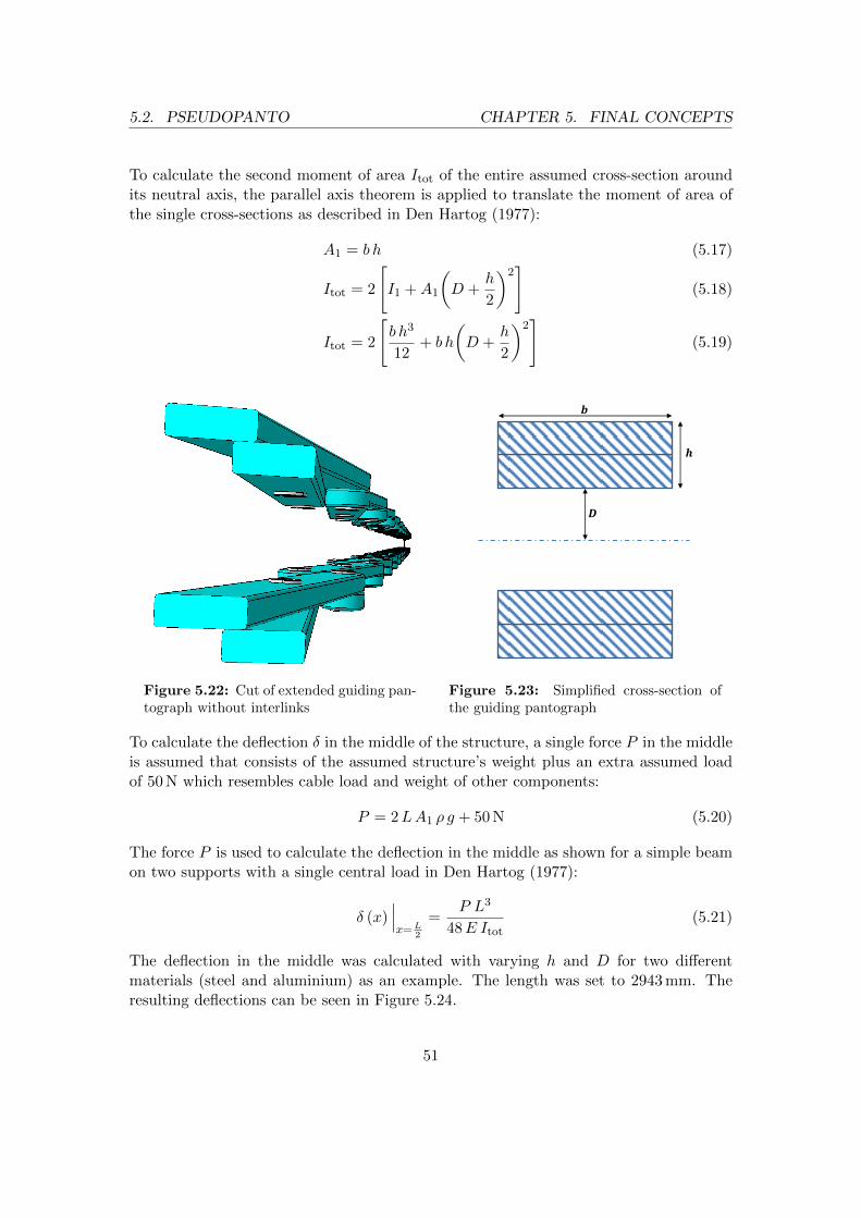
5.2. PSEUDOPANTO CHAPTER 5. FINAL CONCEPTS
To calculate the second moment of area Itot of the entire assumed cross-section aroundits neutral axis, the parallel axis theorem is applied to translate the moment of area ofthe single cross-sections as described in Den Hartog (1977):
A1 = b h (5.17)
Itot = 2
[I1 +A1
(D +
h
2
)2]
(5.18)
Itot = 2
[b h3
12+ b h
(D +
h
2
)2]
(5.19)
Figure 5.22: Cut of extended guiding pan-tograph without interlinks
𝑫
𝒉
𝒃
Figure 5.23: Simplified cross-section ofthe guiding pantograph
To calculate the deflection δ in the middle of the structure, a single force P in the middleis assumed that consists of the assumed structure’s weight plus an extra assumed loadof 50 N which resembles cable load and weight of other components:
P = 2LA1 ρ g + 50 N (5.20)
The force P is used to calculate the deflection in the middle as shown for a simple beamon two supports with a single central load in Den Hartog (1977):
δ (x)∣∣∣x=L
2
=P L3
48E Itot(5.21)
The deflection in the middle was calculated with varying h and D for two differentmaterials (steel and aluminium) as an example. The length was set to 2943 mm. Theresulting deflections can be seen in Figure 5.24.
51

5.2. PSEUDOPANTO CHAPTER 5. FINAL CONCEPTS
Table 5.3: Variables used for the bending analysis
Variable Description
b Width of a pantograph arm
h Height of two pantograph arms
A1 Cross-section of two pantograph arms
2D Distance between two facing pantograph arms
I1 Second moment of area of the cross-section A1
Itot Second moment of area of the total cross-section
L Length of structure
ρ Density of material
g Acceleration of gravity
P Force of bending in the middle
δ (x) Deflection at position x from structure’s end
E Young’s modulus
68
1012
1416
5
10
15
0
2
4
6
8
10
D
Steel
h
Deflection in m
m
2
3
4
5
6
7
8
9
10
(a) For steel
68
1012
1416
5
10
15
0
2
4
6
8
10
D
h
Aluminium
Deflection in m
m
4
6
8
10
12
14
16
18
20
(b) For aluminium
Figure 5.24: Deflection in dependence of D and h of the guiding pantograph
Pantograph Arms
The arms of the pantograph were chosen to be as thin as possible to avoid growing ofthe structure in the X-direction of the truck and thus interference with the trailer sweep.The cross-section and the geometry were kept rectangular and thus simple to be able tokeep production low-cost. The width of the arms was kept as small as possible to achievea minimal total height of the pantograph when folded. The arm length was set to be able
52

5.2. PSEUDOPANTO CHAPTER 5. FINAL CONCEPTS
Figure 5.25: Cut of guiding pantograph: 1 bushings, 2 & 3 distancers, 4 bolts, 5 nuts
to provide the total necessary prolongation length without unfolding the pantograph toits maximum extension length. The maximum extension length was avoided since itwas considered instable and a probable hinder for folding if friction was considered andbecause overshooting of the cab after reaching the tilted position had to be assumed. Thelength of the arms was also restricted by components near the placing of the pantographwhich should not be touched during the entire tilting operation. To decide on the totalnumber of arms, considerations concerning the cable channels (see section 5.2.4) wereintegrated.
Pantograph Joints
The pantograph arms are linked by simple screws or bolts with lock nuts and distancesleeves. The bolts where chosen to be of gauge 5 mm in diameter. The two pantographsare held on distance by the distance sleeves on the bolt. The lock nuts provide a certainforce for compression between the arms and the two pantographs so they sit tightly. Thecompression must not be too high in order to make sliding between the arms possiblewithout any significant resistance.
To allow good gliding of the joints, the bolts are running inside polyamide bushingswhich are placed inside holes in the pantograph arms. The polyamide bushings thusserve as bearings. In a joint between two arms, one bushing is placed so the faces of twopantograph arms can touch each other to improve bending behaviour in the extendedposition (explanation is given in section 5.2.7). The flange of the bushings serves as asupport for the lock nuts on the outside of the pantograph in the back and as a supportfor the distance sleeves between the pantographs and between the front pantograph andthe cable channel. The assembly of the guiding pantograph can be seen in Figure 5.25.
53

5.2. PSEUDOPANTO CHAPTER 5. FINAL CONCEPTS
5.2.4 Cable Channel Pantograph
To guide the cabling on the guiding pantograph, cable channels (see Figure 5.26) areused. The cable channels are mounted on the pantograph in the geometrical centre ofgravity of their back wall. The channels are connected by special hinges which link themovements of the channels together. The cable channels fold and unfold in a zigzag in apseudo-pantographic manner, i.e. their movement is kinematically linked to the actualpantograph. Thus the cable channels fold just like a pantograph but geometrically theyare not a pantograph.
Figure 5.26: Normal size cable channel with retracted drawer
The kinematics of the linked cable channels build on the observation that a pantographwhich is an integer multiple in size of a second pantograph geometrically shares certaincommon intersections of the scissors with the second pantograph, i.e. if the first panto-graph is n times larger than the second, the second pantograph shares each n-th scissorcrossing with the larger pantograph. These common intersections find themselves alwaysin the same positions towards each other, independent of the current pantographic angleand thus extension. This principle can be seen in Figure 5.27.
𝐿
2
2𝐿
2
3𝐿
2
Figure 5.27: Relationship between pantographs of integer multiple size
54

5.2. PSEUDOPANTO CHAPTER 5. FINAL CONCEPTS
In the PseudoPanto this fact is used by designing the cable channels a factor of 2 longerthan the arms of the guiding pantograph. The cable channels are thus connected intheir middles to each second scissor on the behind pantograph (see Figure 5.28). As theguiding pantograph ends in single joints, i.e. the ends of the pantograph are comprisedof half-length arms, smaller cable channels are connected to the end joints. Togetherwith the design of the hinges that connect all channels and just leave rotation aroundthe hinges’ axis free, the zigzag structure of the cable channels becomes kinematicallylinked towards the guiding pantograph if weight is ignored. The movement of the guidingpantograph thus determines the movement of the cable channel, which is desirable tobe able to predict the motion. The cable channels consist of three main parts which aredescribed in the following sections.
Figure 5.28: Cable channel pantograph on the guiding pantograph
Cable Channel
There are two types of cable channels, the normal ones and the shorter ones for the ends.Their design is almost the same and can be exemplified by looking at the normal onesfirst and then pointing out the differences of the smaller ones.
The cable channels are fixed rotationally free towards the guiding pantograph. It has ahole in the geometrical centre of the its plane facing the pantograph in which anotherpolyamide bushing is inserted like in the joints of the pantograph arms. In the smallchannels this hole is located close to the end of the channel (Figure 5.29). The hole and
55

5.2. PSEUDOPANTO CHAPTER 5. FINAL CONCEPTS
the bushing are aligned with the crossing joint of the scissor behind it and are connectedby one and the same bolt and lock nut. To keep a certain distance between the back wallof the main channel and the pantograph arms and to keep contact pressure, a distancesleeve is used.
Figure 5.29: Small cable channel
At their ends, the large channels have two disparate hinges. The hinges are locatedin the upper or lower diagonal corners of the channel. Since a large channel is alwayslinked to a channel above and below itself, there are two variants of the placing of thehinges, i.e. either top-right with bottom-left or top-left with bottom-right (see Figure5.30a and 5.30b). The small cable channels only have one hinge which is connected to alarge channel. The hinges are designed so that in the folded position the cable channelsall lie parallel to each other with 5 mm space between them (see Figure 5.31). The frontof the channels has a cut-out to insert the drawers that are described later.
(a) Form A (b) Form B
Figure 5.30: Normal size cable channels
To choose an adequate length of the cable channels and the pantograph arms accord-ingly, a desired total length of all channels was set to 2900 mm. The folded cable channelpantograph could be seen as a structure of rows which are comprised of a cable channel’sheight and the vertical distance to the next channel (see Figure 5.31). In the chosen de-sign this row height is 40 mm. The structure is one cable channel wide in folded position.It has to be considered that the two small channels together stand for one channel when
56

5.2. PSEUDOPANTO CHAPTER 5. FINAL CONCEPTS
Figure 5.31: Folded cable channel pantograph with parallel channels
looking at the length, but they must be seen as two channel rows when looking at theheight since they are not located in the same plane.
The maximum space available on the back wall of the cab in Z-direction of the truckwas measured to be 405 mm. The maximum number of channel rows thus becomes:
405 mm
40 mm= 10,1
This means that 10 channel rows can be used at maximum. This means that 9 chan-nel lengths is the maximum, which leads to 10 channel rows as explained above. Theresulting arm length would be:
2900 mm
9= 322,2 mm
The maximum space available in the width (Y-direction of the truck) is restricted by acomponent behind the cab back wall called trailer arch. With leaving some extra spaceof 11 mm to the trailer arch, the channel length may be 430 mm at maximum. Thenumber of necessary channels thus becomes:
2900 mm
430 mm= 6,7
7 channels lengths must thus be used under these conditions, which leads to 8 channelrows in height. To keep away from these extremes the design was set to 8 channel lengthswhich means 9 channel rows in height. In this case not too much space in the Y-directionis used which means a safe distance from components like the trailer arch. Also, the totalheight is not too large which means fewer possibilities to clash with components on theback of the cab. With 8 channel lengths the arm length must be at least:
2900 mm
8= 363 mm
The arm length was chosen to be 370 mm to be able to compensate for not totallystretched arms in the final position.
57

5.2. PSEUDOPANTO CHAPTER 5. FINAL CONCEPTS
Drawer
The drawer is an insert that is put inside the predefined slot in the cable channel. Itcan be taken out for mounting wires inside the cable channel. The insert incorporatesslots in its bottom which allow fixing of the routed wires with cable ties to the bottom.Furthermore, slots along the insert’s contacting surface provide a possibility for bettersealing. There are two different drawers, one for the big and one for the small cablechannels. Their design is alike and can be seen in Figure 5.32.
(a) Normal size (b) Locking mechanism on drawers
Figure 5.32: Cable channel drawer
To prevent unwanted opening of the drawers under driving they are equipped with asimple locking mechanism on both of their ends. A pin with a slot for a screwdrivercan be operated from the outside to rotate the attached locking pin to a closed or openposition (see Figure 5.32).
Edge Protection
The transitions from one cable channel to the other are the exposed parts of a cableroute on the product. Since these edges bend a lot during the pantographic motionthey have to be protected by a flexible layer that keeps away water and dirt. The exactmaterial for this purpose was not chosen during this project. Ideally it is a fabric thatis impenetrable by water and other liquids and endures rough environments. It shouldalso be able to be glued to rigid bodies.
To tightly fit such a fabric over the edge of the cable channels, a simple clamping mecha-nism (see Figure 5.33) was developed. The tightening bars of the clamp form a rectanglewhich fits in prepared grooves on the cable channel. The chosen fabric should be gluedwith sealing glue inside these grooves. Then the clamp is put in the grooves as well withthe fabric between the clamp and the channel. The clamp has a simple lever like on oldjam jars which is pushed down into a locked position and thereby pulls a metal shacklewhich clamps the whole structure together.
58

5.2. PSEUDOPANTO CHAPTER 5. FINAL CONCEPTS
Figure 5.33: Opened clamping mechanism on the cable channel
5.2.5 Bottom Support
For the positioning on the bottom it was chosen to take the right cab lock as a connec-tion point. The right side offered the most space on the target truck and furthermorethe air intake posed an obstruction on the left side. The cab lock was chosen as thepreferred positioning because it does not execute any relative motion towards the cabin the locked position under driving. This leads to less movement of the whole productand thus the cabling under driving. Relative movement only arises below the cab lockwhere the suspension system is located.
The guiding pantograph is fixed with a rotational joint to a bracket which acts as asupport for the pantograph on the chassis. The bracket consists of an arm and an anglewhich has two holes. The angle is adapted to the geometry of the cab lock and thetwo holes are the interface for the two cab lock bolts. The bolts can be removed andreinserted in the cab lock with the bracket between them. The bracket is designed forstiffness to be able to always hold the PseudoPanto in the same bottom position.
The end of the bracket’s arm is connected to a fork which is linked to the bottom tip ofthe guiding pantograph. This fork is rotationally free around the Y-axis in a 90◦ sectortowards the back of the cab (see Figure 5.34).
The bottom support positions the bottom point of the guiding pantograph. The posi-tioning of the bottom point is almost in the middle of the cab lock in Y-direction, acertain length away from the back wall of the cab in the X-direction and approximatelyin flush with the top of the cab lock in Z-direction to avoid clashes under the tiltingprocess.
59

5.2. PSEUDOPANTO CHAPTER 5. FINAL CONCEPTS
Figure 5.34: Bottom support Figure 5.35: Mounted bottom support
5.2.6 Top Support
To connect the top of the pantograph to the cab, the problem of the pantograph’s heightin folded position had to be overcome. When folded and fixed to the bottom connection,the pantograph’s top still resides above the cab’s back corner in substantial distance.Since unfolding and remaining with this overlap would result in a clash between thecab’s back edge and the pantograph before reaching the tilted position, a solution formoving the pantograph’s top towards the cab’s back edge under tilting had to be found.
Figure 5.36: Swallowtail interface withoutpantograph
Figure 5.37: Swallowtail interface withpantograph
60

5.2. PSEUDOPANTO CHAPTER 5. FINAL CONCEPTS
This difficulty was overcome by a simple sliding rail with a swallowtail interface (seeFigure 5.36); by using a vertical rail mounted on the back of the cab (see Figure 5.37),the connection point of the pantograph automatically moves to the cab’s back edgeunder inclination. When reclining the cab, the connection point moves upwards on therail until the locked position is reached again. The rail can be mounted on the back ofthe cab with screws and a bracket on its bottom that also fixes it towards the right maincab beam.
5.2.7 Prototype Testing
Before development could proceed to DL2, a full, real-size prototype from DL1 (partsvisible in Figure 5.38) had been created and tested. Certain design decisions were takenafter the testing which highlighted design flaws. In this section the insights from proto-typing and testing are described and the design changes explained and justified.
(a) Guiding Pantograph (b) Cable Channels mounted
Figure 5.38: PseudoPanto Prototype
Prototypes Insights
By testing the movement of a single pantograph it could be seen that if the pantographarms consisted of planar scissors, i.e. two arms of a scissor touched each other on theirfacing planes during the movement, their bending deflection was improved. In a previousdesign the flanges of the polyamide bushings were meant to keep a distance between twofacing pantograph arms. Removing this feature showed clearly less deflection under self-weight in the maximum extended and the maximum folded position. It is assumed thatsubstantial shortening of the effective bending length for the cross section of a single armin these positions is the reason for this behaviour (see Figure 5.39); if the faces of thearms can touch each other, they can also support each other. The greater the area of theone arm that is projected on the other, the higher the overall stiffness of the consideredsection. This will be called the area support effect in this report.
61

5.2. PSEUDOPANTO CHAPTER 5. FINAL CONCEPTS
(a) Low effect (b) High effect
Figure 5.39: Area support effect
Testing a single pantograph also showed that bending under self-weight in the extendedstate was so substantial that trying to push it back into the folded position only resultedin even more bending due to friction. On a reclining cab this would have inevitably ledto plastic deformation and destruction.
Furthermore, the pantograph was seen to unfold first on its top when mounted on thetruck. The lower scissors of the structure followed later. This behaviour can be ex-plained by the elasticity in the structure, the non-perfect fit of the bolts in the holes ofthe pantograph arms and weight force pushing on the lower scissors. In some cases thiseven led to a negative pantographic angle of the bottom arms which could have damagedthe structure if the extension was not reversed and the error fixed.
Mounting the prototype on the truck appeared to be easy. The stiffness of the bottomsupport was seen to not be sufficient though as substantial bending occurred alreadyin the static locked position when mounted. It was concluded that the design of thebending cross-section of the bottom support was inadequate.
Adding Stiffness
The lack of stiffness in the prototype led to the conclusion to choose a double pantographas the guiding mechanical structure. This increases stiffness of the structure but leads tolarger outer dimensions of the product. Furthermore, the discovered area support effectwas used in the current design by designing the pantograph arms to be parts of planarscissors.
Hinges
The new hinges build on the paradigm of linking the guiding pantograph kinematicallyto the cable channels as explained in section 5.2.4. The previous hinges allowed one moreaxis of rotation to be free, in parallel to the current. These hinges restricted the hingingangle between certain values though. This concept did not work as folding of the cablechannels exposed a chaotic movement which was hard to predict.
62

5.2. PSEUDOPANTO CHAPTER 5. FINAL CONCEPTS
Top Support
Two concepts were tested to act as a top support; the swallowtail rail as described insection 5.2.6 and an extender mechanism (see Figure 5.40). The extender should extendfrom a folded position by rotating around a fixed point on the cab under inclination.This rotation should lower the top point of the pantograph and prevent clash with thecab. This concept proved not to work as a folded position could not be sustained in thelocked position. The swallowtail rail however proved to work perfectly under testing.
Figure 5.40: Discarded extender mechanism
5.2.8 Material Considerations
A simple analysis on material choice for most of the parts of the PseudoPanto was con-ducted with the help of the CES software. The material selection process followed Ashby(2011). The used variable can be seen in Table 5.6. Certain base requirements were seton all parts; low flammability and high durability in humid and wet environments.
Pantograph Arms
The arms of the double pantograph can be seen as beams loaded in bending with stiffness,length, width specified and height as a free parameter. This is a standard problem inAshby (2011) and including costs this leads to the material index
M1 =E
13
Cmρ(5.22)
Table 5.4 shows the results of the material selection in CES (see Appendix C.6).
Table 5.4: Material selection of the pantograph arms
Material ρ σf Cm
Stainless steel austenitic,AISI205 wrought, annealed
7850 kgm3 425 MPa 11 - 12 SEK
kg
63

5.2. PSEUDOPANTO CHAPTER 5. FINAL CONCEPTS
Bottom Support and Top Support
The material requirements for these components were seen to be alike; high stiffness andyield strength. As a secondary factor, cost was tried to be kept low. An analysis in theCES software led to the same material choice as for the pantograph arms above.
Cable Channels
The cable channel was seen to be an exposed structure that may had to tolerate suddenhits by other bodies, which requires low brittleness (high K1c). Furthermore, it shouldnot fail under static load (high σf ). The analysis in CES (see Appendix C.6) yielded thefollowing material recommendation in Table 5.5.
Table 5.5: Material selection of the cable channels
Material ρ σf Cm K1c
Magnesium, commercialpurity
1740 kgm3 65-100 MPa 21-23 SEK
kg 50-70 MPa m12
Polyester SMC (25% glassfiber, self-extinguishing)
1750 kgm3 55-83 MPa 22-29 SEK
kg 15-37 MPa m12
Table 5.6: Variables used in the material selection
Variable Description
E Young’s modulus
Cm Price per kg in SEK
ρ Density
σf Failure strength (yield, fracture)
K1c Fracture toughness
5.2.9 Summary & Further Development
A summary can be drawn in Table 5.7 which assumes PseudoPanto to be realised in therecommended materials. The summarised data is taken from the bill of materials seeAppendix C.5).
Since the PseudoPanto has been created from scratch, it still needs further developmentwith the input of specialists at Volvo to reach an adequate state of maturity. Certaindetails still need to be decided and further testing with prototypes in the target materialis advised.
64

5.2. PSEUDOPANTO CHAPTER 5. FINAL CONCEPTS
Table 5.7: Summary of PseudoPanto
Total number of parts 547
Number of different parts 36
Total material cost 328 SEK
Total weight 25 kg
The bracket of the bottom support needs better geometrical fitting to the cab lock andmay need a redesign to ensure minimal deflection with minimal material input.
The material and type of the edge protection needs to be chosen to fulfil the require-ments of protection in these areas. The design of the cable channels in their edges mayalso need a redesign to facilitate mounting of a cable route. The current design demandsthat one end of the cable route is put through all the openings of the cable channels. Anoptimal solution would allow that the cable route can just be put into all cable channelsat the same time. This could be reached by designing clip closers on the edges that canbe closed easily after putting the route in all cable channels.
It should furhtermore be made possible to route the wires in the edges in a manner thatmostly moves and loads the wires rotationally around their long axis. This load case isto prefer to pure bending for copper wires which might lead to fatigue due to the cyclicloading.
To facilitate maintenance and replacement of parts on the tilted truck, the bottom con-nection point of the guiding pantograph should be made detachable. Thus the wholestructure of the PseudoPanto could be moved out of the way in order to reach certaincomponents underneath it.
Further development should also strive to minimise the number of fixing elements (screwsand bolts) in the concept and maybe reach a more integrated design. The current numberof parts seems unproportionally high for this concept.
65

5.3. SELFIE CHAPTER 5. FINAL CONCEPTS
5.3 Selfie
This section describes the final development stage of the chosen concept under the plugapproach, called Selfie. In the following sections the general idea of the concept willbe described. Detailed designs cannot be presented in this report since Volvo decidedto proceed with the concept and aims for patenting certain parts of the mechanism.Publishing details about the solution in this report would make a patent impossible.Therefore pictures of the final version of this concept cannot be shown. However, certaininsights from the prototyping and testing will be described and material considerationswill be discussed.
5.3.1 General Idea
The main goal in the plug approach was to satisfy the main function Allow Tilting by acoupleable solution for the electric contacts. Furthermore, the focus was set on achievinga fully automatic unplugging of the contact under inclination and a fully automatic plug-ging under declination of the cab. Selfie is a concept that satisfies all these requirements.It works fully mechanical and is independent of external energy sources as it uses thepotential energy of the cab’s weight to operate its own coupling and locking mechanism.The solution does not need human interaction under the entire operation. This is madepossible by a fully reversible movement of the mechanism in Selfie.
In the next sections first the theoretical issues around plugging concepts on a truck arediscussed, followed by a description of how certain challenges were overcome on a generallevel.
5.3.2 Plugging Challenges
During development certain obstacles had to be overcome which are generally inherentin plugging mechanisms. Separating electrical circuits in a contact implies the exposureof electrical contact surfaces. This leads to issues with corrosion, wear and signal quality.Furthermore, a plug poses additional requirements on contacting force, contact protec-tion in an open state, sealing against the outside conditions, locking and holding theplugged contact in position and ensuring a correct guiding of the plug before it reachesthe contacting point. A short description of these challenges is given in the following.
Connector Design
The main function of electronic connectors is to transmit power or signals between twounits. The transmission should comprise only acceptable losses in power or signal qual-ity. In order to reach this, a connector should have as little impact as possible on theelectrical properties of the circuit, i.e. its contact resistance should be low and invariant.(Mroczkowski, 1992)
66

5.3. SELFIE CHAPTER 5. FINAL CONCEPTS
Figure 5.41: Example of a coupled connector with the contact spring visible (in Wiki-media Commons, the free media repository, Retrieved 2014-07-15 from: http://commons
.wikimedia.org/wiki/File:Jack-plug--socket-switch.jpg)
Standard connectors commonly consist of a housing called plug on the one side whichcontains the male pins and a housing called receptacle which contains female socketson the other side of the connection (Christ & Wernli, 2014). To achieve the signal orpower transmission the connector must provide and sustain a metal-to-metal interfacebetween the contact points which is mostly achieved by a contact spring (example pro-vided in Figure 5.41 which provides the necessary force for the interface (Mroczkowski,1992). The contact spring is often comprised by the electrical contact itself. In general,the higher this contacting force on the individual pins the higher also the needed mat-ing/unmating force of a separable connector.
The pins and sockets of a connector usually consist of a base material (in most casescopper) which is coated by a protective metal layer that prevents exposure of the basemetal to the environment. There are many coating variants, the most used in theautomotive industry are gold, silver, nickel and tin. (Volvo, 2014)
Corrosion and Wear
Connectors on a heavy duty truck are particularly sensitive to corrosion by fretting.Fretting arises from small amplitude movements up to 100µm between the contactingsurfaces of electronic connectors. These movements can be induced by external mechan-ical and electromagnetic vibrations or temperature changes. Fretting alone leads to wearand metal transfer between the contact partners. In case base metal contacts are usedthis leads to oxidation of the surface or the wear debris that has been built up during themovements. This situation is then called fretting corrosion. The debris may accumu-late in the contact zone and leads to increased contact resistance. (Antler, 1985b, 1985a)
67

5.3. SELFIE CHAPTER 5. FINAL CONCEPTS
Especially separable connectors that are mated at relatively low forces are prone to fret-ting (Antler, 1985a). Flowers, Xie, Bozack, and Malucci (2004) have shown that frettingcorrosion seems to have a threshold behaviour, i.e. degradation of the contact materialsby fretting seems to be insignificant at different frequencies below a certain excitationlevel. In the case of a heavy duty truck, the necessary vibrations for fretting corrosionare omnipresent during truck operation due to excitations by the engine and the suspen-sion system during driving (Volvo, 2014). To minimise the extent of fretting, vibrationbetween the contacting members should be impeded and high contacting force shouldbe provided (Volvo, 2014).
Wear on separable connectors is mainly induced by friction during inserting and with-drawing the pins in the connection. The amount of friction is linked to the contactingforce provided by the contact springs. The friction when sliding the contact has the pos-itive effect of removing surface particles, for instance oxides from the debris of fretting,and thus achieve good electrical contact (Moran, Sweetland, & Suh, 2004; Volvo, 2014).On the other hand wear sets a limit to the number of plugging/unplugging cycles as itdegrades the coating metal gradually which leads to exposure of the base material.
Guidance
One big challenge that has to be overcome in the design of a fully automated contactat the back of a truck is to ensure correct guiding of the plug into the receptacle underreclination. Since no human interaction should be needed in this coupling process, aguidance has to achieve first a catching of the opposing contact onto the guidance systemitself and a subsequent controlled movement of the contacts towards each other until themated state is reached. The mechanism of catching the opposing contact has to be ableto compensate for position misalignments between the cab and the chassis during thelanding phase. The controlled movement of the contacts towards each other has to beable to cope with the almost vertical but in practice unpredictable landing motion of thecab on the chassis (see section 3.2). Vice versa the guidance should ensure a controlledunmating of the contacts during inclination.
Locking, Sealing and Protection
The coupled connection needs to be locked in position when the mated state has beenreached. This inhibits unintended opening of the connection and adds to the wantedrigidity of the bond. Conversely, unlocking has to occur automatically during the incli-nation operation before the connection can hinder the movement of the cab.
In the locked state, an automatic connection should furthermore provide sealing againstthe harsh environment on a truck. Under driving, the sides and the back of a truck canbe enfolded by fine spray of water, oil and other aerosols which are able to reach evensmall gaps and cracks (Volvo, 2014).
68

5.3. SELFIE CHAPTER 5. FINAL CONCEPTS
In both an open and closed state a connector needs protection from external forcesand impacts. The protection should furthermore be insulating for electric current andelectromagnetic fields to ensure low signal perturbation and thus noise.
5.3.3 Selfie Parts
Selfie consists generally of one chassis-mounted (lower) and one cab-mounted (upper)part. The lower part embodies the plug which possesses certain degrees of freedom. Theupper part embodies the receptacle which is rigidly fixed and enwraps the plug in thelocked state. A description of these two parts is given in the following sections.
Chassis-Mounted
The lower part of Selfie is mounted on its bottom to the chassis by a bracket that consistsof an arm and an angle. The bracket is fixed to the cab lock with the locking screwsin the same manner as the PseudoPanto’s bracket which was described in section 5.2.5.Also here, the cab lock serves as a connection point which does not move relative to thecab under driving. This fact eases the requirements posed on Selfie.
The arm of the bracket holds a system of sliders and rotational joints which give thestructure built upon them the needed degrees of freedom in the required magnitude.This results in a limited free movement in the X- and Y-direction and rotation aroundthe Y- and Z-axis of the truck to cope with position variations between cab and chassis.
On top of the lower part, upon the system that permits the movement, the plug andthe locking system are mounted. The plug is a symmetric structure that contains acommercial electrical connector in its centre. The plug possesses a specific geometry onits outside which supports the mating operation. Wires are routed from the commercialconnector on the inside through the bottom of the plug from where they can be har-nessed by a standard corrugated hose on the chassis.
The locking system is located slightly below the plug to which it is rigidly fixed. Lockingand unlocking is performed by physical insertion and retraction of specific parts of thelock into the corresponding part. The locking process is designed to begin when thereclining cab has entered the landing phase during reclination and thus majorly movesvertically towards the ground. Conversely, unlocking of the mechanism is completedslightly before the end of the take-off phase during inclination.
Cab-Mounted
The upper part of Selfie is mounted at the back wall of the cab centred above the cablock in the locked position of the cab. The part consists mainly of a shell-like componentcalled Outer Shell that can be opened on its top for mounting wires. The Outer Shellcomprises an opening on its bottom which is directed towards the lower part in the locked
69

5.3. SELFIE CHAPTER 5. FINAL CONCEPTS
position of the cab. The opening is designed to correspond to the specific geometry ofthe plug and the allowed position variation between cab and chassis. Above the bottomopening the Outer Shell features a short tunnel in which the plug is meant to glide uptowards the mated position. The Outer Shell thus provides the required guidance andprotection for the plug by its structure.
At the end of the tunnel in the Outer Shell a component called Antiplug is mounted.The Antiplug resembles a negative of the plug in its geometry which facilitates a perfectmating between their outer surfaces and thus provides sealing. The Antiplug containsthe opposing electrical connector in its centre. Wires are routed from this connectorthrough the top (removable) part of the Outer Shell from where they are harnessed bya standard corrugated hose on the cab.
Electrical Connectors
The commercial connectors used in Selfie are a Deutsch DRC12-40PA in the plug cou-pled to a Deutsch DRC16-40SE in the Antiplug, with capacities for 40 pins and sockets(drawing see Appendix C.4). The fully equipped connectors alone can be seen in Figure5.42. The adequate pins and sockets are nickel coated and are suited for a wire gaugeof up to 2,5 mm2. The connector normally includes a screw which ensures a tight fit ofthe connection. The screw has been removed for the application in Selfie where othercomponents take over the same function.
Figure 5.42: Deutsch DRC connectors in Selfie
The connectors are well-suited for harsh environments since they are mostly used inmilitary applications. The connectors are designed to endure frequent coupling. Thedesign of the pins with a chamfer allows a certain misalignment towards the sockets.Crimping of the pins and sockets towards the copper wires is relatively easy and fast.The nickel coating provides a relatively hard surface which is beneficial for the wearresistance.
70
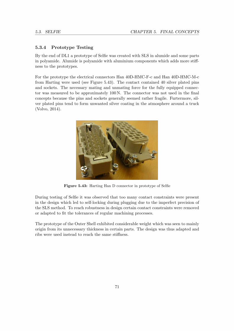
5.3. SELFIE CHAPTER 5. FINAL CONCEPTS
5.3.4 Prototype Testing
By the end of DL1 a prototype of Selfie was created with SLS in alumide and some partsin polyamide. Alumide is polyamide with aluminium components which adds more stiff-ness to the prototypes.
For the prototype the electrical connectors Han 40D-HMC-F-c and Han 40D-HMC-M-cfrom Harting were used (see Figure 5.43). The contact contained 40 silver plated pinsand sockets. The necessary mating and unmating force for the fully equipped connec-tor was measured to be approximately 100 N. The connector was not used in the finalconcepts because the pins and sockets generally seemed rather fragile. Furtermore, sil-ver plated pins tend to form unwanted silver coating in the atmosphere around a truck(Volvo, 2014).
Figure 5.43: Harting Han D connector in prototype of Selfie
During testing of Selfie it was observed that too many contact constraints were presentin the design which led to self-locking during plugging due to the imperfect precision ofthe SLS method. To reach robustness in design certain contact constraints were removedor adapted to fit the tolerances of regular machining processes.
The prototype of the Outer Shell exhibited considerable weight which was seen to mainlyorigin from its unnecessary thickness in certain parts. The design was thus adapted andribs were used instead to reach the same stiffness.
71

5.3. SELFIE CHAPTER 5. FINAL CONCEPTS
5.3.5 Material Considerations
A simple analysis on material choice for some of the parts of Selfie was conducted with thehelp of the CES selector. The material selection process followed Ashby (2011). The usedvariables are the same as in section 5.2.8 (see Table 5.6). Certain base requirements wereset on all parts; low flammability and high durability in humid and wet environments.
Outer Shell
The Outer Shell can be seen partly as a panel structure with stiffness, length and widthspecified and thickness as a free parameter. This is a standard problem in Ashby (2011)and yields the material index
M1 =σ2fρ
(5.23)
Furthermore, K1c was required to be high to achieve resistance against sudden impactsby material from the environment. The analysis in CES (see Appendix C.6) yielded thematerial recommendation in Table 5.8.
Table 5.8: Material selection of the Outer Shell
Material ρ σf Cm K1c
Stainless steel, martensitic,AISI403 wrought, annealed
7700 kgm3 245-550 MPa 7,1-7,9 SEK
kg 37-156 MPa m12
Plug and Antiplug
The requirements set on these parts were a minimum level of stiffness and good insulationproperties since they comprised the electric connectors. The search in the materialdatabase then aimed for low price and high strength. Furthermore, good insulationproperties for low noise induction and good gliding properties of the material againstthe material of the Outer Shell were considered. The selection yielded thermosets orthermoplastics as a material recommendation (see Appendix C.6 for chart). Table 5.9shows one viable example of each group.
Table 5.9: Material selection of the Plug and Antiplug
Material ρ σf Cm
Thermosets: Phenol fromaldehyde (PF)(cotton filled, impact modified, molding)
1400 kgm3 33 - 55 MPa 15 - 16 SEK
kg
Thermoplastics: Polyphenylene oxide /polystyrene alloy (30% glass fiber)
1300 kgm3 95 - 105 MPa 23 - 34 SEK
kg
72

5.3. SELFIE CHAPTER 5. FINAL CONCEPTS
5.3.6 Summary & Further Development
A summary can be drawn in Table 5.10 which assumes Selfie to be realised in therecommended materials.
Table 5.10: Summary of Selfie
Total number of parts 117
Number of different parts 35
Total material cost 193 SEK
Total weight 20 kg
Like the PseudoPanto, Selfie was created from scratch. Selfie needs further developmentand especially testing to become a mature concept. The mechanism itself seems to work,downscaling might though be possible with more knowledge about locking mechanisms.
Testing of a prototype in the target material is advised to observe the actual behaviourand gliding properties of the locking mechanism and the plug inside the Outer Shell.Different material pairings and tolerances might be examined and tested to reach opti-mal gliding behaviour and to make self-locking impossible.
Some parts of Selfie are not or not fully developed but needed before the concept can beimplemented:
• A protection mechanism for the electric connector of the plug in the open state hasnot been designed but would be needed to prevent exposure to the environment
• An extension cable should be designed and provided for maintenance staff to beable to close the circuit in the tilted position for tests
• The design of the bottom system that provides the lower part of Selfie with itsdegrees of freedom is rather simplistic and should be improved to reach a smoothand robust movement
• Generally, steps to reach an integrated design of the parts should be taken tominimise the number of different parts
73


6Conclusions
The goal of the thesis has been fulfilled as two new alternative harness routing con-cepts have been developed. The concept created following an approach to prolong theconnection is called PseudoPanto. It has been tested and the working principle hasbeen confirmed. The other concept created followed an automatic coupling approachand is called Selfie. A fully working prototype for Selfie could not be tested under thedevelopment time. The developed concepts show that alternative routing solutions aretechnically possible, however the question remains how much of the cabling can be re-routed. PseudoPanto is more mature in its development than Selfie, yet the adaptabilityof PseudoPanto for more cabling is seen more problematic than in Selfie. One should beclear about the objectives during a selection of one of the presented concepts.
Considering aftermarket circuit diagnosis for error searching, both concepts exhibit ad-vantages and disadvantages; Selfie needs an extra extension cable in the tilted statebecause the circuit of the cabling must be closed for error search purposes. As errorsearch is not needed under every tilting operation, the extent of this disadvantage de-pends on the frequency of error search actions on the truck which is unknown at thisstate. PseudoPanto on the other hand does not pose any problem for circuit diagnosisas its circuit is always closed. It might though cause a problem by inducing a physicalobstruction if large components close to PseudoPanto have to be replaced. In thosecases the PseudoPanto might be in the way of special tools and machines which need toreach those components. Therefore the PseudoPanto needs to be detachable at certainpoints to be able to move it out of the way. The extent of this disadvantage dependson the frequency replacing such components which is also unknown. To draw soundconclusions, both the frequency of the error searching and component replacement haveto be assessed. A way to circumvent both problems in future concepts could also be acombination of the two approaches, i.e. a prolongable solutions which can furthermorebe coupled.
75

CHAPTER 6. CONCLUSIONS
It was observed that direct contact with employees at Volvo led to good results in gath-ering information. Indirect contact (e.g. mail) did not lead to the same quality ofinformation. The use of a mediating object (truck model) was a great way to commu-nicate a subject which was hard to describe. The truck model helped to manifest anabstract idea of the authors on a physical artifact which was familiar to the interviewees.It seemed as the recognition of a well-known object led also to a higher willingness ofthe interviewees to respond and describe their thoughts.
A considerable amount of time was put into the pre-study to set the scope of the thesisproject which stole time from a more extensive detail development of the concepts inthe end. In retrospect it can be said that the time used in the pre-study should havebeen compressed as much as possible to start a focused development earlier in the process.
The situation of working in the borderland between two different CAD systems (ProE onchassis and Catia V5 on cab) was seen as a time consuming obstruction. Time had to bespent on finding and converting CAD data in question to be able to work. Furthermore,working in an area of the truck which involves a lot of different area responsible groupsincreased the time needed for information gathering. Most area responsible groups wereusually fully aware of their own situation but unaware of others.
Regarding the process of concept screening it should be noted that the authors heldlimited knowledge about how the created concepts would perform in real life due to ageneral nescience about trucks. Therefore, many assumptions had to be made during theconcept evaluations. The gathered knowledge from Volvo employees helped to overcomethis obstacle partly.
76

Bibliography
Antler, M. (1985a). Electrical effects of fretting connector contact materials: A re-view. Wear , 106 (1–3), 5 - 33. Retrieved from http://www.sciencedirect.com/
science/article/pii/0043164885901012 doi: http://dx.doi.org/10.1016/0043-1648(85)90101-2
Antler, M. (1985b, Mar). Survey of contact fretting in electrical connectors. Components,Hybrids, and Manufacturing Technology, IEEE Transactions on, 8 (1), 87-104. doi:10.1109/TCHMT.1985.1136462
Ashby, M. F. (2011). Materials selection in mechanical design (4th ed.). Burlington,MA: Butterworth-Heinemann.
Bryman, A., & Bell, E. (2003). Business research methods. Oxford UniversityPress. Retrieved from http://common.books24x7.com.proxy.lib.chalmers.se/
toc.aspx?bookid=12878
Christ, R. D., & Wernli, R. L., Sr. (2014). Chapter 8 - cables and connec-tors. In R. D. Christ & R. L. Wernli (Eds.), The {ROV} manual (sec-ond edition) (Second Edition ed., p. 163 - 220). Oxford: Butterworth-Heinemann. Retrieved from http://www.sciencedirect.com/science/article/
pii/B9780080982885000087 doi: http://dx.doi.org/10.1016/B978-0-08-098288-5.00008-7
Den Hartog, J. P. (1977). Strength of materials. Dover Publications. Re-trieved from http://app.knovel.com/hotlink/toc/id:kpSM000012/strength
-materials/strength-materials
Flowers, G., Xie, F., Bozack, M., & Malucci, R. (2004, March). Vibration thresholds forfretting corrosion in electrical connectors. Components and Packaging Technolo-gies, IEEE Transactions on, 27 (1), 65-71. doi: 10.1109/TCAPT.2004.825791
Goodridge, R., Tuck, C., & Hague, R. (2012). Laser sintering of polyamides and otherpolymers. Progress in Materials Science, 57 (2), 229 - 267. Retrieved from http://
www.sciencedirect.com/science/article/pii/S0079642511000648 doi:http://dx.doi.org/10.1016/j.pmatsci.2011.04.001
Mind mapping: Brainstorming by oneself. (1995, 09). The Futurist , 29 (5), 46.Retrieved from http://search.proquest.com/docview/218553335?accountid=
77

Bibliography
10041 (Copyright - Copyright World Future Society Sep 1995; Zuletzt aktualisiert- 2012-09-12; CODEN - FUTUAC)
Moran, J., Sweetland, M., & Suh, N. (2004, Sept). Low friction and wear on non-lubricated connector contact surfaces. In Electrical contacts, 2004. proceedings ofthe 50th ieee holm conference on electrical contacts and the 22nd internationalconference on electrical contacts (p. 263-266). doi: 10.1109/HOLM.2004.1353128
Mroczkowski, R. (1992). Connector materials. In S. MAHAJAN & L. C. KIMERLING(Eds.), Concise encyclopedia of semiconducting materials & related technologies(p. 51 - 57). Oxford: Pergamon. Retrieved from http://www.sciencedirect.com/
science/article/pii/B9780080347240500196 doi: http://dx.doi.org/10.1016/B978-0-08-034724-0.50019-6
Reiter, D. G. (2012, 04). Leak-tight cable pass-through into hostile environment (oil,temperature, vibration) such as inside engine or gear box (Vol. 5). SAE In-ternational. Retrieved from http://dx.doi.org/10.4271/2012-01-0923 doi:10.4271/2012-01-0923
Silverstein, D., Samuel, P., & DeCarlo, N. (2009). The innovator’s toolkit:50+ techniques for predictable and sustainable organic growth. John Wiley &Sons. Retrieved from http://common.books24x7.com.proxy.lib.chalmers.se/
toc.aspx?bookid=29788
Ulrich, S. D., & Eppinger, K. T. (2012). Product design and development (5th ed.). NewYork, NY: McGraw-Hill.
Volvo, G. T. T. (2014).
78

AVolvo Documents
A.1 Burn Through Requirements
The following four pages provide an excerpt of Volvo’s own standard for burn-throughon the cab. They were retrieved from Volvo (2014).
1

Standard STD 106-0002 Volvo Group
Version 1 Page 2(5)
Figures 1-4 Shortest permissible burn-through time / Kortast tillåtna genombränningstid
5 min
8 min
6 min 6 min
Fig. 1 Front view/Front

Standard STD 106-0002 Volvo Group
Version 1 Page 3(5)
5 min
8 min
5 min5 min
Fig. 2 Rear view/Baksida

Standard STD 106-0002 Volvo Group
Version 1 Page 4(5)
5 min
Fig. 3 Side view/Sida

Standard STD 106-0002Volvo Group
Version 1 Page 5(5
)
6 min
10 min
6 min
Fig. 4 Floor view/Golv


BDevelopment Process
7

B.1. TARGET SPECIFICATIONS APPENDIX B. DEVELOPMENT PROCESS
B.1 Target Specifications
Me
tric
No
Ne
ed
No
s.
Me
tric
Imp
ort
an
ce
(1-5
)U
nit
s
Ma
rgin
al
Va
lue
Idea
l
Va
lue
11
, 7
Cla
sh w
ith
oth
er
co
mp
on
en
ts3
Bo
ole
an
TR
UE
22
Tilt
ing
possib
ility
5B
oole
an
TR
UE
TR
UE
33
Diffe
ren
ce
in t
ota
l n
um
ber
of
bott
lene
cks o
n t
he t
ruck
2In
t<
= 0
44
Nu
mb
er
of
Bo
dyb
uild
er's c
able
s inte
gra
ted
5In
t>
021
58
Te
mp
era
ture
re
sis
tance
of
ch
assis
ro
ute
5C
> x
68
Te
mp
era
ture
re
sis
tance
of
co
nn
ectio
n5
C>
x
78
Te
mp
era
ture
re
sis
tance
of
ca
b r
oute
5C
> x
88
Te
mp
era
ture
re
sis
tance
of
pass-t
hro
ug
h5
C>
x
910
Exp
osu
re t
ime
in d
irty
enviro
nm
ent
with
ou
t
ma
lfu
nctio
nin
g5
Da
ys
> x
10
11
Ab
solu
te X
Po
sitio
n v
ariatio
n t
ole
ran
ce
btw
. C
hasis
-
ca
b f
rom
th
e n
om
inal
5m
m>
= 1
0
11
11
Ab
solu
te Y
Po
sitio
n v
ariatio
n t
ole
ran
ce
btw
. C
hasis
-
ca
b f
rom
th
e n
om
inal
5m
m>
= 2
0
12
11
Ab
solu
te Z
Positio
n v
ariatio
n t
ole
ran
ce
btw
. C
hasis
-
ca
b f
rom
th
e n
om
inal
5m
m>
= 5
0
13
11
Th
e s
imu
lta
ne
ou
s c
om
bin
atio
n o
f th
e t
ole
ran
ce
s in a
ll
dire
ction
s c
an
be r
each
ed
5B
oole
an
TR
UE
14
12
Nu
mb
er
of
tole
rate
d c
ycle
s w
ith
ma
xim
um
va
riatio
n
betw
een
ca
b a
nd
ch
assis
as a
n a
mp
litu
de
5In
t>
10^7
15
13
Th
e e
ng
ine c
an b
e s
tart
ed w
hen
th
e c
ab is t
ilte
d4
Bo
ole
an
TR
UE
16
15
Ch
an
ge
in E
ige
nfr
eq
uen
cy o
f th
e s
uspe
nsio
n s
yste
m
betw
een
ca
b a
nd
lock
4H
z<
x0
17
16
Nu
mb
er
of
end
ure
d t
iltin
g o
pe
ratio
ns
4In
t>
x3000
18
18
Ab
solu
te X
Lan
din
g/T
ake
off
positio
n t
ole
ran
ce
fro
m
the n
om
inal
5m
m>
= 1
0
19
18
Ab
solu
te Y
Lan
din
g/T
ake
off
positio
n t
ole
ran
ce
fro
m
the n
om
inal
5m
m>
= 2
0
Ta
rge
t S
pe
cif
ica
tio
ns
8

B.1. TARGET SPECIFICATIONS APPENDIX B. DEVELOPMENT PROCESS
20
18
Ab
solu
te Z
La
ndin
g/T
ake
off
positio
n t
ole
ran
ce
fro
m
the n
om
inal
5m
m>
= 5
0
21
18
Sim
ulta
ne
ou
s c
om
bin
atio
n o
f a
ll L
an
din
g/T
ake
off
positio
n t
ole
ran
ce
s is p
ossib
le5
Bo
ole
an
TR
UE
22
19
Nu
mb
er
of
add
ed
hu
ma
n in
tera
ction
s t
o r
each
th
e
tilte
d s
tate
fro
m lo
cke
d s
tate
4In
t0
23
20
Nu
mb
er
of
add
ed
hu
ma
n in
tera
ction
s t
o r
each
th
e
locke
d s
tate
fro
m t
ilte
d s
tate
4In
t0
24
21
We
igh
t o
f cu
mu
late
d a
lien m
ate
ria
l in
sid
e t
he s
yste
m
aft
er
X t
estd
rive
s in d
irty
co
nd
itio
ns
g<
x0
25
22
Tim
e in a
tmo
sph
ere
with
oil
and
lub
rican
t a
ero
sols
befo
re f
ailu
re5
s>
x
26
23
Tim
e in 1
00
% h
um
id a
tmo
sph
ere
be
fore
fa
ilure
in
norm
al sta
te5
s>
x
27
23
Tim
e in 1
00
% h
um
id a
tmo
sph
ere
be
fore
fa
ilre
in t
ilte
d
sta
te5
28
24
De
pth
of
the d
ee
pe
st
abra
siv
e w
ear
in c
ab
les a
fte
r X
usag
e h
ou
rs5
mm
< x
0
29
24
Nu
mb
er
of
abra
siv
e w
ear
poin
ts in
ca
ble
s a
fte
r X
usag
e h
ou
rs5
Int
< x
0
30
25
Tim
e t
o c
ha
ng
e a
ll co
mp
on
en
ts3
h<
x
31
26
Sig
nal to
no
ise
ra
tio b
etw
een
syste
m b
ou
nd
arie
s5
dB
<=
X
32
27
Min
imu
m t
ransfe
r ra
te5
bit/s
> 0
33
28
Asse
mb
ly t
ime
3m
in<
x
34
28
Mo
un
ting
tim
e3
min
< x
35
29
Ma
nu
factu
rin
g c
ost
2S
EK
< x
36
30
Po
we
r a
ga
inst
ca
b o
pe
nin
g p
ow
er
3W
< x
0
37
31
Tim
e u
nd
er
co
nsta
nt
X l/m
in w
ith
tu
rbu
lent
wa
ter
flo
w
befo
re m
alfu
nctio
nin
g in
no
rma
l sta
te5
s>
x
38
31
Tim
e u
nd
er
co
nsta
nt
X l/m
in w
ith
tu
rbu
lent
wa
ter
flo
w
befo
re m
alfu
nctio
nin
g in
tilt
ed s
tate
5s
> x
39
32
Ma
xim
um
allo
wa
ble
an
gle
be
twe
en
tru
ck a
nd
flo
or
wh
ere
de
clin
atio
n a
nd
inclin
atio
n is s
till
possib
le4
deg
> x
90
9

B.2. FUNCTION TREES APPENDIX B. DEVELOPMENT PROCESS
B.2 Function Trees
The function trees are displayed on the following page.
10

B.2. FUNCTION TREES APPENDIX B. DEVELOPMENT PROCESSP
rovi
de
Ro
uti
ng
Arc
hit
ect
ure
fo
r B
B
Pro
vid
e
Ro
uti
ng
Po
ssib
ility
Allo
w
Incl
inat
ion
Allo
w D
rivi
ng
Situ
atio
ns
Allo
w
Re
clin
atio
nP
rovi
de
BB
PT
Pro
vid
e
Ro
uti
ng
Po
ints
Pro
vid
e
Tran
sfe
r P
oin
ts
Allo
w C
ab-
Ch
assi
s M
ove
me
nt
Wit
hst
and
V
ibra
tio
ns
Un
fold
M
ech
anic
al
Lin
k
Un
fold
El
ect
rica
l C
on
ne
ctio
n
Fold
El
ect
rica
l C
on
ne
ctio
n
Fold
M
ech
anic
al
Lin
k
She
lte
r El
ect
rica
l C
on
ne
ctio
n
She
lte
r M
ech
anic
al
Lin
k
Allo
w T
iltin
g
Fold
ove
r C
orn
er
Figure B.1: Function tree Prolongable
Pro
vid
e R
ou
tin
g A
rch
ite
ctu
re f
or
BB
Pro
vid
e
Ro
uti
ng
Po
ssib
ility
Allo
w
Incl
inat
ion
Allo
w D
rivi
ng
Situ
atio
ns
Allo
w
Re
clin
atio
nP
rovi
de
BB
PT
Pro
vid
e
Ro
uti
ng
Po
ints
Pro
vid
e
Tran
sfe
r P
oin
ts
Allo
w C
ab-
Ch
assi
s M
ove
me
nt
Wit
hst
and
V
ibra
tio
ns
Pro
tect
El
ect
rica
l C
on
tact
sU
nm
ate
Plu
gU
np
rote
ct
Ele
ctri
cal
Co
nta
cts
Mat
e P
lug
Re
leas
e
Fixa
tio
n
Re
leas
e
Ele
ctri
cal
Co
nta
ct
Han
dle
Lo
ose
Plu
gG
uid
e P
lug
on
Pat
hEs
tab
lish
Fi
nal
Flu
sh
Esta
blis
h
Ele
ctri
cal
Co
nn
ect
ion
Fix
Toge
the
rP
rote
ct
Plu
ggin
g
Allo
w T
iltin
g
Figure B.2: Function tree Plug
11

B.3. BRAINSTORMING APPENDIX B. DEVELOPMENT PROCESS
B.3 Brainstorming
The metaphoric story used during brainstorming can be seen in Figure B.3. The storysplits up in the middle into two different outcomes representing a prolongable and a plugsolution.
2 really close friends
2 parts of a connection
are forced to move from each other because of their parents
are moved apart from each other
The 2 friends stay in touch The 2 parts communicate in the new state
The 2 friends do not stay in touch. The 2 parts do not communicate in the new state
The 2 friends come together again The 2 parts are united again
The 2 friends find a way to see each other again. The 2 parts need to find a way to be united again
Figure B.3: Metaphoric story
12

B.4. EVALUATION MATRICES APPENDIX B. DEVELOPMENT PROCESS
B.4 Evaluation Matrices
Selfie
Table B.1: Plug Screening Matrix 1
Factor
The Press
Inverted Press
Selfie Yo-Yo Search
and Engage
Dirt entry possibilities
DATUM
0 - - 0
Water entry possibilities 0 - - 0
Assumed plugging robustness 0 + - -
Parasitic suspension 0 0 + 0
# of added human interactions for inclination 0 0 0 0
# of added human interactions for declination 0 0 0 0
number of parts 0 + + -
volume 0 + + 0
possibility for increased number of cables 0 - - 0
Assumed loading on inclination movement 0 + + 0
assumed loading on declination movement 0 + + 0
Contacting rigidity + + + 0
Applied closing force - 0 - 0
Neccessary mating force 0 - - 0
# of volution parts 0 + 0 -
ability for circuit to be prolonged + + + 0
Sum + 2 8 7
Sum 0
Sum - 1 4 6 3
Score 1 4 1 -3
13

B.4. EVALUATION MATRICES APPENDIX B. DEVELOPMENT PROCESS
Table B.2: Plug Screening Matrix 2
Factor
The Press
Inverted Press
Selfie Yo-Yo
Dirt entry possibilities 0 0 0
DATUM
Water entry possibilities 0 0 0
Assumed plugging robustness + + +
Parasitic suspension - - -
# of added human interactions for inclination 0 0 0
# of added human interactions for declination
0 0 0
number of parts - - 0
volume - - 0
possibility for increased number of cables + + +
Assumed loading on inclination movement - - +
assumed loading on declination movement - - -
Contacting rigidity - - 0
Applied closing force + + +
Neccessary mating force + + 0
# of volution parts - - 0
ability for circuit to be prolonged - - -
Sum + 4 4 4
Sum 0
Sum - 8 8 3
Score -4 -4 1 0
14

B.4. EVALUATION MATRICES APPENDIX B. DEVELOPMENT PROCESS
PseudoPanto
Table B.3: Prolongable Screening Matrix 1
Factor
Tubic Spiral
Pulley System
Double Reel
Scissor Lift
Mid-Air Reel
Lampy
Dirt entry possibilities + + + +
Datum
+
Water entry possibilities + + + + +
Assumed folding robustness + 0 0 + -
Parasitic suspension - 0 0 - -
# of added human interactions for inclination 0 0 0 0 0
# of added human interactions for declination 0 0 0 0 0
number of parts - - 0 - -
volume - - - - -
possibility for increased number of cables 0 + + + 0
Assumed loading on inclination movement + 0 0 + +
assumed loading on declination movement + 0 0 + +
volume of the envelope - 0 0 - -
cable mounting complexity 0 0 0 - -
difference between bending radii of cabling in locked and tilted position 0 - 0 - -
axial load on cabling + 0 0 + +
cable length - 0 - - -
able to modify to be pluggable - 0 0 - -
Sum + 6 3 3 7 5
Sum 0 5 11 12 2 3
Sum - 6 3 2 8 9
Score 0 0 1 -1 0 -4
15

B.4. EVALUATION MATRICES APPENDIX B. DEVELOPMENT PROCESS
Table B.4: Prolongable Screening Matrix 2
Factor
Tubic Spiral
Pulley System
Double Reel
Scissor Lift
Mid-Air Reel
Dirt entry possibilities
Datum
- - 0 -
Water entry possibilities - - 0 -
Assumed folding robustness - - 0 -
Parasitic suspension + + 0 +
# of added human interactions for inclination
# of added human interactions for declination
number of parts - 0 - 0
volume - - 0 +
possibility for increased number of cables + + + -
Assumed loading on inclination movement - - 0 -
assumed loading on declination movement - - 0 -
volume of the envelope - + 0 +
cable mounting complexity 0 0 - 0
difference between bending radii of cabling in locked and tilted position 0 0 -
0
axial load on cabling - - + -
cable length + + 0 +
able to modify to be pluggable + + 0 +
Sum + 4 5 2 5
Sum 0 2 3 10 3
Sum - 9 7 3 7
Score 0 -5 -2 -1 -2
16

B.4. EVALUATION MATRICES APPENDIX B. DEVELOPMENT PROCESS
Table B.5: Prolongable Scoring Matrix
Factor Importance Tubic Spiral Scissor Lift Mid-Air Reel
Rate Weighted Rate Rate Weighted Rate Rate Weighted Rate
Feasibility 4 2 8 4 16 3 12
Space requirements 3 1 3 2 6 3 9
Adaptability for plugging 3 2 6 4 12 5 15
Cable load 4 3 12 4 16 2 8
contamination possibility 4 4 16 2 8 3 12 Robustness of the movement 5 3 15 5 25 3 15
Failure possibilities 5 2 10 4 20 3 15
Expandability of wires 4 2 8 4 16 2 8
Sum 78 119 94
17


CTechnical Analysis
19

C.1. TILTING ANALYSIS APPENDIX C. TECHNICAL ANALYSIS
C.1 Tilting Analysis
Figure C.1: The tilting operation sequence
20

C.2. DERIVATIONS APPENDIX C. TECHNICAL ANALYSIS
C.2 Derivations
Equilibrium equations on a zig-arm
Moment equilibrium around the i+ 1 joint with arm length L:
H
2
L
2cosα− Sxi L sinα− Syi L cosα−Rxi
L
2sinα = 0 (C.1)
H
2cosα− 2Sxi sinα− 2Syi cosα−Rxi sinα = 0 (C.2)
H
2− 2Sxi
sinα
cosα− 2Syi −Rxi
sinα
cosα= 0 (C.3)
H
2− 2Sxi tanα− 2Syi −Rxi tanα = 0 (C.4)
H
2 tanα− 2Sxi −
2Syitanα
= Rxi (C.5)
Vertical equilibrium:
Syi + Syi+1 −H
2= 0 (C.6)
−Syi −H
2= Syi+1 (C.7)
Horizontal equilibrium:
Sxi +Rxi + Sxi+1 = 0 (C.8)
Sxi +H
2 tanα− 2Sxi −
2Syitanα
+ Sxi+1 = 0 (C.9)
−Sxi +H
2 tanα−
2Syitanα
+ Sxi+1 = 0 (C.10)
Sxi −H
2 tanα+
2Syitanα
= Sxi+1 (C.11)
Equilibrium equations on a zag-arm
Moment equilibrium around the i+ 1 joint with arm length L:
−H2
L
2cosα+ Sxi L sinα− Syi L cosα+Rxi
L
2sinα = 0 (C.12)
−H2
cosα+ 2Sxi sinα− 2Syi cosα+Rxi sinα = 0 (C.13)
−H2
+ 2Sxisinα
cosα− 2Syi +Rxi
sinα
cosα= 0 (C.14)
−H2
+ 2Sxi tanα− 2Syi +Rxi tanα = 0 (C.15)
H
2 tanα− 2Sxi +
2Syitanα
= Rxi (C.16)
21

C.2. DERIVATIONS APPENDIX C. TECHNICAL ANALYSIS
Vertical equilibrium:
−Syi − Syi+1 −H
2= 0 (C.17)
−Syi −H
2= Syi+1 (C.18)
Horizontal equilibrium:
−Sxi −Rxi − Sxi+1 = 0 (C.19)
−Sxi −H
2 tanα+ 2Sxi −
2Syitanα
− Sxi+1 = 0 (C.20)
Sxi −H
2 tanα−
2Syitanα
− Sxi+1 = 0 (C.21)
Sxi −H
2 tanα−
2Syitanα
= Sxi+1 (C.22)
Equilibrium equations on the first arm pair
Vertical equilibrium:
F − 2Sy1 = 0 (C.23)
Sy1 =F
2(C.24)
As the direction of the force S1 is predefined by the direction of the arms, it follows:
tanα =Sy1Sx1
(C.25)
tanα =F
2Sx1(C.26)
Sx1 =F
2 tanα(C.27)
22

C.3. PANTOGRAPH ANALYSIS APPENDIX C. TECHNICAL ANALYSIS
C.3 Pantograph Analysis
0 10 20 30 40 50 60 70 80 900
50
100
150
200
250
300
350
Sx
pantograph angle in °
Mu
ltip
licity o
f H
Sx1
= Sx15
Sx2
= Sx14
Sx3
= Sx13
Sx4
= Sx12
Sx5
= Sx11
Sx6
= Sx10
Sx7
= Sx9
Sx8
Figure C.2: Sx in dependence of pantographic angle
1 2 3 4 5 6 7 8 9 10 11 12 13 14 150
10
20
30
40
50
60
Sx for specific angle
End joint #
Mu
ltip
licity o
f H
20°
45°
60°
80°
Figure C.3: Sx in dependence of joint number
23

C.3. PANTOGRAPH ANALYSIS APPENDIX C. TECHNICAL ANALYSIS
1 2 3 4 5 6 7 8 9 10 11 12 13 14 15−80
−60
−40
−20
0
20
40
60
80Angle of reaction force
End joint #
rea
ctio
n f
orc
e a
ng
le in
°
20°
45°
60°
80°
Figure C.4: Angles of reaction force S
1 2 3 4 5 6 7 8 9 10 11 12 13 14 15−4
−3
−2
−1
0
1
2
3
4
Sy for alls angles
End joint #
Mu
ltip
licity o
f H
Figure C.5: Sy in dependence of joint number
24

C.3. PANTOGRAPH ANALYSIS APPENDIX C. TECHNICAL ANALYSIS
0 10 20 30 40 50 60 70 80 90−700
−600
−500
−400
−300
−200
−100
0
Rx
pantograph angle in °
Mu
ltip
licity o
f H
Rx1
= Rx14
Rx2
= Rx13
Rx3
= Rx12
Rx4
= Rx11
Rx5
= Rx10
Rx6
= Rx9
Rx7
= Rx8
Figure C.6: Rx in dependence of pantographic angle
1 2 3 4 5 6 7 8 9 10 11 12 13 14−120
−100
−80
−60
−40
−20
0
Rx for specific angle
Middle joint #
Mu
ltip
licity o
f H
20°
45°
60°
80°
Figure C.7: Rx in dependence of joint number
25

C.4. DRAWINGS APPENDIX C. TECHNICAL ANALYSIS
C.4 Drawings
Technical drawings DRC12-40PA of and DRC16-40SE on the next two pages. Thedocuments were retrieved 2014-08-06 from:
• http://www.te.com/commerce/DocumentDelivery/DDEController?Action=showdoc&DocId=
Customer+Drawing%7FDRC16-40SE%7FB%7Fpdf%7FEnglish%7FENG_CD_DRC16-40SE
_B.pdf%7FDRC16-40SE
• http://www.te.com/commerce/DocumentDelivery/DDEController?Action=showdoc&DocId=
Customer+Drawing%7FDRC12-40PAX%7FD%7Fpdf%7FEnglish%7FENG_CD_DRC12-40PAX
_D.pdf%7FDRC12-40PA
26

C.4. DRAWINGS APPENDIX C. TECHNICAL ANALYSIS
27

C.4. DRAWINGS APPENDIX C. TECHNICAL ANALYSIS
28

C.5. BILL OF MATERIALS APPENDIX C. TECHNICAL ANALYSIS
C.5 Bill of Materials
Bill of materials of Pseudo Panto on following two pages.
29
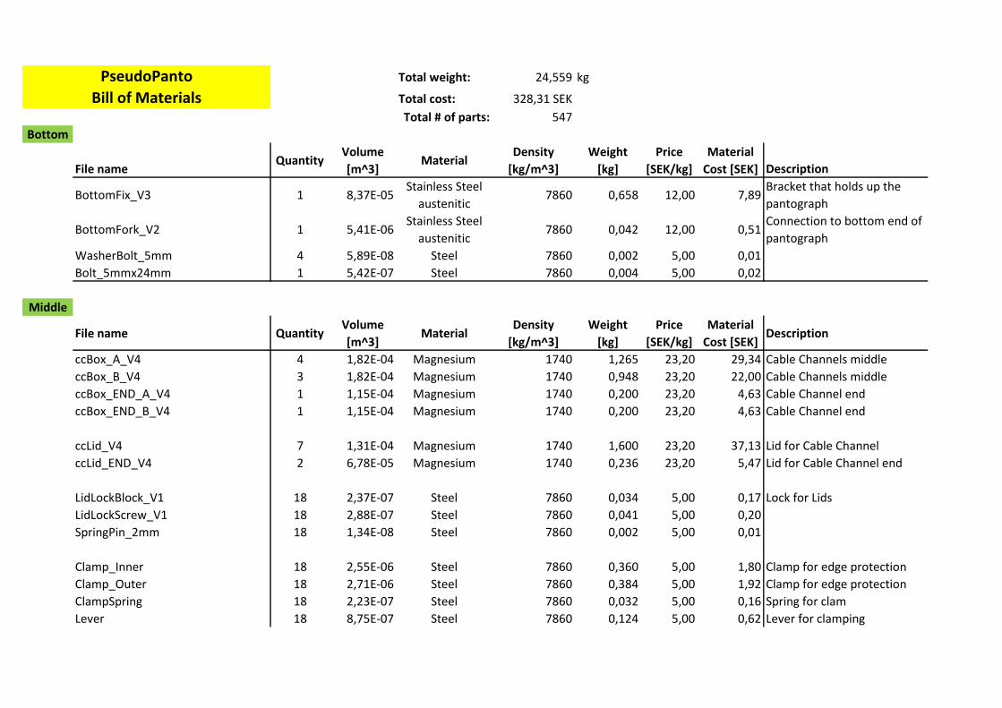
Total weight: 24,559 kg
Total cost: 328,31 SEK
Total # of parts: 547
Bottom
File nameQuantity
Volume
[m^3]Material
Density
[kg/m^3]
Weight
[kg]
Price
[SEK/kg]
Material
Cost [SEK] Description
BottomFix_V3 1 8,37E-05Stainless Steel
austenitic7860 0,658 12,00 7,89
Bracket that holds up the
pantograph
BottomFork_V2 1 5,41E-06Stainless Steel
austenitic7860 0,042 12,00 0,51
Connection to bottom end of
pantograph
WasherBolt_5mm 4 5,89E-08 Steel 7860 0,002 5,00 0,01
Bolt_5mmx24mm 1 5,42E-07 Steel 7860 0,004 5,00 0,02
Middle
File name QuantityVolume
[m^3]Material
Density
[kg/m^3]
Weight
[kg]
Price
[SEK/kg]
Material
Cost [SEK]Description
ccBox_A_V4 4 1,82E-04 Magnesium 1740 1,265 23,20 29,34 Cable Channels middle
ccBox_B_V4 3 1,82E-04 Magnesium 1740 0,948 23,20 22,00 Cable Channels middle
ccBox_END_A_V4 1 1,15E-04 Magnesium 1740 0,200 23,20 4,63 Cable Channel end
ccBox_END_B_V4 1 1,15E-04 Magnesium 1740 0,200 23,20 4,63 Cable Channel end
ccLid_V4 7 1,31E-04 Magnesium 1740 1,600 23,20 37,13 Lid for Cable Channel
ccLid_END_V4 2 6,78E-05 Magnesium 1740 0,236 23,20 5,47 Lid for Cable Channel end
LidLockBlock_V1 18 2,37E-07 Steel 7860 0,034 5,00 0,17 Lock for Lids
LidLockScrew_V1 18 2,88E-07 Steel 7860 0,041 5,00 0,20
SpringPin_2mm 18 1,34E-08 Steel 7860 0,002 5,00 0,01
Clamp_Inner 18 2,55E-06 Steel 7860 0,360 5,00 1,80 Clamp for edge protection
Clamp_Outer 18 2,71E-06 Steel 7860 0,384 5,00 1,92 Clamp for edge protection
ClampSpring 18 2,23E-07 Steel 7860 0,032 5,00 0,16 Spring for clam
Lever 18 8,75E-07 Steel 7860 0,124 5,00 0,62 Lever for clamping
PseudoPanto
Bill of Materials
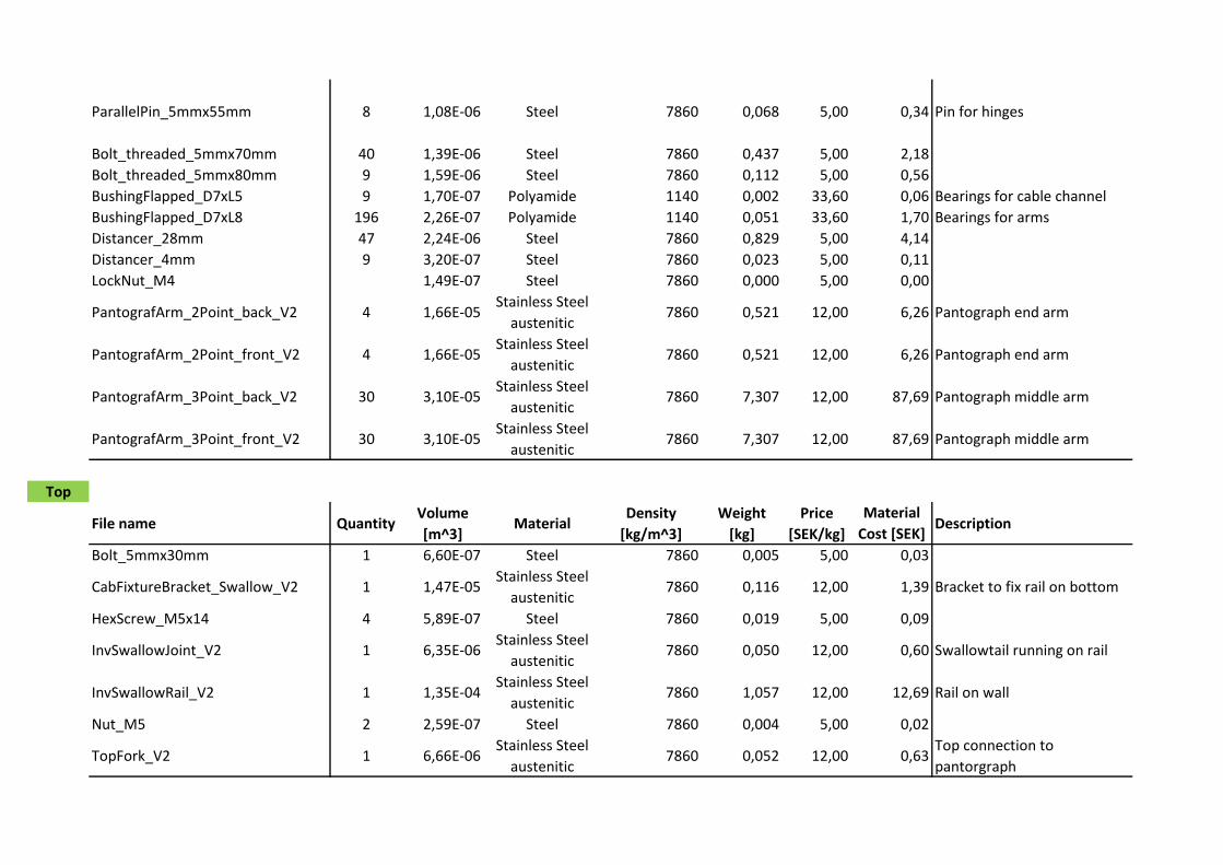
ParallelPin_5mmx55mm 8 1,08E-06 Steel 7860 0,068 5,00 0,34 Pin for hinges
Bolt_threaded_5mmx70mm 40 1,39E-06 Steel 7860 0,437 5,00 2,18
Bolt_threaded_5mmx80mm 9 1,59E-06 Steel 7860 0,112 5,00 0,56
BushingFlapped_D7xL5 9 1,70E-07 Polyamide 1140 0,002 33,60 0,06 Bearings for cable channel
BushingFlapped_D7xL8 196 2,26E-07 Polyamide 1140 0,051 33,60 1,70 Bearings for arms
Distancer_28mm 47 2,24E-06 Steel 7860 0,829 5,00 4,14
Distancer_4mm 9 3,20E-07 Steel 7860 0,023 5,00 0,11
LockNut_M4 1,49E-07 Steel 7860 0,000 5,00 0,00
PantografArm_2Point_back_V2 4 1,66E-05Stainless Steel
austenitic7860 0,521 12,00 6,26 Pantograph end arm
PantografArm_2Point_front_V2 4 1,66E-05Stainless Steel
austenitic7860 0,521 12,00 6,26 Pantograph end arm
PantografArm_3Point_back_V2 30 3,10E-05Stainless Steel
austenitic7860 7,307 12,00 87,69 Pantograph middle arm
PantografArm_3Point_front_V2 30 3,10E-05Stainless Steel
austenitic7860 7,307 12,00 87,69 Pantograph middle arm
Top
File name QuantityVolume
[m^3]Material
Density
[kg/m^3]
Weight
[kg]
Price
[SEK/kg]
Material
Cost [SEK]Description
Bolt_5mmx30mm 1 6,60E-07 Steel 7860 0,005 5,00 0,03
CabFixtureBracket_Swallow_V2 1 1,47E-05Stainless Steel
austenitic7860 0,116 12,00 1,39 Bracket to fix rail on bottom
HexScrew_M5x14 4 5,89E-07 Steel 7860 0,019 5,00 0,09
InvSwallowJoint_V2 1 6,35E-06Stainless Steel
austenitic7860 0,050 12,00 0,60 Swallowtail running on rail
InvSwallowRail_V2 1 1,35E-04Stainless Steel
austenitic7860 1,057 12,00 12,69 Rail on wall
Nut_M5 2 2,59E-07 Steel 7860 0,004 5,00 0,02
TopFork_V2 1 6,66E-06Stainless Steel
austenitic7860 0,052 12,00 0,63
Top connection to
pantorgraph

C.6. MATERIAL DATABASE CHARTS APPENDIX C. TECHNICAL ANALYSIS
C.6 Material Database Charts
PseudoPanto
Price*Density
100000 200000 500000
Yo
un
g's
mo
du
lus (
GP
a)
120
140
160
180
200
220
240
260
280
Stainless steel, martensitic, Custom 465, wrought, H1000
Stainless steel, ferritic, AISI 430, wrought, annealed
Stainless steel, ferritic, AISI 429, wrought, annealed
Stainless steel, austenitic, AISI 205, wrought, annealed
Figure C.8: Pantograph arms: Young’s modulus over price*density
Density (kg/m^3)
1500 1600 1700 1800 1900 2000 2100 2200 2300 2400 2500 2600 2700 2800 2900 3000 3100 3200
Fra
ctu
re t
ou
gh
ne
ss (
MP
a.m
^0
.5)
10
20
50
100
Polyester SMC (30% glass fiber, self-extinguishing)
Polyester SMC (25% glass fiber, self-extinguishing)
Magnesium, commercial purity
Polyester SMC (50% glass fiber, self-extinguishing)
Figure C.9: Cable channels: Fracture toughness over density
32

C.6. MATERIAL DATABASE CHARTS APPENDIX C. TECHNICAL ANALYSIS
Pri
ce
* D
en
sit
y
40000
60000
80000
100000
120000
140000
160000
180000
Magnesium, commercial purity
Polyester SMC (25% glass fiber, self-extinguishing)
Polyester SMC (30% glass fiber, self-extinguishing)
Figure C.10: Cable channels: Price*density
33
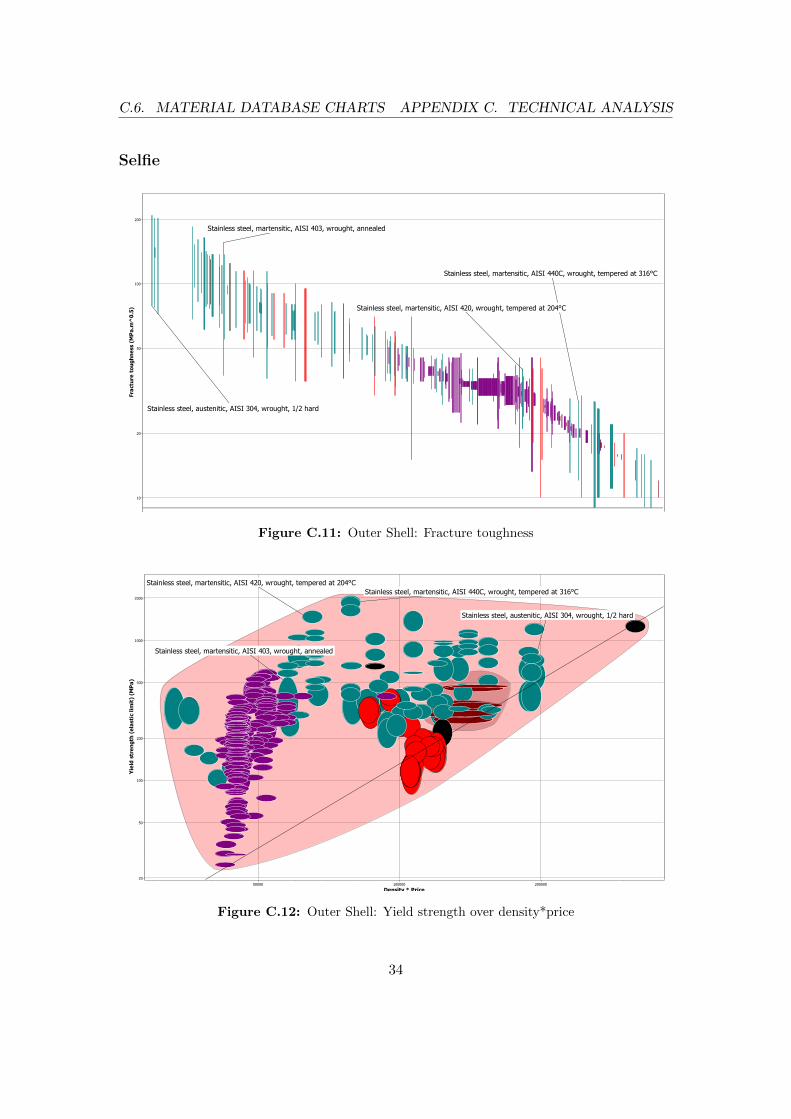
C.6. MATERIAL DATABASE CHARTS APPENDIX C. TECHNICAL ANALYSIS
Selfie
Fra
ctu
re t
ou
gh
ne
ss (
MP
a.m
^0
.5)
10
20
50
100
200
Stainless steel, martensitic, AISI 440C, wrought, tempered at 316°C
Stainless steel, martensitic, AISI 420, wrought, tempered at 204°C
Stainless steel, austenitic, AISI 304, wrought, 1/2 hard
Stainless steel, martensitic, AISI 403, wrought, annealed
Figure C.11: Outer Shell: Fracture toughness
Density * Price
50000 100000 200000
Yie
ld s
tre
ng
th (
ela
sti
c l
imit
) (M
Pa
)
20
50
100
200
500
1000
2000
Stainless steel, martensitic, AISI 440C, wrought, tempered at 316°C
Stainless steel, austenitic, AISI 304, wrought, 1/2 hard
Stainless steel, martensitic, AISI 420, wrought, tempered at 204°C
Stainless steel, martensitic, AISI 403, wrought, annealed
Figure C.12: Outer Shell: Yield strength over density*price
34

C.6. MATERIAL DATABASE CHARTS APPENDIX C. TECHNICAL ANALYSIS
De
nsit
y *
Pri
ce
20000
50000
100000
200000
500000
1e6
2e6
PF (cotton filled, impact modified, molding)
PPO/PS alloy (30% glass fiber)
Figure C.13: Plug and Antiplug: Density*price
35