alternating current distribution in cylindrical conductors · 280...
TRANSCRIPT

SS09
ALTERNATING CURRENT DISTRIBUTION IN
CYLINDRICAL CONDUCTORSBy Chester Snow
ABSTRACT
The fundamental equations of Maxwell for the scalar and vector potentials
4> and A are simplified by an approximation which is valid from the lowest to
the highest (radio) frequencies. This approximation is due to the difference in
the order of magnitude of the electrical conductivity of dielectrics and conductors.
The case of N conducting cylindrical groups surrounded by any number of
dielectrics is discussed and forms of solution obtained for 4> and A which are
proportional to e-vt—n- representing a simple possible type of propagation along
the cylinders. These lead to general formulas for the coefficients of leakage,
capacity, resistance, and inductance (all of which are functions of the frequency
in the general case) as well as expressions for the attenuation and phase velocity.
The mean energy relations are also expressed in terms of these coefficients.
Application is made to the case of two circular cylinders of different conductivity,
permeability, and radius, surrounded by a homogeneous, slightly conductive
dielectric. Asymptotic formulas for the alternating current resistance R andinductance L of the line at high frequencies are obtained, which, together with
the exact expressions for the coefficients of leakage and capacity, lead to high-
frequency expressions for the attenuation and phase velocity. These are all
functions of the frequency due to the fact that the current distribution is notuniform in the conductors.
CONTENTSPage
I. Introduction—Statement of problem 278
II. Fundamental equations 278
1. Type of waves—The propagation constant y 278
2. General approximations 279
3. Differential equations and boundary conductions for <j> and A. 281
III. The complex scalar potential <£ 284
1. Uniqueness of a solution 2842. Existence and uniqueness of a generalized Green's function
G 2863. The existence of <j> and its integral representation 2894. Properties and physical interpretation of the partial poten-
tials<f>D 291
5. The complex coefficients of leakage and capacity 294
IV. The complex vector potential A 295
1. Existence and properties of a magnetic flux function MJ 2952. Integral equations for A and E 2973. Existence and uniqueness of a solution of (36) 298
4. Other methods of solving the integral equation (36) 301(a) By normal functions 301(b) Method of successive integration at low frequencies 303(c) Method of harmonic analysis 304(d) Mixed method 304
5. Form and properties of the solution 3056. Coefficients of resistance and inductance 311
277

278 Scientific Papers of the Bureau of Standards ivoi.w
PageV. The propagation constant 7. Attenuation and phase velocity 313
1. Determinantal equation for 7 3132. Determination of constants to fit terminal conditions 3163. Special cases 316
(a) Case of two conductors 316
(b) Uniform proximity effect 317VI. Energy relations and mean values 318VII. Examples and applications 321
1. Case of two conductors with circular symmetry 321
2. Case of two circular, cylindrical conductors of different con-
ductivity, permeability, and radius, surrounded by a homo-geneous, slightly conducting dielectric. Mixed method. _ 323
(a) First and second approximations at high frequency.
Asymptotic formulas for R, L, and 7 with anyspacing 328
(b) Special case. Circular cylinder parallel to semi-infi-
nite plane of finite conductivity 333
VIII. Summary 336
IX. Index of principal symbols 337
I. INTRODUCTION—STATEMENT OF PROBLEM
A knowledge of the mode of propagation and distribution of alter-
nating current in a cylindrical system is important, for such currents
are used in practice, and, moreover, the propagation of an arbitrary-
type of wave or "transient" may theoretically be found in terms of
the periodic solution by the use of Fourier's integral or by complexintegration. 1 In working out such distinct problems as that of
propagation along parallel wires where the dielectric extends to
infinity, and along a cable system where a conductor extends to
infinity, a number of formal similarities become evident. It may be
difficult to see just how general are these similarities if the initial
formulation of the problem is not sufficiently general. Some of the
approximations to be made are common to all problems of this type.
Moreover, the connections between the field vectors and such physical
concepts as resistance, inductance, and capacity may be made in a
manner which is quite inclusive. In this paper a discussion of the
general problem is undertaken in the hope that it may prove useful
in outlining the procedure or forecasting the results in particular
problems of this type.
II. FUNDAMENTAL EQUATIONS
1. TYPE OF WAVES—THE PROPAGATION CONSTANT 7
If all the conductors and dielectrics have their generating lines
parallel to the z axis, the electric vector may be represented by the
real part of Ee lpt~^z and the magnetic induction by the real part of
1 Thornton C. Fry., Phys. Rev., p. 115; August, 1919.

Snote] A. C. Distribution in Cylindrical Conductors 279
Be lpt~'** where p is 2t times the frequency, and 7 is the complex
propagation constant which may be written
7 = 6 +% pT (1)
The real quantities b and V represent the attenuation constant
and phase velocity, respectively, of this type of wave. There will
be a finite number of types of waves or values of 7 possible for a
given system, and we shall first consider the case where only one
type is present. It will be more convenient to deal with the complex
scalar and vector potentials 4> and A, respectively, and to derive
E and B from them by the relations
E=-V(j>-ipA}B = curl A = l
xH\ (2)
The electromagnetic cgs system of units will be used throughout
with the exception of the dielectric constant Tc, which will be taken
in electrostatic cgs units. The electrical conductivity being X, andthe ratio of the units being c = 3 X 10¹⁰
, the Maxwell equations
ipJc^curl B = Att/j. ( X
curl E= —ipBAire) E Div# =
Div E=0\(3)
require that
v*.+»u.-f|
V2Ay + ?i2Ay
= dxdy
dxV2Az +h2A z=-^=-yX
d2 d2
Where V2^+^-2
l2 = y2 -
dA,
Airip/j(}ipk\Aire2)
XdA _. A , 7
2 "
dx dyyAz+
h24>
%p
(4)
Conversely any pair and A which satisfy these equations (4) andgive continuity to the tangential components of E and H will give
the correct field vectors.
2. GENERAL APPROXIMATIONS
It will be assumed that 7 is a small quantity of the order of - (firstc
order). In all materials Tc is of the order of unity, and hence the
complex conductivity a, defined by
->+£ (5)
will be very approximately equal to X in conductors; that is, a finite
magnitude (for copper X= 0.0006).

280 Scientific Papers of the Bureau of Standards [Voi.a
In dielectrics X is of the same order, or even smaller than the term
7~5 # Thus for gutta-percha X=10—2i and fc = 4 so that 43 = ^4-
It is therefore evident that for a range of frequency from one cycle upto the highest X will not be greater than the second order term
~r—? even if the dielectric is ten thousand times a better conductor47TC2
than gutta-percha, and consequently the complex conductivity will
be a second order infinitesimal in all dielectrics. For the sake of the
most general results we shall assume that X may be of the same order
as j—.j or 72
. The magnetic permeability n will have the value 1 in
all dielectrics and in nonmagnetic metals.
The cause of the wave is assumed to be in certain electromotive
forces applied to the terminals of the conductor at, say, z = and
z= l, where the cylindrical conductors are connected by networks of
known impedances. The simple type of wave here proposed could
not exist, strictly speaking, if the cylinders were not infinitely long in
both directions. However, we are here concerned with engineering
rather than optical applications, so that we may assume that the
cylinders are so long that the regions of space in the neighborhood of
the terminals, where this simple type of wave is departed from, are
negligible compared to the regions between the terminals where it is
sufficiently correct. Therefore, we may ignore these terminal varia-
tions of field or we may consider the term "end impedances" suffi-
ciently elastic to include them. We shall assume that there is nothing
analogous to these applied electromotive forces in a magnetic sense;
no applied " magnetomotive forces " tending to magnetize the cylinders
in the z direction. Hence, the component of magnetic field in this
direction Hz will be everywhere infinitesimal, since it could only be
produced by the xy components of current which will be infinitesimal
in the dielectrics and also in the conductors since the normal com-
ponent of current in conductors must be continuous with its value
outside. Hence, Ax and Ay will be negligible. We may, therefore,
understand A to mean the z component Az in all that follows, since
the others are negligible.
The first approximation to the solution will, therefore, lead to
d<f>Ex — — =— j> dAx dx -dx=5
E"= -¥y *,--%
dy
3
dx
Ez=E=- d*z-iVAz = y<l>-i?A Bz =
which hold at all points in the xy plane.
(6)

Snow] A. G. Distribution in Cylindrical Conductors 281
3. DIFFERENTIAL EQUATIONS AND BOUNDARY CONDUCTIONS FOR4> AND A
The electric component Ez (which will be designated by E from
now on) is of finite order of magnitude everywhere and is continuous
at all boundaries. Since E=y<l>— ipA, it follows that A and y<$> are
also finite. If 4> and A are continuous at all boundaries, the con-
tinuity of E will be assured. Since Ex and E7 are negligible in con-
ductors, <f> must have a constant value at all points in each conducting
section. Let <£ = cn at all points in the plane section SQ (z = constant)
of the 7ith conductor or group of conductors in contact. Suppose there
are N such groups. The tangential component of the electric field
in the xy plane will be zero (and hence continuous) at all boundaries
between a dielectric and conductor or between two conductors. It
will also be continuous at boundaries between two different dielec-
trics if is continuous there. At such surfaces the conservation of
electricity, or solenoidal property of the total electric current, requires
f\th
that o r-be continuous. Since a is a second order quantity, the last
of the equations (4) reduced to V2tf>= 0. Similarly at the boundary
between two materials of different magnetic permeability, the con-
tinuity of Ha demands that
be continuous. The continuity of Bn is assured by the continuity of
A T> dAA since Bn = -^—ds
Therefore, the differential equations which <i> and A must satisfy are
(a) V2<£= everywhere
(b) tf>= cn on the section Sn of the nth conducting group
(c) <t> is continuous everywhere51
(d) a — is continuous at the boundaries between twodn
different dielectrics
(e) ( r2 v-) exists for all directions of r
r= oo \ dr /
(a) V2 A = in dielectrics
= 47ripjuX ( A — 4-) in conductors
(jb) A is continuous at all boundaries
(c) - ^r— is continuous at all boundariesix on
{d) (r2-7T- ) exists for all directions of r
r = co \ dr J
M7)
Y (8)

282 Scientific Papers of the Bureau of Standards [Voi.ni
The relation (8a) follows from (4) . The conditions at infinity (7e)
and (Sd) are derived as follows:
Let 7n denote the total z component of current through the section
SD of the nth conductor (or nth group of conductors in contact).
The set of closed contours or artificial boundaries, shown bydotted lines in Figure 1, are drawn so that each artificial boundary
incloses a homogeneous material. In the case of materials extending
to infinity in the xy plane, the artificial boundary is closed by arcs
of a circle with center at some finite point and indefinitely large
Fig. 1.
—
Plane section of cylindrical media (z— constant) showing positive directions
of normals and line-elements in each region
(Full lines are natural boundaries. Dotted lines are artificial boundaries)
radius. The natural boundaries are shown by full lines. Thenormal to the boundary is taken in each medium pointing toward
the boundary, and the positive direction of an element ds of an
artificial boundary curve is such that in going around this contour
in the* positive direction the homogeneous medium encircled is on
the left hand. Thus the directions of n and ds are related like those
of the x and y axes, respectively. With this understanding, the
statement of the conservation of electricity applied to the n th con-
ductor is
7/D = Jad
d*dsa n=l, 2, 3 N (9)

snow\ A. C. Distribution in Cylindrical Conductors 283
where the integral is taken around any closed curve in the dielectric
which encircles this conductor only, the normal n pointing toward
the conductor.
Since <£ and a -^ are continuous and V2</> = in every dielectric, it
an
follows thatJa— ds = taken over any closed curve which does no
encircle a conductor. Consequently by (9)
^ r ^ f d(f> , limit f2ir
d<f>
72/,* C d<f> , limit f 2ir d$ ,_
=2 « -^ dsa = - r\ a-^-dOt^\J on r=oo J dr
where r is the radius of a circle with some finite point taken as center.
Since the terminal apparatus located in finite portions of the planes
2 = 0, and z = l are assumed to have no mutual capacity or coupling
with any of these cylinders, it follows that the sum of the currents
entering either end must be zero at every instant, so that
S/n = (10)n=l
Hence, the r -^- must be zero. But if we assume that the den-» /•= oo dr
sity of surface change on the natural boundaries is finite and falls
off so rapidly as the point on the boundary moves off to infinity
that the integral which defines its logarithmic potential is convergent,
then it follows that v~ must vanish in such a manner that r2 v~dr r= co dr
exists which is the condition (7e).
Similarly, it is assumed that the density of current (surface den-
sities of molecular currents on boundaries or magnetic surface
charges) are so distributed that their logarithmic potential exists,
dAand if r -^~ vanishes it must vanish canonically. The definition of
current takes the form
"f£&. (ID1
47rJ(
the integral being taken in the dielectric as in (9) . A similar reason-
ing leads to the condition (8d).
In the next two sections it will appear that the conditions (7) and(8) are necessary and sufficient to uniquely determine
<t>and A in
terms of the potentials ctc2 cN . These solutions of (7) and
N(8) will makeS ln = 0, which is reciprocal with the requirement that
r -5- and r =— shall vanish at infinity and in such a manner thatdr dr J
39058°—25 2
1

284 Scientific Papers of the Bureau of Standards [voiso
Ir2-^- and r2-^— shall exist. If no conductor extends to infinity,
then<t>and A are harmonic and the values of <£(«) and A(oo) will
be determinate, since one can not arbitrarily assign both the value
of the harmonic function and of its normal derivative at infinity
(if the c's are all arbitrary). In the case where a conductor, say,
the Nth, extends to infinity, then A and E will not be harmonic in
this conductor but will satisfy
V2 A-4t tv ipa ^1 = = v2 E-4 rfipa Esince
<t>(xN yN)-<£ (oo) = 1-1 =
if xNyN is on this conductor. Consequently, the vanishing of
r -z- I and hence r -r-Jbrings with it the fact that both A and E
mush vanish at infinity.
Whether either of the finite constants <f>(oo) or A(<x>) have the
value zero is a question without physical significance, since the x
and y components of electric and magnetic field will vanish properly
at infinity. But the linear combination y4>(°°) — ipA(co) has the
physical significance £'(oo)[=£'2 (eo)]. Consequently, we must con-
clude that for the type of wave assumed the first approximations
here attempted will give a definite value to E(co) which can not be
arbitrarily assigned the value zero. As a matter of fact, it will be
found that E(co) will not have the value zero in the case where one
conductor of finite section surrounds all the others. Even in this
case the formal solution we shall obtain will give the first approxi-
mation—that is, the finite terms—to the current distribution in con-
ductors. A further approximation would not appreciably affect
the value of E in conductors but would give a function Ez which is
not strictly harmonic in the dielectric and hence which vanishes at
infinity since -~- must do so.
In case more than one conductor extends to infinity we shall
assume that they are at the same potential and may be treated as
one group of conductors in contact. This avoids the case where two
conductors have infinite coefficients of capacity or leakage per unit
length.
III. THE COMPLEX SCALAR POTENTIAL
1. UNIQUENESS OF A SOLUTION
If the complex values cu c2 , . . . . cN which <j> must assume on the
conductors are arbitrarily assigned, there can not be more than one
function<f>
satisfying the conditions (7). If there were another,
their difference 4>' + i<j>" would satisfy all these conditions and van-

snow] A. G. Distribution in Cylindrical Conductors 285
ish on each conductor, where <j>' and <f>" are real. The boundaryconditions {Id) imply the two real relations
dn^A2
dn2 4ttc2Vx
a/ii2 dnjX^ + X
d4>"| xW _ V
dnx
2 dn2 4u-c^Xl^ r
'
* '^i?1 dn^** dn')
Also <j>' and #" are harmonic within each dielectric section Sj and
Wr(ie
„ limitWr<2e=()
J * r=coJdr
2r 2x
limit f 3^)' _Jrk _ limit f d<£
r= co
and
/('£-"£>-<>taken around the artificial boundary of #j or only around that part
of it which is adjacent to another dielectric since <f>' and #" vanish
at conducting boundaries, and the integral vanishes for arcs of the
circle at infinity.
By the use of Green's theorem it is easy to show that
Summing all such equations for the entire dielectric region of the xy
plane gives
where the double integral on the left extends over the entire dielectric
region, the line integrals on the right are taken around all the closed
artificial boundaries of all the dielectrics. The terms corresponding
to the conducting part of these boundaries vanish because <f>' and <j>"
are zero there. The terms corresponding to the boundaries between
two dielectrics may be written by virtue of the above boundaryconditions in the form
AK*£-*"&>over both sides of all the artificial boundaries between two dielectrics,
and this has been shown to be zero. Hence, <j>' and <j>" must be con-

286 Scientific Papers of the Bureau of Standards [voiso
stant over the entire dielectric region, since they are continuous there.
They vanish on conductors and hence </>' = <j>" = 0, which shows that
there can not be more than one function (j> which satisfies the condi-
tions (7).
2. EXISTENCE AND UNIQUENESS OF A GENERALIZED GREEN'SFUNCTION G
To find whether it is possible for any function <j> to exist which
satisfies the condition (7), and if so to obtain an integral representa-
tion of <t>, we may make use of a generalization of Green's function
G (xyto) , which may be regarded as the potential at any point xy
in the dielectric region, when there is a line source of unit strength
(per unit length along z) which is parallel to z, at some fixed point
to in the dielectric region, and when all the conductors are kept at
zero potential and all together receive the unit current from the line
source.
The properties of this function are
(a) \^~i+^~i) G(xy%r))=0 where xy is a point within any dielectric
section.
(b) 6 (xyto) and a (xy) ^- G (xyto) change continuously when the
point xy moves across the boundary line between two dielectrics.
(c) G (xyto) vanishes when the point xy moves up to a conducting
boundary of the dielectric region.
(d) When the point xy approaches the fixed point to, G (xyto) becomes
infinite in such a manner that it differs from p-—,„ f bv a47TO. (frj)
J
finite quantity. The strength of the source is I a— - ds taken
around an infinitesimal circle with center at to, and is thus equal
to 1, if m is drawn toward the circle, on the outside. This repre-
sents the efflux of electricity from the line source per second per
unit length along z (leakage and displacement current together).
(e) When the dielectric region extends to infinity, if xy moves off
to infinity in any direction in the xy plane (to being a fixed finite
point), then -^- vanishes (so that the _ r 2 -=- (xyto) exists).
Hence, G takes on the asymptotic form G (xyto) = G( co to) + terms in
- and higher. The constant (z(oo^) is calculable, not assignable.
From these properties it is easily shown by applying Green's
theorem to the two functions G(xyx'y') and Gfax'y'), where xy
and to are any two distinct points whatever in the dielectric region,

snow] A. C. Distribution in Cylindrical Conductors 287
that this function is a symmetrical one of the two points; that is
G(xyttv)=G(Zr,xy). (12)
This means that the potential at xy due to a line charge at £t? will
have the same value as the potential at £77 due to a line charge at xy.
From this interpretation it is evident that (^« + v^) £= and
that if xy is a fixed point and £7? the variable, then G and a ^— will
be continuous.
If we apply the integral transformation
I
jav2GdSi= ja-^dss
to each homogeneous dielectric section Sj and sum for all of them,
excluding the point I17 by an infinitesimal circle, we find that
N2 I
a-^(xkykZri)dsk =dG
where the Tcth integral is taken around any closed curve in the
dielectric which encircles the &* conducting group only. This
merely states the fact that the total flow from the line source
goes into the conductors and there is no flow to infinity.
To prove the existence and uniqueness of such a function G having
the desired properties, we may begin by assuming that a Green's
function gixyfr) has been constructed for the entire dielectric
region as if it were homogeneous. In the case of a closed finite region,
this is usually effected by writing
gixyfr) = -^logrixyZv) +v(xy£r,)
d2v d 2vand choosing vixy^-q) as a function which satisfies ^ +^= in
1
X V
the region, and assumes the value ~— log r(x'y'^ri) when xy ap-
proaches the point x'y' on the boundary, thus making gixy^rj)
vanish when xy approaches the boundary point x'y' . The existence
and uniqueness of v is therefore a special case of the more general
problem of Dirichlet of finding a harmonic function which assumes
any assigned boundary values. Since the development of the
theory of Fredholm's integral equation it may be taken as satisfactorily
proven that a harmonic function exists and is unique if either
(a) Its value is assigned on all points of the boundaryor
(b) Its value is assigned on some parts of the boundary, and the
values of its normal derivative on all remaining parts.2
3 Cf. Volterra. Leoons sur les Equations Integrals, p. 126. Max Mason "Boundary Value Problems.
New Haven Math. Colloquium.
"

288 Scientific Papers of the Bureau of Standards [Voi.io
In the case of an unbounded region, the value of g(xy%rj) whenxy goes to infinity is not prescribed, but the condition is imposed
that _ m r 2-~- shall exist. This, together with the facts that g shall
be harmonic in xy and vanish on all the internal boundaries of the
region and become logarithmically infinite when xy approaches
£??, serves to uniquely determine g and hence determines the value
which it will assume at infinity.
If we apply Green's theorem to the two functions a(xy)G(xy£1ri1)
and a(xy)g(xy%ri) the point xy being the variable of integration,
we find if i^ is within the homogeneous dielectric section Sj and£77 in £k
-giZiVih) =
-fa[0(xyilVl)&l& _,(ly{,,^ffl)]&l
the integrals being taken around the artificial contours of the
corresponding dielectric section. The contour integral on the right
has the value zero if taken around any other artificial boundary of a
dielectric. Hence, adding all such terms to cover the entire dielectric
region we get
afoMMM) + S K(s) - «*(*)]Q^0l G O&ifc) ds =g^Mv) (14)
where the line integral is taken once over all the boundaries between
different dielectrics, the point s(xy) being the point of integration
on this curve. The values a^s) and a2 (s) correspond to the mediumon the left and right of the curve, respectively, at the point s. The.positive direction of ds may be arbitrary, but the direction of the
normal n must be such that nxand ds
xare related to each other
like the directions of the x and y axes, respectively.
The continuity of G, a »—
»
g and -^- have been used in obtaining
this equation. (The point s (xy) on the boundary s is an ordinary
point for Green's function g)
.
If the point (£77) now approaches a point s'(x'y') on the path of
the line integral from the left side the equation becomes
a, is') G (s%Vt)-
j^f*'>-^')
j q (8%Vi)
+/K (s)-a2 («)] |£ (»') G («&,,) ds = g i^x'y') =g fovOor
G (s% Vl ) + 2 f V'il"2^ P- ("0 G fe) ds --&&S20 . (15)

snow] A. C. Distribution in Cylindrical Conductors 289
The same result is obtained when £77 approaches s' (x'y') from the
right, since the contribution of the infinitesimal element of the line
integral at s' is now
This is found from the fact that the principal part of ~- (s£rj) becomes
If the characteristic determinant of the integral equation (15) does
not vanish, it suffices to uniquely determine Gist-tfJ at all points s
on the boundary curve, and hence by (3) at all points in the dielectric
region. To prove that this determinant can not vanish, we makeuse of the fact that if it does there must be at least one solution
Gois^rjj) not identically zero of the homogeneous integral equation
obtained by replacing the second member of (15) by zero; that is,
^ (*-t,%) +»/*$;*$ % fao «.(**) *-o. we)
But if this were the case we could construct a scalar potential func-
tion <£ (£f) for any point £77 within the dielectric region by the
formula
4>o (en) = -^yj*K to ~ a2 to] If;(»&) ^o (•{A) & (17)
which could not be identically zero in all parts of the plane.
From the property of Green's function g, it is evident that 4> (£tj)
will vanish when £77 moves up to any conducting boundary, will be
harmonic in £77 at all ordinary points. Also it is evident that a
-r-2 will be continuous at the boundaries between dielectrics, and
_ (r2 ~ ) will exist. Finally, if £77 approaches a point on the
boundary between two dielectrics, then the homogeneous integral
equation (16), which G is assumed to satisfy, will show that 4> also
is continuous there. Thus cj> possesses all the properties which havebeen shown sufficient to assure its nonexistence. Therefore, it maybe concluded that a function Gixyfy) and one only may be found.
3. THE EXISTENCE OF <t> AND ITS INTEGRAL REPRESENTATION
Assuming that the function of G has been constructed, we mayapply Green's theorem to the two functions <t>(xy) and G(xy^ri),
and obtain

290 Scientific Papers of the Bureau of Standards ivoi.so
if £77 is a point within the homogeneous dielectric section Sitthe
integration being taken around the artificial boundary of Sj. Applied
to any other dielectric section S, the theorem gives
-Ja [*(,y)^M-<?(ly{,)^](fe-o.
Adding the first expression to all the others of the second type so
as to include the entire dielectric region, it will be found that all the
integrals over the boundaries between two dielectrics cancel, because
of the continuity of <$> and a ^- on the one hand and of G and a ^~
on the other. Also the integrals G(xy^)-^- over the conducting bound-
aries of the region vanish because G vanishes there. The integrals
over the infinite circle vanish because rr- and r-ir- vanish atdr dr
infinity.
Hence, we obtain the integral representation
<»--£}* f.C^g^*,fc=i J onk
=ScAfe) (18)
where
fettris- faixy^^ ds*'
(19)
this integral being taken around any closed contour in the dielectric
region which surrounds the lcth group of conductors only.
The N equations of type (9), for the conservation of electricity
give N equations of the type
f dd> -, * C d<6k 7 ^, ,nn.
yln = a— dsn =Sck a 5— a«n=S ank ck (20)J onn ?c= i J cmn fc=i
where the complex coefficient ank is defined by
***!'£*• <21 >
where this integral is taken over any closed curve in the dielectric
region which encircles the n th group of conductors only. From this
definition and the definition (8) of k it follows that the coefficients
ank constitute a symmetrical array, that is
ank = akn (22)
This is seen by inserting the definition (19) of <£k in (21), letting xy
denote a point on or near the boundary of the conducting section Su
and £77 a point on or near the boundary of the conducting section Sk
ank : -jjdsAa(xy) a((,)d
-^ff-

snow] A. C. Distribution in Cylindrical Conductors 291
Since G(xyi-rj) = G(£nxy) this is easily seen to be identical with the
definition of akn .
The unique solution or integral representation (18) for 0(£tj) has
been obtained by assuming a function <j> to exist which satisfies all the
conditions in (7) of Section II. It remains to be shown that the
function #(£17) which is given by the right side of (19) does indeed sat-
isfy all these conditions, and that if each of the N currents IJ2 . . . . 7N
satisfies the equation of conservation of electricity (20) , the sum of
these currents will be identically zero, whatever the value of the Nconstant potentials c
xc2 . . . . cN or of 7.
To do this and to obtain an idea of their physical meaning we mayexamine the N partial potentials of type <£k (£??) defined by (19).
4. PROPERTIES AND PHYSICAL INTERPRETATION OF THE PARTIALPOTENTIALS 4> B
From the properties of G(xy^) it foUows that foiZn) has the
following properties
(«) (5 +|?)^ (^)=0
if £17 is any point not on a boundary. This is evident by differentiat-
ing under the integral sign twice with respect to £ and to ij which is
allowable since £77 is not a point on the line of integration. Since
it follows that
/ d2 d2 \\de
+df)
G{xy^)=0
d24>k ,
d$ k
d£2' drf
=0
(b) When £17 moves across any boundary between two dielectrics fad-rf)
changes continuously because G(xy^rj) is also a continuous func-
tion of £?? for any fixed value of xy.
(c) At such boundaries a -— is also continuous because of thedn
similar continuity of a — when xy is any fixed point.
(d) The _ (r 2 -~ ) exists when £17 goes to infinity in any direction
in the xy plane, because of the similar property of G (xy^rj) whenxy is a finite point.
(e) When & moves off to infinity in any direction in the xy plane
</>k(£i) will become constant, say <£ k (°°), which will not necessarily
be zero. From the definition (8) it is evident that <£ k (£?7) is equal
to the total conduction and displacement current (per unit length
along z) which flows into the Jcth conductor, from the unit line
39058°—25 3
292 Scientific Papers of the Bureau of Standards [voi.to
source at fa, when all the conductors are at zero potential and all
together receive the total current unity, from the line source. It is
thus evident that if these conditions are satisfied, that <j>^(fa)
will not, in general, vanish when fa goes to infinity. If there is
one conductor extending to infinity, the Nth say, then <£N (oo) will
he unity and n ( oo )==O, if n^N, since the infinite conductor will
in this case receive all of the current from the line source at fa
when the latter moves to infinity. The same statements are true
if <£N surrounds all the others.
(/) When the point fa approaches any conducting section Sn , then
</>k (fa) approaches zero if n^lc and 4>^{fa) approaches unity at the
boundary of conducting section Sk . This is evident from the
above interpretation of <t>)dfa) as the current into S k when there is
a unit line source at £17. When fa comes infinitely close to the
boundary of any conductor, the unit current will all flow from
the fine source into the conductor in its immediate neighborhood
and hence the flow into any other conductor will be zero.
Thus <£k possesses all the properties which we have shown are
necessary to make it unique and it may be determined by the methodsof harmonic analysis.
From these properties of each <£k it is evident that the function
<t>(fa) given by (18) does satisfy all the conditions (7) Section II.
It is the only one which exists.
The N functions 0^ . . . . <£N are not all independent for there
exists a linear relation between them:
NS *kttij)=l (23)
fc=l
This also follows from the interpretation of foifa) as current into the
section $ k , since altogether the N conducting sections receive the
current unity from the line source at fa, equations (19) and (13).
From (23) it follows that there are N homogeneous linear relations
existing between the coefficients ank . Thus operating on (23) by
J2wa^ sives
NS «nk = forfc = l, 2, 3, . . . N (24)
n= l
From this it is evident that It+ 1
2 + ... + 7N = identically
whatever the value of cv c2 , . . . . cN and 7. The last of the N equa-
tions (20) is not independent of the first N-l equations, but may be
derived from them by simply adding them together. The determi-

snow] A. C. Distribution in Cylindrical Conductors 293
nant of this array of coefficients vanishes and it is not possible to
solve this set of equations for all the c's in terms of the Ps.
Hence, when each $ k has been found, then if each of the N currents
satisfies the equation of conservation of electricity (20) the necessary
relation (10), that the sum of all the currents shall vanish, will be
automatically satisfied.
The physical meaning of </>k (^) follows from its properties. It
represents the potential at any point (£77) when the Jcih conductor
is at unit potential and all the others at zero potential in the presence
of the various conducting dielectrics, subject to the additional con-
dition that the whole flow out from the kih conductor goes into the
remaining ones, as there is no flow to infinity in the xy plane. This
is the meaning of the relations (23) and (24).
It is evident that </ik is, in general, complex on account of the sur-
face charges at the boundaries between two dielectrics. These
charges are eliminated from appearance by the use of 6 (xy^rj)
through which function their influence is exerted, so to speak. If the
dielectric were entirely homogeneous both as to its conductivity X
and its dielectric constant Tc, then the function <£k would be a real
electrostatic function, which would not involve X, Tc, or p, but woulddepend only upon the geometric configuration of the conducting
sections which bound the dielectric region.
More generally, if the ratio
V1*p*l
*1 *, a,1
4ttc2
V ATq «2 V 1 A„rf
is real, for every pair of dielectrics in contact, then each <j>k is real,
and involves the values of these real ratios, but not the frequency.
In particular, if all the dielectrics are nonconducting, this ratio is
real and <£k will not involve the frequency.
In general, the surface charges and their phases, at the bound-aries between different dielectrics, although they are eliminated
from consideration, are the cause of<f>being complex and involving
the frequency.
It is evident that if a real formula for </> k can be obtained for the
case of steady flow through the given dielectrics, with given conduc-
tivities XXX2 etc., then the complex solution <£ k may be
obtained by substituting in this expression the corresponding complexconductivities a
xa2 in place of their real values.
It is to be noted that <£k does not involve 7.

294 Scientific Papers of the Bureau of Standards [Voi.20
5. THE COMPLEX COEFFICIENTS OF LEAKAGE AND CAPACITY
The complex charge of free electricity Q a upon, and the leakage
current Gn from, the nth conducting group per unit length along z are
given by
n 1 f , d<t> ,* If, d4>k n
H*~TV&) kdn n
tfSn _fe
Ck 4~772J
* dn~n***
(25)
«nk = Gnk + if Cnk where
Consequently, if we resolve the complex coefficient ank into its real
and imaginar}^ componentsN
£nk = <?kn and2 6rnk =
(26)
NCnk = Ckn and2 Cnk =
4=1
The equation of conservation of electricity (20) takes the form
yh = G n + ipQ n = - s(^nk+*pCnkVk. (27)
By adding to this equation the identically zero quantity
N N N / \
-C n 23«nk= - S "ilk Ca= 221 ^nk+^Cnk )Cn
fc=l /t=l Jc=l\ /
it takes the form
yIn = G n +ipQ n = s(^nk + Z>CDkj(c„-C k
J(28)
which shows that the real coefficients Ga^ and Cnk where n^Jc are
coefficients of leakage and capacitance, respectively. The coefficients
Gnil and CnD do not occur in the form (28) and may be regarded
simply as the negative of the sum of all the other coefficients 6rnk
and CBk , respectively.
If the frequency is very low, or if the entire dielectric region is
homogeneous, or more generally whenever the functions 4> n are real,
6rnk and 6"nk will not be functions of the frequency and will have their
ordinary electrostatic significance since they are then defined by
It is evident that, in general, the formula (27) may be put in a form
similar to (28), namely,
T/D=S« nk (ck -cN) for w=l, 2, 3, N. (30)t=i

snow] A. C. Distribution in Cylindrical Conductors 295
IV. THE COMPLEX VECTOR POTENTIAL A
1. EXISTENCE AND PROPERTIES OF A MAGNETIC FLUX FUNCTION MLet s (xy) be any point on the boundary between materials of
different permeability. Let £77 and ^1 ?j 1be two other points not on
this curve. Consider the vector potential function whose x and ycomponents are zero, but whose z component has at the point £77
the value given by the logarithmic potential
M failVl) = M (1*7) [- 2 log r (toi) - 2JV (*)
dkg^sy^j ds (31)
where the direction of ds along the curve may be taken at pleasure,
but that of dn is that of the normal drawn toward the curve in the
medium on the left side. The integral represents the value at £77 of
the logarithmic potential of a double distribution of strength a (s)
upon the boundary curves where ^ is discontinuous. This is har-
monic and has continuous normal derivatives [(£77) being the variable
point] at all points. It also vanishes when £17 moves off to infinity.
It may also be written in the form
-2Ja(s)d lQg^> ds= -2
J ff (g)g^) ds-
where 6 (xy&) is the angle between the positive direction of the
x axis and the line drawn from s (xy) to £77.
Regarding ^^ as the fixed point and £77 variable; it is evident that
(whatever the function <r(s) so long as the integral is convergent), the
/ d2 d2 \function Jf^^) satisfies ( p+T-J M (£t7£
1 77 1)=0 and takes the
1-\
form —2n(j-ii) log rfaLr).) when £77 goes to infinity, and that —nr\ -ttM£*?) dn
M (£77^7?^ is continuous everywhere. The integral, however, is
discontinuous at the boundary curves, but if <r(s) can be so chosen
as to keep Mfa^ri^ continuous there, then it is evident that
^(iv^iVi) will represent a (s-component of) vector potential function
at £77 due to a steady unit current filament at £1i71
parallel to z, in
the presence of all magnetic materials.
This is evident since the normal component of the magnetic
induction derived from it is just -^— and this is continuous if M is so.
The tangential component o' B divided by (x, that is of H, is »
—
and this will also be continuous. If we compute the line integral
around an infinitesimal circle with center at ^77, the result is 4tt.

296 Scientific Papers of the Bureau of Standards [Vol. so
To determine the density a(s) we must express the fact that
-3/(£'7£i'?1 ) approaches the same value when the point £77 approaches
a point s' (x'y') on the boundary curve first from the left and then
from the right. In the first case the equation gives, if jux(s') is
the value on the eft, n2 (s') on the right of the curve at s'
2/t (si) g r (s €i>?i) +tt<t(s')+ \ <r(s) —^— ds.
In the second case
—2M (gV g r (8 toJ -tto-(s') +
Jo-(s) —^— ds.
Eliminating Mis'J-tfJ gives the integral equation
*(s>) + 1 ((^) , ^ <r{s) ds=- 1-(^±^) , log r(s'U)(32)^J VM1 + M2/S #S 7TVMX-M2/S 6 1X
to determine the density of the double distribution <r(s). Thenucleus of this equation becomes infinite when s= s', but is in-
tegrable, and the equation may be reduced to one with a finite andcontinuous nucleus by multiplying by this nucleus and integrating
over the range. This equation uniquely determines the function <r
provided the Fredholm determinant is not zero.
That this can not be the case may be proven from the known fact
that when this determinant vanishes there is at least one solution
<r (s), not identically zero, of the homogeneous equation obtained
by placing the right side of the above equation equal to zero. Withthis function a (s) we could then form the potential v (£ri) for every
point fa by the formula
v (M = -2^v)J*o(s)dlOS
d
r^ds
(33)
This function v would satisfy ( ^ + r—2
\ v = at all points, and
- ^-° would be continuous everywhere and would vanish at infinity.
In addition, v itself would be continuous because of the assumed
property of the function <r (s) . Moreover, v could not be identically
zero in all sections of the plane. It is easy to show that in this case
by transformations similar to those previously used that
M(tMt)>=°the integral being taken over the entire plane, and since n is a real
positive value everywhere, and v is real, it is evident that v mustbe a constant everywhere, and hence zero since it vanishes at infinity.

snow] A. C. Distribution in Cylindrical Conductors 297
Therefore, the Fredholm determinant does not vanish and there is a
unique solution <r (s) and the function M i^tVi) rnay be uniquely-
determined.
By applying Green's theorem to the two functions M (xy^-q) and
M (xy^rjj we find that M is a symmetrical function of the twopoints xy and £?i in whatever magnetic media the two points maybe; That is
M(xyZT,) = M(toxy). (34)
In the special case where all 'the materials in space have the samemagnetic permeability M (xyfr) reduces to — 2/x log r(xy£r]).
2. INTEGRAL EQUATIONS FOR A AND E
By means of the function M we may formulate the conditions (8)
for A as an integral equation involving surface integrals over the
conducting sections, but free from boundary terms.
To do this apply Green's theorem to the two functions A(xy) andM(xy£f)) where |ij is some point within the section S
swhich may be
either a dielectric or conducting section. This point £77 being
excluded by an infinitesimal circle, the theorem gives
= A(£r)) if £17 is within Sj
= for all other sections.
Adding together all such expressions corresponding to the entire
xy plane, the line integrals over both sides of all boundaries between
different magnetic media cancel, because of the continuity of
A, M, — it— and r— The integral over the infinite circle gives the' ' ju dn m dn fe &
term A(oo). (However, it is important to notice at this point that
the same result would have been obtained if A were assumed to take
the asymptotic form A = A(co)+A' log r at infinity.) Replacing
V2A— -t— by its value — \(ipA — y<f>) from (8a) of Section II, gives, after
interchanging the notation of the points xy and £77
A(xy)+ipJj M(xy^rl)\(^A(^)-^M'j <fc&7=4(«o). (35)
Or since E=y<f> — ipA by (6)
E (xy) +ipffM (xyh) X (£77) E (£77) d^dr, = y<t> (xy) -ipA(^)
=F(xy)=y[(j>(xy)-4>(co)] + E(co) (36)
[Since E(oo) =7^(00) —ipA(os)]
where the integration extends over all conducting sections. Theequation must hold whether (xy) is a point in a conductor or in a

298 Scientific Papers of the Bureau of Standards ivoi.so
dielectric. Hence, after the value of E has been determined for all
points in conducting sections, this equation becomes an explicit
formula giving the value of E at any other point. As a matter of
fact, the value of E at outside points is seldom of practical interest,
and the value of E in conductors may be found without reference to
its value in dielectrics. All of the conditions (8) except the last
have been assumed in the derivation of (35) and (36), and it is
easy to show from the properties of M that if this equation is
satisfied all of these conditions will be fulfilled with the exception of
the last one, which requires that r -r-f or r— \ shall vanish canonically
Nat infinity, a condition which is reciprocal with the relation 2 In = 0.
i
This condition will, therefore, determine the value of A (» ) or E( oo )
.
The integral equation (36) has a unique solution given in the form of
a definite integral when the second member F(xy) is any function
given in all conducting sections which makes this integral convergent,
so that the undetermined constant E(co) which made its appearance
in (36) must be so chosen as a linear function of the N constants
cv c2) cN that 2 -^n (where In is defined by (11) Section II)
shall be zero whatever the values of cv c3 , . . . . cN . These constants
may then all be considered as arbitrarily assignable. It may be
noted that in case the Nth conductor extends to infinity the value of
E(co) must be zero since 7N is assumed to be finite. Also, in this
case <£N (» ) = 1 and n ( oo ) = when n^N. Consequently, the second
member of (36), namely F(xy), which has different constant values
on each conducting group, will have the value zero when xy is on
the Nth conductor, since
7[<H%yN)-4>N(°=)]+#(«)=Y[i-i]+o=o.
On any other conducting section S n it has the value yc a if n=4 N.
3. EXISTENCE AND UNIQUENESS OF A SOLUTION OF (36)
Multi; lying the expression (36)
[E{x'y')+ipffM{x'y'^) X (£„) E(fy,) d£ dv-F (x'y>)] =
by ipM (xy x'y') X {x'y') dx' dy' and integrating with respect of x'y'
over the entire range shows that if E satisfies (36) it must also satisfy
the equation
ip ff x oy) M (xv x'y') dx ' dy'-
(37)
[E {x'y') +ip fSMix'y'fr) X (£„) E (ft) # dv -F(x'y')] = 0.

snow] A. G. Distribution in Cylindrical Conductors 299
Conversely, if this equation is satisfied, we may show that the bracket
must be identically zero and, therefore, (36) will also be satisfied.
To prove this let the bracket be represented by h'(xy) +ih"(xy).
Then h'(xy) must be a real function such that
ffM(xyx'y') V (x'y') dx'dy' =
identically for all values of xy, and similarly for h". Denoting
this integral by V (xy) , it is evident that if V (xy) = identically then
V2 V (xy) = everywhere in the range. But V2 V (xy) = Airn (xy) h (xy)
as is seen by differentiation of the integral, and from the properties
of M. Consequently, h (xy) must be zero everywhere if h is such
that ff~h2dxdy exists. Therefore, the equations (36) and (37) are
reciprocal.
By making use of (36) the equation (37) may be written
E(xy) +fffdx'dy' M(xyx'y') X (x'y')ff M(x'y'fr) X (£„) E(fr) dtfr,
= F(xy) -ipffM(xy^) X (£„) F (fr) ^dV -
The second member of this equation will be finite even if the Ntb
conducting section extends to infinity, since F(xy) will vanish on
this section.
We may for the present limit the discussion to the case where aU
conducting sections are finite. The form thus obtained for the
solution then suggests methods of dealing with the equation with
open sections. With finite range the order of integration in the
preceding integral may be interchanged and the equation takes the
form
E(xy)+fffN(xyZv)M$v) Efo) d^dv =f(xy)
= F(xy)-ipffM(xyx'y') X (x'y') F(x'y') dx'dy f(39)
where the new nucleus
N (xyfr) = N (frxy) =ff M(xyx'y') M(frx'y')\(x'y')dx'dy' (40)
is not only symmetrical in the two points, but is everywhere finite
—
a property not possessed by M, which becomes logarithmically
infinite when the two points approach each other. The theorems of
Fredholm are applicable to this equation and show that if p is not a
root of the characteristic determinant, there is one and only one
solution.
E(xy)=F(xy) -ipffft (xyfrip) F(^) d£dr, (41)
where yi(xy£r)ip) = V ,. f is the resolving nucleus of the primitive
39058°—25 4

300 Scientific Papers of the Bureau of Standards [Voiso
equation and is given by Fredholm's formula. It satisfies the twointegral equations
Mixyx'y') X {x'y') — SSlixyx'y'ip)
=ipff Mixyfr) X (|t;) ft (itvx'y'ip) d^dv
=ipffM(frx'y') X (x'y'm (xyknip) d^dv . (42)
It is evident that N (xy,xy) is finite since
N(xy,xy)=ff[M(x'y'^)]2 ^(x'y')dx'dy'
and the surface element when x'y' is near the point £tj may be
written in the form
I dd I rdr\ - 2/z logr =87tm2(£'?)
Jr(logr) 2 dr
= 4717? (£»?)
e
2 log2 e-loge +2
and this vanishes with e, showing that the element of the surface
integral near the point £77 contributes an infinitesimal amount to the
integral.
If p were a root of Ds{ip) = 0, then N would become infinite and
the solution impossible in general. But it is shown that in this case
there must be at least one solution E (xy), which is not identically
zero, of the homogeneous equation obtained by placing the second
member of (9) equal to zero. This solution E (xy) would also satisfy
E (xy) +ipSfM(xytr,)Uto)Eo (frj)d&r, = 0. (43)
If we write E (a;?/) = E' (xy) + iE" (xy) where E' and E" are real
functions, and multiply this equation by
[E' (xy) -iE" (xy)]\(xy)dxdy
and integrate over the entire range, we obtain
SfHxy) [E' *(xy)+E>' (?(xy)] dxdy
+ pffdxdyffd^dv M(xy^)\(xy)\(^) [E' (^)E" (xy)-E' (^)E
(xy)l = -ipffdxdyffd^dv M(xytr,)\(xy)\(mE' ^v)E' (xy)
+ E" (^)E" (xy)]. (44)
The second member of this equation is a pure imaginary, the first
member real, hence each side must vanish. The second integral on
the left vanishes because of the symmetrical property M(xy^) = Mfaxy). Hence we must have
ff\(E'<? + E" ')ds = or E'o=E"o=Eo (xy)=0
and, therefore, no real value of p can be a characteristic constant for
the primitive integral equation. A unique solution exists for all real
values of p.
snow) A. C. Distribution in Cylindrical Conductors 301
4. OTHER METHODS OF SOLVING THE INTEGRAL EQUATION (36)
(a) By Normal Functions.—It is worth while to examine the
equation from the point of view of normal functions. The nucleus
N(xyx'y') is not only symmetrical and finite but it is definite, bywhich it is meant that there is no real function Ti(xy) whose square is
integrable (that is, such thatJ*J"h2 (xy)dxdy exists and is not zero),
which will make the integr&lJ'J'dxdy ffdx'dy' N(xyx'y')h (xy)h(x'yf
)
vanish. This may be proven by noting that
ffdxdyffdx'dy' N(xyx'y') h{xy) Wy')= ff\{kv)d^dy]ffM{xy^)Mxy)dxdyffM{x'y'^)Mx'y')dx'dy'
=ff X (&) d£ dr, [ffM (xyfr) h (xy) dxdyf
which is always >0 unless there is a function h for whichffM(x y^-q)
h(xy) dxdy = identically for all points £?? in the range. We have
just shown that no such function exists.
From this " definiteness " of N it is known that its characteristic
constants are infinite in number, real, and positive, and form a
denumberable ensemble of isolated points. To each such constant
rn2 there corresponds a normal function un {xy) which is a funda-
mental solution of the equation.
uD (xy)-Tn2J'fN (xy£rj) un (fr) d£ ^ =
The set of functions u^xy) ,u2 (xy) are infinite in number and
constitute a closed set of normal functions such that
Sfun(xy)um (xy)dxdy = if n^m= 1 if n = m
and the nucleus N(xy&) is equal to the uniformly convergent
series
iVW^*^'' (46)
An arbitrary function f{xy) may be developed in a uniformly con-
vergent series of these functions in the form
f(xy)=Sfnun (xy) (47)71=1
where the Fourier coefficient /„ is given by
fn =ff F{xy) un (xy) dxdy) (48)
00
provided, the series S/2n is convergent. Since the set of normal

302 Scientific Papers of the Bureau of Standards ivoi.so
functions is "closed" there is no function which is normal to all of
them; that is, orthogonal to N(xy^rf). The equation (39) may then
be written
E(xy)+f^^^-Jju D{^)M^)mv)d^drj ^f(xy) (49)
oo
= ^2fnUn (xy).71=1
In the simplest case, where X has the same value in all materials,oo
assume E{xy) = 2 Enun (xy) and substitute in (49). This givesi
S «b (xy) [~£n +^En -fj\ =m=l |_ T n J
giving
E = ^i+x£
and the solution is
j-,, ^Fnun (xy) _ C Cm . , , ^ un (xy)un (£r])
v =STT^" J JF(Mm ST^7~ (so)
T n T n
In the general case, where X has different constant values in dif-
ferent conductors, if we write
00
\(xy)E(xy)=52 b aun (xy)71=1
and00
E(xy) =2 Enun (xy)71=1
and substitute in the equation, we find
71=1 L T n J
which will be satisfied if we may make
Now
or
where
^ED + b a =T-^ for 71 = 1,2, 3 oo.
p2 P2
b n = I
J
u n (xy)\(xy) E(xy)dxdy
=1 I u n(xy)Mxy)ibEku k (xy)dxdy
oo
k=l
gnk=g kn- C I
x(Xy)u n (xy)u ]! (xy)dxdy.

snowi A. G. Distribution in Cylindrical Conductors 303
Hence, the constants En will be the solution of an infinite set of
linear equations
T2 °° T2 f^ Ea + ^2 gnk E* =T-^ for n = 1,2,3 N
or
(j2+9n) El + g12 E2 + g 13 E3 «£j&
J2
P29u Ei + fy+ff22j E2 + g23 E.
g31E,+g32 E2 + (^+ g33^j E3
=^J-
This set may be solved because its determinant can not vanish for
any real value of p.
In case X has the same constant value on all conductors
grnk = if n^Tc
#nn = X
and we obtain the previous formula.
In the case where a conductor extends to infinity, the range of
integration is no longer finite and the characteristic values of a finite
symmetrical nucleus would no longer constitute a set of isolated points,
but would become uniformly distributed along the real axis every-
where equally dense. The representation of an arbitrary function
in an infinite series of normal functions, over a definite range, wouldthen give place to its representation over the infinite range by a
definite integral of which Fourier's integral is an example. Instead
of a solution in an infinite series of normal functions, one may expect
a solution in the form of a definite integral.
(&) Method of Successive Integration at Low Frequen-cies.—It may be noted that the method of iterated integrations,
which is always applicable to Volterra's type of equation, may be
successfully applied to the present problem if the frequency is small.
This gives the solution in ascending powers of ip and is only applicable
for values of p less than the modulus of the first characteristic con-
stant of the primitive equation. The solution will be identical with
that obtained from the Maclaurin development of
in ascending powers of p. Although no real value of p can be a
root of D-x(ip) =0, nevertheless the Maclaurin development is
limited to the circle in the complex p plane, whose radius is less than
the modulus of the smallest complex root.

304 Scientific Papers of the Bureau of Standards [Voi.eo
(c) Method of Harmonic Analysis.—It seems probable that in
the majority of cases there will be less labor involved in solving the
differential equation with its boundary conditions by some sort of
series of harmonic functions, such as Fourier-Bessel expansions, than
in solving the integral equation for A (or E)
.
The differential equation for A suggests certain types of expansions
for A as a series of appropriate functions in each conductor or group
of conductors which will be normal functions for that section. If
there are groups of conductors in contact for which X or n have1 dA
different values, the continuity of A and of — -^— at such internal
boundaries will lead to certain relations between the coefficients.
The mutual influence which the conducting groups exert upon each
other across the intervening dielectrics may then be found by assum-
ing certain forms of expansion for A in the dielectric and by then
1 dAmaking A and - r— continuous at every boundary between con-
ductors and dielectric. This step may, however, be replaced bythe following process which avoids any reference to the dielectric.
id) Mixed Method.—Let xy be a point within any conducting
section, and with £17 as the variable of integration apply Green's
theorem to the two functions A (£17) and log r(xy^rj) for the entire
dielectric region. This gives
4(»)4/[^(h)ii5i«-,„g K*)^>=0where the integration is taken in the dielectric just outside the
conductors and around the complete boundary of all conductors.
1 dASince A and - -r— are continuous at such boundaries, this necessary
condition which A must satisfy becomes
where the integration is taken around the complete boundary of all
conducting groups as before but just inside the conductors. The
internal normal ni points toward the boundary. If the series for the
internal values of A at each conducting group be introduced into this
integral, the result must be identically true in whatever conducting
section the point xy may be. By expressing this fact, when xy is
in each group in succession, the required number of equations be-
tween the coefficients are obtained. This method is illustrated in
the case of two circular cylinders at the end of this paper.

snow] A. C. Distribution in Cylindrical Conductors 305
5. FORM AND PROPERTIES OF THE SOLUTION
The n functions o}t(xy), to2 (xy), coN (xy), which are defined as
the solutions of integral equations of type
wk (xy) + ifffM (xyfri) X (£77) cok (fri) d^dt\ = fa (xy) (52)
are all linearly independent, for if there were a relation of the formN2 ^k^k (xy) = the above equation, on being multiplied by h^, and
the sum taken for all values of Tc leads to
N N N2 frkWk (xy) +ifffM (xyfyi) X (&;)27W (to) d^dy =2 Mk (xy) .
fc=l fe=l s=i
yThe hypothesis leads to the conclusion that 2 hkfa (xy) = for all
values of xy in the range. But since fa(xy) =1 when xy is on con-
ducting section #k and equals when xy is on Su where n^Tt, it
follows that 7^ — h2
=^n = 0.
It is also evident that the only solution of
u (xy) + ifffM (xyfri) X (£77) a (£77) dJ&q = 1
isTV-
CO (xy)=2wk (xy).
The solution for E is therefore
iV
E (xy) =2 [YCk- ifA ( 00 ) ] Wk (xy) (53)fe=i
and
/n = 2[7Ck-ip^(»)&DiJ (54)
wherebn* = ff\o>kdSa (55)
the integration being taken over the section Sa of the nth conducting
group. The array of complex constants &nk is symmetrical; that is,
&Dk = frkn- (56)
To show this, multiply the equation for wk by \(xy)wn (xy)dxdy and
integrate over the entire range. This gives
ff X (xy) con (xy) cok (xy) <Zxdy
+ifff dxdyff d^drjM (xyfri) X (xy) con (xy) X (£77) cok (£7?)
= /*y X (xy) wn (xy) </>k (xy) dxdy =ff\wa dS* = 6kn -
306 Scientific Papers of the Bureau of Standards [Voi.to
If we multiply the equation for ua by \uk dxdy and integrate, the
right-hand side is &nk and the left side is easily seen to be identical with
the above on account of the symmetrical property M(xy£r)) = Mifrxy).
The constant A(<x>) must be so chosen that the sum of all the
currents In will vanish. If the expression (53) for E be multiplied
by \{xy)dxdy and the integration taken over all conductors, this gives
\Edxdy=2ln = =72ck \{xy)w ]L {xy)dxyJ J n=l k=l J J
—ip A(co) X 2 uk (xy)dxdy
orJV JV
7 2 2 &nkCk
= 7 2*k(»)ck (57)
(58)
ipjx (,<»;— Hj{<x> ) -\- yep { <x> j — jy-
jv
2 2&nk71=1 fc=l
whereJV
2&nkOr Ccol
M=1^klWJ jv JV
2 2&nsw=l s=l
which shows that
S*k(°=) = l.)t=i
In order that it shall always be possible to thus choose the constant
yl(») as in (57), so as to make 2 ^n = 0, the denominator in the
above formula for SJ'kX 00 ), namely,
jv jv r r2 2 J«k or US^k (xy)dxdym=l fc=l J J
must never be zero. To prove that this can never vanish let
JV
"(a*/) = 2 uk (xy)=u(xy) + iv(xy)fc=i
where w and v are real functions satisfying
u(xy)-pff M(xy£ri) X (f q)v (£17) <?{<Zq = 1
v (scy) +p/y M(xy£r,) \{£v)u (£17) cr
7^/?? = 0.
Multiply the first of these by \(xy)u{xy)dxdy , the second by\(xy)v(xy)dxdy, add the results, and integrate over the range.
This gives on account of the symmetry of Mff X (xy) [u2 (xy) +v2 (xy)]dx dy = ff X (xy)u(xy) dxdy
Now, if the sum in question were zero, then
ffkudxdy = ff\vdxdy =

snow] A. 0. Distribution in Cylindrical Conductors 307
and in this case the above relation would require that u and v and
henceN
«= S wk (xy)
be identically zero at all points of the range, which is never the
case since the functions cok (xy) are not linearly dependent. This
shows not only that the double sum in the denominator of (58)
never vanishes, but that its real part is always positive. Conse-
quently, it will always be possible to choose A(oo) by (57) and (58),
so that the sum of the currents will vanish. A similar treatment of
wk (xy) shows that the real part of 6 kk is positive and less than p ,n .•
Inserting the value of ipA(co) in the expression (53) for E{xy)
givesN N N
E(xy)=y 23 c kw k(xy)-7S <»s(xy) S^k(°=)c kft=l s=l fc=l
n r iv -|
=7S«k wk(sy)-*k(«>) S«8 (sy) •
t=i L »-i J
If we define the new set of functions Qv Q2,• .• • • fin fiN by
Mzy)=w k (xy)-*k(co)S ws (xy),£ = l, 2, • • • N (59)
then
£(xj/)=7SckQk (x2/). (60)
From this definition it follows that
ff\(xy)^(xy)dxdy = 0, Tc = l, 2, 3 • •- •. -N. (61)
SubstitutingiV
wk (xy) =flk (xy) +^k (co) S ws (xy)s= l
in the integral equation (52) for w k gives
Qk(xy)+ip/yjf(xy^)X(^)Qk (^)^^+^k (co) s o>s (xy)5 = 1
+ ipffM(xyZr,) X (I,) Ws (^) <Z|cZi7] = k (xy).
The bracket in the equation is just </>s (xy) and S <£s (zy) = 1.s= l
Hence, Qk (xy) is the solution of the integral equation
Ok(xy)+^yyJ/(xy€)?)X(^)fik(«'7)^J7 = *k(xy)-^ k (oo). (62)
308 Scientific Papers of the Bureau of Standards [Voi.to
This equation suffices to uniquely determine each function Q k (xy)
at all points in conductors. However, the N functions thus deter-
mined will not all be independent for since
S* k («)=lfc=i
it follows from the definition of fik that
N2fik0n/)=0. (63)h=l
If we define the coefficient /3nk by
|8nk==//XQk<Zffn. (64)
Then the array of coefficients /3nk is symmetrical.
0nk = /?kn. (65)
This is proven in a manner precisely similar to that used in proving
ink = &kn- The constants /3nk also possess the property corresponding
to equation (31)
20nk = O fc = l, 2, 3 N. (66)71=1
The equation of definition of current for each conducting group
takes the form
N N4 = 7Si8nkCk = 7S^nk(c k -cN) for 71 = 1, 2, 3 . . . N. (67)
fc=i fc=i
From some points of view it is more simple to introduce in place of
the function flk the functions ^(xy) ^n(xy) defined by
^k (xy) = <£k (xy) - Qk (xy), (68)
Each must be the solution of an integral equation of the type
¥ k (xy) +ipffM(xy^)\^r,) [*k (fr) .-**(&»)] <&&? =¥k ( » ) . (69)
This equation suffices to uniquely determine V(xy) at all points in
conductors and serves as a definition of ty k (xy) when the point xy
is in a dielectric. The vector potential A(xy) is given at any point
xy by
A(xy)=^^2cMxy) (70)* P fc=l
which presents a certain formal analogy to the expression for the
scalar potentialN
<t>(xy) = 2ck <j>k(xy).fc-i

snmv] A. C. Distribution in Cylindrical Conductors 309
The set of functions ^^(xy) and faixy) present a close analogy, for
the symmetrical set of complex coefficients /3nk are analogous to the
set ank . In fact, the previous definition of /8nk may be reduced to a
form precisely similar to that of ank , namely,
(3nk = -
k~l^ ^ (71)
(72)
4:Trip
where the integration is taken around any closed curve in the dielec-
tric region which encircles the nth conducting group only, and wherethe normal points toward this conduction. This is evident since
SI^i; is harmonic in the dielectric, from its definition. Also since
/yXQkdxdy =S y/XQ kdSn = ff\* kdxdy = S/3nk=
it follows that ^(xy) approaches the finite constant value ^k (o3)
when the point xy moves off to infinity. The r-^ = 0. Bv
differentiating the integral it is seen that
V*&t(xy) = if xy is in a dielectric
= 4irip/jiK'^k(xy) if xy is in a conductor section
Sn and n^h= 4irip/A [^k(xy) — 1] if n = Tc
The analogy to S 4>k(xy) =1 is the relationk-l
S*k(sy)=l (73)
It is also evident from the properties of M that ^(xy) and —r-^
li anare everywhere continuous. The integral equation for ^k will
determine its value in conductors without reference to the dielectric.
However, it may be more convenient in practice to determine these
functions by the methods of harmonic analysis. The foregoing
differential equations and boundary conditions suffice to uniquely
determine them at all points. Only TV— 1 of them need be com-puted, the remaining one being given by (73), which holds at all
points. The condition that _ (r -^ j= will (together with the
other conditions) determine the value of ^k (oo).
It is evident from this point of view that the case where a conduc-tor extends to infinity presents no exception to the general form of
solution or the properties of these functions. The foregoing methodof determining the N function of SE^, only N— 1 of which are inde-
pendent, amounts to a determination of the constant of integration
A(co) at the outset so as to satisfy the condition S -^n = for all
values of y, cu c2 ,cN .

310 Scientific Papers of the Bureau of Standards {Voi.no
The following alternative procedure amounts to an elimination of
this constant A(<x>) and leads immediately to a value of y and the
reactance of the system; in fact, to all information of practical value.
While not as symmetrical as the first method, it is essentially the sameand possesses the advantage of leading naturally to a notation whichreduces to a familiar one when the conductors are linear or the fre-
quency low. It consists in finding the N independent functions
oi1(xy)co2 (xy) uN (xy), or what is the same thing, the TV
independent functions which will be donated by the small letters
rp1 (xy)\l/2 (xy) .... fa(xy) and defined by
<Ak (xy) = <£k (xy) - wk (xy) (74)
The integral equation for wk (xy) shows that \{/k (xy) is the solution
of the integral equation
Mxy) +ipSS M{xyb)\to)ih(fr)a&n-ipffMixytoMMfciMd&T, (75)
This serves to uniquely determine fa(xy) at all points in conductors
and thence to define its value at all dielectric points. For the
practical evaluation of \^ k (xy) by harmonic analysis, as the solution
of a differential equation with certain boundary conditions, we mayderive the following equations and conditions which $k (xy) must
satisfy from a consideration of this integral equation.
By differentiation under the integral sign one finds from the prop-
erties of M that
(a) V2r/'k(x?/) =0 if xy is in a dielectric
= <±iripiA[ip k (xy) — q>k (xy)] if in a conductor
Co) 4/k and - -tt- are continuous
(c) ^ k (xy) =Dk log r(00xy) at infinity, where Dk is a determinate
constant not assignable.
These conditions are easily seen to be reciprocal with the integral
equation, which may, in fact, be derived from them just as the equa-
tion for A and E was derived. Since
NEixy) = y<j>(xy) -ipA(xy) = y^2c k 4> k (xy) -ipA(xy)
k=l
the vector potential A(xy) at any point in the plane will be given by
NipACzy) =ipA(<x>) +^[yCk -ipA(co)]t k (xy) (77)
k=l
and
/n = 2[7Ck-*P-4 (»)]&„* (78)k=l
snow] A. C. Distribution in Cylindrical Conductors 311
The definition of & nk already given is easily seen to be equivalent to
^-M^*** (79)
taken around any closed curve in the dielectric which encircles
the nth group of conductors only.
6. COEFFICIENTS OF RESISTANCE AND INDUCTANCE
If it can be shown that the determinant|
Z> nk |formed with the
array of constants & nk is never zero, then the equations (78) may be
solved giving the forms
7Cs-^(co)=S2sk/k fors = l,2,3 N (80)k=l
wherezsk = Rsk + ip Lsk (81)
and the real constants Rsk and Lsk are coefficients of resistance and
inductance, respectively. Since they are derived from a system of
equations with a symmetrical determinant, the coefficients 2nk are
symmetrical.
Rnk = R\tn
2nk=2knOr (82)
i'nk = -L<kn
The determinant |&nk |can not vanish for any finite value of p with
finite conductivities. For we have shown that it is always possible
to so choose the constant A(co), without making each current In
vanish, that the sum of the currents 2 ^n shall be zero for everyn=\
possible assignment of values to the N constants cv c2 ,
• • • • cN , and a
direct contradiction to this fact may be obtained by assuming the
determinant |& nkJ
to vanish. For in that event, it would be possible
to choose the constants cv c2 ,• • • • cN not all zero, such that
S&nkC k = for 71=1, 2, 3 N
in which case each current In would be given by
NIn = -ipA(co) 2&nk
fc=l
and if
N N N22ln = 0=-ipA (oo)S 2&nk
this will require that A(<x>)=0, since it has been shown that the
double sum can never vanish. Consequently, this would require
that each current Ix= I
2• • • • = 7N = 0.

312 Scientific Papers of the Bureau of Standards [ Vol. to
Therefore, the equations (78) may always be solved and the coef-
ficients -Rnk and Znk found. This being done, it will appear that the
value of 7 and the reactance of the line may be found without the
necessity of computing the value of A ( co )
.
In case the frequency is very small, the function a> k (xy) is almost
identical with <£k (xy) so that & nk approaches zero with vanishing
frequency if n^Jc, and &kk approaches p ,„v where Rk (0) is the direct
current resistance per unit length of the Tcth conducting group. The
determinant |& nk [approaches
^(0)u
1
fl2 (0)
RN (0)
(83)
The current distribution is practically uniform over the section of
each conductor and RQn approaches Rn (0) while i?nk becomes negli-
gible if n^ \ with vanishing frequency.
This approximation neglects ^ k because of the smallness of p, but
the next approximation gives
\l/^(xy)=ipffM(xy^rii)\(^rik ) dS*
which gives
&nk= -ipff dSn ff dS*\(xn yn) M(x n yn ^7}k) X (£k ??k)
ink- ^ Rn (o) R*(0)
And when n = Tc
1
if n^lc.
L =fln(0)
ipffdSnffdSyX (x Dy a) M (xny n£ B ri n) X (£ Dr)u)
~R n (0)%v RAO) 2
'
The equations of definition of current (78) become
, \cn -ipA(ca) . * \c^-ipA(co)Lakla ~ R D (0) ~ %V h fik(O) ff„(0)
(84)
for n=l, 2, 3 N.
snow] A. G. Distribution in Cylindrical Conductors
The first approximation to a solution is
#k(0) ~' k
and placing this value in the above summation gives
ycn -ipA (oo) = R n (0) In + ip~E} ink4
313
(85)
T _•
which shows that for low frequencies RnQ =En (0) and i?nk = 0, w^fc
while
£nk = £kn = Sn (0)£k (0) ff\(x ny n)dS n .
yyX(€k17k)^kM Un^/n^k)
yy X (a; nyn) <Zfln yy x (£k?7k) ^^(znyngkqk)yy x dnyj ^n yy x (^ k) <zs k
If X is constant over Sn and Sk then
ffM(x ny n^ D7i n)dxndynd^dvk
SnSk
If, further, there are no ferromagnetic materials in the system Znk
reduces to twice the negative of the geometric mean distance of the
sections Sn and $k . The approximations have been carried far
enough to show, therefore, that the functions of frequency i?nk andink reduce (for low frequencies) to their ordinary values, which are
familiar in the discussion of linear circuits.
V. THE PROPAGATION CONSTANT y. ATTENUATION ANDPHASE VELOCITY
1. DETERMINANTAL EQUATION FOR y
The attenuation o and phase velocity V are determined by the
equation (1) when the complex propagation constant y is known.This must be so chosen as to render compatible the two systems of
equations (30) and (67).
N-l"J
7-7n = 2<*nk (ck— cN) for w= 1,2,3 N
N-l/n = 7S/3nk (Ck -CN)
k=l
for n=l, 2, 3 • • • •
N„where ank = akn,S«nk =
N/Snk = |8nk, S/3nk =
fc=l
Eliminating 7n gives N-l linear homogeneous relations of the type
N-l2(ank-72
/3nk)(ck -cN)=0™=l, 2, 3 N-l (86)

314 Scientific Papers of the Bureau of Standards I Vol. so
They will be compatible if and only if y2
is a root of the algebraic
equation of degree iV—1 in y2
, obtained by placing the determinant of
their coefficients equal to zero. That is, if
then y2 must be a root of
5nk=ank — 72/3nk (87)
°11 512 ' '
"21 "22
• • • &t N-i
"2 N—
1
"N— 1> N—
1
= (88)
JV
Since S 5 nk = 0, one may, by adding all the other rows to thefc=i
first row, and all the other columns to the first column, show that the
equation is the same as if ct , or any other cn had been taken as a
reference potential instead of cN . Another form of this equation
will be obtained if one makes all of the JV equations (80), namely,
JV
ycB -ipA(co) = 23 2sk Ik-fc=i
s = l, 2, 3 N
compatible with all of the JV equations (20), Section III.
JV
72-7n =2 <* aaycB
Sinces=l
JV
S «nS = for n=l, 2, 3 JVs=l
this may be multiplied by ipA(oo) and subtracted from the above
giving
n=l, 2, 3 • • • JV (89)
JV
72 /n =S a ns [yca -ipA(co)]
s=l
Substituting in these equations the value of yca — ipA(<x>) from the
above gives JV linear homogeneous relations that must exist between
the JV currents, namely,
where
JV
72In =S Znklk • • •
fc=l
JV JV
n = l, 2, 3 JV (90)
Znk==2an8 2SkSo that S Zn*= for fc= 1, 2, 3 JV (91)

Snow] A. C. Distribution in Cylindrical Conductors 315
These equations will be compatible if and only if y2 is a root of
Z„-
'21 T'IN
'2N
= -T
^11 ~72 Z12-
•7j
'IN
y21
Z22 -72
'N-1, 1 'N—1. 2
1 1
Zn-i, n
1
-7 2SAk =fc=l
(92)
where Ak is the minor formed from A by suppressing the Tcth column
and last row.
The second form of determinant is obtained by adding all the first
NN— 1 rows ofA to the last one and noting that22^ = 0, & = 1,2,3- • • - N.
71=1
The row whose elements are unity could thus be placed in any hori-
zontal line of A. Thus, A = is the same equation as that obtainedN
by combining the relation S ^n = with any N—l of the relationsi
(4). There will be N—l values of y2 in addition to the value 72 = 0,
which are roots of this equation. The latter leads to no possible
solution ; that is, a zero field everywhere.
If 72 is a root of A = and any N— 1 of the equations be solved
for N—l of the currents in terms of one of them, this leads to the
relation
or
In = DAn n = l, 2, 3 Nwhere D is an arbitrary constant. The set of equations
N N7Cn-'£M-( 00
)==2ZnkJk = #SZnkAk 71 = 1, 2, 3
ft=l Jfc=l
(93)
(94)
N
gives any potential difference
N7 (Cn - CN) = DS (Znk - ZNk ) A k = D
fc=l
72 Z
Z2 1
7 _"N 1> 1
12 'IK
' ^N—1> N'Zn^— ZNN
(95)
316 Scientific Papers ofthe Bureau of Standards IVol. 20
which shows that y and the reactance of the line may be found with-
out computing A ( co ) . Its value, however, may be found in termsof 0(00) by multiplying each equation of type (80) by <j>s
(<x>) andsumming with respect to s, noting that
N NS</>sO) = 1 and720s (c»)cs = 7^(cB)
This givesN N
E(co) =74>(co) -^(»)=SS0n(«>)Znk/kJV N
= ^22^(<»)2nkAk (96)71=1 fc=l
Except for the fact that the terms Znk are functions of the frequency,
the equation (92) for 7 is the same as in the case of linear circuits,
and it reduces to the same form with vanishing frequency.
2. DETERMINATION OF CONSTANTS TO FIT TERMINAL CONDITIONS
For each value of y2 which is a root of A = 0, there are two values
±7 corresponding to a forward and backward wave, each con-
taining an arbitrary constant D. In general, there will be 2N— 2
wave types and this number of constants D. It is evident that if the
circuit equations involving the currents, potential differences andimpedances of the terminal apparatus are written for all the inde-
pendent modes of connection of the cylinders at the terminal z= 0,
and z = I, these with (94) and (95) will afford the necessary and suffi-
cient number of relations to determine the 2N—2 constants of type
D and hence to completely determine the field. There are N—lindependent modes of connecting the terminals of iV cylinders at
each end.3. SPECIAL CASES
(a) Case of Two Conductors—«11 = «22 ~ — «12 = —OC21 = G12 +ipC12
_ f R12= R2l
212— 221 \ T _T
\ I^12 — I^21
Zu= -Z21 = an zn + a12 z21 =(G12 + ipC12) (zn -z12)
^22= — ^12 :=Q:21 212+«22 222 = (^12 + *P^ll) (222
—^y2 = Z ll -Z l2 =(G12 + ipC12 ) (zn +z22 -2z12)
yc1-ipA(«>)=z11 I1
+z12 I2= (zn -z 12)Ii
yc2-ipA(co)=z
21 Ii+z22I2 =(z12 -z22)I1
y(c1 -c2)= (z11 +z22 -2z12)I1
=(R+ipL)I1
(97)
where R and L denote resistance and inductance of the line per unit
length and are defined by
R=Rn + R22— 2 R
12
Lt I <n + -t>22 ~~ ^ -^12
y>=(G12 + ipC12)(R + ipL) (98)
p- and C12 are the insulation resistance and capacity, respectively,"12
between the two conductors per unit length.

sn.ow] A. 0. Distribution in Cylindrical Conductors 317
(&) Uniform Proximity Effect.—If the sections of the con-
ductors are all small compared to their distance apart, the general
equation (36), Section IV, breaks up into N independent integral
equations of the type.
E(x Dy n ) +ipffM (xnyD^n Tf]n)\(^ n ri n ) E(£ nVn) d£ ndri n
= -ipS /
-3sf(*nyn£k'7k)yyM£k»fk)#(£k'?k)$k*?k
+ ycn — ipA(<x>) (99)
where 2' denotes that the term corresponding to Tc = n is omittedk
from the summation. These terms may be written ipy^'L^^Kk
where
Znk =Xkn = if (a;nyn^ k 77k) = a real constant
= — 2 log r(ai n ?/ n£ k ?7k ) if all materials are nonmagnetic (100)
The integral on the left side of (99) is taken over the section of the
nth conductor, the effect of the proximity of other conductors being
uniform over this section and represented by the summation on the
right side. The entire second member of (99) is constant, say Dn ,
over the section S a . This equation may be called the "skin effect
equation," since the proximity of other conductors does not affect
the relative distribution of current in any one. Its solution will be
of the form
E(x nyn)=D nFn (xnynip) (101)
Multiplying by y ndxndy n and integrating over the section Sa gives
In = Dnffy(xnyn)Fn (xByQip)dxndy a (102)
Since this integral can never vanish (equation 58) , the real functions
of frequency Rnn and LRQ may be defined by
Rnn + ipLan =sfKFa (Xay aip)dSn(103)
If we also define i?nk to be zero if n^Jc and replace D n in (101) by its
value
ycD -ipA(<x>) -ipS'-knki'kk
it reduces to the general form (80) Section IV
N Nyc2- ipA ( » ) = 23 CSnk
+
ipLDk) Ik =2 2nkh (104)ft=l k=l
The completion of the problem is the same as that outlined in general
in this section; the coefficients of leakage and capacity must befound in order to write out the determinant for y
2.

318 Scientific Papers of the Bureau of Standards ivoi.to
VI. ENERGY RELATIONS AND MEAN VALUES
Suppose 4>, A, and E have been found in the form qS'+'i^",
A' + iA", E' -\-iE" where 4>' 4>", etc., are real functions of xy and p.
The instantaneous value of any of the above quantities is found by
supplying the. exponential factor e ivt~yZ = e~'bz.e iv{t-j) and then
taking the real part.
If P = P' + iP" and Q = Q' +iQ" are any two typical quantities
of this kind, the time average of the product of the instantaneous
(real) values of P and Q is found to be
j—2 bz
(
P' Q'+P"Q")
The time averages which will be dealt with in this section presuppose
a single type of wave corresponding to one value of y only, and
obviously do not apply when more than one type of waves coexist
since it is the field components and not the energies that are additive.
Consider the medium between two planes perpendicular to the z
axis at z and z+dz. Denote the time average of the rate of flow of
energy through the plane z = constant, in the positive z direction
by e~ 2 bz F. There is no flow of energy in this direction in conduc-
tors, it is all in the dielectric and flows laterally into the conductors.
Denote the mean rate of heating in all the conductors between these
two planes by e~ 2 bz dz W , that in the dielectric by e~2 bz dz W^.
Also let e~2 bz dz U and e~2 bz dz T denote, respectively, the time
average of the electrical energy in the dielectric, and of the electro-
kinetic energy between these two planes. The former is localized
in the dielectric only.
The definitions of these quantities lead to the forms
F i_ f rwSttJ J l_d*
dA',
d<t>' dA',
dcj>" dA",34>" dA"
dx
W d =y/X
dy dy dx dx dy dy ]dS
dS
USttJ J c
2 _
va^'Y,
/5<A 2
, fd^"\\ fd <t>"\2
dS
where the integration is over all dielectric sections in the plane.
Wc yyx('2
±vi)ds
over all conducting sections.

Snow] A. C. Distribution in Cylindrical Conductors
VfdA'"
=8^J j M
319
dx
V,/dA'\ 2
,
fdA"\ 2,
/dA"\ 2
<zs
over the entire plane
4//=Fi' + Fi"\
;<ZS
over all conducting sections.
The justification of these expressions of Wd and U lies in the fact
that (^+42) E 2is infinitesimal compared to
ipTc\r/d^\ 2 (d4>\n
hmii4:irC2J \_\dxj \dy/ J
The formula is correct to first approximations even in those cases
where the constant E(co) is not zero, for a second approximation
would make E vanish at infinity without affecting the first approxima-
tion to current distribution in conductors, or to xy components of
leakage and capacity current in dielectrics.
The differential equations and boundary conditions which <j> and Asatisfy lead, by simple transformations of the above integrals, to the
following values, (if y=b 4- -£
j
F=\^{c\I\ + c\I\)
Wd =l^[c' k (G'k -pQ" k)+c\(G" k + pQf
k)]^ fc=i
U=^-£[c' k (G" k + pQ' k)-c\(G' k -pQ\)]^-P ft=i
— l N
fc=i Li(c\I\ + c\I" k ) + ^(c\I\-c\r k)'j
Since
T = ~^£[(c' kI\ + c\I\)-b(c\I\-c\r k)]
lh = 9k + ipqk
{
-^I'k + bI"k = G" k +pQ\
so that the above expressions for Wd and U may be put in the form
wd=l^b(c'k i> k +c'' k r'k)-^(c'k i''k -c'' kr k)']
ud=^p[j/ (c' kr k +c'\r\) + b(c\r\-c'\rk)'j

820 Scientific Papers of the Bureau of Standards [voi.m
From these expressions it is evident that
and
Wc-Wd^(U-T)
— w _L w. — —F= w
°2b
Wd =V(U+T)
That is, the mean flow of energy e~2hzF through the plane z =constant is equal to the phase velocity V, multiplied by the density
per unit length along z of the total electric and magnetic energy
e-2bz( j7_j_ j^ The iast equation may also be put in the form
which states that the excess of mean energy flow into the mediumbetween the planes z and z + dz is equal to the mean rate of dissipa-
tion of energy between these planes.
It may be noted that the dissipation of energy Wd in the dielectric
may be of the same order of magnitude as that in conductors Wd .
If these two should be equal, then the mean electrical and magnetic
energies would be equal as in the case of homogeneous waves.
The relationN
7Ck—£pA(a>)=S (^nk+ii>ink)/nn=l
enables us to write
w.-s j:bJ d k+9 )
71=1 fc=l \ I /
— 1 N N /I' I'^A-I" I"Ar4ssu n t+;
n k
)6 n=l 4=1 \ ^ /The relation
yh=gk+ipqk= 2 (G^+ipCn^ic^-cJn=l
leads to
n=l k=lDL 2 J
V_l£™ cr(c\-c'v)(c'x-c\) + (c'\-c"J(c"„-c ,
\) -l
2 »=i t=i |_ 2 J
If the new real quantities RD and Ln be defined by the equation
N NS^nkAk 2 (#nk+'ip£nk)Ak
B^pLa= An= —

Snow] A. C. Distribution in Cylindrical Conductors 321
Thenyen -ipA(co) = (Rn + ipLn)In ='^2 (RD k + ipLnk)Ib
and this gives the simpler forms
jv r/7 2i j" 2-i
Such expressions may, however, be misleading on account of their
simplicity. For example, the heating in the nth conductor is not
-7V+7'VRi
in general, but is
rzv+z",'!
ff\(E" + E"*)dS n
VII. EXAMPLES AND APPLICATIONS
1. CASE OF TWO CONDUCTORS WITH CIRCULAR SYMMETRY
The only interest that can be attached here to such a well-knownproblem is to show that the integral equation for say u
ldoes uniquely
determine w1and hence
\f/ l= 4>1
— u1without reference to any boundary
conditions. Hence, the simplest case is taken of a circular cylinder
of radius rxwith a return conductor in the shape of a concentric
shell of inner and outer radii r2and r3 , respectively, both conductors
being nonmagnetic and having the same conductivity, and the
dielectric being air.
In this case if h2 = — 4 ir ip X
n>r£0 ri>r>Ti n>r>n T>r,
*i=llog-L
logrT
*i-l+ CiMhr) Cj+Cjlogr CtJ<,(hr)+CiK (tir) Ct log r
These forms are required by the differential equation for ^x (76a).
Writing out the equations, the boundary conditions for \p (76b) and(76c) , and eliminating the constants C2 , C3 , and C6 , which correspond
to the dielectric regions, letting
P(x)=J (x)-(logfyxJ' (x)
Q(x)=K (x)-(logfyxK'(x)
gives the three equations
-P (Xl) C. +P (x2) C, + Q (x
2 )Cs =l
*-x1J' (xj) C± + x2 J ' (x2) Ct + x
2E' (x2) C3
=

322 Scientific Papers of the Bureau of Standards ivoi.to
The determinant of these three equations can not vanish for any
real value of the frequency, hence they determine Glf C4 , and C5.
To show that the integral equation for wtleads to the same values
of these three constants directly, express M(rr') in the form
M {r r') = -2\og R {r r') = -2
Where
, „ » . ,. cos n{0-6')la (rr')-^2an {rr')
n=i n J
a (rr') =logr if r'<r= logr'if r'>r
an (rr')=C-\ D \ir'<r
= (^)nifr ' >r
Since w, is a function of r only and not of 8 in both conductors, the
integral equation for cotreduces to
to, (r) +Kfa {rr') . r'^ {r') dr' =^ (r)JJjjj"^
1
where the integral is taken over both conductors. This equation
has one solution and one only, and if we assume the form
"i (r) = - CtJ (hr) r<r
t
= — (74 J (hr) — <75 K {hr) when r2<r<r
3
and substitute this form in the above equation, it requires that
-P («0 Ci + [P (x.) -P (a3)] C4 + [£ {x2)-Q (x3)] tf8 = 1
- a5xJ (Xj) C
t + z2 J' o (x2 ) <74 + x2K' {x2 ) C5
=P(x3)C4 + £(x 3)<75 =
By adding the third of these to the first the same set of equations
for Gv C4 , and (75 is obtained as was found by satisfying the differ-
ential equations and boundary conditions. This shows that the inte-
gral equation will uniquely determine the field without any reference
to boundary conditions.
It may be noted that E{<x>) =yct>{co) — ipA {co) can not vanish in
this problem.
In evaluating the integrals to obtain these equations, use may be
made of the fact that
xdx^xJ
°^ + Jo ^ = ° X J°^ =~dx ^-
xJ '°^and
x\ogxJ {x) = --^[xlogxJ' {x)] +—j~with similar formulas for K {x).

Snow\ A. C. Distribution in Cylindrical Conductors 323
2. CASE OF TWO CIRCULAR, CYLINDRICAL CONDUCTORS OFDIFFERENT CONDUCTIVITY, PERMEABILITY, AND RADIUS, SUR-ROUNDED BY A HOMOGENEOUS, SLIGHTLY CONDUCTING DIE-LECTRIC. MIXED METHOD
In this example the mixed method of Section IV will be employed.
0, o t «s
Fig. 2.
—
Sections of two unequal cylinders
7i,=V27rpMiX1(l-i) and x
1= y^
1a
1=y^^(l -i)
^2=V2irpM2X2(l-i) and x2
= Ji2a2
= Jj^j£(l-i)
(106)
Assume the form
J C J Qi1r1 .
) +^CnJn (h1r
l) cos nd71=1
,]if P{rA) iis in No. 1
A =-& ~ d^VoCVa) +2Wn(W cos nd2lif P(rA) is in No. 2
(107)
The equation which must be identically true when the point P is
within either circle is (51).
*-) -£)*{>w.)A iog EiP Pg-!^^(M)W]
+ i
(108)

324 Scientific Papers of the Bureau of Standards \voi.zo
In case 1, P is inside circle No. 1
^/r^r./N i ^/r,\k cos £(0.-0',)log R(P P\) = log a
t-S^j f—L
log R(PP>2)= log ft-g(2) T1-^
In case 2, P is within circle No. 2.
bg BV P\) = log Pl- S(fj
COS *»',-«,)
log fl(P P',) -log «,-g(*)'C°st ^- 9
'
J
If the expressions (107) for ^4 be used in (108) and the terms be
written out for case 1, the corresponding equation for case 2 may be
formed from this by a permutation of the subscripts 1 and 2 and of
the constants Ca and DB . In case 1, the equation (108) becomes
^L(co) = ^fd0\ {[g00(/ W -£j CnJQ {x x)cos n
0'J
+^[GU'o(*l)+S Cn/'»(x,) cos n 0\].
+ gjTV, { [^ -D J (x2) -S OnJn (x2) cos n 0'2]-
+-2 TzVoOr,) +S DvJ'vix,) cos n0' 2l.A*2 L »=1 -I
r. » /a2V cos fc(0' 2
-<*2)1 1t^^sy
—
e—
j /
Or, after integrating with respect to 0', and 0'2
i(.)-f-l.ft[j.W-^^]
-is^W+i-^J^Jcos^, (109)

snow] A. C. Distribution in Cylindrical Conductors
Introducing into (109) the expansions of the triangle
acosn01
325
logP, = log S-!!^)°(^ n
(#-*-(#{ 1 +2 l*+fc-i /o,y/r;71=1 n Tc- K?)"©"~»M
gives, after inverting the order of summation of the double sum
0= yc1-i
?A(co)_rjM _ XJ>M log oT
|+/>Po xJ^A log
W L Mi J Ma
+ 2- 2 A. [AW ^F-JW
-MS)'~"M*-w +^]XjJ nV^i) I |
L^L) X2J o\X2 ) /(^i\
-^m^rni/^Mi W J M2™
x2Jk (x2)
(?)"
M2 fc 2
Since this must be identically true whatever the values of rl6V the
coefficient of r\ must vanish for every value of n = 0, 1, 2, 3 • • • • oo.
If for brevity one writes
Qn=~~ (j2
)
D
[m2nJn (x2)- x2
<7' n (x2)]
and4mj V
for 7i=0, 1,2, 3 --oo (110)
Pn=~j^ (jjj [MinJ„ (xj - XlJ' n (xt)]
this identity gives the set of equations
-/, g$+ 2V. [log *-$&]- -2% log .-fi=f£<=>(111)
r ^ lE+Azl « _/AVn MinJr
n (x1)+X
1J /
p ( a; i)
for 7i= l, 2, 3- • • • oo
The corresponding set
-^|^+« [loga2-^)]=-2/1PJogS-^^'
(112)„
\
n + Jc-l _ AsVnM2nJn (x2)+x2
J'n (x2)
^felw-llJk-^ W ^n(x2)-x2J^(z2
)^--^oi *
for n=l, 2, 3 • • • • oo

326 Scientific Papers of the Bureau of Standards l Vol. 20
are obtained from this identity in case 2 where the point P is within
the second circle, by permuting the subscripts and constants.
Since E=yc1— ipA in cylinder No. 1
or
Similarly
T1=ipI1C 2ir\J\j (h1r) dr=
IlCoXJ'o{Xl) =2lt
2P =+1
lPn
C a* ID x ,T (r )
I2 =ipI2D 2Tr\2
j o
rJ Qi2r) dr=
l^oX^oKx2) = +^Hence
2P = 2# =+1Placing these values of P and Q in (111) and (112), and placing
k=-h gives
\n + Tc-»\
n + Jc-l /s\nlllnJn (x
1)+x1
J'n (x1) p
&\n-l\k ^k+W ^nJnixJ-xJ'Axj^-
fc=l n- riF Pk+GQ\/ lx2n" n (^2) — ^2"
for n=l, 2, 3 00
Qn=~l
(113)
(114)
The two equations for n = become
Or, by subtraction
y(ct-c2) =2iplH^+^A +log^-Sr^^l (H5)TV 1 2) f i\
Xij'o (Xi ) x2J (x2 )&a,a2 t= i[_ Tc J
The second member of this equation will be known when Pfc and Q*for fc= l, 2, 3 • • • • =0 have been found as solutions of the equa-
tions (113). The equation of conservation of electricity is
yIx ={G12 +ip Oa) i.cx
-c2 ) (116)
where 77— and Cn are, respectively, the insulation resistanoe and^12
capacity between the two cylinders per unit length. The value of y(c —c)
found by eliminating1
T2 between (115) and (116) is
M «
=(G 12 + ip Cn ) 2 ip(^f^- +-^^-+log—[X^J o\^i) X2J o\X2 ) <^i^2
^rgk+QjE"
Elri^l (117)
snow] A. C. Distribution in Cylindrical Conductors 327
The resistance R and inductance L per unit length of the line are
then given by equation (98).
^2ivl filJ°^1
^Jo^ Hog f srPn + ^°"H (118)
The insulation resistance 77 and capacity C between the two wires per
unit length are given by
G= 4^d
1, C= —T t c = 3(10) 10 (H9)
2 log p- 2c? log p-
in electromagnetic cgs units, Xd being the conductivity of the dielec-
tric in these units and 1c its dielectric constant in cgs electrostatic
units. The pure numbers btand b2 are both positive and less than
1 and satisfy the equations
a1b
1(s-a
2b2)=a2
l]
(120)a2b2(s-a1
b1)=a2
2 \
s being the distance between the centers of the circles. The distance
of the image point in No. 1 from its center is atb
t and a2 b2 is the
distance of the image point in No. 2 from the center of the second
circle. The explicit formulas for bx and b2 are
, _ s2 + a2
1— a2
2 Z/^ + a2! —
a
2A 2.
°1_2sa
t \\ 2so; )~
, _s2 + a22— a
2sa2
\_ lfs2 + a\-a\y_.\V 2sa2 J
(121)
which are both real, positive, and less than 1 (when the circles are
external to each other), but 6tand b2 both approach the value 1
when the cylinders approach contact, and both approach the value
zero when they are widely separated. In case at= a
2then b
t= b
2 .
If the plus sign were taken in front of the radical, this would give the
reciprocal of the value of blgiven above, which is the other root of
the quadratic equation to determine bv namely,
p,- (*+%+*')*»+i-o (122 )
The equation for b 2 is obtained by interchange of subscripts.
In abandoning the strict method of integral equations and assum-
ing that the solution of the problem may be found in the form of a

328 Scientific Papers of the Bureau of Standards [Voi.so
series (the Fourier-Bessel expansion) one can not be sure of the
existence of a solution of this form, or if a solution is found, there is
no assurance that it is unique. Curiously enough, the infinite set
of equations (113) which have been obtained for the coefficients
PxP2 .... Qt Q2 ... . admit of two solutions, and that one must be
rejected as unphysical which does not satisfy the integral equation.
This fact is brought out in the following derivation of asymptotic
or high-frequency formulas for the alternating current resistance and
inductance.
In case the two cylinders have the same radius, conductivity,
and permeability b1= b2 , and QD =Pn. This is a problem in current
distribution which has been treated by a number of mathematicians,
the earliest being Mie. 3 It has been successfully solved for low fre-
quencies by Curtis, 4 using a Fourier-Maclaurin expansion. Theregular methods of integral equations has also been used in a paper
by Maneback, 5 whose results are also limited in their application.
The most thorough treatment, however, is that of Carson, 6 who has
made arithmetical computations from the infinite set of linear equa-
tions, and whose results are quite unrestricted as to spacing of the
wires or frequency. The problem having circular symmetry has
also been solved in a general manner by Carson and Gilbert. 7
The remainder of this paper will be devoted to the derivation of
high-frequency formulas for the alternating current resistance R,
inductance L, and the attenuation b and phase velocity v, which hold
for any dimensions or spacing of the two unequal cylinders.
(a) First and Second Approximations at High Frequency.Asymptotic Formulas for R, L, and y With any Spacing.—For high frequency
^nJ^Xj) + x1J' D (x1 ) ,
2i/i!,
, . , ,1—
—
T , \ T f / \ ^ —H—— n +higher powers of -pJU/nixJ -XX
J n (Zi) X,to r X
H*x (0)
and
H i+(i - i,nV 2?
y2nJD (x2)+x
2J' n (x2) _, L
(1 i)nL
2R2 (0) 1
The equations (113) become
l + Sk=l tt-1 \k'
l+SllfiM^^W^H(123)
» G. Mie, Annalen der Phys., 2, 1900, pp. 201-249.
« H. L. Curtis, B. S. Sci. Paper No. 374.
» Charles Maneback, Jour, of Math. & Phys., Mass. Inst, of Tech., 1, No. 3, April, 1922; pp. 123-124.
'John R. Carson, Phil .Mag. 41, April, 1921.
' J. R. Carson and J. J. Gilbert, Transmission characteristics of the submarine cable, Jour, of the Frank.
Inst., December, 1921; pp. 705-735.
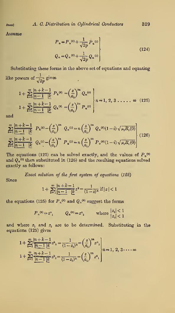
Snow]
Assume
A. C. Distribution in Cylindrical Conductors
P =P (0) + —±— p (1)n" V2p
n
329
«--«-w+^5«-w(124)
Substituting these forms in the above set of equations and equating
like powers of —j= gives
CO
1 + 2CO
1 + 2It
n = l, 2, 3 co (125)
and
"+=4 w»-(£f ^»-»(0°p B<»»(i-i)V^(o)oo
2(126)
The equations (125) can be solved exactly, and the values of Pn(0)
and <2n(0) then substituted in (126) and the resulting equations solved
exactly as follows:
Since
Exact solution of the first system of equations {125)
°° In + Jc— 1 , 1
k=l ro-1 \k (l-2) n ifUKl
the equations (125) for Pn(0) and Q n
(0) suggest the forms
P^=Z\ Qn (0) =2D2 where kl<i
kl<i
and where 2Xand s2 are to be determined. Substituting in the
equations (125) gives
o= \n+ Tc — 1, i /s\2n
J=l n-\ \lc1 (l-^)" \a
2/2
^|W-1 1 -^'W^gl>-l|)T g' (l-z
2 )n \aj Z
\
n=l, 2, 3- • • • oo

330 Scientific Papers of the Bureau of Standards [ Vol. 20
which shows that the 2oo equations will all be satisfied if zxand z2
can be found each numerically less than 1, satisfying the two equa-
tions
(f)H(?)]-
(?)[-*®H(127)
By reference to the equations (120) which determine btand b2 it is
evident that
Si=-J-i and1s
a2b2
where bxand b2 are roots of the corresponding quadratic equations.
In order that zxand z2
shall be less than 1, 6 tand b2 must both be
less than 1, or both greater than 1. Since the product of the two
roots of each equation is 1, it follows that there are two solutions for
the above system of equations (125) given by
or
n w(128)
It will appear presently that the set corresponding to btand 6,
both less than unity leads to positive expressions for the resistance
and inductance, while the other set lead to the same numerical
values, but a negative sign. Using these values of P n(0) and Q n
(0)
in (126) leads to the following equations for the P n(1) and Q n
(1)
Exact solution of the second system of equations {126)
To find PnW and Q n
W as solutions of
°° \n-\-Tc
£1 \n
Assume
(129)
Pn(" = anznl
and Q n(1) = /3ft2
n2 where
22|<1
and substitute in above equations (129).
oo [n + lc — 1
This gives
i-c^r«*.-(t')"a-«-fi5OT'

snow] A. C. Distribution in Cylindrical Conductors
Or, since by the binominal theorem
331
co\
n + Tc — 1
S|w |fc-l;
k-l_.(l-2x) n+1
^-<tHt)" (i-*™*l-«2 (1
If these equations are to hold for every positive integral value of n,
this requires that a and /3 have certain values, and that
a2Z>2 _
2? — m1-0,
MY2,=^-v =
1-2,
(130)
where zu z2 , btand &2 must be the same as in the preceding case.
Since
aj>ib2 andq2&A
\-z2 at1-Zi a2
the constants a and /3 must be so chosen as to satisfy
— axa + afijbji = (1 — i) a
x Vmi-^i (0)|
aj>xl2a -a2P=(l-i) a2VVA (0) J
which being solved, give
(1— £)a
ia= ~
(i _ 52^) fa V^i(0) + \ha2 ^fji2R2 (0)]
(1— i)a20= ~ (l-&2i6
22)[^MlVMACO) +O.VMA (0)]
(131)
(132)
Introducing the results of the first and second stages of the approxi-
mation, namely,
e.-«.» +-^«.m -(*A)-(. +$)(133)

332 Scientific Papers of the Bureau of Standards ivoi.so
into the equation (118) for R and L leads to two infinite series which
are summable. For
fe ax an & a
t5ji\s/ ^J2p £5. \ * /
:W ^ "--#!
Similarly
and
log£-S&-log-^---2-SM
Substituting in (118) gives
+(1-l4l% la,
*&® +l *&&> ^
+ bj>2 (VmA(6) + VmA(6T)]]
But to the same degree of approximation as used in obtaining Pn
and Qn ; that is, neglecting - compared t© —p=
MiJofci) _ ^Mi _ (1 — i) //figi(0)
a^/'oCXi) ^ 2 V 2pand
M2/ (a;2) (1-i) /m2^2 (0)
V^x2J'(x
2)2 \ 2p
Using these expressions in the preceding equation (134) gives,
upon equating reals and imaginaries,
g °2(l-Ws) [(
1 + 2iA| +^'.)V^A(0)+(l+2M,^
+
w
)vraos]^ (i+i)^ if{-:--
1 R e'C.RL-21°eW+j-r+i <138 >

snow] A. G. Distribution in Cylindrical Conductors
The attenuation b and phase velocity V are given by
y=b + i^ = ^(R + ipL))(G + ipG
2&3 = VCR2 + P2i2
) (G* + p2C2) + (RG-fLQ
2 1^= tJ(R2 + p2L2
) (CP + ptC2) - (RG-p'LC)
333
or
(137)
The ratio —W, that is,v
-? is generally negligible, so that (137)
reduces to
F= RCVTD (138)
The positive quantity b t b2 which appears in these formulas maybe found as the root of the quadratic equation
<^KS-^^> &'+ 1 =° (139)
which is less than 1. The other root, being the reciprocal of this,
will be greater than 1, and if used in these formulas would give
the same numerical value of R and L, but both negative in sign.
Special Case.—The circles have equal radii, b2= b
x
R Vm^^o) + VmA (o)
y-2p
m5
6, pwhere b
tis that root of
b2t-
(—
Jb t + 1 = which is less than 1
(140)
(141)
(142)
or
61~i VW "
The asymptotic expressions for alternating current resistance and
inductance of two cylinders here given are believed to be new. Theyhave proven useful in the radio section of this bureau for investi-
gating the precision of measurements of short waves on wires, corre-
sponding to a frequency of (10)7 cycles per second. 8
(&) Special Case. Circular Cylinder Parallel to Semi-
infinite Plane of Finite Conductivity.—If we plaoe s = d+ a2
and holding d fixed let a2 become infinite, this approaches the case
•A. Hund, B. S. Sci. Paper No. 491
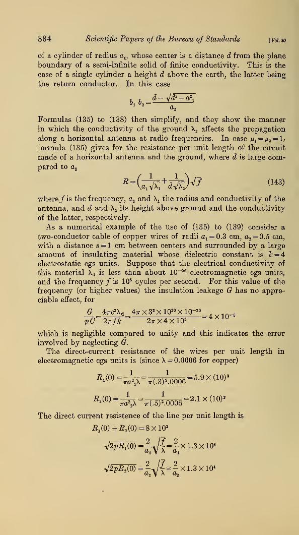
R
334 Scientific Papers of the Bureau of Standards [Voi.to
of a cylinder of radius av whose center is a distance d from the plane
boundary of a semi-infinite solid of finite conductivity. This is the
case of a single cylinder a height d above the earth, the latter being
the return conductor. In this case
i t. d— Jd2 — a2,
&1&2 =a
t
Formulas (135) to (138) then simplify, and they show the mannerin which the conductivity of the ground X2 affects the propagation
along a horizontal antenna at radio frequencies. In case M1= /i2
= l>
formula (135) gives for the resistance per unit length of the circuit
made of a horizontal antenna and the ground, where d is large com-
pared to ax
-fck+57x;)V7 (143>
where/ is the frequency, a1and \ the radius and conductivity of the
antenna, and d and X2 its height above ground and the conductivity
of the latter, respectively.
As a numerical example of the use of (135) to (139) consider a
two-conductor cable of copper wires of radii a 1= 0.3 cm, a2
= 0.5 cm,
with a distance s = 1 cm between centers and surrounded by a large
amount of insulating material whose dielectric constant is Jc=4
electrostatic cgs units. Suppose that the electrical conductivity of
this material Xd is less than about 10-20 electromagnetic cgs units,
and the frequency /is 105 cycles per second. For this value of the
frequency (or higher values) the insulation leakage G has no appre-
ciable effect, for
47rc2Xd 47rX3 2 Xl020 XlQ-20
pC~2irfJc~ 2ttX4x1054 X 1U
which is negligible compared to unity and this indicates the error
involved by neglecting G.
The direct-current resistance of the wires per unit length in
electromagnetic cgs units is (since X = 0.0006 for copper)
The direct current resistence of the line per unit length is
£1(0)+£a(0)--8XlOa
=-Xl.3xl04
V2PS0)-|^/{-|xl.3X10"

snow] A. C. Distribution in Cylindrical Conductors 335
The equation (135) for the alternating current resistance of the line
per unit length is
(electromagnetic cgs units)
The numerical value of & x&2is found as that root of the quadratic
equation (139)
(W 2- 1
~/x75'52
(w +1=-°
which is less than 1. The two roots are &26 1 = .24 or 4.16. Theformer value must be used, and it gives
R = 6.93 (^)x 104 = 113 X 103/1.24X iA .
(^6-) Xl°
as the alternating current resistance of the line per unit length in
electromagnetic cgs units. This is 14 times the direct current
resistance. After R has been computed, the alternating current
inductances L of the line per unit length may be computed by (136).
L= 2loge -^+2°^
Q5=2.85 + .18 = 3.03
(electromagnetic cgs units per cm)
The capacity of the line per unit length is given by (119)
4<7=
32 X1020 X2.85=L56X10 21
(electromagnetic cgs units)
The phase velocity V is next found by means of (138)
F==VIC'
=V3.03X1.56X10-
21= L45 X 1Q1°
which is about half the velocity of light in space. However, the
velocity of light in the medium which is assumed to have a dielectric
capacity fc = 4 is
7 =4f= -T= X1010 = 1.50X10¹⁰
V« V4
which shows that V is very nearly V . In this problem the dielectric
whose specific inductive capacity is 4 electrostatic cgs units is as-
sumed to fill the space external to the wires.

336 Scientific Papers oj'the Bureau of Standards \voi.to
Finally the attenuation constant b is found by (137)
, RGV 113 X103 X 1.56 X10-21 X 1.45 X 1010
100v, in_e= n ~~~R
= l.^O X 1U
The current / is of the form
/= I e-bz cos 2ir/ ft - y\
and the wave length is
V 1.45 X 10¹⁰, . __ ,
-2? = rjFjs= 1,450 meters
VIII. SUMMARY
In a single type of wave the field components are proportional to
eipt-7z where the propagation constant y is b+~£' the real constants
b and V being the attenuation and phase velocity, respectively. Theyare functions of the frequency. There are N— 1 possible values of y
2
and 2N—2 values of y or types of waves for a system of N cylindrical
conductors. The electromagnetic field is, in general, the superposition
of the fields corresponding to each type and these are derivable from
a complex scalar potential 4>, and a vector potential A. On account
of the vast difference in the order of magnitude of the electrical con-
ductivities of a conductor and of a dielectric, certain approximations
can be made in general which are valid from the lowest to the highest
or radio frequencies. These lead to the conclusion that the x — and
y— components of the vector potential are negligible.
Beginning with the differential equations and boundary con-
ditions which 4> and A must satisfy, the existence of a solution 4>
has been proven, and an integral representation of it obtained and
its properties studied by constructing a symmetrical auxiliary function
of two points G(xy^ri), which may be regarded as a generalization
of Green's function. By its means the unknown charges on the
boundaries between different dielectrics are eliminated from con-
sideration and<f>
is determined at all points in terms of its values on
the conducting sections. Certain constants (?nk and Cnk are derived
which in general are complex functions of the frequency, and are
coefficients of leakage and capacity, respectively. The conservation
of electricity for each conductor takes the form, for n = 1, 2, 3 * • • • N.
A'[6r
nk = "kn7^n = 2(£nk + ^Cnk)ck where]^ \Cnk=Ckn
andN NS"nk =S Cnk =
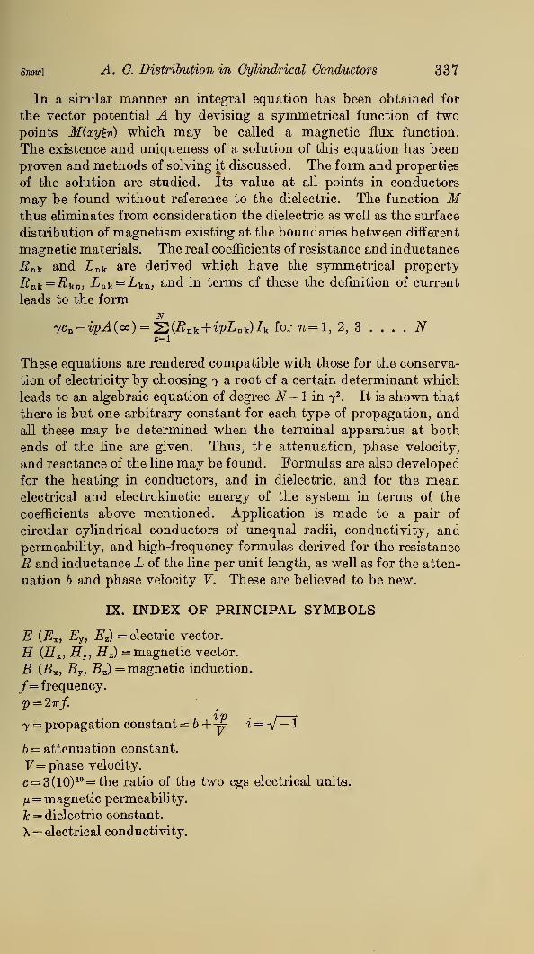
snow] A. C. Distribution in Cylindrical Conductors 337
In a similar manner an integral equation has been obtained for
the vector potential A by devising a symmetrical function of two
points M{xy%i\) which may be called a magnetic flux function.
The existence and uniqueness of a solution of this equation has been
proven and methods of solving it discussed. The form and properties
of the solution are studied. Its value at all points in conductors
may be found without reference to the dielectric. The function Mthus eliminates from consideration the dielectric as well as the surface
distribution of magnetism existing at the boundaries between different
magnetic materials. The real coefficients of resistance and inductance
i?nk and i n k are derived which have the symmetrical property
Rnk = Rkn, ink = ikn, and in terms of these the definition of current
leads to the formN
yc n -ipA(co)=^(Rnk +ipLDb)Ik for n=l, 2, 3 . . . . N
These equations are rendered compatible with those for the conserva-
tion of electricity by choosing y a root of a certain determinant which
leads to an algebraic equation of degree N— 1 in y2
. It is shown that
there is but one arbitrary constant for each type of propagation, and
all these may be determined when the terminal apparatus at both
ends of the line are given. Thus, the attenuation, phase velocity,
and reactance of the line may be found. Formulas are also developed
for the heating in conductors, and in dielectric, and for the meanelectrical and electrokinetic energy of the system in terms of the
coefficients above mentioned. Application is made to a pair of
circular cylindrical conductors of unequal radii, conductivity, andpermeability, and high-frequency formulas derived for the resistance
R and inductance L of the line per unit length, as well as for the atten-
uation b and phase velocity V. These are believed to be new.
IX. INDEX OF PRINCIPAL SYMBOLS
E {E^, Ey , Ez) = electric vector.
E (flx, fly, Hz) = magnetic vector.
B CBX , B7 , Bz) = magnetic induction.
/= frequency.
7 = propagation constant=&+p i=-y — 1
b = attenuation constant.
F= phase velocity.
c = 3(10)10 = the ratio of the two cgs electrical units.
H = magnetic permeability.
Tc = dielectric constant.
X= electrical conductivity.

338 Scientific Papers of the Bureau of Standards ivoi.so
All constants and vectors measured in cgs electromagnetic units
except fc which is measured in electrostatic cgs units so that
Tc— 1 to 5 for most dielectrics.
H= 1 for nonmagnetic metals.
<f>= complex scalar potential. »
A (Ax , A7 , Az ,) = complex vector potential.
Note.—Since A z is the principal component considered Az is
written as A where this can be done without misunderstanding.
Similarly, E is used for Ez where the meaning is plain.
cv c2,' • • • c r = complex constant values of <£ upon conducting sections
Nos. 1, 2, 3, • • • • N.
aj=\$ + f\= complex conductivity of;th material.
dsj = element of arc of natural boundary of section Sj of homogeneousmaterial (conductor or dielectric).
7ij = normal to this boundary curve, see Figure 1.
Qn = complex free charge per unit length upon n th conducting group.
Ga = leakage current (complex) from n th conducting group per unit
length,
(xnk and Cnk = real coefficients of leakage and capacity, respectively,
defined by (26).
7n = z — component of total conduction current through the section
Sn of the 7ith conducting group.
G(xy^rf) = a generalized Green's function 1 defined where intro-
M(xy£ii) = a magnetic flux function J duced.
jffnk and Lnk = coefficients of resistance and inductance; defined by(81).
R and L = the alternating current resistance and inductance per unit
length, respectively, for a simple return circuit of two conductors.
(Equations (135) and (136).)
Washington, January 15, 1925.