altera event-driven datapath processing design handbook · 2020-06-06 · in more complex systems,...
TRANSCRIPT
101 Innovation DriveSan Jose, CA 95134www.altera.com
HB-01002-1.1
Design Handbook
Altera Event-Driven Datapath Processing
Subscribe
Altera Event-Driven Datapath Processing Design Handbook

Altera Event-Driven Datapath Processing Design Handbook May 2011 Altera Corporation
© 2011 Altera Corporation. All rights reserved. ALTERA, ARRIA, CYCLONE, HARDCOPY, MAX, MEGACORE, NIOS, QUARTUS and STRATIX are Reg. U.S. Pat.& Tm. Off. and/or trademarks of Altera Corporation in the U.S. and other countries. All other trademarks and service marks are the property of their respectiveholders as described at www.altera.com/common/legal.html. Altera warrants performance of its semiconductor products to current specifications in accordancewith Altera’s standard warranty, but reserves the right to make changes to any products and services at any time without notice. Altera assumes no responsibility orliability arising out of the application or use of any information, product, or service described herein except as expressly agreed to in writing by Altera. Alteracustomers are advised to obtain the latest version of device specifications before relying on any published information and before placing orders for products orservices.

May 2011 Altera Corporation
Contents
Chapter 1. Introduction to Altera Event-Driven Datapath ProcessingDesign Flow Concepts . . . . . . . . . . . . . . . . . . . . . . . . . . . . . . . . . . . . . . . . . . . . . . . . . . . . . . . . . . . . . . . . . . . 1–1
Efficient Flow . . . . . . . . . . . . . . . . . . . . . . . . . . . . . . . . . . . . . . . . . . . . . . . . . . . . . . . . . . . . . . . . . . . . . . . . 1–2Flexible Flow . . . . . . . . . . . . . . . . . . . . . . . . . . . . . . . . . . . . . . . . . . . . . . . . . . . . . . . . . . . . . . . . . . . . . . . . . 1–3Efficient and Flexible Flow . . . . . . . . . . . . . . . . . . . . . . . . . . . . . . . . . . . . . . . . . . . . . . . . . . . . . . . . . . . . . 1–4
Processing Elements in the Efficient and Flexible Flow . . . . . . . . . . . . . . . . . . . . . . . . . . . . . . . . . . . 1–5Event-Driven Methodology . . . . . . . . . . . . . . . . . . . . . . . . . . . . . . . . . . . . . . . . . . . . . . . . . . . . . . . . . . . . . . . 1–6
Messages, Tasks, and Contexts . . . . . . . . . . . . . . . . . . . . . . . . . . . . . . . . . . . . . . . . . . . . . . . . . . . . . . . . . . 1–6Object-Oriented Programming Analogy . . . . . . . . . . . . . . . . . . . . . . . . . . . . . . . . . . . . . . . . . . . . . . . . . . 1–8
Architecting an Event-Driven System . . . . . . . . . . . . . . . . . . . . . . . . . . . . . . . . . . . . . . . . . . . . . . . . . . . . . . 1–8Design Partitioning . . . . . . . . . . . . . . . . . . . . . . . . . . . . . . . . . . . . . . . . . . . . . . . . . . . . . . . . . . . . . . . . . . . 1–9Context Management . . . . . . . . . . . . . . . . . . . . . . . . . . . . . . . . . . . . . . . . . . . . . . . . . . . . . . . . . . . . . . . . . 1–11
Context Data . . . . . . . . . . . . . . . . . . . . . . . . . . . . . . . . . . . . . . . . . . . . . . . . . . . . . . . . . . . . . . . . . . . . . . 1–12Message Format . . . . . . . . . . . . . . . . . . . . . . . . . . . . . . . . . . . . . . . . . . . . . . . . . . . . . . . . . . . . . . . . . . . . . 1–13Message Interconnect . . . . . . . . . . . . . . . . . . . . . . . . . . . . . . . . . . . . . . . . . . . . . . . . . . . . . . . . . . . . . . . . . 1–13Flow Control PEs . . . . . . . . . . . . . . . . . . . . . . . . . . . . . . . . . . . . . . . . . . . . . . . . . . . . . . . . . . . . . . . . . . . . 1–14
Centralized Message Flow . . . . . . . . . . . . . . . . . . . . . . . . . . . . . . . . . . . . . . . . . . . . . . . . . . . . . . . . . . 1–14Centralized Message Scheduling . . . . . . . . . . . . . . . . . . . . . . . . . . . . . . . . . . . . . . . . . . . . . . . . . . . . . 1–15Unidirectional Message Flow . . . . . . . . . . . . . . . . . . . . . . . . . . . . . . . . . . . . . . . . . . . . . . . . . . . . . . . . 1–15Other Flows . . . . . . . . . . . . . . . . . . . . . . . . . . . . . . . . . . . . . . . . . . . . . . . . . . . . . . . . . . . . . . . . . . . . . . 1–16
Message Buffering . . . . . . . . . . . . . . . . . . . . . . . . . . . . . . . . . . . . . . . . . . . . . . . . . . . . . . . . . . . . . . . . . . . 1–16Ordering . . . . . . . . . . . . . . . . . . . . . . . . . . . . . . . . . . . . . . . . . . . . . . . . . . . . . . . . . . . . . . . . . . . . . . . . . . . . 1–16Scaling . . . . . . . . . . . . . . . . . . . . . . . . . . . . . . . . . . . . . . . . . . . . . . . . . . . . . . . . . . . . . . . . . . . . . . . . . . . . . 1–17
Duplicating PEs . . . . . . . . . . . . . . . . . . . . . . . . . . . . . . . . . . . . . . . . . . . . . . . . . . . . . . . . . . . . . . . . . . . 1–17Duplicating Systems . . . . . . . . . . . . . . . . . . . . . . . . . . . . . . . . . . . . . . . . . . . . . . . . . . . . . . . . . . . . . . . 1–18
Chapter 2. Message FormatAvalon-ST PE Message Interface Specification . . . . . . . . . . . . . . . . . . . . . . . . . . . . . . . . . . . . . . . . . . . . . . . 2–1
Interface Signals . . . . . . . . . . . . . . . . . . . . . . . . . . . . . . . . . . . . . . . . . . . . . . . . . . . . . . . . . . . . . . . . . . . . . . 2–2Ready Latency . . . . . . . . . . . . . . . . . . . . . . . . . . . . . . . . . . . . . . . . . . . . . . . . . . . . . . . . . . . . . . . . . . . . . . . . 2–2Packet Data Transfer Messages . . . . . . . . . . . . . . . . . . . . . . . . . . . . . . . . . . . . . . . . . . . . . . . . . . . . . . . . . 2–2Avalon-ST PE Message Format . . . . . . . . . . . . . . . . . . . . . . . . . . . . . . . . . . . . . . . . . . . . . . . . . . . . . . . . . 2–3
Control Word . . . . . . . . . . . . . . . . . . . . . . . . . . . . . . . . . . . . . . . . . . . . . . . . . . . . . . . . . . . . . . . . . . . . . . 2–3Data Arguments . . . . . . . . . . . . . . . . . . . . . . . . . . . . . . . . . . . . . . . . . . . . . . . . . . . . . . . . . . . . . . . . . . . . 2–4
Message Transmission . . . . . . . . . . . . . . . . . . . . . . . . . . . . . . . . . . . . . . . . . . . . . . . . . . . . . . . . . . . . . . . . . . . 2–4The altera_pe_message_format Tcl Package Specification . . . . . . . . . . . . . . . . . . . . . . . . . . . . . . . . . . . . . 2–7
Tcl Command Reference . . . . . . . . . . . . . . . . . . . . . . . . . . . . . . . . . . . . . . . . . . . . . . . . . . . . . . . . . . . . . . . 2–7set_message_property . . . . . . . . . . . . . . . . . . . . . . . . . . . . . . . . . . . . . . . . . . . . . . . . . . . . . . . . . . . . . . . 2–8get_message_property . . . . . . . . . . . . . . . . . . . . . . . . . . . . . . . . . . . . . . . . . . . . . . . . . . . . . . . . . . . . . . 2–8set_message_subfield_property . . . . . . . . . . . . . . . . . . . . . . . . . . . . . . . . . . . . . . . . . . . . . . . . . . . . . . 2–9get_message_subfield_property . . . . . . . . . . . . . . . . . . . . . . . . . . . . . . . . . . . . . . . . . . . . . . . . . . . . . . 2–9set_message_subfield_hdl_port . . . . . . . . . . . . . . . . . . . . . . . . . . . . . . . . . . . . . . . . . . . . . . . . . . . . . . 2–10validate_and_create . . . . . . . . . . . . . . . . . . . . . . . . . . . . . . . . . . . . . . . . . . . . . . . . . . . . . . . . . . . . . . . . 2–10
Validation of Message Interfaces . . . . . . . . . . . . . . . . . . . . . . . . . . . . . . . . . . . . . . . . . . . . . . . . . . . . . . . 2–11Binding HDL ports to the Data Port . . . . . . . . . . . . . . . . . . . . . . . . . . . . . . . . . . . . . . . . . . . . . . . . . . . . 2–11
Message Sources . . . . . . . . . . . . . . . . . . . . . . . . . . . . . . . . . . . . . . . . . . . . . . . . . . . . . . . . . . . . . . . . . . 2–11Message Sinks . . . . . . . . . . . . . . . . . . . . . . . . . . . . . . . . . . . . . . . . . . . . . . . . . . . . . . . . . . . . . . . . . . . . . 2–15
Altera Event-Driven Datapath Processing Design Handbook

iv Contents
Chapter 3. Message InterconnectInterconnect Approaches . . . . . . . . . . . . . . . . . . . . . . . . . . . . . . . . . . . . . . . . . . . . . . . . . . . . . . . . . . . . . . . . . 3–1
Fully-Connected System with a Single Message Interconnect . . . . . . . . . . . . . . . . . . . . . . . . . . . . . 3–1Required Connections with Multiple Switches . . . . . . . . . . . . . . . . . . . . . . . . . . . . . . . . . . . . . . . . . . 3–2Fully-Connected System with Multiple Interconnects . . . . . . . . . . . . . . . . . . . . . . . . . . . . . . . . . . . . 3–3
Processing Element Message Switch . . . . . . . . . . . . . . . . . . . . . . . . . . . . . . . . . . . . . . . . . . . . . . . . . . . . . . . 3–3Parameters . . . . . . . . . . . . . . . . . . . . . . . . . . . . . . . . . . . . . . . . . . . . . . . . . . . . . . . . . . . . . . . . . . . . . . . . . . . 3–4
Interface Ports and Signals . . . . . . . . . . . . . . . . . . . . . . . . . . . . . . . . . . . . . . . . . . . . . . . . . . . . . . . . . . . . . . . . 3–7Design Considerations . . . . . . . . . . . . . . . . . . . . . . . . . . . . . . . . . . . . . . . . . . . . . . . . . . . . . . . . . . . . . . . . . 3–7
Backpressure . . . . . . . . . . . . . . . . . . . . . . . . . . . . . . . . . . . . . . . . . . . . . . . . . . . . . . . . . . . . . . . . . . . . . . . 3–8Unmatched Routing Field . . . . . . . . . . . . . . . . . . . . . . . . . . . . . . . . . . . . . . . . . . . . . . . . . . . . . . . . . . . 3–8Multiple Message Interconnects in a System . . . . . . . . . . . . . . . . . . . . . . . . . . . . . . . . . . . . . . . . . . . . 3–8Partial-Crossbar Switches . . . . . . . . . . . . . . . . . . . . . . . . . . . . . . . . . . . . . . . . . . . . . . . . . . . . . . . . . . . . 3–8Multicast Routing . . . . . . . . . . . . . . . . . . . . . . . . . . . . . . . . . . . . . . . . . . . . . . . . . . . . . . . . . . . . . . . . . . 3–8
Chapter 4. Processing ElementsDesign Requirements Overview . . . . . . . . . . . . . . . . . . . . . . . . . . . . . . . . . . . . . . . . . . . . . . . . . . . . . . . . . . . 4–2
Processing Element Types by Function . . . . . . . . . . . . . . . . . . . . . . . . . . . . . . . . . . . . . . . . . . . . . . . . . . . 4–3Input PEs . . . . . . . . . . . . . . . . . . . . . . . . . . . . . . . . . . . . . . . . . . . . . . . . . . . . . . . . . . . . . . . . . . . . . . . . . . 4–3Output PEs . . . . . . . . . . . . . . . . . . . . . . . . . . . . . . . . . . . . . . . . . . . . . . . . . . . . . . . . . . . . . . . . . . . . . . . . 4–3Computational PEs . . . . . . . . . . . . . . . . . . . . . . . . . . . . . . . . . . . . . . . . . . . . . . . . . . . . . . . . . . . . . . . . . 4–3Context Management PEs . . . . . . . . . . . . . . . . . . . . . . . . . . . . . . . . . . . . . . . . . . . . . . . . . . . . . . . . . . . 4–4Flow Control PEs . . . . . . . . . . . . . . . . . . . . . . . . . . . . . . . . . . . . . . . . . . . . . . . . . . . . . . . . . . . . . . . . . . . 4–4
Interfaces . . . . . . . . . . . . . . . . . . . . . . . . . . . . . . . . . . . . . . . . . . . . . . . . . . . . . . . . . . . . . . . . . . . . . . . . . . . . . . . 4–4Message Interfaces . . . . . . . . . . . . . . . . . . . . . . . . . . . . . . . . . . . . . . . . . . . . . . . . . . . . . . . . . . . . . . . . . . . . 4–4
Message Clock Interface Signals . . . . . . . . . . . . . . . . . . . . . . . . . . . . . . . . . . . . . . . . . . . . . . . . . . . . . . 4–5Message Interface Signals . . . . . . . . . . . . . . . . . . . . . . . . . . . . . . . . . . . . . . . . . . . . . . . . . . . . . . . . . . . . 4–5
Context Management Interfaces . . . . . . . . . . . . . . . . . . . . . . . . . . . . . . . . . . . . . . . . . . . . . . . . . . . . . . . . . 4–6Context Register Interfaces . . . . . . . . . . . . . . . . . . . . . . . . . . . . . . . . . . . . . . . . . . . . . . . . . . . . . . . . . . . . . 4–6Other User-Defined Interfaces . . . . . . . . . . . . . . . . . . . . . . . . . . . . . . . . . . . . . . . . . . . . . . . . . . . . . . . . . . 4–6
System Considerations . . . . . . . . . . . . . . . . . . . . . . . . . . . . . . . . . . . . . . . . . . . . . . . . . . . . . . . . . . . . . . . . . . . 4–6
Additional InformationDocument Revision History . . . . . . . . . . . . . . . . . . . . . . . . . . . . . . . . . . . . . . . . . . . . . . . . . . . . . . . . . . . Info–1How to Contact Altera . . . . . . . . . . . . . . . . . . . . . . . . . . . . . . . . . . . . . . . . . . . . . . . . . . . . . . . . . . . . . . . . Info–1Typographic Conventions . . . . . . . . . . . . . . . . . . . . . . . . . . . . . . . . . . . . . . . . . . . . . . . . . . . . . . . . . . . . . Info–1
Altera Event-Driven Datapath Processing Design Handbook May 2011 Altera Corporation

May 2011 Altera Corporation
1. Introduction to Altera Event-DrivenDatapath Processing
This document describes the Altera® event-driven datapath processing technology. Using the technology, you can process large amounts of data at line rates, such as Internet traffic and streaming video, with Altera FPGAs. Its modularity is ideal for developing datapath processing solutions.
The technology consists of an event-driven data processing methodology, and hardware and software-programmable building blocks, called processing elements (PE). Each hardware PE and software-programmable PE, built as reusable intellectual property (IP), provides separate, distinct functionality dedicated to perform a particular task. Using an event-driven methodology, multiple blocks of data are scheduled for processing and move through different PEs of the datapath concurrently.
Altera event-driven datapath processing has the following features and benefits:
■ Greatly-improved system performance
■ Parallel processing of multiple sets of data, while maintaining the context of each set of data
■ Hardware PEs for compute-intensive tasks
■ Software-programmable PEs for flexibility
■ Reusable IP
■ Scalable design
■ Flexibility to repartition the system at a late development stage without architectural changes
■ Easy route to migrating processes between hardware and software domains, even late in the design cycle
■ Independent, autonomous design of PEs
■ Software control, scheduling, and classification of high-speed datapaths
f After reading this document, Altera recommends using the Getting Started with the Nios II DPX Datapath Processor Tutorial to familiarize yourself with a working system.
Design Flow ConceptsIn any data processing scenario, data comes in, data gets processed, and data goes out. With Altera event-driven datapath processing, data moves through the system in discrete, pipelined blocks. Each block moves through multiple processing elements. Multiple blocks of data move through different parts of the system concurrently. The processing pipeline can be linear or very dynamic, depending on your hardware design and the sophistication of your flow control.
Processing data at line rates in FPGAs requires maximum efficiency at every point along the datapath. Efficiency is achievable with tradeoffs in the following types of systems:
Altera Event-Driven Datapath Processing Design Handbook

1–2 Chapter 1: Introduction to Altera Event-Driven Datapath ProcessingDesign Flow Concepts
■ Efficient flow—Systems where the data is directly manipulated only by hardware are efficient but not flexible.
■ Flexible flow—Systems where the data is directly manipulated by both hardware and software trade some efficiency for flexibility.
■ Efficient and flexible flow—Systems where the data is manipulated by hardware, but where control decisions, such as scheduling, are made by software based on the data flowing through the system can be both efficient and flexible.
The following sections describe the types of flows in increasing order of complexity and capability.
Efficient FlowThe efficient flow does not take full advantage of the power of the event-driven methodology, but is a good starting point for explanation purposes. This approach is useful for systems where the processing flow is fixed and data visits each PE only once. The simplest flow uses direct, linear connections between PEs. Data moves through the PEs sequentially in a FIFO-style pipeline. Each PE knows where to pass control. Figure 1–1 shows an efficient linear flow.
Advantages of linear processing include the following items:
■ No time or buffer overhead.
■ Direct, predictable path.
■ No flow decisions.
Disadvantages a linear processing include the following items:
■ No flexibility.
■ One PE stalling can stall the whole pipeline.
■ Does not make full use of the power of the event-driven methodology.
Figure 1–1. Efficient Processing Flow
Processing Element
Processing Element
Output Processing
Element
Input Processing
Element
DataIn
DataOut
Altera Event-Driven Datapath Processing Design Handbook May 2011 Altera Corporation

Chapter 1: Introduction to Altera Event-Driven Datapath Processing 1–3Design Flow Concepts
Flexible FlowIn more complex systems, processing does not necessarily take place linearly, and certain processing sometimes happens more than once on the same block of data. Figure 1–2 shows a flexible design where the processing flow can take multiple paths.
Flexible flows require a mechanism to very quickly route the data through the system. Each PE communicates with a centralized mechanism to route the data. Dedicated interconnect circuitry or a state machine handles the routing.
Advantages of a flexible processing flow include the following items:
■ Allows for nonlinear processing.
■ Data can route through PEs more than once.
■ Minimal stalling, slower tasks ahead do not create blockage.
■ You can design PEs for reuse.
Disadvantages of a flexible processing flow include the following items:
■ Nonobvious, nondirect path.
■ Extra buffer space to handle backpressure.
Figure 1–2. Flexible Processing Flow
Mechanism to route flow
InputProcessing
Element
OutputProcessing
Element
DataIn
DataOut
HardwareProcessing
Element
Software-Programmable
ProcessingElement
Software-Programmable
ProcessingElement
Software-Programmable
ProcessingElement
HardwareProcessing
Element
HardwareProcessing
Element
May 2011 Altera Corporation Altera Event-Driven Datapath Processing Design Handbook
1–4 Chapter 1: Introduction to Altera Event-Driven Datapath ProcessingDesign Flow Concepts
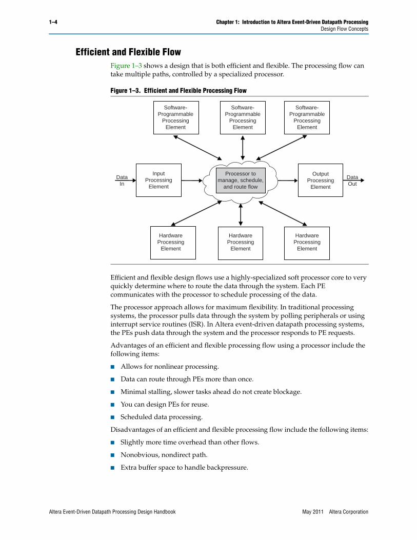
Efficient and Flexible FlowFigure 1–3 shows a design that is both efficient and flexible. The processing flow can take multiple paths, controlled by a specialized processor.
Efficient and flexible design flows use a highly-specialized soft processor core to very quickly determine where to route the data through the system. Each PE communicates with the processor to schedule processing of the data.
The processor approach allows for maximum flexibility. In traditional processing systems, the processor pulls data through the system by polling peripherals or using interrupt service routines (ISR). In Altera event-driven datapath processing systems, the PEs push data through the system and the processor responds to PE requests.
Advantages of an efficient and flexible processing flow using a processor include the following items:
■ Allows for nonlinear processing.
■ Data can route through PEs more than once.
■ Minimal stalling, slower tasks ahead do not create blockage.
■ You can design PEs for reuse.
■ Scheduled data processing.
Disadvantages of an efficient and flexible processing flow include the following items:
■ Slightly more time overhead than other flows.
■ Nonobvious, nondirect path.
■ Extra buffer space to handle backpressure.
Figure 1–3. Efficient and Flexible Processing Flow
Processor tomanage, schedule,
and route flow
HardwareProcessing
Element
Software-Programmable
ProcessingElement
InputProcessing
Element
OutputProcessing
Element
DataIn
DataOut
Software-Programmable
ProcessingElement
Software-Programmable
ProcessingElement
HardwareProcessing
Element
HardwareProcessing
Element
Altera Event-Driven Datapath Processing Design Handbook May 2011 Altera Corporation

Chapter 1: Introduction to Altera Event-Driven Datapath Processing 1–5Design Flow Concepts
Processing Elements in the Efficient and Flexible FlowPopular packet processing architectures, such as network processing units, employ a combination of processors (microcode engines, CPUs, and hyperthread engines) to perform control and packet processing functions while offloading the bulk of the compute-intensive operations to hard macros.
Until now, datapath processing in FPGAs has been primarily attempted in hardware using custom RTL or by reusing standard IP cores. Altera event-driven datapath processing uses a combination of dedicated, optimized processors; multiple cores; custom, accelerated hardware PEs; and tightly-integrated hardware and software to achieve maximum optimization.
The Nios® II DPX datapath processor is a special-purpose processor with minimal operating system overhead optimized for datapath processing.
f For more information, refer to the Nios II DPX Datapath Processor Handbook.
Altera event-driven datapath processing encourages custom solutions with a combination of PEs and software and system development tools. Within this framework, you build custom processing solutions by employing an optimum combination of software-programmable and hardware PEs. You can even customize your existing IP for use in event-driven designs.
Nios II DPX Datapath Processor for Flow Control
The Nios II DPX datapath processor offers a software design flow for control and scheduling of datapaths.
Nios II DPX Datapath Processor for Processing Data
In addition, the Nios II DPX datapath processor handles less time-intensive computations. Software-programmable PEs such as the Nios II DPX datapath processor are useful for packet processing functions such as header parsing and classification.
Hardware PEs for Processing Data
Like typical network processing units, custom hardware handles compute-intensive operations. Hardware PEs are essential for time-critical functions such as lookups and encryption. The following list shows some of the possible uses for PEs:
■ Encryption
■ Cyclic redundancy check (CRC)
■ Deep packet inspection
■ Search and lookup
■ Traffic management
May 2011 Altera Corporation Altera Event-Driven Datapath Processing Design Handbook
1–6 Chapter 1: Introduction to Altera Event-Driven Datapath ProcessingEvent-Driven Methodology
Event-Driven MethodologyAltera event-driven datapath processing uses an event-driven methodology to move information through the system. Event messages sent to and from various parts of the system control the flow of processing. Each PE in the system is capable of sending, receiving, or both sending and receiving information through event messages.
This technique allows the flow of execution for a particular data item (a packet of data for example) to pass from one PE to another. When a PE receives an event message, the PE performs its associated task on the associated data. When finished, the PE sends an event message to forward control on to the next PE in the processing flow.
With event-driven processing, you gain access to a scalable and flexible design methodology, allowing you to update your system easily throughout the design cycle. Event-driven processing allows parallel processing of multiple sets of data, while maintaining the context of the data.
With the processing divided into discrete pieces, event-driven systems function efficiently in pipelined architectures. Each PE provides a distinct separation of processing in the system. This separation allows concurrent processing of multiple sets of data, where the sets reside in different PEs, like a pipeline stage in the system.
Messages, Tasks, and ContextsMessages carry control information, arguments, and sometimes other data between PEs in a system.
Tasks are computational operations performed by hardware and software-programmable PEs. When a PE receives a message, the PE performs the task requested in the message. Hardware tasks are performed in hardware; software tasks are loaded by a processor and executed.
Contexts are application-specific sets of information shared between PEs. A context can be as simple as a few bytes of identifying information to something more complex, such as a reserved set of registers for a processor and a large amount of associated data. For example, in packet processing, a context might include the packet data and intermediate variables that need to be passed from task to task. When a message instructs a PE to perform a task, the context contains the data the task references.
When the context data is minimal, it can be entirely passed in the message. More complex contexts are stored in memory and assigned a context ID (CID), which gets passed in the message. PEs use the CID as a handle to the context when performing tasks.
The following list shows some possible uses for context data:
■ Variables shared by tasks in your program
■ Packet processing packet headers for various levels of the IP stack
■ Whole packets for deep packet inspection
■ Long Term Evolution (LTE) users and symbols in wireless applications
■ Lines and frames in video processing applications
■ Frames and macroblocks in coder/decoder (CODEC) applications
Altera Event-Driven Datapath Processing Design Handbook May 2011 Altera Corporation
Chapter 1: Introduction to Altera Event-Driven Datapath Processing 1–7Event-Driven Methodology
Event-driven processing is typically implemented on multicore and multithreaded hardware, which allows multiple blocks of data to be processed concurrently. By using separate contexts for each block of data, each block is processed independently and switching to process the next block of data happens more efficiently.
1 It is possible to design systems with PEs that work on the same context concurrently. When designing your system, ensure that you process the data in the correct order. One safeguard to maintain context is to only allow one task to work on a context at any given time.
Each PE in the system must have a message interface capable of sending messages, receiving messages, or both, using a common message format. For more information, refer to Chapter 2, Message Format.
PEs in a system are connected together through a message interconnect. The message interconnect is circuitry for passing messages from one PE to other PEs. The message interconnect might be as simple as a set of wires where two PEs are directly connected, or as complex as a sophisticated packet switch network.
Figure 1–1 on page 1–2 shows a system with simple, direct message interconnects between each set of PEs in the pipeline and Figure 1–2 on page 1–3 shows a system with a more complex, central message interconnect. For more information about the message interconnect, refer to Chapter 3, Message Interconnect.
In these distributed computing systems, the overall process is divided into individual tasks and distributed to PEs, which perform the tasks. The flow of processing is controlled by the sending and receiving of messages. A task is not executed until a PE receives a message requesting that task to be performed. Upon receipt, the PE performs the requested task. When the task is complete the PE routes control of the processing back through the message interconnect to another PE. This approach requires that each task has knowledge of where to send a message when the task completes, be it back to a central location for scheduling or directly to another PE.
This event-driven design methodology allows you more flexibility in your designs than traditional methods, and offers the following benefits:
■ Ease of integration—By designing PEs to connect to a common message interconnect using a common message interface, system designers can easily integrate multiple PEs in a system. Adding and removing PEs in the system require adjustments only to the message interconnect.
■ Ease of partitioning hardware and software—The ease of integration also covers partitioning a design between hardware and software. To an event-driven processing system, hardware accelerators and software tasks appear the same. The system does not need to know how the PE performs the task, only which PE performs the task. You can replace a processor with a hardware accelerator, or vice versa, performing the same task without having to redesign the system.
■ IP reuse—By maintaining a common message interface, all PEs are usable in future designs with no modifications. Every time you build a PE, you increase your IP portfolio for future designs.
May 2011 Altera Corporation Altera Event-Driven Datapath Processing Design Handbook

1–8 Chapter 1: Introduction to Altera Event-Driven Datapath ProcessingArchitecting an Event-Driven System
■ Resource sharing and replication—Using a message interconnect, every PE can have access to all the PEs in the system. This method allows a PE to be shared among all the other PEs in the system. If the bandwidth of a PE becomes limiting, the event-driven framework easily allows you to replicate a PE and add it to the system.
■ Pipelined architecture—By dividing the process into tasks, event-driven processing can be pipelined.
Object-Oriented Programming AnalogyAltera event-driven datapath processing is a form of distributed computing. The concepts of centralized versus distributed computing have parallels similar to structured versus object oriented programming.
In object-oriented programming, the data is the main focus, as opposed to structured programming, where the function is the main focus. The object-oriented design describes the flow of data in the system, while a structured design describes the flow of function calls.
Centralized computing is like a main() function which calls a(), then b(), then c(). Function a() does not need to know that b() is called next. main() takes care of the calling order and passes any data returned from a() as input to b().
Distributed-computing software tasks operating on context data are like C++ class member functions operating on the object’s private data members. Passing an event message, which carries a context, is like invoking a class member function, which massages the data defined for that class instance. The task decides where to pass the context via a message for further processing. The CID is like an object’s this pointer. Creation of a context and its registers is like instantiation of an object, where the registers are like object init() member function parameters.
Architecting an Event-Driven SystemEvent-driven systems require proper planning and design to ensure interoperability between PEs in the system. This section covers the following topics:
■ “Design Partitioning” on page 1–9
■ “Context Management” on page 1–11
■ “Message Format” on page 1–13
■ “Message Interconnect” on page 1–13
■ “Flow Control PEs” on page 1–14
■ “Message Buffering” on page 1–16
■ “Ordering” on page 1–16
■ “Scaling” on page 1–17
Altera Event-Driven Datapath Processing Design Handbook May 2011 Altera Corporation

Chapter 1: Introduction to Altera Event-Driven Datapath Processing 1–9Architecting an Event-Driven System
Design PartitioningThe first step in designing your system is to divide the overall process into tasks. Each task should have a clear processing boundary. Use the following guidelines for partitioning your tasks:
■ Hardware and software boundaries—Consider which portions of the process are required to be in hardware or software. For example, hardware tasks are required to provide the interfaces into and out of the system and when the task cannot be performed efficiently in software. Software tasks are desirable for lower performance functions because they allow rapid reconfigurability, software redesign, and easier debugging. Some tasks can be performed in hardware or software allowing you the flexibility to implement the task as you wish.
■ Branch conditions—The point the processing flow branches between two or more processing paths is a good place to separate tasks. Processing flow can jump over portions of the process which are not needed for that particular set of data.
■ Execution time—Avoid PEs with long execution times to minimize stalling.
Consider the example packet processing system in Figure 1–4. Tasks are performed in both hardware and software. The mechanism to manage, schedule, and route processing flow is the combination of message interconnect components and a Nios II DPX datapath processor.
f For information about the Nios II DPX datapath processor, refer to the Nios II DPX Datapath Processor Handbook.
Figure 1–4. Example Packet Processing System
Processing Element(Nios II DPX Datapath Processor)
ProcessingElement
(Lookup Task)
ProcessingElement
(Input Task)
ProcessingElement
(Output Task)
(decisions)
Mechanism tomanage, schedule,
and route flow
(pathway)
ParseTask
ProcessTask
FilterTask
May 2011 Altera Corporation Altera Event-Driven Datapath Processing Design Handbook
1–10 Chapter 1: Introduction to Altera Event-Driven Datapath ProcessingArchitecting an Event-Driven System
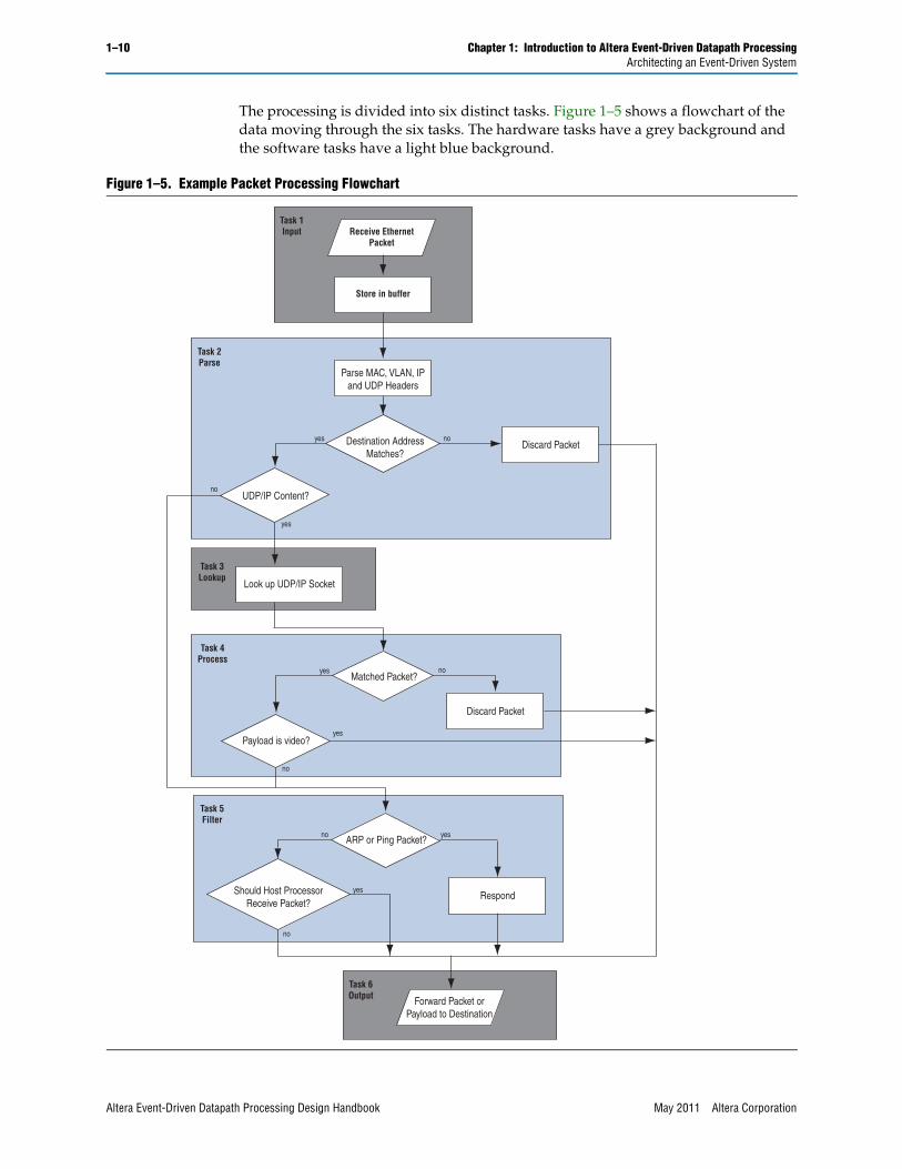
The processing is divided into six distinct tasks. Figure 1–5 shows a flowchart of the data moving through the six tasks. The hardware tasks have a grey background and the software tasks have a light blue background.
Figure 1–5. Example Packet Processing Flowchart
Discard Packet
Payload is video?yes
no
ARP or Ping Packet?no yes
RespondShould Host ProcessorReceive Packet?
yes
Task 5Filter
no
UDP/IP Content?no
yes
Task 3Lookup
Look up UDP/IP Socket
Matched Packet?yes no
Task 4Process
Task 6Output Forward Packet or
Payload to Destination
Task 1Input Receive Ethernet
Packet
Store in buffer
Parse MAC, VLAN, IPand UDP Headers
Destination AddressMatches?
yes noDiscard Packet
Task 2Parse
Altera Event-Driven Datapath Processing Design Handbook May 2011 Altera Corporation

Chapter 1: Introduction to Altera Event-Driven Datapath Processing 1–11Architecting an Event-Driven System
The system receives Ethernet traffic, extracts video data from certain packets and forwards the data on for further processing. The video data consists of MPEG-2 transport stream packets, which when received, are encapsulated inside UDP/IP for transmission via Ethernet. The video data that is forwarded for further processing consists of the raw MPEG-2 transport stream information. Nonvideo data is filtered and either discarded, responded to, or forwarded to a host processor for further processing.
The input and output tasks need to be implemented in hardware because they provide the external interface to the system. The lookup task is better implemented in hardware because a software task cannot perform a destination MAC lookup as efficiently as a hardware-based content-addressable memory lookup table. The parse, process, and filter tasks are targeted for software running on processor such as the Nios II DPX datapath processor.
The parse task, implemented in software, falls between the input and lookup hardware tasks, and makes decisions to bypass tasks when appropriate. Process and filter are broken up into two software tasks, providing an entry point into the filter task from the parse task, and allowing the process task to bypass the filter task when appropriate. The benefit of event-driven processing is that these boundaries are flexible, allowing you to break up a task, move a task from software to hardware (or vice versa), and add additional tasks to the system without needing to redesign the other PEs in the system.
Context ManagementThe pipelined architecture of Altera event-driven systems allows the system to process multiple contexts concurrently. Because each context is processed independently, the integrity of each context must be maintained and not corrupted by other activity in the system.
In cases where the entire context is passed in the message, integrity is inherently maintained. When a PE receives a message, the PE runs tasks that read the data, perform processing, package the context in a new message, and send the message down the line. Because the message routes only to its intended destination, the context cannot be corrupted by other activity in the system.
In cases where the context is being stored rather than passed, a CID is assigned to the context for tracking purposes. PEs use the CID to identify the context to process.
1 For systems where the complete context of the data can be passed via messages, the use of a CID is optional.
The CID is usually passed to the PEs in messages and identifies the set of data a PE works on. As the flow of processing moves from task to task, the CID is passed along in the message requesting the next task, giving the task knowledge of which set of data to work on.
When a PE receives a message requesting a task with an associated CID, the control of processing for that set of data is transferred to that task. In most cases, to maintain the integrity of the data, no other task should access or perform any processing on that set of data. When the task is complete, it transfers the ownership and control of processing to the next task by message.
May 2011 Altera Corporation Altera Event-Driven Datapath Processing Design Handbook

1–12 Chapter 1: Introduction to Altera Event-Driven Datapath ProcessingArchitecting an Event-Driven System
The CID can also assist in maintaining order of the processing in your system. By assigning CIDs in sequential order as data comes into the system, the processor can use the CID to maintain the order of data leaving the system. For more information about ordering, refer to “Ordering” on page 1–16.
Context Data Different tasks often need different data. For example, Table 1–1 shows the data required by each task in the system in Figure 1–4 on page 1–9.
The following sections describe ways to hold and access the data in your system.
PE Messages
The “Avalon-ST PE Message Interface Specification” on page 2–1 allows data arguments to be passed in the messages sent between PEs and their associated tasks. The number of data arguments allowed is determined by the PEs sending and receiving the message. The data being transferred is specific to the task. The data can be arguments for the task, control information, or a combination of both.
For example, in the system shown in Figure 1–4 on page 1–9, messages sent to the lookup task contain the IP address and UDP socket. The lookup task uses the data to find the destination MAC, which it then forwards in a message to the process task. The output task receives control information in a message telling the task to either discard or forward the packet.
Memory
Like most embedded systems, data can also be stored in memory and accessed directly by PEs. The memory can either be on-chip or an external memory device. Only PEs that need access to a memory need to interface to it. For the system in Figure 1–4 on page 1–9, the input task writes the incoming packets to a memory buffer. The output task reads the buffer and retrieves the packets before updating and forwarding. The lookup PE has access to a separate RAM for the hardware-based content-addressable memory lookup table.
Registers
For systems designed with register sets for each context, context data can be stored in those registers, removing the need to pass the data through messages or retrieve through memory accesses. This technique provides maximum efficiency and is especially useful for PEs that perform multiple tasks in succession on a single context. The storage persists for the life of the context.
Table 1–1. Example Task Data
Task Data
Input Header and packet
Parse Header (MAC, VLAN, IP, UDP, destination address)
Lookup IP address and UDP socket
Process Destination MAC and header
Filter Header (packet type)
Output Updated header and packet
Altera Event-Driven Datapath Processing Design Handbook May 2011 Altera Corporation

Chapter 1: Introduction to Altera Event-Driven Datapath Processing 1–13Architecting an Event-Driven System
f For more information about the Nios II DPX datapath processor context registers, refer to the Nios II DPX Datapath Processor Handbook.
Message FormatA single message format usable by all the PEs in your system is key to the flexibility and scalability of your system. The “Avalon-ST PE Message Interface Specification” on page 2–1 defines the message format.
The Avalon Streaming (Avalon-ST) PE message format consists of a control word and data arguments. The fields in the control word are configurable, but must be the same for all PEs connected together in your system. For a list of available fields for the control word, refer to “Control Word” on page 2–3.
When defining the control word for your system, you specify which control fields to include, each control field's bit width, and the position of each control field inside the control word. Providing these properties as configuration options on your PEs allows the control word to be adjusted as the needs of the system change.
Each PE within the system is required to have a unique processing element ID (PEID). PE messages include the PEID in the message format of outgoing messages, providing routing information to the message interconnect. Each PE you design must know the PEIDs of the PEs it sends messages to, to correctly route messages.
For systems containing PEs that perform more than one task, the message format must also include a task ID to differentiate between tasks in a PE. Task IDs must be unique within PEs, but not across PEs. Each PE you design must know the task IDs of the tasks in the PEs it sends messages to, to correctly route messages.
The task ID, passed as part of message format in outgoing messages, tells the receiving PE which task to perform. PEs that perform only one task can ignore the task ID on the receipt of a message.
For data arguments, define a standard ordering of the arguments so that sending and receiving PEs correctly pass the arguments. The number of data arguments in a message can vary, depending on the message being sent. The only requirement is that at least one data argument is passed per message.
Refer to Chapter 2, Message Format for a detailed explanation of all message format topics.
Message InterconnectMessages travel to and from PEs in the system through the message interconnect. In Altera event-driven datapath processing systems, interfaces between the message interconnect and the PEs must follow the “Avalon-ST PE Message Interface Specification” on page 2–1.
The simplest message interconnect is direct connections between PEs message transmit (TX) ports and receive (RX) ports. In typical systems, the message interconnect has intelligence built in to route the messages between PEs. Typically, the message interconnect allows each PE to send messages to any PE in the system, including itself. A PE sending messages to itself is useful when a PE can do multiple tasks, such as a software programmable PE, or when the processing flow can take multiple paths.
May 2011 Altera Corporation Altera Event-Driven Datapath Processing Design Handbook

1–14 Chapter 1: Introduction to Altera Event-Driven Datapath ProcessingArchitecting an Event-Driven System
1 Altera’s Processing Element Message Switch component provides a full crossbar message interconnect switch that is customizable, allowing you to specify the number input and output ports, as well as the location and size of the destination field. For more information, refer to “Processing Element Message Switch” on page 3–3.
When FPGA space is at a premium or you simply want to reduce complexity, you might choose to optimize the message interconnect in your system. Using a partial crossbar or multiple message interconnect switches, you can reduce your message interconnect to the minimum possible number of connections between PEs.
For example, in the system shown in Figure 1–3 on page 1–4, a Nios II DPX datapath processor is used as a central task scheduler. Each PE sends messages only to the processor PE and receives messages only from the processor PE. To initiate software tasks, the processor PE sends messages through the message interconnect to itself. One message interconnect switch going into the processor PE and one switch coming out is all that is needed to correctly connect all the PEs.
For systems with large numbers of PEs, join multiple message interconnects together. This technique can decrease the overall size of the message interconnect and still allow message passing between all PEs.
Refer to Chapter 3, Message Interconnect for a detailed explanation and message interconnect examples.
Flow Control PEsFor flexible systems, creating and designating a control PE or scheduling PE for flow management provides a centralized point for the system management. There are many ways to structure your system using a PE for flow control, and the common element in each is controlling how messages move through the system.
Flow control PEs offer the following benefits:
■ Removes the need for each PE to have detailed knowledge of the entire system or operation.
■ Allows for quick system redesign without the need for redefining the hardware.
The following sections describe some example uses of flow control PEs.
Centralized Message FlowThe system shown in Figure 1–3 on page 1–4 uses a centralized message flow. A soft processor core handles the flow control. When new data comes into the system, the input PE informs the processor PE. The processor receives the message and uses software to determine where to route the data for processing. How the processor PE knows where to send the message depends on the design of your system. You might chose to design the processor software to look up the next PE based on the previous task performed, or design the PEs to tell the processor where to route the flow, or design the system in another creative way. In any case, the processor PE sends a message to the PE in line to perform the next task. When the PE finishes its task, the PE sends a message back to the processor PE for further routing.
Altera Event-Driven Datapath Processing Design Handbook May 2011 Altera Corporation

Chapter 1: Introduction to Altera Event-Driven Datapath Processing 1–15Architecting an Event-Driven System
Centralized Message SchedulingIn multicore and multithreaded hardware systems, multiple blocks of data are processed concurrently by multiple processor cores or processor hardware threads. The system shown in Figure 1–3 on page 1–4 uses a Nios II DPX datapath processor as a flow management PE that handles task execution scheduling. When a new packet comes into the system, the input PE informs the processor PE. The processor receives the message and uses software to determine where to route the processing, including routing to a processor or thread for software tasks. The processor PE sends a message to the appropriate hardware or software-programmable PE to perform the next task. When the PE finishes its task, the PE sends a message back to the processor PE for further routing.
1 For the system shown in Figure 1–3 on page 1–4, the task scheduling and the software task processing is handled by a single Nios II DPX datapath processor PE. When the Nios II DPX task scheduler dispatches a software task, the Nios II DPX processor sends a message to itself. This technique is a powerful way to maximize resources.
Unidirectional Message FlowConsider the video processing system shown in Figure 1–6.
The operations performed by each PE depend on the packet type of the video input. Using the packet type provided by the input PE, the flow management PE sends a message to each PE with the appropriate commands. Each PE simply carries out the given instructions, rather than determining which operations to perform, as the data moves through the PEs. In this system, the flow management PE could be a state machine or a processor. By using a software-programmable flow management PE, modifications to the system can be done easily without changes to the hardware PEs.
Figure 1–6. Video Processing System
May 2011 Altera Corporation Altera Event-Driven Datapath Processing Design Handbook

1–16 Chapter 1: Introduction to Altera Event-Driven Datapath ProcessingArchitecting an Event-Driven System
Other FlowsAltera event-driven datapath processing systems are not limited to the flows described in the preceding sections. You can combine conceptual elements, such as linear and flexible flows, and other approaches you determine, to create a hybrid flow that specifically suits your needs.
For example, a distributed flow is viable and useful and does not require a flow control PE. With the distributed flow, PE A sends a message to PE B, PE B sends a message to PE C, PE C sends a message to PE D, and so on.
Message BufferingWhen a PE cannot accept a message, the PE applies backpressure on the Avalon-ST message interface by deasserting interface’s ready signal. Depending on the message interconnect, this action can prevent other messages from being transmitted and stall the message interconnect. To limit the effect of backpressure, you can design message buffering into your message interconnect or PEs. Message buffering allows a PE or message interconnect to store messages that cannot be handled immediately instead of applying backpressure.
Message buffering is extremely important when flow of messages can loop back to previously-visited PEs. If buffers are too small, a lockup condition can occur. Lockup happens when the message buffers in the loop become full, causing them not to accept new messages and therefore not allow the message queue to empty.
It is good practice to create buffers large enough to hold the largest message times the number of CIDs defined in the system, and to have your input PE assign a CID to each block of data as it enters the system. Using this approach, the input PE ensures enough room in the system to handle backpressure situations. If no CIDs are available, the input PE can either further buffer the packets coming in or drop them, limiting the number of packets actively being processed in the system at any given time.
When your system has tasks that send multiple messages, the result can be a number of messages greater than the number of CIDs defined in the system. Creating buffers equal to the maximum number of messages allowed in a system prevents any message from stalling in the system.
While it is possible to place all of the buffering at one place in the loop, for example, at the output from the DPX processor, adding a small buffer at the input of each PE reduces the amount of backpressure applied to the message interconnect.
OrderingDepending on the system, maintaining the order of the data being processed might be required. Ordering can be as simple as ensuring the data leaving the system is in the same order that it came into the system. In a linear flow system of hardware PEs, ordering is guaranteed because there is only one path through the pipeline. In flexible systems, you can design the system to maintain order by ensuring each context moves through the same set of tasks, but in most cases that approach defeats the purpose of a flexible system. For a more flexible solution, use the CID to maintain the order. By assigning sequential CIDs in the input PE, you can use the CID to manage the data leaving the system.
Altera Event-Driven Datapath Processing Design Handbook May 2011 Altera Corporation

Chapter 1: Introduction to Altera Event-Driven Datapath Processing 1–17Architecting an Event-Driven System
1 The Nios II DPX datapath processor provides two additional features for maintaining the order, namely, the CID reorder queue and sequence numbering. For information about the ordering features of the Nios II DPX datapath processor, refer to the Software Programming Model chapter in the Nios II DPX Software Development section of the Nios II DPX Datapath Processor Handbook.
ScalingScaling, whether by instantiating multiple instances of an individual PE in a system or by creating multiple systems, can increase the performance and throughput of a design.
Duplicating PEsWhen duplicating PEs, consider load balancing. One simple scheme routes processing to one of two duplicate PEs based on whether the CID is an even or odd number.
When duplicating PEs, consider maintaining context, particularly when using multiple processor PEs. For example, a system with multiple Nios II DPX datapath processors has multiple sets of CIDs. In this case, combine the PEID of the processor PE and the CID to produce a unique value.
Figure 1–7 shows a system with two separate Nios II DPX datapath processor PEs providing two sets of CIDs.
In the system in Figure 1–7, the Nios II DPX CID request interfaces route to a custom hardware block that manages the CID going to the input PE. The input PE uses the PEID and CID it receives to send a message to the appropriate processor PE. When the processor PE sends a message to another PE, the receiving PE uses the PEID and CID from the message to locate the correct context. Even when a nonprocessor PE sends a message to another nonprocessor PE, the message includes the PEID of the processor PE to allow the receiving PE to correctly identify the context.
Figure 1–7. Multiple Processor Scaling
May 2011 Altera Corporation Altera Event-Driven Datapath Processing Design Handbook

1–18 Chapter 1: Introduction to Altera Event-Driven Datapath ProcessingArchitecting an Event-Driven System
Duplicating SystemsAnother way to scale a design is to create multiple systems that run in parallel. As long as the systems run independently, this approach is straightforward. However, when the systems share resources (perhaps because of reaching the size limit of the FPGA), the shared PEs must be able to properly route messages to the correct system.
Figure 1–8 shows two systems sharing a PE.
For this system to function correctly, some system identifier must exist to differentiate the systems. One solution is to use the MSB of the PEID as the system identifier. When a system wants to use the shared PE, it sends a message to the PE passing along the PEID in the message. The shared PE reads the PEID from the message to determine which system to send the return message to. A small message interconnect provides a path from the shared PE to the systems. The message interconnect uses the MSB of the PEID in the message to route the message back to the correct system. A second small message interconnect gives the systems access to the shared PE.
1 The shared PE does not need a system identifier in its PEID, just a unique PEID. Systems should not use the MSB of shared PE PEIDs as a system identifier.
Figure 1–8. Multiple System Scaling
Altera Event-Driven Datapath Processing Design Handbook May 2011 Altera Corporation

May 2011 Altera Corporation
2. Message Format
Altera event-driven datapath processing uses messages to pass information through the message interconnect to PEs throughout the system. Messages are used to request a PE to perform a task. In the process they transport task arguments and control information between PEs.
All messages need to use a common format known and implemented by both hardware and software engineers. Developing message interconnect and PE interfaces to send and receive the common format ensures compatibility and promotes flexibility throughout the system.
Messages in Altera event-driven datapath processing systems follow the Avalon-ST PE message interface protocol. The message interconnect and all PEs connecting to it must follow the protocol. The following section defines the protocol.
Avalon-ST PE Message Interface SpecificationThe Avalon-ST PE message interface uses Avalon-ST packets, with each packet containing a single, complete message. Interfaces conforming to the Avalon-ST PE message interface specification must also conform to the Avalon-ST specification. This chapter assumes you are familiar with the Avalon-ST specification.
f For more information, refer to Avalon Interface Specifications.
Figure 2–1 charts the high level structure of a message over time. As data arguments are passed, the control word remains constant.
Figure 2–1. Message Symbol Over Time
Arg0
Data
Arg1
Arg2
Arg3
Start Of Packet
End Of Packet
Tim
e
Control Word
One Symbol
bit 0bit N
Altera Event-Driven Datapath Processing Design Handbook
2–2 Chapter 2: Message FormatAvalon-ST PE Message Interface Specification
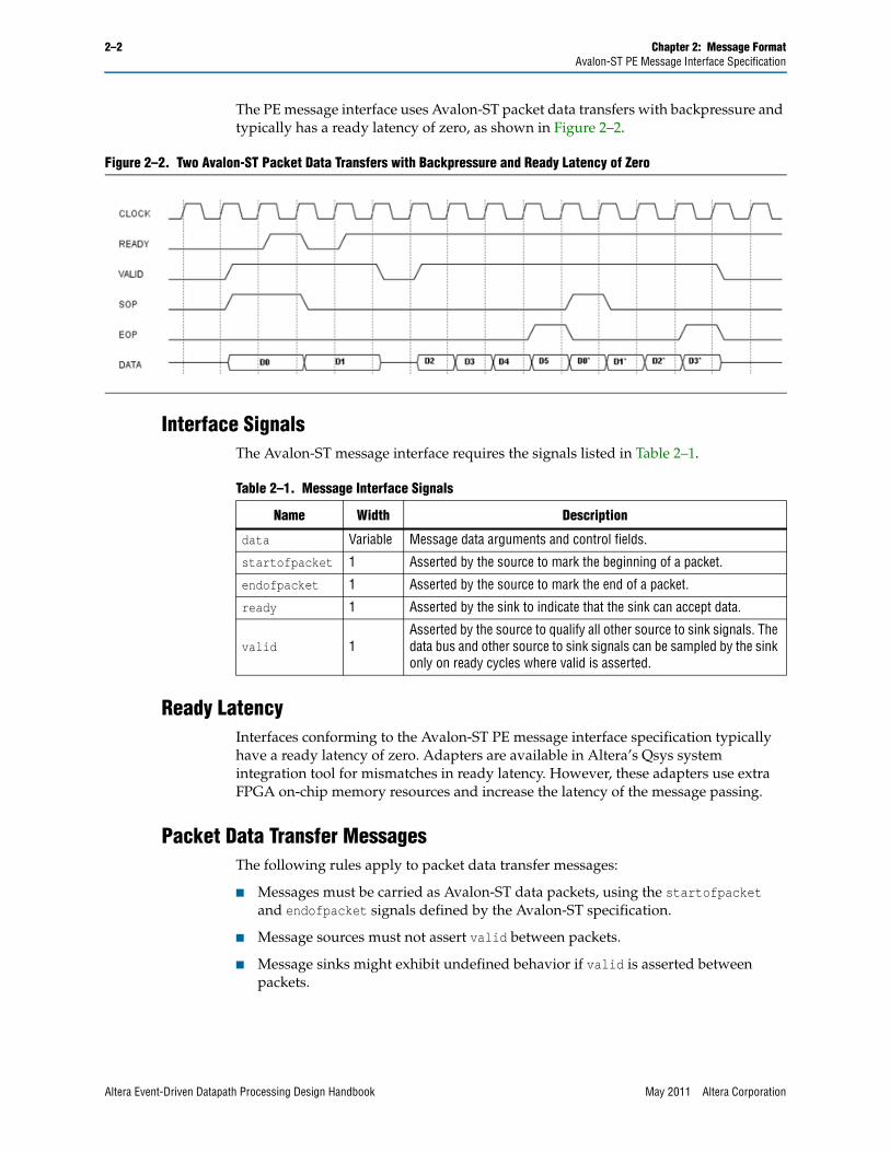
The PE message interface uses Avalon-ST packet data transfers with backpressure and typically has a ready latency of zero, as shown in Figure 2–2.
Interface SignalsThe Avalon-ST message interface requires the signals listed in Table 2–1.
Ready LatencyInterfaces conforming to the Avalon-ST PE message interface specification typically have a ready latency of zero. Adapters are available in Altera’s Qsys system integration tool for mismatches in ready latency. However, these adapters use extra FPGA on-chip memory resources and increase the latency of the message passing.
Packet Data Transfer MessagesThe following rules apply to packet data transfer messages:
■ Messages must be carried as Avalon-ST data packets, using the startofpacket and endofpacket signals defined by the Avalon-ST specification.
■ Message sources must not assert valid between packets.
■ Message sinks might exhibit undefined behavior if valid is asserted between packets.
Figure 2–2. Two Avalon-ST Packet Data Transfers with Backpressure and Ready Latency of Zero
Table 2–1. Message Interface Signals
Name Width Description
data Variable Message data arguments and control fields.
startofpacket 1 Asserted by the source to mark the beginning of a packet.
endofpacket 1 Asserted by the source to mark the end of a packet.
ready 1 Asserted by the sink to indicate that the sink can accept data.
valid 1Asserted by the source to qualify all other source to sink signals. The data bus and other source to sink signals can be sampled by the sink only on ready cycles where valid is asserted.
Altera Event-Driven Datapath Processing Design Handbook May 2011 Altera Corporation

Chapter 2: Message Format 2–3Avalon-ST PE Message Interface Specification
Avalon-ST PE Message FormatAvalon-ST PE messages consist of one or more data arguments and a control word. The data arguments contain the message data and the control word contains control information. Each data argument is 32 bits wide (unless adjusted in advanced cases). The control word width is user-configurable.
1 The message interconnect and all PEs connected to the message interconnect must use the same control word format. Altera recommends collaboration between your hardware and software engineers to design your control word format before developing the hardware and software. For Nios II DPX datapath processor systems, the default control word format is suitable without modification for most applications. For information about the Nios II DPX datapath processor message format, refer to “External Interfaces Tab” in the Instantiating the Nios II DPX Datapath Processor chapter in the Nios II DPX Hardware Reference section of the Nios II DPX Datapath Processor Handbook.
Control WordThe control word contains the control information in a message and consists of one or more of the control fields shown in Table 2–2. Specific systems conforming to this specification might require some or all of the fields to be present.
The width of the control word depends on the control word fields you use and the width you specify for each field. Table 2–3 shows a 26-bit example control word.
Table 2–2. Control Word Fields
Field Name Description
destinationContains the processing element ID of the destination PE, specifying which PE the message should be routed to by the message interconnect.
source Contains the processing element ID of the PE that sent the message.
taskid Specifies the operation to be carried out by the destination PE.
context Contains the context of the message. (1)
user Not defined and available for use by the user.
flags Reserved for use by Altera to carry message flags.
Notes to Table 2–2:(1) In Nios II DPX systems, this field carries the context ID.
Table 2–3. Example Control Word
25 24 23 22 21 20 19 18 17 16 15 14 13 12 11 10 9 8 7 6 5 4 3 2 1 0
destination source taskid context user
May 2011 Altera Corporation Altera Event-Driven Datapath Processing Design Handbook
2–4 Chapter 2: Message FormatMessage Transmission
For future scalability, your control word total width must be defined independently to allow for empty fields that have not yet been defined and for adjustments to field sizes as future needs arise. Table 2–4 shows a 30-bit example expandable control word that currently has only 21 bits defined.
The following rules allow PEs to interoperate if you need to scale your system in future:
■ Message sinks must tolerate unknown bits in the control word. Design a message sink to extract the control fields that it understands and ignore the other bits.
■ Message sources should drive any unknown control word bits to zero.
■ When additional control fields are added in future, PEs that use those fields need to consider the possibility that older PEs might set the new control fields to zero.
Data ArgumentsData arguments carry the data in a message. For example, data arguments for a task could be a location and length of a packet in memory. The following rules apply to data arguments:
■ Each message must carry one or more data arguments. In theory, there is no limit to the number of arguments you can send in a message. In practice, requirements of the PEs or the message interconnect might impose limitations. For a list of potential PE restrictions, refer to “System Considerations” on page 4–6.
■ Each data argument is normally 32 bits wide. Some advanced cases can adjust this width.
■ Arrange multiple data arguments in a message in big endian order, with the lowest-order (highest-numbered) argument in the least significant location.
Message TransmissionData arguments and the control word are carried as subfields in the data signal. The control word must reside in the most significant bits of the data signal. Data arguments must reside in the least significant bits of the data signal. Table 2–5 shows a data symbol containing a control word and one data argument.
Table 2–4. Example Control Word with Future Expansion
29 28 27 26 25 24 23 22 21 20 19 18 17 16 15 14 13 12 11 10 9 8 7 6 5 4 3 2 1 0
source destination taskid user flags
Table 2–5. One-Argument Data Symbol
MSB ... 32 31 ... 0
control arg0
Altera Event-Driven Datapath Processing Design Handbook May 2011 Altera Corporation

Chapter 2: Message Format 2–5Message Transmission
The data signal must carry exactly one symbol per beat. The data arguments update in each beat, while the control word remains constant throughout the message. Figure 2–3 shows the transmission of a message containing a control word and one data argument per beat.
The message shown in Figure 2–3 transmits eight data arguments in eight cycles. The lower part of the data signal, data[31:0], transmits the data arguments, sending a new argument every beat. The upper part of the data signal, data[63:32], transmits the control word, which stays constant throughout the entire message transmission.
1 Figure 2–3 shows the control word as 32 bits wide. However, there is no width size requirement for the control word. The size of the control word must be provided by the PE as a synthesis time parameter and depends on the number of fields used and the size of those fields. For more information, refer to “Control Word” on page 2–3.
To create high-bandwidth interfaces, transmit multiple data arguments per beat. The data signal must be wide enough to hold multiple arguments and a single copy of the control word.
The format of a data symbol with multiple arguments has the control word in the most significant bits, followed by a subfield for identifying empty arguments in the final cycle of the message transmission, followed by the data arguments. The arguments are ordered in big endian format. Table 2–6 shows a data symbol containing a control word, a 1-bit empty subfield, and two data arguments.
The empty subfield is required whenever multiple arguments are present in the data signal. The empty subfield indicates the number of arguments that are empty during the last cycle of the message transmission.
The empty subfield has the same semantics as the Avalon-ST empty signal, but is applied to the arguments subfield, rather than the whole data signal.
Figure 2–3. Message with One Data Argument per Beat
Table 2–6. Two-Argument Data Symbol
MSB ... 65 64 63 ... 32 31 ... 0
control empty arg0 arg1
May 2011 Altera Corporation Altera Event-Driven Datapath Processing Design Handbook

2–6 Chapter 2: Message FormatMessage Transmission
The following rules apply to the empty subfield:
■ When multiple data arguments are carried in the data signal, the empty subfield must exist in the data signal. When only a single data argument is carried, the empty subfield must not exist in the data signal.
■ When the empty subfield exists, it must reside in the data signal between the data arguments and control word.
■ Where provided, the bit width of the empty subfield must be ceiling(log2(data arguments per beat)).
■ The empty subfield is only valid when the endofpacket signal is asserted.
■ When the empty subfield exists, message sources must drive it with a value indicating the number of empty data arguments carried in the last beat of each message. There is no need to drive it with a valid value at other times.
■ The empty subfield is required even if the message being passed has no empty data arguments. In this case, set the empty subfield to zero.
Figure 2–4 shows the transmission of a message containing a control word, a 1-bit empty subfield, and two data arguments per beat.
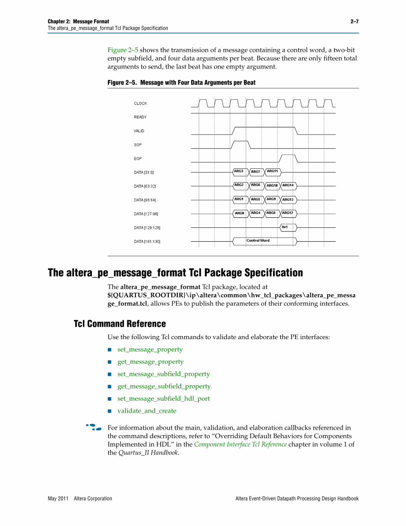
Because there are only fifteen total arguments to send, the last beat has one empty argument. The empty subfield goes high in the last cycle to indicate no data in data[31:0].
Table 2–7 shows a data symbol containing a control word, a two-bit empty subfield, and four data arguments. Two bits are required for the empty subfield because up to three arguments could be empty in the last cycle of the message transmission.
Figure 2–4. Message with Two Data Arguments per Beat
Table 2–7. Four-Argument Data Symbol
MSB ... 130 129 128 127 ... 96 95 ... 64 63 ... 32 31 ... 0
control empty arg0 arg1 arg2 arg3
Altera Event-Driven Datapath Processing Design Handbook May 2011 Altera Corporation
Chapter 2: Message Format 2–7The altera_pe_message_format Tcl Package Specification
Figure 2–5 shows the transmission of a message containing a control word, a two-bit empty subfield, and four data arguments per beat. Because there are only fifteen total arguments to send, the last beat has one empty argument.
The altera_pe_message_format Tcl Package SpecificationThe altera_pe_message_format Tcl package, located at ${QUARTUS_ROOTDIR}\ip\altera\common\hw_tcl_packages\altera_pe_message_format.tcl, allows PEs to publish the parameters of their conforming interfaces.
Tcl Command ReferenceUse the following Tcl commands to validate and elaborate the PE interfaces:
■ set_message_property
■ get_message_property
■ set_message_subfield_property
■ get_message_subfield_property
■ set_message_subfield_hdl_port
■ validate_and_create
f For information about the main, validation, and elaboration callbacks referenced in the command descriptions, refer to “Overriding Default Behaviors for Components Implemented in HDL” in the Component Interface Tcl Reference chapter in volume 1 of the Quartus_II Handbook.
Figure 2–5. Message with Four Data Arguments per Beat
May 2011 Altera Corporation Altera Event-Driven Datapath Processing Design Handbook

2–8 Chapter 2: Message FormatThe altera_pe_message_format Tcl Package Specification
set_message_property
Table 2–8 shows the available message properties.
get_message_property
Description: Sets a property of a message interface
Callback availability: Main, validation, elaboration
Usage: set_message_property <interfaceName> <propertyName> <value>
Returns: The value set
Arguments: ■ interfaceName—The name of the message interface whose property is to be set.
■ propertyName—The name of the property whose value you want to set. Refer to Table 2–8 for a list of the supported properties.
■ value—The value to set.
Example: set_message_property msg_out PEID 4
Table 2–8. Message Properties
Name Type Default Description
PEID Integer –1 Assigns the processing element ID associated with the interface. A value of –1 indicates that the PEID is not set.
ZERO_OUTPUT_PORT String “”
Specifies the name of a one bit HDL output port that is driven to a constant value of zero. This port is required for message sources that use the set_message_subfield_hdl_port function and is used to fill any gaps in the data signal constructed using FRAGMENT_LIST.
UNUSED_INPUT_PORT String “”
Specifies the name of an HDL input port of parameterizable width that is unused by the HDL. This port is required for message sinks that use the set_message_subfield_hdl_port function and is used to terminate any gaps in the data signal constructed using FRAGMENT_LIST.
UNUSED_INPUT_WIDTH_PARAM String “”
Specifies the name of the parameter that specifies the width of the unused input port specified in the UNUSED_INPUT_PORT property. This parameter is required for message sinks that use the set_message_subfield_hdl_port function.
Description: Retrieves a property of a message interface
Callback availability: Main, validation, elaboration
Usage: get_message_property <interfaceName> <propertyName>
Returns: The value of the property
Arguments: ■ interfaceName—The name of the message interface whose property is to be retrieved.
■ propertyName—The name of the property whose value you want to retrieve. Refer to Table 2–8 for a list of the supported properties.
■ value—The value to set.
Example: get_message_property msg_out PEID
Altera Event-Driven Datapath Processing Design Handbook May 2011 Altera Corporation
Chapter 2: Message Format 2–9The altera_pe_message_format Tcl Package Specification
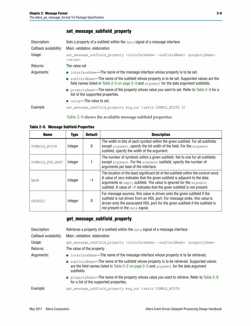
set_message_subfield_property
Table 2–9 shows the available message subfield properties.
get_message_subfield_property
Description: Sets a property of a subfield within the data signal of a message interface
Callback availability: Main, validation, elaboration
Usage: set_message_subfield_property <interfaceName> <subfieldName> <propertyName> <value>
Returns: The value set
Arguments: ■ interfaceName—The name of the message interface whose property is to be set.
■ subfieldName—The name of the subfield whose property is to be set. Supported values are the field names listed in Table 2–2 on page 2–3 and argument for the data argument subfields.
■ propertyName—The name of the property whose value you want to set. Refer to Table 2–9 for a list of the supported properties.
■ value—The value to set.
Example: set_message_subfield_property msg_out taskid SYMBOL_WIDTH 32
Table 2–9. Message Subfield Properties
Name Type Default Description
SYMBOLS_WIDTH Integer 0The width in bits of each symbol within the given subfield. For all subfields except argument, specify the bit width of the field. For the argument subfield, specify the width of the argument.
SYMBOLS_PER_BEAT Integer 1The number of symbols within a given subfield. Set to one for all subfields except argument. For the argument subfield, specify the number of arguments per beat of the interface.
BASE Integer –1
The location of the least significant bit of the subfield within the control word. A value of zero indicates that the given subfield is adjacent to the data arguments or empty subfield. The value is ignored for the argument subfield. A value of –1 indicates that the given subfield is not present.
DEFAULT Integer 0
For message sources, this value is driven onto the given subfield if the subfield is not driven from an HDL port. For message sinks, this value is driven onto the associated HDL port for the given subfield if the subfield is not present in the data signal.
Description: Retrieves a property of a subfield within the data signal of a message interface
Callback availability: Main, validation, elaboration
Usage: get_message_subfield_property <interfaceName> <subfieldName> <propertyName>
Returns: The value of the property
Arguments: ■ interfaceName—The name of the message interface whose property is to be retrieved.
■ subfieldName—The name of the subfield whose property is to be retrieved. Supported values are the field names listed in Table 2–2 on page 2–3 and argument for the data argument subfields.
■ propertyName—The name of the property whose value you want to retrieve. Refer to Table 2–9 for a list of the supported properties.
Example: get_message_subfield_property msg_out taskid SYMBOL_WIDTH
May 2011 Altera Corporation Altera Event-Driven Datapath Processing Design Handbook

2–10 Chapter 2: Message FormatThe altera_pe_message_format Tcl Package Specification
set_message_subfield_hdl_port
validate_and_create
Description: Binds a port on your HDL module to a subfield within the data signal of a message interface.
This command is optional and results in the data signal for the given interface to be constructed from HDL signals using the FRAGMENT_LIST port property. Do not combine this command with manual use of the FRAGMENT_LIST port property on the associated data signal.
Mapping of the data signal to HDL ports takes place when the validate_and_create command is executed. For more information, refer to “Binding HDL ports to the Data Port” on page 2–11.
Callback availability: Main, validation, elaboration
Usage: set_message_subfield_hdl_port <interfaceName> <subfieldName> <portString>
Returns: The port string
Arguments: ■ interfaceName—The name of the message interface whose data signal is being configured.
■ subfieldName—The name of the data signal subfield to map to the HDL port. Supported values are the field names listed in Table 2–2 on page 2–3, argument for the data argument subfields, and argumentEmpty for the empty subfield.
■ portString—The string defining the HDL port name and bit range to map to the specified subfield. This string has the following syntax:
<hdl_port_name>[@<msb>:<lsb>]
where <hdl_port_name> is the name of the HDL port, <msb> is the most significant bit of the HDL port to use, and <lsb> is the least significant bit of the HDL port to use.
If portString contains only the HDL port name, then the width of the HDL port must match the width of the subfield.
If portString contains a bit range, then the width of the range must match the width of the subfield.
Example: set_message_subfield_hdl_port msg_out taskid "avs_msgout_taskid@7:0"
Description: Performs the following actions:
■ Validates the interface, as described in “Validation of Message Interfaces”.
■ Binds the data signal to HDL ports, as described in “Binding HDL ports to the Data Port” on page 2–11.
■ Publishes information about the interface to the SOPC Information File (.sopcinfo) via interface assignments for use by downstream tools.
validate_and_create must be the last command called when describing an interface.
Callback availability: Validation, elaboration
Usage: validate_and_create <interfaceName>
Returns: A boolean true value if interface validation and creation is successful; false otherwise.
Arguments: ■ interfaceName—The name of the message interface to validate and create.
Example: validate_and_create msg_out
Altera Event-Driven Datapath Processing Design Handbook May 2011 Altera Corporation

Chapter 2: Message Format 2–11The altera_pe_message_format Tcl Package Specification
Validation of Message InterfacesThe validate_and_create command performs the following checks to ensure that the given interface correctly describes a valid message interface:
■ Checks that the interface exists.
■ Checks that the interface has the ports listed in Table 2–1 on page 2–2.
■ Checks that the user has not set the dataBitsPerSymbol property for this interface and sets the dataBitsPerSymbol property to match the data signal width.
■ Checks that the data signal is wide enough to carry the data arguments, the empty subfield (if required), and the control word.
■ Checks that the control fields, data arguments, and empty subfield do not overlap.
■ Checks that the control fields are located at the top of the data signal.
■ Checks that the selected bit range of any bound HDL ports matches the width of the associated subfield for any HDL ports that were bound to the data subfields using the set_message_subfield_hdl_port command.
Binding HDL ports to the Data PortYou can use individual ports on your HDL code for each of the subfields in the data signal. The validate_and_create command constructs the data port from HDL ports based on the information provided by the set_message_subfield_hdl_port command. It is your responsibility to first define the data port using the add_interface_port command. For example:
add_interface_port msg_in msg_in_data data Input $msg_in_data_width
f For more information about the add_interface_port command, refer to the Component Interface Tcl Reference chapter in volume 1 of the Quartus_II Handbook.
Message SourcesThe following sections describe message source creation for the cases presented.
Data Port Provided from HDL
If the name of the data port given in the add_interface_port command matches the name of an HDL port, the HDL port is configured to directly drive the data port. If the set_message_subfield_hdl_port command is used, an error occurs.
Figure 2–6 shows a message source whose data port is provided in its entirety by an HDL port.
Figure 2–6. Message Source Example
May 2011 Altera Corporation Altera Event-Driven Datapath Processing Design Handbook
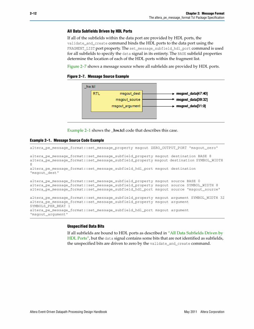
2–12 Chapter 2: Message FormatThe altera_pe_message_format Tcl Package Specification
All Data Subfields Driven by HDL Ports
If all of the subfields within the data port are provided by HDL ports, the validate_and_create command binds the HDL ports to the data port using the FRAGMENT_LIST port property. The set_message_subfield_hdl_port command is used for all subfields to specify the data signal in its entirety. The BASE subfield properties determine the location of each of the HDL ports within the fragment list.
Figure 2–7 shows a message source where all subfields are provided by HDL ports.
Example 2–1 shows the _hw.tcl code that describes this case.
Unspecified Data Bits
If all subfields are bound to HDL ports as described in “All Data Subfields Driven by HDL Ports”, but the data signal contains some bits that are not identified as subfields, the unspecified bits are driven to zero by the validate_and_create command.
Figure 2–7. Message Source Example
Example 2–1. Message Source Code Example
altera_pe_message_format::set_message_property msgout ZERO_OUTPUT_PORT "msgout_zero"
altera_pe_message_format::set_message_subfield_property msgout destination BASE 8altera_pe_message_format::set_message_subfield_property msgout destination SYMBOL_WIDTH 8altera_pe_message_format::set_message_subfield_hdl_port msgout destination "msgout_dest"
altera_pe_message_format::set_message_subfield_property msgout source BASE 0altera_pe_message_format::set_message_subfield_property msgout source SYMBOL_WIDTH 8altera_pe_message_format::set_message_subfield_hdl_port msgout source "msgout_source"
altera_pe_message_format::set_message_subfield_property msgout argument SYMBOL_WIDTH 32altera_pe_message_format::set_message_subfield_property msgout argument SYMBOLS_PER_BEAT 1altera_pe_message_format::set_message_subfield_hdl_port msgout argument "msgout_argument"
Altera Event-Driven Datapath Processing Design Handbook May 2011 Altera Corporation
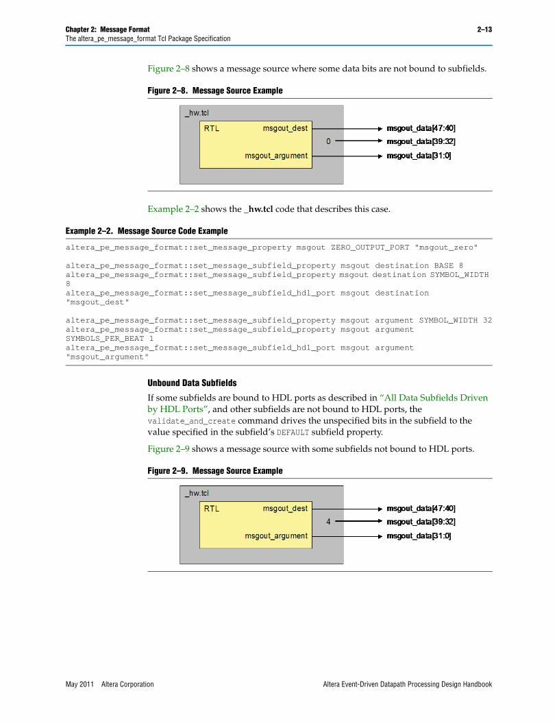
Chapter 2: Message Format 2–13The altera_pe_message_format Tcl Package Specification
Figure 2–8 shows a message source where some data bits are not bound to subfields.
Example 2–2 shows the _hw.tcl code that describes this case.
Unbound Data Subfields
If some subfields are bound to HDL ports as described in “All Data Subfields Driven by HDL Ports”, and other subfields are not bound to HDL ports, the validate_and_create command drives the unspecified bits in the subfield to the value specified in the subfield’s DEFAULT subfield property.
Figure 2–9 shows a message source with some subfields not bound to HDL ports.
Figure 2–8. Message Source Example
Example 2–2. Message Source Code Example
altera_pe_message_format::set_message_property msgout ZERO_OUTPUT_PORT "msgout_zero"
altera_pe_message_format::set_message_subfield_property msgout destination BASE 8altera_pe_message_format::set_message_subfield_property msgout destination SYMBOL_WIDTH 8altera_pe_message_format::set_message_subfield_hdl_port msgout destination "msgout_dest"
altera_pe_message_format::set_message_subfield_property msgout argument SYMBOL_WIDTH 32altera_pe_message_format::set_message_subfield_property msgout argument SYMBOLS_PER_BEAT 1altera_pe_message_format::set_message_subfield_hdl_port msgout argument "msgout_argument"
Figure 2–9. Message Source Example
May 2011 Altera Corporation Altera Event-Driven Datapath Processing Design Handbook

2–14 Chapter 2: Message FormatThe altera_pe_message_format Tcl Package Specification
Example 2–3 shows the _hw.tcl code that describes this case.
Unused HDL Subfield Ports
If some subfields are bound to HDL ports using the set_message_subfield_hdl_port command, but those subfields are not defined in the data signal, the validate_and_create command terminates the corresponding HDL port.
Figure 2–10 shows a message source providing an HDL port for a subfield missing from data signal.
Example 2–4 shows the _hw.tcl code that describes this case.
Example 2–3. Message Source Code Example
altera_pe_message_format::set_message_property msgout ZERO_OUTPUT_PORT "msgout_zero"
altera_pe_message_format::set_message_subfield_property msgout destination BASE 8altera_pe_message_format::set_message_subfield_property msgout destination SYMBOL_WIDTH 8altera_pe_message_format::set_message_subfield_hdl_port msgout destination "msgout_dest"
altera_pe_message_format::set_message_subfield_property msgout source BASE 0altera_pe_message_format::set_message_subfield_property msgout source SYMBOL_WIDTH 8
altera_pe_message_format::set_message_subfield_property msgout argument SYMBOL_WIDTH 32altera_pe_message_format::set_message_subfield_property msgout argument SYMBOLS_PER_BEAT 1altera_pe_message_format::set_message_subfield_hdl_port msgout argument "msgout_argument"
Figure 2–10. Message Source Example
Example 2–4. Message Source Code Example
altera_pe_message_format::set_message_property msgout ZERO_OUTPUT_PORT "msgout_zero"
altera_pe_message_format::set_message_subfield_property msgout destination BASE 8altera_pe_message_format::set_message_subfield_property msgout destination SYMBOL_WIDTH 8altera_pe_message_format::set_message_subfield_hdl_port msgout destination "msgout_dest"
altera_pe_message_format::set_message_subfield_hdl_port msgout user "msgout_user"
altera_pe_message_format::set_message_subfield_property msgout argument SYMBOL_WIDTH 32altera_pe_message_format::set_message_subfield_property msgout argument SYMBOLS_PER_BEAT 1altera_pe_message_format::set_message_subfield_hdl_port msgout argument "msgout_argument"
Altera Event-Driven Datapath Processing Design Handbook May 2011 Altera Corporation

Chapter 2: Message Format 2–15The altera_pe_message_format Tcl Package Specification
Message SinksThe following sections describe message sink creation for the cases presented.
Data Port Provided from HDL
If the name of the data port given in the add_interface_port command matches the name of an HDL port, the HDL port directly connects to the data port. If the set_message_subfield_hdl_port command is used, an error occurs.
Figure 2–11 shows a message sink whose data port is provided in its entirety by an HDL port.
All Data Subfields Connected to HDL Ports
If HDL ports are specified for all of the subfields within the data port, the validate_and_create command binds the HDL ports to the data port using the FRAGMENT_LIST port property. The set_message_subfield_hdl_port command is used for all subfields to specify the data signal in its entirety. The BASE subfield properties are used to determine the location of each of the HDL ports within the fragment list.
Figure 2–12 shows a message sink where all subfields are connected to HDL ports.
Figure 2–11. Message Sink Example
Figure 2–12. Message Sink Example
May 2011 Altera Corporation Altera Event-Driven Datapath Processing Design Handbook

2–16 Chapter 2: Message FormatThe altera_pe_message_format Tcl Package Specification
Example 2–5 shows the _hw.tcl code that describes this case.
Unspecified Data Bits
If all subfields are bound to HDL ports as described in “All Data Subfields Connected to HDL Ports”, but the data signal contains some bits which are not identified as subfields, the validate_and_create command terminates the unspecified bits.
Figure 2–13 shows a message sink where some data bits are not bound to subfields.
Example 2–6 shows the _hw.tcl code that describes this case.
Unbound Data Subfields
If some subfields are bound to HDL ports as described in “All Data Subfields Connected to HDL Ports”, and other subfields are not bound to HDL ports, the validate_and_create command terminates the unspecified bits.
Example 2–5. Message Sink Code Example
altera_pe_message_format::set_message_property msgin UNUSED_INPUT_PORT "msgin_unused"altera_pe_message_format::set_message_property msgin UNUSED_INPUT_WIDTH_PARAM \"msgin_unused_width"
altera_pe_message_format::set_message_subfield_property msgin destination BASE 8altera_pe_message_format::set_message_subfield_property msgin destination SYMBOL_WIDTH 8altera_pe_message_format::set_message_subfield_hdl_port msgin destination "msgin_dest"
altera_pe_message_format::set_message_subfield_property msgin source BASE 0altera_pe_message_format::set_message_subfield_property msgin source SYMBOL_WIDTH 8altera_pe_message_format::set_message_subfield_hdl_port msgin source "msgin_source"
altera_pe_message_format::set_message_subfield_property msgin argument SYMBOL_WIDTH 32altera_pe_message_format::set_message_subfield_property msgin argument SYMBOLS_PER_BEAT 1altera_pe_message_format::set_message_subfield_hdl_port msgin argument "msgin_argument"
Figure 2–13. Message Sink Example
Example 2–6. Message Sink Code Example
altera_pe_message_format::set_message_property msgin UNUSED_INPUT_PORT "msgin_unused"altera_pe_message_format::set_message_property msgin UNUSED_INPUT_WIDTH_PARAM \"msgin_unused_width"
altera_pe_message_format::set_message_subfield_property msgin destination BASE 8altera_pe_message_format::set_message_subfield_property msgin destination SYMBOL_WIDTH 8altera_pe_message_format::set_message_subfield_hdl_port msgin destination "msgin_dest"
altera_pe_message_format::set_message_subfield_property msgin argument SYMBOL_WIDTH 32altera_pe_message_format::set_message_subfield_property msgin argument SYMBOLS_PER_BEAT 1altera_pe_message_format::set_message_subfield_hdl_port msgin argument "msgin_argument"
Altera Event-Driven Datapath Processing Design Handbook May 2011 Altera Corporation

Chapter 2: Message Format 2–17The altera_pe_message_format Tcl Package Specification
Figure 2–14 shows a message sink with some subfields not bound to HDL ports.
Example 2–7 shows the _hw.tcl code that describes this case.
Unused HDL Subfield Ports
If some subfields are bound to HDL ports using the set_message_subfield_hdl_port command, but those subfields are not defined in the data signal, the validate_and_create command drives the corresponding HDL port to a default value specified in the subfield’s DEFAULT subfield property.
Figure 2–15 shows a message sink providing an HDL port for a subfield missing from data signal.
Figure 2–14. Message Sink Example
Example 2–7. Message Sink Code Example
altera_pe_message_format::set_message_property msgin UNUSED_INPUT_PORT "msgin_unused"altera_pe_message_format::set_message_property msgin UNUSED_INPUT_WIDTH_PARAM \"msgin_unused_width"
altera_pe_message_format::set_message_subfield_property msgin destination BASE 8altera_pe_message_format::set_message_subfield_property msgin destination SYMBOL_WIDTH 8altera_pe_message_format::set_message_subfield_hdl_port msgin destination "msgin_dest"
altera_pe_message_format::set_message_subfield_property msgin source BASE 0altera_pe_message_format::set_message_subfield_property msgin source SYMBOL_WIDTH 8
altera_pe_message_format::set_message_subfield_property msgin argument SYMBOL_WIDTH 32altera_pe_message_format::set_message_subfield_property msgin argument SYMBOLS_PER_BEAT 1altera_pe_message_format::set_message_subfield_hdl_port msgin argument "msgin_argument"
Figure 2–15. Message Sink Example
May 2011 Altera Corporation Altera Event-Driven Datapath Processing Design Handbook
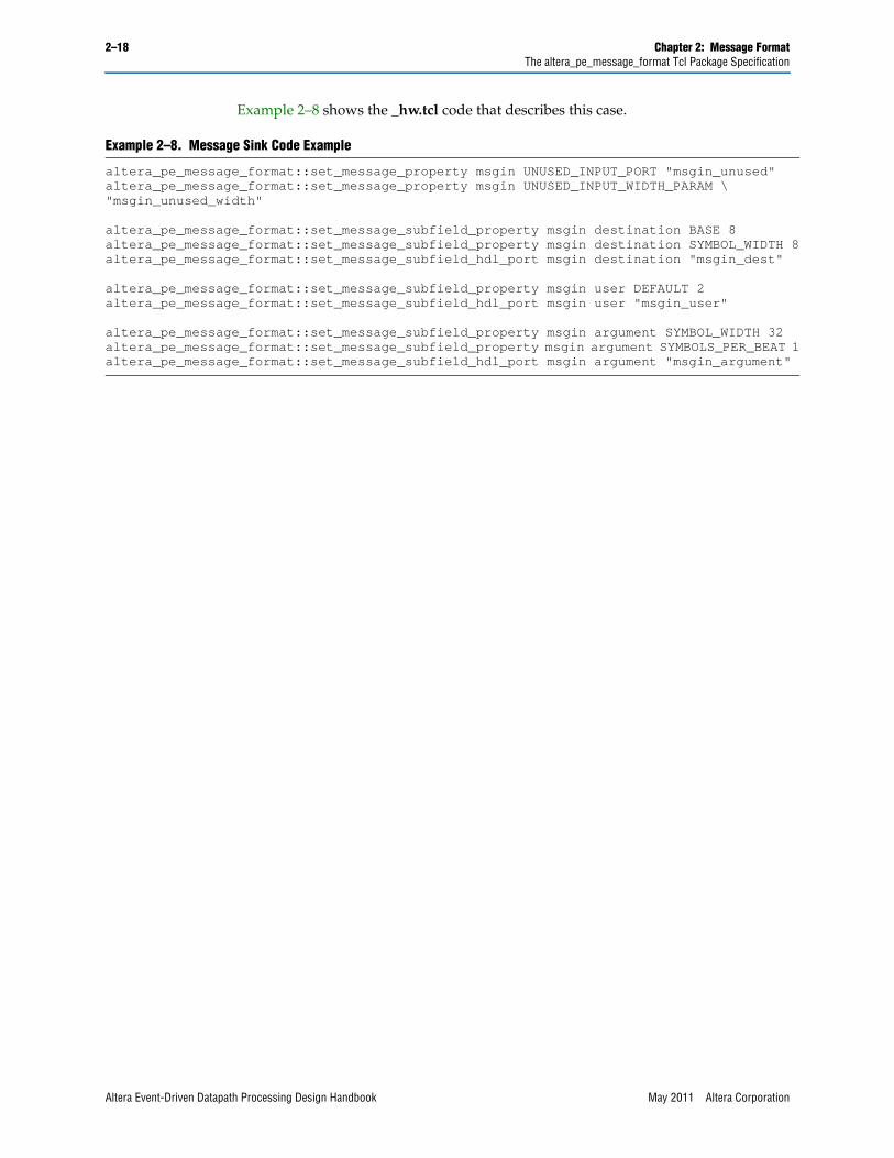
2–18 Chapter 2: Message FormatThe altera_pe_message_format Tcl Package Specification
Example 2–8 shows the _hw.tcl code that describes this case.
Example 2–8. Message Sink Code Example
altera_pe_message_format::set_message_property msgin UNUSED_INPUT_PORT "msgin_unused"altera_pe_message_format::set_message_property msgin UNUSED_INPUT_WIDTH_PARAM \"msgin_unused_width"
altera_pe_message_format::set_message_subfield_property msgin destination BASE 8altera_pe_message_format::set_message_subfield_property msgin destination SYMBOL_WIDTH 8altera_pe_message_format::set_message_subfield_hdl_port msgin destination "msgin_dest"
altera_pe_message_format::set_message_subfield_property msgin user DEFAULT 2altera_pe_message_format::set_message_subfield_hdl_port msgin user "msgin_user"
altera_pe_message_format::set_message_subfield_property msgin argument SYMBOL_WIDTH 32altera_pe_message_format::set_message_subfield_property msgin argument SYMBOLS_PER_BEAT 1altera_pe_message_format::set_message_subfield_hdl_port msgin argument "msgin_argument"
Altera Event-Driven Datapath Processing Design Handbook May 2011 Altera Corporation
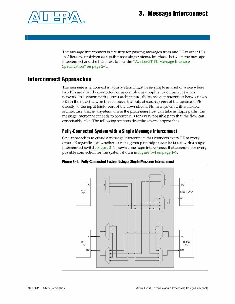
May 2011 Altera Corporation
3. Message Interconnect
The message interconnect is circuitry for passing messages from one PE to other PEs. In Altera event-driven datapath processing systems, interfaces between the message interconnect and the PEs must follow the “Avalon-ST PE Message Interface Specification” on page 2–1.
Interconnect ApproachesThe message interconnect in your system might be as simple as a set of wires where two PEs are directly connected, or as complex as a sophisticated packet switch network. In a system with a linear architecture, the message interconnect between two PEs in the flow is a wire that connects the output (source) port of the upstream PE directly to the input (sink) port of the downstream PE. In a system with a flexible architecture, that is, a system where the processing flow can take multiple paths, the message interconnect needs to connect PEs for every possible path that the flow can conceivably take. The following sections describe several approaches.
Fully-Connected System with a Single Message InterconnectOne approach is to create a message interconnect that connects every PE to every other PE regardless of whether or not a given path might ever be taken with a single interconnect switch. Figure 3–1 shows a message interconnect that accounts for every possible connection for the system shown in Figure 1–4 on page 1–9.
Figure 3–1. Fully-Connected System Using a Single Message Interconnect
Altera Event-Driven Datapath Processing Design Handbook

3–2 Chapter 3: Message InterconnectInterconnect Approaches
The system contains four PEs. The message interconnect connecting the PEs has four message input ports but only three message output ports, because the input PE only sends messages. This approach is useful for designs that might change during the course of development and for designs with a small number of PEs. The approach is simple to implement; the entire message interconnect is one “Processing Element Message Switch” on page 3–3.
Required Connections with Multiple SwitchesFor many reasons, such as size reduction and efficiency, you might choose to optimize the message interconnect for your system by creating a message interconnect that connects only the PEs that need to be connected.
One approach is to use multiple small, dedicated message interconnect switches. The system shown in Figure 1–4 on page 1–9 is a good optimization candidate. Each PE (including the processor PE) sends messages only to the processor PE and receives messages only from the processor PE. No other message paths are needed.
Figure 3–2 shows an optimized message interconnect, where only the required connections are implemented, reducing the overall size and complexity of the message interconnect.
The message interconnect uses two switches described in “Processing Element Message Switch” on page 3–3. One switch has four inputs and one output, and the other switch has one input and three outputs.
Figure 3–2. Required Connections Using a Multiple Message Interconnect Switches
Altera Event-Driven Datapath Processing Design Handbook May 2011 Altera Corporation

Chapter 3: Message Interconnect 3–3Processing Element Message Switch
Fully-Connected System with Multiple InterconnectsFor larger systems, it might be beneficial to use multiple message interconnects that are bridged. This approach decreases the overall size of the message interconnect while still allowing message passing between all PEs at the expense of higher latency for messages that pass through the bridge. Figure 3–3 shows a system connecting all PEs through multiple message interconnects.
Processing Element Message SwitchThe Processing Element Message Switch IP core, shown in Figure 3–1 on page 3–1, provides a customizable message interconnect to pass Avalon-ST PE messages between PEs. Avalon-ST PE messages are Avalon-ST packets, with each packet containing a single complete message. For more information, refer to “Avalon-ST PE Message Interface Specification” on page 2–1.
The Processing Element Message Switch offers the following features:
■ Configurable number of input and output ports
■ Number of message input ports can be different from number of output ports
■ Ability to assign one or more processing element IDs (PEID) to a message output port
■ Configurable routing field in the message control word
■ Partial-crossbar configuration
■ Clock domain crossing
■ Message width adaptation
■ External arbitration
■ Multicast routing
Figure 3–3. Fully-Connected System Using Multiple Message Interconnects
May 2011 Altera Corporation Altera Event-Driven Datapath Processing Design Handbook

3–4 Chapter 3: Message InterconnectProcessing Element Message Switch
The Processing Element Message Switch consists of dedicated input ports, dedicated output ports, and a configurable crossbar switch fabric, allowing every input port access to every output port. The message routing is dictated by the routing field in the message's control word. Each output port is assigned to one or more values, which are read from the routing field in the control word.
The routing ID is an arbitrary set of bits selected from the message control word to select which switch output port to use. The routing ID can comprise any subset or combination of bits from the destination, the context, the flags, or the other fields. For example, some multicore systems route messages to different cores depending on whether the CID is odd or even. In this case the LSB of the CID is included in the routing ID field. However, in simple systems, the destination PEID is sufficient.
The Processing Element Message Switch receives incoming messages through the input (sink) ports. Inside the switch, the message passes through a routing element which reads the routing field of the control word and determines where to route the message. The message is then routed through a crossbar switch to the appropriate output (source) port.
The number of data arguments in the Avalon-ST message format can vary for each input and output message port. The Processing Element Message Switch automatically adapts the incoming port message to the outgoing port. When the number of data arguments for an input port is less than the number of data arguments for an output port, the switch buffers the data until enough messages are received. When the number of data arguments for an input port is greater than the number of data arguments for an output port, the switch sends the data out in multiple messages. For specific setup information, including restrictions, refer to the Input’s Number of data arguments and Output’s Number of data arguments parameter descriptions and the footnotes in Table 3–1. For information about data argument transmission, refer to “Message Transmission” on page 2–4.
ParametersIn Qsys, the Processing Element Message Switch parameter editor is available in the component library under the Message Interconnect category. Table 3–1 shows the Processing Element Message Switch parameters available in the parameter editor.
Table 3–1. Processing Element Message Switch Parameters (Part 1 of 3)
Name Value Description
Packet format
Control word width Variable Specifies the width in bits of the control word in the message.
Routing field base
0 to (Control word width – 1)
Specifies the location of the LSB of the routing field relative to the LSB of the control word, that is, LSB of the routing field = Routing field base + Data argument width. For example, a Routing field base value of six for a system with a data argument width of 32 indicates that the LSB of the routing field is at bit position 38. For a typical system, align the LSB of the routing field to the base of the destination subfield.
Routing field width
0 to (Control word width – Routing field base)
Specifies the width in bits of the routing field. Routing field width is typically set to the width of the destination subfield. When zero, the switch forwards every message.
Altera Event-Driven Datapath Processing Design Handbook May 2011 Altera Corporation
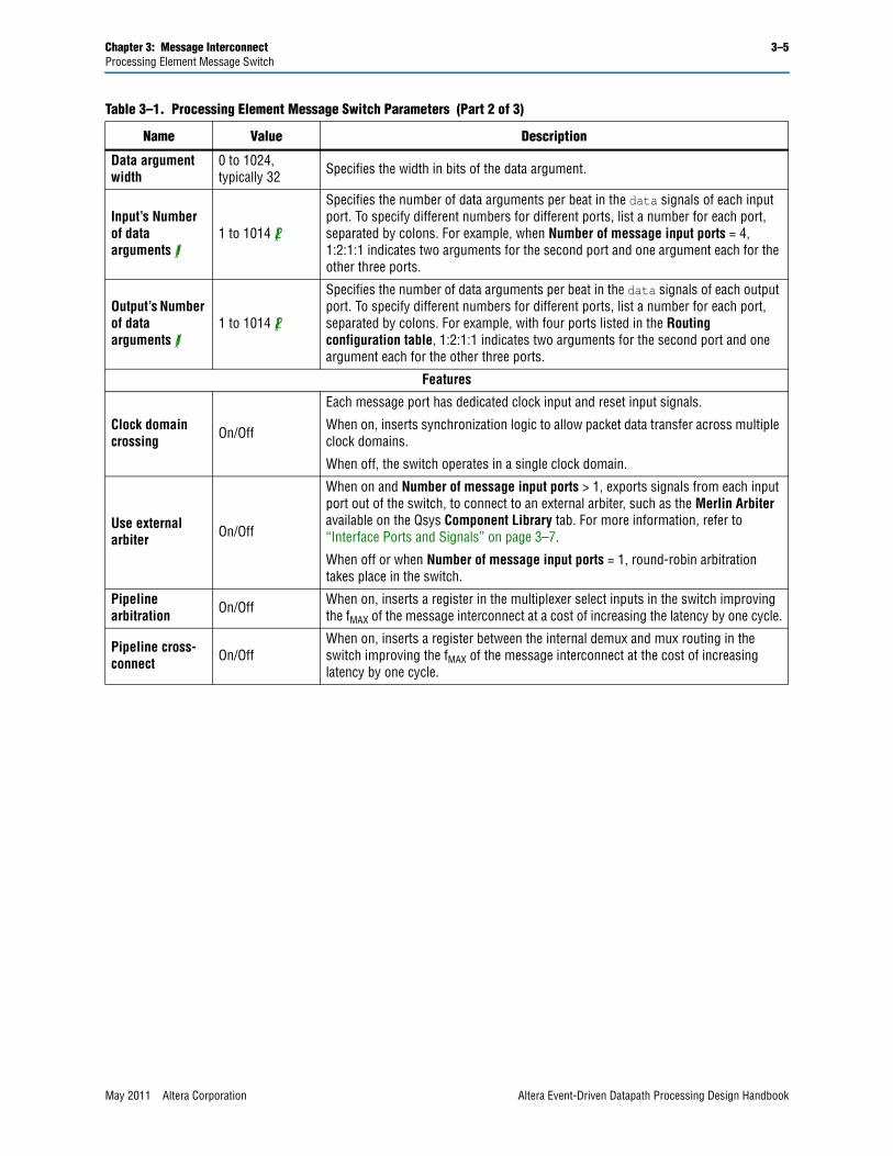
Chapter 3: Message Interconnect 3–5Processing Element Message Switch
Data argument width
0 to 1024, typically 32 Specifies the width in bits of the data argument.
Input’s Number of data arguments (1)
1 to 1014 (2)
Specifies the number of data arguments per beat in the data signals of each input port. To specify different numbers for different ports, list a number for each port, separated by colons. For example, when Number of message input ports = 4, 1:2:1:1 indicates two arguments for the second port and one argument each for the other three ports.
Output’s Number of data arguments (1)
1 to 1014 (2)
Specifies the number of data arguments per beat in the data signals of each output port. To specify different numbers for different ports, list a number for each port, separated by colons. For example, with four ports listed in the Routing configuration table, 1:2:1:1 indicates two arguments for the second port and one argument each for the other three ports.
Features
Clock domain crossing On/Off
Each message port has dedicated clock input and reset input signals.
When on, inserts synchronization logic to allow packet data transfer across multiple clock domains.
When off, the switch operates in a single clock domain.
Use external arbiter On/Off
When on and Number of message input ports > 1, exports signals from each input port out of the switch, to connect to an external arbiter, such as the Merlin Arbiter available on the Qsys Component Library tab. For more information, refer to “Interface Ports and Signals” on page 3–7.
When off or when Number of message input ports = 1, round-robin arbitration takes place in the switch.
Pipeline arbitration On/Off When on, inserts a register in the multiplexer select inputs in the switch improving
the fMAX of the message interconnect at a cost of increasing the latency by one cycle.
Pipeline cross-connect On/Off
When on, inserts a register between the internal demux and mux routing in the switch improving the fMAX of the message interconnect at the cost of increasing latency by one cycle.
Table 3–1. Processing Element Message Switch Parameters (Part 2 of 3)
Name Value Description
May 2011 Altera Corporation Altera Event-Driven Datapath Processing Design Handbook

3–6 Chapter 3: Message InterconnectProcessing Element Message Switch
Cross-connect information
0, x, X, or a power of two
Enables and disables connections in the switch fabric, and specifies the depth of the cross-connection FIFO buffers. Use the following formatting conventions to specify the connections in the switch:
■ To create a full-crossbar switch with consistent FIFO buffer depths, specify a single number (power of two) to indicate the depth at all cross-connections. Enter 0 to remove the buffer from the full-crossbar switch.
■ To create a full-crossbar switch with differing FIFO buffer depths, list the entire matrix using the [<in0_out0>: ... :<in0_outM>] [..] [<inN_out0>: ... :<inN_outM>] format, and specify a separate number for each cross-connection to indicate the FIFO buffer depth at that cross-connection. Enter 0 to indicate no buffer.
For example, [1:2] [1:2] [1:2] [1:0] represents a four-input-port, two-output-port switch with a buffer depth of one for every connection involving the first output port, and a buffer depth of two for every connection involving the second output port except for the connection from the fourth input port to the second output port, which is routed through the switch but not buffered.
■ To create a partial-crossbar switch, list the entire matrix as described for the full-crossbar switch, and enter x or X to remove unneeded connections.
For example, [1:2] [1:2] [1:2] [1:X] represents the same switch described in the full-crossbar example, except there is no connection from the fourth input port to the second output port.
Cross-connect buffering RAM type
Varies by device Specifies the type of memory to use for buffering. For more information about buffering, refer to “Message Buffering” on page 1–16.
Incoming ports configuration
Number of message input ports
Variable Specifies the number of message input ports.
Outgoing ports configuration
Routing configuration table
Variable
Specifies the message output (source) ports and their routing information. Click the + and - buttons to alter the number of output ports. The following list describes the columns in the table:
■ Message Output Ports—The name of the message output port.
■ Routing Field Value—Associates the output port with one or more routing field values. Typically, the destination subfield is used as the routing field, and each output port is associated with the PEID of the attached PE. If there is only one source port assigned to the message interconnect, no ID is needed.
PEID formats include decimal (prefix with d), hexadecimal (prefix with h), and binary (prefix with b). Wildcards are supported in hexadecimal and binary IDs with the ? character. Separate multiple PEIDs with plus signs.
For example, routing field values 255, 58, 22, and 23 could be represented by hff+d58+b1011?.
Notes to Table 3–1:(1) For each input-output connection pair, the number of input data arguments must be a common multiple of the number of output data
arguments, or vice versa. For example, with four input ports and one output port, when Input’s Number of data arguments is 1:2:3:4, Output’s Number of data arguments can only be 1 or a multiple of 12, because 12 is the least common multiple of 1, 2, 3, and 4.
(2) 1014 = the maximum Avalon-ST interface data bus width (1024) – the maximum empty field width (10). For more information, refer to “Message Transmission” on page 2–4.
Table 3–1. Processing Element Message Switch Parameters (Part 3 of 3)
Name Value Description
Altera Event-Driven Datapath Processing Design Handbook May 2011 Altera Corporation
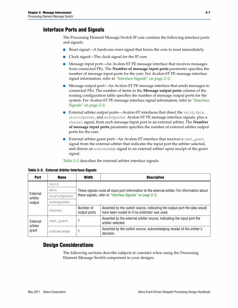
Chapter 3: Message Interconnect 3–7Processing Element Message Switch
Interface Ports and SignalsThe Processing Element Message Switch IP core contains the following interface ports and signals:
■ Reset signal—A hardware reset signal that forces the core to reset immediately.
■ Clock signal—The clock signal for the IP core.
■ Message input port—An Avalon-ST PE message interface that receives messages from connected PEs. The Number of message input ports parameter specifies the number of message input ports for the core. For Avalon-ST PE message interface signal information, refer to “Interface Signals” on page 2–2.
■ Message output port—An Avalon-ST PE message interface that sends messages to connected PEs. The number of items in the Message output ports column of the routing configuration table specifies the number of message output ports for the system. For Avalon-ST PE message interface signal information, refer to “Interface Signals” on page 2–2.
■ External arbiter output ports—Avalon-ST interfaces that direct the valid, data, startofpacket, and endofpacket Avalon-ST PE message interface signals, plus a channel signal, from each message input port to an external arbiter. The Number of message input ports parameter specifies the number of external arbiter output ports for the core.
■ External arbiter grant port—An Avalon-ST interface that receives a next_grant signal from the external arbiter that indicates the input port the arbiter selected, and directs an acknowledge signal to an external arbiter upon receipt of the grant signal.
Table 3–2 describes the external arbiter interface signals.
Design ConsiderationsThe following sections describe subjects to consider when using the Processing Element Message Switch component in your designs.
Table 3–2. External Arbiter Interface Signals
Port Name Width Description
External arbiter output
valid
These signals route all input port information to the external arbiter. For information about these signals, refer to “Interface Signals” on page 2–2.
data
startofpacket
endofpacket
channelNumber of output ports
Asserted by the switch source, indicating the output port the data would have been routed to if no arbitrator was used.
External arbiter grant
next_grant 1 Asserted by the external arbiter source, indicating the input port the arbiter selected.
acknowledge 1 Asserted by the switch source, acknowledging receipt of the arbiter's decision.
May 2011 Altera Corporation Altera Event-Driven Datapath Processing Design Handbook

3–8 Chapter 3: Message InterconnectProcessing Element Message Switch
BackpressureThe flow of messages can stall due to backpressure of the message interconnect. Stalling can happen when an output port receives backpressure by a PE or another message interconnect, or when multiple input ports try to send a message to the same output port. Because the routing path to each port is separate, all other input ports are allowed to pass messages.
To minimize the effect of backpressure on the flow of messages, buffering can be added to the message interconnect. Buffering allows messages to be stored by the message interconnect when a PE is unable to receive a message, removing the backpressure from the sending PE. For more information, refer to “Message Buffering” on page 1–16.
Unmatched Routing FieldWhen a message is received with a routing field which does not match any of the specified routing field values, the associated switch input port locks up. All other ports continue as normal. This behavior is a deliberate design feature, added to aid debugging of this critical error. Without the lockup facility, the system might keep going for some time despite an illegal message.
To clear the lockup condition, reset the Processing Element Message Switch component.
Multiple Message Interconnects in a SystemUsing multiple message interconnects can provide a reduction in resources when compared to a single large crossbar switch. The ability to assign multiple routing field values to a single output port allows multiple message interconnects to be connected.
Using multiple message interconnects can also provide more flexibility to the system designer. For example, replicating PEs can increase processing bandwidth.
Partial-Crossbar SwitchesFor cases where you do not need every input port connected to every output port, you can save resources by creating a partial-crossbar switch that creates only the connections you need. For information, refer to the Cross-connect information parameter in Table 3–1 on page 3–4.
Multicast RoutingProcessing Element Message Switch supports packet multicast routing. You automatically specify multicast routing when you assign the same routing field value to multiple output ports. Incoming packets with a multicast routing value are routed to the output ports that have the same multicast routing value assigned to them.
To send entire multicast packets across the switch without data loss, the depths of all FIFO buffers involved need to be larger than the multicast packet length.
Altera Event-Driven Datapath Processing Design Handbook May 2011 Altera Corporation
May 2011 Altera Corporation
4. Processing Elements
A PE is any component capable of sending or receiving Avalon-ST PE messages in the Altera event-driven datapath processing framework. The main function of a PE is to perform one or more tasks in your overall design. PE tasks can be performed either in hardware, software, or a combination of both.
This chapter describes the requirements to create an Altera event-driven datapath processing PE from any IP core you have developed or purchased from a third party. Developing PEs for the Altera event-driven datapath processing framework includes the following features:
■ A well-defined interface specification for data transfers
■ A GUI to easily add, remove, and modify PEs
■ Altera tools that generate optimum interconnect logic, saving design time and effort
■ Bus functional models (BFM) and component authoring tools
Altera Event-Driven Datapath Processing Design Handbook

4–2 Chapter 4: Processing ElementsDesign Requirements Overview
Figure 4–1 shows an example system with multiple PEs. Each PE has a message interface that connects to a message interconnect. The message interconnect can be generated by Altera tools or custom designed.
Design Requirements OverviewFor an IP core to be an Altera event-driven datapath processing PE, it minimally needs to have message interfaces to send, receive, or send and receive messages. The message interface allows data and control information to pass between PEs either directly or through a message interconnect.
Data moving to and from the PEs might also travel through additional design-specific interfaces, to add functionality such as provide access to shared memory. Design-specific interfaces are not explicitly defined in the message interface, but Altera recommends using common interfaces such as the Avalon Memory-Mapped (Avalon-MM) and Avalon-ST interfaces.
PEs must manage and buffer incoming messages as needed. Use backpressure when the PE is unable to accept new messages. The Avalon-ST interface specification defines signals, parameters, and hand-shaking protocols to manage backpressure during data transfer.
f For information about the Avalon-ST interface, refer to Avalon Interface Specifications.
Figure 4–1. Example Multiple PE System
Computa�onal & Context ID Management
Input Computa�onal Computa�onal
Output
Message Interconnect
Output Context Register I/F (Avalon MM) Input Context Register I/F (Avalon MM)
CID Free List (Avalon ST)
External Data Source
External Data Sink
Message TX (Source)
Message RX (Sink)
Memory Buffer
User Defined Interface User Defined Interface
Processing Element
Altera Event-Driven Datapath Processing Design Handbook May 2011 Altera Corporation

Chapter 4: Processing Elements 4–3Design Requirements Overview
You can use PEs to perform one specific task or fulfill multiple roles. For example, the Nios II DPX datapath processor can run multiple software tasks.
PEs can be designed to perform tasks concurrently (the same task or different tasks) on different sets of data. For example, a dual-core Nios II DPX datapath processor performs up to 16 concurrent tasks by having multiple hardware threads working independently.
Processing Element Types by FunctionAs Figure 4–1 shows, PEs perform many roles in Altera event-driven datapath processing systems. The following sections describe some of the types of PEs.
Input PEsThe input PE provides the interface for data coming into the system. The input PE manages the data flow into the system and buffers as needed. Depending on the desired system topology, the input PE might break up and distribute the input data stream into several substreams.
In systems that use CIDs, the input PE typically requests CIDs from the context management PE and assigns the CIDs to the incoming data. For more information, refer to “Context Management” on page 1–11 and “Context Management PEs” on page 4–4.
In a typical system, the input PE sends but does not receive messages within the system. The interface for receiving data from outside of the system is defined by the user with interfaces such as the Avalon-MM and Avalon-ST interfaces.
Output PEsThe output PE provides the interface for data leaving the system. The output PE manages the data flow leaving the system and frees any buffers as needed.
In systems that use CIDs, the output PE typically sends a message to the context management PE to free the CID of the data leaving the system.
In a typical system, the output PE sends and receives messages within the system. You define the interface for sending data outside of the system with interfaces such as the Avalon-MM and Avalon-ST interfaces.
Computational PEsA typical use of a PE is to perform a computational task. Both hardware and software-programmable PEs can perform computational tasks. The following list gives examples of computational tasks:
■ Counting Ethernet packets
■ Parsing a packet header
■ Scaling a video frame
May 2011 Altera Corporation Altera Event-Driven Datapath Processing Design Handbook

4–4 Chapter 4: Processing ElementsInterfaces
Context Management PEsBecause multiple blocks of data can be processed concurrently, the data context being processed needs to be maintained, ensuring that data is processed independently, in its own context.
A context management PE, such as the Nios II DPX datapath processor, provides a mechanism for maintaining the context of the data using the CID. In a typical system, the input PE requests unique CIDs from the context management PE and assigns a unique CID to each block of data before passing control to other PEs. The context management PE manages CID usage.
When data exits the system through the output PE, the output PE in a typical system informs the context management PE that the CID is no longer needed, allowing the context management PE to free the CID for use with subsequent sets of data.
1 The Nios II DPX datapath processor can act as the context management PE while concurrently serving other roles. Systems that include a Nios II DPX datapath processor do not require separate context management PEs. The processor provides mechanisms for maintaining order of data coming into and out of the system. For more information, refer to the Software Programming Model chapter in the Nios II DPX Software Development section of the Nios II DPX Datapath Processor Handbook.
Flow Control PEsAs described in Chapter 1, Introduction to Altera Event-Driven Datapath Processing, flow control PEs serve an important role in flexible-architecture systems. For information, refer to “Flow Control PEs” on page 1–14.
InterfacesAll defined interfaces in Altera event-driven datapath processing PEs are Avalon-ST or Avalon-MM interfaces.
f For information about Avalon-ST and Avalon-MM interfaces, refer to Avalon Interface Specifications.
The following sections discuss PE interfaces your system can potentially implement.
Message InterfacesThe message interface sends and receives messages passed throughout the system. Typically, the sending PE sends a message requesting the receiving PE to perform a task. Messages can be passed directly between PEs or through a messaging interconnect. Data can be included in the message or referred to by pointers passed in the message.
Altera Event-Driven Datapath Processing Design Handbook May 2011 Altera Corporation

Chapter 4: Processing Elements 4–5Interfaces
Message Clock Interface SignalsThe message interfaces operate in the message clock domain. Table 4–1 shows the message clock interface signals.
Message Interface SignalsThe message interface uses Avalon-ST packet data transfer with backpressure and a ready latency of zero. Table 4–2 shows the required signals and Figure 4–2 shows the timing.
The data signal is design-dependant. The requirements are defined in the “Avalon-ST PE Message Interface Specification” on page 2–1. The data signal consists of two sections, namely, the data arguments and the control word. During the packet transfer, the data arguments are updated each clock cycle while the control word remains constant throughout the data packet transfer.
The data arguments carry data between PEs. The number of data arguments passed is design and PE specific. The control word contains system specific control information. All PEs connected to the same messaging interconnect must contain the same fields in the control word. For more information, refer to “Avalon-ST PE Message Format” on page 2–3.
Table 4–1. Message Clock Interface Signals
Signal Width Direction
clk 1 Input
reset_n 1 Input
Table 4–2. Message Interface Signals
Avalon-ST Signal Width Message Source Direction Message Sink Direction
ready 1 Input Output
valid 1 Output Input
startofpacket 1 Output Input
endofpacket 1 Output Input
data Variable Output Input
Figure 4–2. Message Interface Timing Diagram
May 2011 Altera Corporation Altera Event-Driven Datapath Processing Design Handbook

4–6 Chapter 4: Processing ElementsSystem Considerations
Context Management InterfacesThe “Context Management PEs” on page 4–4 defines the interfaces used to allocate and free CIDs. When a CID request comes in, the context management PE source provides the input PE sink an available CID to assign to incoming blocks of data.
For example, the CID request interface in the Nios II DPX datapath processor uses an Avalon-ST data transfer with backpressure and a ready latency of zero. The CID is passed via the data bus. The input PE asserts a ready signal to read a CID. The context management PE asserts a valid signal to indicate that there is at least one more CID available. While the valid signal is de-asserted, no CIDs are available.
f For more information, including CID request interface signals and timing diagram, refer to the Nios II DPX Architecture chapter in the Nios II DPX Hardware Reference section of the Nios II DPX Datapath Processor Handbook.
Context Register InterfacesAs described in “Registers” on page 1–12, maintaining separate register sets for each context allows tasks access to context-specific data without needing to pass data by message or access data from memory. PEs access context registers through context register interfaces.
For example, the Nios II DPX datapath processor has two context registers interfaces. The input context register interface allows an input PE to load initial context data into the Nios II DPX input context registers. The output context register interface allows an output PE to read processed context data.
f For more information, including context register interface signals and timing diagrams, refer to the Nios II DPX Architecture chapter in the Nios II DPX Hardware Reference section of the Nios II DPX Datapath Processor Handbook.
Other User-Defined InterfacesPEs can have custom-designed, user-defined interfaces to meet the specific needs of your design. The following list describes some uses for user-designed interfaces:
■ External interfaces on the input and output PEs
■ Packet buffer access
■ Memory access
Interfaces inside of a Qsys system need to follow the Avalon-MM or Avalon-ST interface specifications. For interfaces outside of Qsys, Avalon-MM or Avalon-ST interface are recommended but not required.
System ConsiderationsDesigning PEs with system knowledge in mind is essential to correctly integrating PEs into the system. Be sure to consider the following subjects when designing your PEs:
Altera Event-Driven Datapath Processing Design Handbook May 2011 Altera Corporation
Chapter 4: Processing Elements 4–7System Considerations
■ CID—In systems using CIDs, all PEs must manage the context of data and messages going into and out of the PE. The PE must ensure the correct CID is assigned to messages sent from the PE.
■ PEID—For systems using a message interconnect to route messages based on their destination field, each PE within the system must have a unique PEID. The PEID provides the destination information for passing messages. To correctly create messages, the PE must know of the PEID of the PE it wants to send a message to.
■ Message format control word—All PEs in the system must adhere to the following rules:
■ The control word must have a compatible format for all PEs in a system.
■ Depending on the PEs and message interconnect in a system, certain control word fields might be required. For example, systems with PEs that perform multiple tasks require a taskid control word field. Systems that store data in contexts require a context control word field. Flexible-architecture systems require a destination control word field to carry the PEID of the destination PE. For more information about control word fields, refer to “Control Word” on page 2–3.
■ The “Avalon-ST PE Message Interface Specification” on page 2–1 allows undefined portions of the message format. Unused bits should be ignored or tied to ground.
■ Message format data arguments—All PEs that pass data arguments need to adhere to the following rules:
■ The number of data arguments sent in a message is dependant on the message being sent.
■ Your sending and receiving PEs should pass data arguments in an agreed order. Altera recommends initially designing your message format before designing your PEs.
■ The number of data arguments which a PE can accept varies. For example, the Nios II DPX datapath processor can be configured to accept a variable maximum message length. The longest message the processor can receive contains sixteen data arguments per message.
■ As described in “Message Transmission” on page 2–4, messages can pass multiple data arguments per beat to increase data bandwidth, but the number of data arguments sent might be limited by the message interconnect or the receiving PEs.
1 In the version 10.1 software release, the “Processing Element Message Switch” on page 3–3 limits messages to one data argument per beat.
■ Qsys integration—To enable ease of IP reuse and integration, you can create a Qsys component based on your PE which integrates directly into Qsys. A Hardware Component Description File (_hw.tcl) defines the properties and behaviors of your PE to Qsys. The Qsys component editor supports the creation and editing of _hw.tcl files. The “The altera_pe_message_format Tcl Package Specification” on page 2–7 describes the available message format Tcl commands.
May 2011 Altera Corporation Altera Event-Driven Datapath Processing Design Handbook

4–8 Chapter 4: Processing ElementsSystem Considerations
f For general information about _hw.tcl files, refer to the Component Interface Tcl Reference chapter in the SOPC Builder User Guide.
Altera Event-Driven Datapath Processing Design Handbook May 2011 Altera Corporation

May 2011 Altera Corporation
Additional Information
This chapter provides additional information about the document and Altera.
Document Revision HistoryThe following table shows the revision history for this document.
How to Contact AlteraTo locate the most up-to-date information about Altera products, refer to the following table.
Typographic ConventionsThe following table shows the typographic conventions this document uses.
Date Version Changes
December 2010 1.0 Initial release.
Contact (1) Contact Method Address
Technical support Website www.altera.com/support
Technical trainingWebsite www.altera.com/training
Email [email protected]
Product literature Website www.altera.com/literature
Nontechnical support (General) Email [email protected]
(Software Licensing) Email [email protected]
Note to Table:
(1) You can also contact your local Altera sales office or sales representative.
Visual Cue Meaning
Bold Type with Initial Capital Letters
Indicate command names, dialog box titles, dialog box options, and other GUI labels. For example, Save As dialog box. For GUI elements, capitalization matches the GUI.
bold typeIndicates directory names, project names, disk drive names, file names, file name extensions, software utility names, and GUI labels. For example, \qdesigns directory, D: drive, and chiptrip.gdf file.
Italic Type with Initial Capital Letters Indicate document titles. For example, Stratix IV Design Guidelines.
italic typeIndicates variables. For example, n + 1.
Variable names are enclosed in angle brackets (< >). For example, <file name> and <project name>.pof file.
Initial Capital Letters Indicate keyboard keys and menu names. For example, the Delete key and the Options menu.
Altera Event-Driven Datapath Processing Design Handbook
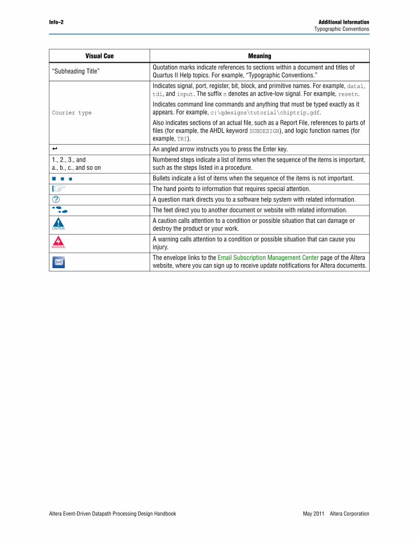
Info–2 Additional InformationTypographic Conventions
“Subheading Title” Quotation marks indicate references to sections within a document and titles of Quartus II Help topics. For example, “Typographic Conventions.”
Courier type
Indicates signal, port, register, bit, block, and primitive names. For example, data1, tdi, and input. The suffix n denotes an active-low signal. For example, resetn.
Indicates command line commands and anything that must be typed exactly as it appears. For example, c:\qdesigns\tutorial\chiptrip.gdf.
Also indicates sections of an actual file, such as a Report File, references to parts of files (for example, the AHDL keyword SUBDESIGN), and logic function names (for example, TRI).
r An angled arrow instructs you to press the Enter key.
1., 2., 3., anda., b., c., and so on
Numbered steps indicate a list of items when the sequence of the items is important, such as the steps listed in a procedure.
■ ■ ■ Bullets indicate a list of items when the sequence of the items is not important.
1 The hand points to information that requires special attention.
h A question mark directs you to a software help system with related information.
f The feet direct you to another document or website with related information.
c A caution calls attention to a condition or possible situation that can damage or destroy the product or your work.
w A warning calls attention to a condition or possible situation that can cause you injury.
The envelope links to the Email Subscription Management Center page of the Altera website, where you can sign up to receive update notifications for Altera documents.
Visual Cue Meaning
Altera Event-Driven Datapath Processing Design Handbook May 2011 Altera Corporation