alsuji, and - nasa · less than some critical value. a reynolds number which is less than 2300 ......
TRANSCRIPT

ENTRY LENGTH FOR THE ROCKET METEOROLOGICAL RADIATION SHIELD
by Forrest L. Stuffunson, Sudiq Alsuji, and Ronald Fuzzio
Prepared by I .
UNIVERSITY OF UTAH Salt Lake City, Utah I '
for
N A T I O N A L A E R O N A U T I C S A N D SPACE A D M I N I S T R A T I O N W A S H I N G T O N , D . C. OCTOBER 1 9 6 8
https://ntrs.nasa.gov/search.jsp?R=19680027058 2018-07-24T13:38:21+00:00Z

TECH LIBRARY KAFB, NM
J"
ENTRY LENGTH FOR THE ROCKET METEOROLOGICAL
RADIATION SHIELD
GJ F - 1 By For ies t L>.,Staffanson, Sadiq Alsaji,>,
and Ronald Fazzio "
Distribution of this report is provided in the interest of information exchange. Responsibility for the contents resides in the author o r organization that prepared it.
Prepared under Grant No. N JiNW33" UTAH &+&> J
Salt Lake City, Utah
for
NATIONAL AERONAUTICS AND SPACE ADMINISTRATION
For sale by the Clearinghouse for Federal Scierttific and Technical Information Springfield, Virginia 22151 - CFSTl price $3.00


ABSTRACT
A d e r i v a t i o n i s p resen ted fo r t he t he rma l en t ry l eng th wh ich
de termines the depth wi th in a t u b u l a r r a d i a t i o n s h i e l d t h a t a temper-
a t u r e s e n s o r may be p l aced w i thou t i ncu r r ing convec t ive hea t t r ans fe r
between the shield and sensor. Data are presented as a f u n c t i o n of
s h i e l d d i a m e t e r , a l t i t u d e , and sensor viewing angle. It i s concluded
t h a t r a d i a t i o n s h i e l d s o f t h e d i a m e t e r of the 4 - inch meteoro logica l
rocke t w i l l p r o v i d e s i g n i f i c a n t s h i e l d i n g t o 80 km a l t i t u d e and s h i e l d s
of the d iameter o f the l - inch dart t o 60 km.
iii
INTRODUCTION
Meteorological rocketsondes commonly u s e a t h e r m i s t o r as t h e
atmospheric temperature sensing e lement , The thermistor is mounted
i n s u c h a way as t o b e immersed i n t h e a i r forward Qf the sonde as
it descends through the upper atmosphere on a parachute. The low
d e n s i t y o f t h e a i r a t t h e h i g h e r a l t i t u d e s d e c r e a s e s t h e t h e r m o m e t r i c
s e n s i t i v i t y o f t h e t h e r m i s t o r so t h a t r a d i a t i o n e r r o r s become l a r g e .
The accuracy of rad ia t ion cor rec t ion$ for a g i v e n f l i g h t is l i m i t e d
by t h e u n c e r t a i n t y o r v a r i a b i l i t y of the rad ia t ion envi ronment dur ing
t h e f l i g h t . The sugges t ion arises then of a r a d i a t i o n s h i e l d w h i c h ,
i n e f f e c t , r e p l a c e s a l l o r p a r t o f t h e less d e s i r a b l e r a d i a t i o n e n v i -
ronment wi th one which i s less i n t e n s e , more un i fo rm o r p red ic t ab le ,
measurable , o r o therwise permi ts more accu race co r rec t ion of t h e
senso r da t a . Obv ious ly t he e f f ec t o f t he sh i e ld on t h e a i r flow over
t he t he rmis to r must be cons ide red i n o rde r t o ach ieve t he des i r ed
r e s u l t .
Perhaps the s implest approach t o s h i e l d i n g is t h a t o f p l a c i n g
an opaque wal l around the thermistor in such a way as t o maximize t h e
so l id ang le o f t he r ep laced r ad ia t ion env i ronmen t w i thou t i n f luenc ing
t h e t e m p e r a t u r e o f t h e a i r s t r e a m a t t h e t h e r m i s t o r . The a i r temper-
a t u r e a t t h e t h e r m i s t o r s u r f a c e may be inf luenced by the presence o f
t he sh i e ld t h rough hydrodynamic ( acce le ra t ion ) e f f ec t s and t he rma l
(hea t ing ) e f f ec t s i nduced by t h e w a l l o n t h e a i r f low. These e f fec ts
may b e u t i l i z e d t o a d v a n t a g e i n some sh ie lded s enso r concep t s . The
present d i scuss ion , however , will be concerned with the simpler con-
c e p t i n which t h e t h e r m i s t o r i s p l a c e d i n t h e e n t r a n c e r e g i o n of a
cy l ind r i ca l t ube deep enough t o max imize sh i e ld ing bu t no t deep enough
to encounter the thermal boundary layer nor the hydrodynamic boundary
l a y e r e x i s t i n g i n t h e e n t r a n c e r e g i o n o f the tube .
- 2 -
BASIC -EQUATION AND IVPUTS
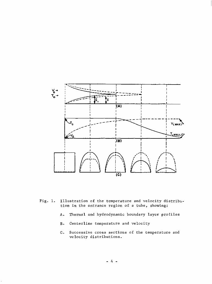
The shapes of the thermal and hydrodynamic boundary layers i n
t h e e n t r a n c e r e g i o n of a tube are exempl i f i ed i n F ig . 1 by those of
laminar cont inuum f low. The temperature and veloci ty dis t r ibut ions
are shown, and as t h e f i g u r e i l l d s t r a t e s , t h e t h i c k n e s s , bT, of the
the rma l boundary l aye r i nc reases f a s t e r t han t ha t , 6, of the 'nydro-
dynamic boundary l ayer . This occurs for f lu ids wi th Prandt l number
less than .un i ty . Th i s be ing t he ca se , t he t he rma l en t ry l eng th Le
i s less than the hydrodynamic entry length Le. LeT i s , t h e r e f o r e ,
t he pa rame te r o f i n t e re s t fo r l oca t ing t he s enso r w i th in t he sh i e ld .
The f low in tubes is always laminar i f the Reynolds number is
less than some c r i t i c a l v a l u e . A Reynolds number which is less than
2300, based on t h e mean v e l o c i t y and tube diameter , is assurance of
l a m i n a r f l o w , I f t h e e n t e r i n g f l u i d i s e s p e c i a l l y free of previous
dis turbances and i f t he t ube wa l l s a r e smoo th , t he c r i t i ca l Reyno lds
number may be t en t imes t h i s va lue o r more. [Sch l i c t ing 1960 .1 It
i s supposed that the a tmosphere encpuntered by the descending sonde
is q u i t e f r e e of s m a l l - s c a l e d i s t u r b a n c e s ( a t l e a s t when compared t o
a i r f lows f rom wind tunnel b lowers) and , therefore , tha t the c r i t i ca l
Reynolds number is l a r g e r t h a n 2300.
1
T
1
Pr = J PC k =(!He)= "momentum d i f f u s i v i t y " 3-=1-=: 6 LeT 0 .72 f o r a i r . " t h e r m a l d i f f u s i v i t y " Le
3
I I I i I
Fig. 1. Illustration of the temperature and velocity distrfbu- tion in the entrance region of a tube, showing:
A . Thermal and hydrodynamic boundary layer profiles
B. Centerline temperature and velocity
C. Successive cross sections of the temperature and velocity distributions.
- 4 -

Even i n t h e e v e n t t h a t t u r b u l e n t f l o w o c c u r s i n t h e t u b e , t h e
boundary layer i s always laminar a t t h e l e a d i n g e d g e a n d c o n t i n u e s
to be laminar downstream to a p o i n t where the loca l Reynolds number
r eaches a c r i t i c a l v a l u e . A t t h e p o i n t o f t r a n s i t i o n t o t u r b u l e n t
f low, the boundary layer becomes much more t h i c k . A t r a n s i t i o n
c r i t e r i o n i n d i c a t i v e o f t h e p o i n t o f commencement o f t u r b u l e n t f l o w
i s suggested by Kays [1966f .
= 360 CRITICAL
Here the Reynolds number i s based on t h e l o c a l c e n t e r l i n e v e l o c i t y
and on t h e momentum th i ckness . The co r re spond ing dep th i n to t he t ube
m i g h t b e c o n s i d e r e d f o r u s e a s t h e e n t r y l e n g t h i f t u r b u l e n c e were
expected to occur . The c a s e s u n d e r d i s c u s s i o n a r e s u f f i c i e n t l y clear
o f t u r b u l e n t c o n d i t i o n s so l amina r cond i t ions a r e assumed f g r t h e re-
mainder o f the d i scuss ion .
2 Sh ie lds o f r egu la r po lygona l c ros s s ec t ion a r e cons ide red
2 E n t r y l e n g t h s f o r r e c t a n g u l a r c y l i n d e r s r a n g e f o r v a r y i n g r a t i o s
of t he i r s ides f rom Le fo r t he squa re (d = s i d e ) t o Le f o r p a r a l l e l p l a t e s (dh = twice t h e s e p a r a t i o n d i s t a n c e )
prtmett, 19623. h
5

i n t h i s d i s c u s s i o n a s h y d r o d y n a m i c a l l y e q u i v a l e n t t o a c i r c u l a r t u b e
hav ing d i ame te r equa l t o t he hydrau l i c d i ame te r d h’
dh = ( c r o s s s e c t i o n a l a r e a ) (per imeter)
Thus t h e e n t r y l e n g t h , L e , o f a s q u a r e c y l i n d e r o f s i d e d i s equa l
t o t h a t o f a c i r c u l a r c y l i n d e r of diameter d.
Kays 119663 approximates the thermal entry length for circular
tubes i n l amina r f l ow as
LeT 2z 0.05 d Re P r = 0.036 d Re
Re = - PVd IJ-
Minor v a r i a t i o n s o c c u r b e t w e e n a u t h o r s p a r t l y d u e t o d i f f e r i n g d e f i -
n i t i o n s f o r t h e commencement of fu l ly deve loped f low. Calcu la t ions
c i t e d by Eckert and Drake [1959] g ive
LeT = 0.0288 d Re
wh ich ag rees exac t ly w i th r e su l t s f rom Sch l i c t ing 119601 fo r t he
hydrodynamic en t ry l ength in a square tube,
Le = 0.04 d Re
6
Le = Le Pr = 0,0288 d R e T
The l a t t e r e x p r e s s i o n i s used i n t h i s pape r fo r t he t he rma l en t ry l eng th
of t he sh i e ld unde r cond i t ions of continuum flow.
A t t h e l o w e r a l t i t u d e s o f i n t e r e s t t h e a i r stream through a
c y l i n d r i c a l s h i e l d b e h a v e s as a continuum. A t h i g h e r a l t i t u d e s t h e
a i r d e n s i t y becomes s u f f i c i e n t l y low t h a t r a r e f a c t i o n e f f e c t s a p p e a r
in the boundary l ayer and the express ions for en t ry l ength must be modified
t o a g r e e w i t h e x p e r i m e n t a l r e s u l t s . A c c o r d i n g t o Schaa-f and Chambre
[1961] deviation from continuum flow i s observed when
0.01 < - M R e ' R e < 1
R e > 1
(5
r e f e r r i n g Knudsen number t o t h e body dimension for R e < 1 and t o
boundary l ayer th ickness for R e > 1. Some e x p e r i m e n t a l i s t s s u g g e s t ,
however, t h a t o n s e t of r a r e f a c t i o n e f f e c t s i n t u b e s is not s o e a s i l y
predicted [Car ley, 1965 1.
Rare f i ed f l ow in t he en t r ance r eg ion of c i r c u l a r c y l i n d e r s was
s t u d i e d a n a l y t i c a l l y by Hanks [1963]. Adapting the resu l t s o f h i s
a n a l y s i s of incompress ib le f low under s l ip condi t ions a t the boundar ies
g ives
LeT = C d R e
7
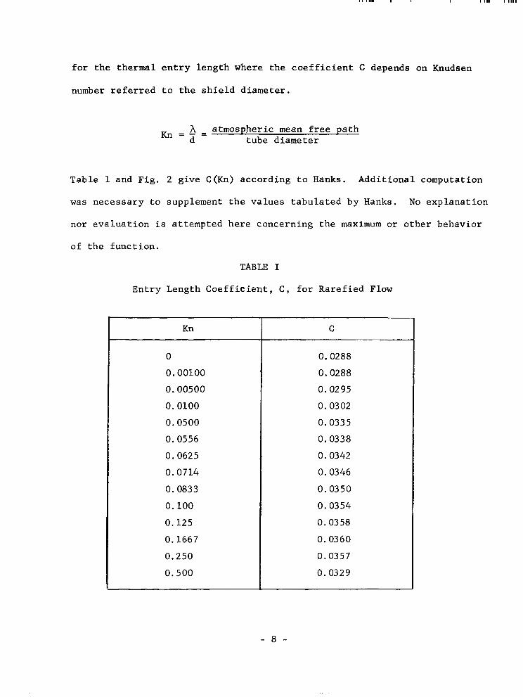
f o r t h e t h e r m a l e n t r y l e n g t h w h e r e t h e c o e f f i c i e n t C depends on Knudsen
number r e f e r r e d t o t h e s h i e l d d i a m e t e r .
K n = - = A atmospheric mean f r e e p a t h d tube diameter
Table 1 and Fig. 2 g ive C (Kn) a c c o r d i n g t o Hanks. Addit ional computat ion
was necessa ry t o supp lemen t t he va lues t abu la t ed by Hanks. No exp lana t ion
no r eva lua t ion i s at tempted here concerning the maximum or o ther behavior
o f t he func t ion .
TABLE I
Ent ry Length Coeff ic ien t , C , f o r R a r e f i e d Flow
Kn
0
0.00100
0.00500
0.0100
0.0500
0.0556
0.0625
0.0714
0.0833
0.100
0.125
0.1667
0.250
0 .500
C
0.0288
0.0288
0.0295
0.0302
0.0335
0.0338
0.0342
0.0346
0.0350
0.0354
0.0358
0.0360
0.0357
0.0329
- 8 -
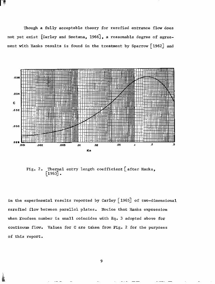
Though a fully acceptable theory for rarefied entrance flow does
not yet exist CCarley and Smetana, 19661, a reasonable degree of agree-
ment with Hanks results is found in the treatment by Sparrow [1962] and
.034
C
.Os2
.030
.OOl .002 .005 .o I .02 .os .I .2 .S
Kn
Fig. 2. Thermal entry length coefficient [after Hanks, [1963] .
in the experimental results reported by Carley [ 19653 of two-dimensional rarefied flow between parallel plates. Noeice that Hanks expression
when Knudsen number is small coincides with Eq. 3 adopted above for
continuum flow. Values for C are taken from Fig. 2 for the purposes
of this report.
9

. .. . . .. . ... "_..
Representative air speeds for rocketsondes are tabulated in
Table I1 and plotted in Fig. 3. The middle air speed profile m/A = 0.02
TABLE I1
Air Speed, 0 (m/sec)
Z (km)
80
75
70
65
6 0
55
50 45
40
0.03
3 00
332
309
23 1
156
108
76
54
37
0.02 -
300
299
258
179 122
86
62 43
32
A
A I R S P E E D (m/secl
0.01
3 00
234
177
12 0
84 6 1 43
34 "
~~
Fig. 3. Representative rocketsonde air speed profiles.
10

i s nomina l ly t ha t o f a ca l cu la t ed two-d imens iona l t r a j ec to ry u s ing
a v a r i a b l e d r a g c o e f f i c i e n t LEddy, 1965 1 t y p i c a l o f the s t anda rd ARCAS
type sonde-parachute sys tem. In addi t ion , a f a s t e r f a l l i n g and a slower
f a l l i n g p a r a c h u t e a r e i n c l u d e d . The two o t h e r a i r s p e e d p r o f i l e s c o r r e -
spond t o a 5 0 p e r c e n t v a r i a t i o n i n parachute mass t o r e f e r e n c e a r e a r a t i o ,
m/A = 0.02 + - 0.01. The high speed curve, m/A = 0.03, approximates the
performance of systems commonly used i n r o c k e t d a r t s and gun probes, while
t h e low speed curve m/A = 0.01 r e p r e s e n t s p o s s i b l e f u t u r e p a r a c h u t e s y s -
t e m s . Thermodynamic p r o p e r t i e s o f t h e a i r r e m o t e from t h e s h i e l d a r e
taken from the U. S. Standard Atmosphere, 1962. P e r t i n e n t v a l u e s a r e
l i s t e d i n T a b l e 111.
*
TABLE I11
Standard Atmosphere
. " . " . ~-
(km)
9 0
85
8 0
75
7 0
65
6 0
55
5 0
45
40
35
3 0
- " "-
cS (m/sec) _ _ . "~
269.44
269 -44
269.44
283 -61
297 -14 310.10
320.61
326.70
329 -80
325.82
317.19
308.30
301.71
3.84
1.53
0.609
0.307
0.164
0.926
0.0532
0.0299
0.0166
0.00850
0.00401
0.0018 1 0 . 0008 01
M c m )
2 -56
1.02
0.407
0.187
0.0928
0.0488
0.0266
0 . 0145
0.00791
0.00413
0.002 Q3
0.000960
0 . 000441
-
11

RESULTS
Shie ld d i ame te r s o f 1 and 1 0 c m were s e l e c t e d f o r a p re l imina ry
t abu la t ion . Tab le s I V and V g i v e t h e values o f t he rma l en t ry l eng th
versus a l t i t u d e f o r t h e two s h i e l d s i z e s and th ree a i r speeds . Values
o f t he a s soc ia t ed d imens ion le s s pa rame te r s R e , M/JZ, Rn, and C a r e
l i s t e d f o r r e f e r e n c e . A l l va lues o f Re a r e w e l l b e l o w t h e c r i t i c a l v a l u e
of 2300 so ca lcu la t ions based on l aminar f low condi t ions are c e r t a i n l y
val id . Curves of Le vs. Z a r e g i v e n i n F i g s . 4 and 5. T
Comparison of Le f o r t h e two s h i e l d s i z e s c l e a r l y shows i t s T 2
dependence on d acco rd ing t o
2 LeT = C d Re = C d pV/p
Large r sh i e ld d i ame te r s , t he re fo re , p rov ide a measure aga ins t the
e v e n t u a l l y o v e r r u l i n g e f f e c t o f t h e e x p o n e n t i a l l y d e c r e a s i n g a i r
d e n s i t y . The l inear dependence on a i r speed i s a l s o s e e n , t h a t i s ,
w i t h i n t h e s m a l l e r e f f e c t s o f t h e r e m a i n i n g f a c t o r s .
These r e s u l t s i n d i c a t e t h a t , a s a l t i t u d e i n c r e a s e s , t h e r m a l
en t ry l eng th dec reases . Fo r a 1 cm d iame te r sh i e ld , t he rma l en t ry
length decreases f rom about 2.7 cm a t 40 km, fo r t he h igh - speed pa ra&
chu te , t o a t r i v i a l 0.17 cm a t 80 km. The co r re spond ing va lues fo r
a 10 cm s h i e l d a r e 2.6 me te r s t o a more a c c e p t a b l e h i g h a l t i t u d e
value of 16 cm. S ince the sensor m u s t remain forward of the entry
- 12 -
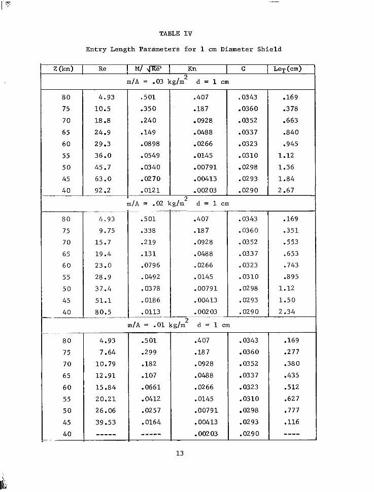
TABLE I V
Entry Length Parameters for 1 cm Diameter Shield
8 0
75
7 0
65
60
55
5 0
45
4 0 ~~ .~ .~. "
. ~~ ~~
8 0
75
7 0
65
6 0
55
5 0
45
40 "
. .
8 0
75
7 0
65
6 0
55
5 0
45
4 0 ~ ~~
4.93
10.5
18.8
24.9
29.3
36.0
45.7
63 .O 92.2
.. . ".
. ~~~ -
4.93
9.75
15.7
19.4
23.0
28.9
37.4
51.1
80.5
~ ~~
4.93
7.64
10.79
12.91
15.84
20.21
26.06
39 -53 ""_ ~~
.501
.350
.240
.149
.08 98
.0549
.0340
.0270
.012 1 --
.407
-187
0928
.048 8
-02 66
.0145
.00791
. 00413
. 002 03 9
m/A = .02 kg/m d = 1 cm L
.501
.338
.219
.131
.0796
.0492
.03 78
.0186
.0113
.. - . .
.407
.187
.092 8
.048 8
.0266
.0145
.00791
.00413
.002 03
m/A = .01 kg/m d = 1 cm L
.501
-299
.182
. 107
.0661
.0412
.0257
-0164
""- ~
.407
.187
.092 8
.048 8
.02 66
.0145
.00791
.00413
.002 03 -
13
.03 43
-036 0
.03 52
.0337
.0323
. 03 1 0
02 98
.02 93
.0290
.03 43
.0360
.0352
.033 7
.0323
.03 1 0
.02 98
.02 93
.0290
.0343
.0360
.0352
.033 7
.0323
.0310
02 98
-02 93
.0290
. 169
-378
.663
.840
.945
1.12
1.36
1.84
2 -67
.169
.351
.553
.653
.743
.895
1.12
1.50
2.34
.169
.277
.380
.435
-512
.627
.777
.116
""
, , ,..,..l..._.""". ._ . . ." .. ... . . . . . ~ ~~ .. -
TABLE V
Entry Length Parameters for 1 0 cm Diameter Shield
80
105.0 75
49.3
922.0 40
630.0 45
457.0 50
360.0 55
293.0 60
249.0 65
188.0 70
80
75
70
65
60
55
50
45
40
80
75
70
65
60
55
50
45
40
m/A = .03 d = 1 0 cm - . -~
.159
.075 9
.018 7 .lll
.0407
.0002 03 .00384
.000413 .00655
.000791 . 01 08
.00145 .0174
.00266 .028 4
.00488 .047 1
.00928
- " ~
m/A = .02 d = 1 0 cm
49.3
.0156 289.0
.02 52 230.0
.0416 194.0
.0693 157.0
. l o 7 97.5
.159
374.0 .009 73
511.0 .00590
805.0 .00358 .. ~ ~
49.3
76.4
108.0
129.0
158 . 0
202 .o 261.0
395.0 ""-
~- "
.0407
.018 7
.00928
.00488
.00256
.00145
.000791
.000413
. 0002 03 ~.
m/A = .01 d = 1 0 cm
.159
.09 45
.05 74
.0339
.02 09
.013 0
.008 12
.00519 """
. . . . . . .
~
.04 07
.018 7
.00928
.00488
. 00256
.00145
.00079 1
.000413
.0002 03 ~
14
-~ ~" .. . 0333
.03 16
.03 05
.02 95
.02 91
.0288
.0288
.0288
.0288 ~ - - . - - . .
~"
.0333
.03 16
.03 05
.02 95
.0291
.0288
.0288
.028 8
.0288 ~~ ~ ~~ ~"
-~~ ~ ~~ - . .
.0333
.03 16
.03 05
.0295
.0291
.0288
.0288
.0288
.0288 ~~~~~ - . "" .
~. .~ "
16.4
33.2
56.5
73.5
85.2
104.0
132.0
181.0
266.0 . ~~ . " - ." . ~
~~~ ~ . "" _" . ~ ~ . - .
16.4
30.8
47.2
57.2
66.9
83.1
107.8
147.0
232.0 - - "
" . ~- . -~
16.4
24.1
32.4
38.1
46.1
58.2
75.0
114.0
~ . . . ~ ~ _ _ "-"
eo
A
T
T
7 5
70
' 6 5
6 0 0
(km) E 5s
50
4 5
4 0
8 0
A
T
T
r s
7 0
' 65
60 D
E 5 s ( k m )
so
4 5
40
Figs. 4 and 5. Thermal entry for 1 cm (upper) and 10 cm (lower) diameter shields.
15
. . - . . . . .
l eng th , necessa ry exposure t o t he ex t e rna l env i ronmen t i nc reases w i th
a l t i t u d e and sh ie ld ing becomes less e f f e c t i v e .
It mus t be kep t i n mind t h a t t h e e n t r y l e n g t h s c a l c u l a t e d a r e
t h e o r e t i c a l maxima f o r t h e l o c a t i o n o f t h e s e n s o r . I n o r d e r t o a v o i d
con tac t w i th t he t he rma l boundary l aye r unde r r ea l cond i t ions , a
sa fe ty margin m u s t be ascer ta ined based on t h e s i z e o f ' t h e s e n s o r , i n -
c l u d i n g t h e c o n d u c t i v e l y n e a r r e g i o n o f i t s suppor t , and on probable
depar tures f rom the idea l condi t ions o f s teady f low. Suppose tha t
a d e q u a t e s h i e l d i n g r e q u i r e s a maximum view ha l f -angle o f 8 and a
r e a s o n a b l e s a f e t y m a r g i n r e q u i r e s t h e s e n s o r t o b e p l a c e d a t me < LeT;
then the sensor depth S i s l i m i t e d by
T
where 8 i s i l l u s t r a t e d i n F i g . 6. It f o l l o w s t h a t
d le^ > 2a t a n e
which implies a minimum sh ie ld d i ame te r
On the o ther hand , g iven a sh i e ld d i ame te r d , a spec i f i ed v i ew ha l f ang le
8, and a s a f e t y f a c t o r a, t h e minimum e n t r y l e n g t h i s defined by
- 16 -
Fig . 6 . View h a l f - a n g l e 8 of a s enso r p l aced a t dep th S i n s h i e l d of diameter d.
Table VI1 l i s t s va lues of (.% for s e l e c t e d v a l u e s of d, a, and 8.
Table V I l i s t s en t ry l eng ths co r re spond ing t o t hese d i ame te r s ove r
t h e a l t i t u d e r a n g e 40-80 km using the nominal (m/A = 0.02) parachute
speeds. Thus, the maximum a l t i t u d e a s s o c i a t e d w i t h a given set of
v a l u e s d ' , e ' , and a' i s t h a t a l t i t u d e i n T a b l e V I co r re spond ing t o
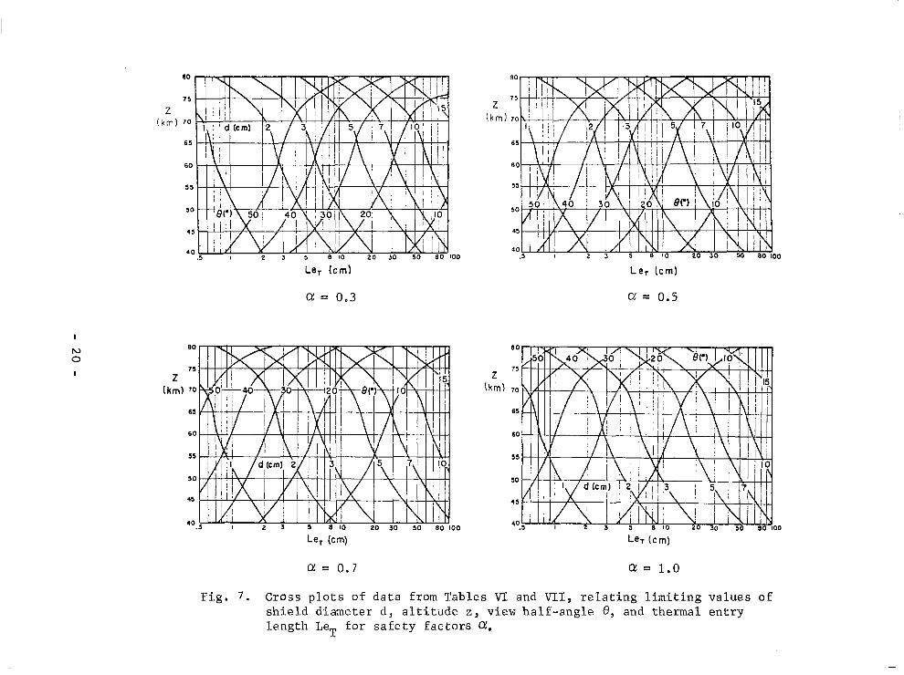
LeT = (.e2 and d = d' . Cross p l o t s of t he two t a b l e s are g i v e n i n
Fig. 7.
- 17 -
d (cm>
z (km)
80
75
70
65
60
55
50
45
40
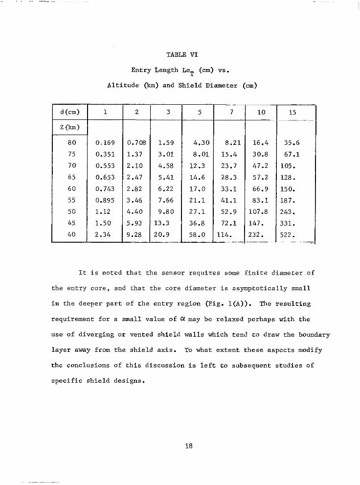
TABLE V I
Entry Length Le (cm) vs.
A l t i t u d e (km) and Shield Diameter (cm)
T
1
0.169
0.351
0.553
0.653
0.743
0.895
1.12
1.50
2.34
2
0.708
1.37
2.10
2.47
2.82
3.46
4.40
5.93
9.28
3
1.59
3.01
4.58
5.41
6.22
7.66
9.80
13.3
20.9 ~
5
4.30
8.01
12.3
14.6
17.0
2 1 . 1
27.1
36.8
58.0 "
7
8.21
15.4
23.7
28.3
33.1
41.1
52.9
72.1
114. -~ . "
1 0
16.4
30.8
47.2
57.2
66.9
83.1
107.8
147.
232. ~. "" -
15 -. ~" ~~
35.6
67.1
105.
128.
15 0.
187.
243.
331.
522. -~ _" . -
It i s n o t e d t h a t t h e s e n s o r r e q u i r e s some f in i t e d i ame te r o f
t h e e n t r y c o r e , and tha t t he co re d i ame te r i s a sympto t i ca l ly small
i n t h e d e e p e r p a r t o f t h e e n t r y r e g i o n ( F i g . l ( A ) ) . The r e s u l t i n g
requi rement for a small va lue o f Q may be r e l axed pe rhaps w i th t he
use of diverging or vented shield wal ls which tend to draw the boundary
l a y e r away from t h e s h i e l d a x i s . To what e x t e n t t h e s e a s p e c t s m o d i f y
t h e c o n c l u s i o n s o f t h i s d i s c u s s i o n i s l e f t t o s u b s e q u e n t s t u d i e s o f
s p e c i f i c s h i e l d d e s i g n s .
18
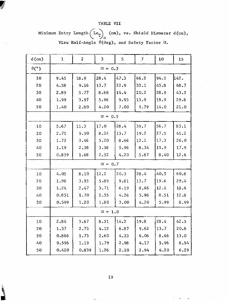
TABLE VI1
Minimum Entry Length (.e.) (cm) , vs. Shield Diameter d(cm), 0
d (cm)
1
10
20
30
40
50 P
10
20
30
40
50 ~ .~
1 0
20
30
40
50
~
1 0
20
30
40
50
V i e w Half-Angle @(deg) , and Safety Factor Q.
1 2 3 5 7 15 10 1 Q: = 0.3
9.45
4.58
2.89
1.99
1.40
18.9
9 -16
5.77
3.97
2.80
1.19 2.38
0.839
4.05
1.96
1.24
0.851
0.599
2.84
1.37
0.866
0.596
0.420
8.10
3.93
2.47
1.70
1.20
5.67
2.75
1.73
1.19
0.839
28.4
13.7
8.66
5.96
4.20
Q: = 0.5
47.3
22.9
14.4
9.93
7.00
56.2
29.8 19.9 13.9
43.3 28.9 20.2
68.7 45.8 32.1
142. 94.5
9.79 14.0 21.0
17.0
8 .24
5.20
3.58
2.52
28.4
8.40 5.87 4.20
11.9 8.34 5.96
17.3 12.1 8.66
27.5 19.2 13.7
56.7 39.7 85 .1
41.2
26.0
17.9
12.6
Q: = 0.7
1.80 3.00
Q: = 1.0
8.51
4.12
2.60
1.79
1.26
8.66
4.20
2.98
28.4
13.7
8.66
5.96
4.20
60.8
29.4
18.6
12.8
8.99
42.5
20.6
13 .O
8.94
6.29
19
a = 0.3
I
0 N
I
BO
Z 75
(km) 70
65
60
55
50
45
40
a = 0.7 a: = 1.0
Fi.g. 7 . Cross p l . o t s of data from Tables VT and VTI, r e l a t i n g l i m i t i n g v a l u e s o f sh ie ld d iameter d , a l t i t u d e z, view half-angle 8 , and thermal entry length LeT f o r s a f e t y f a c t o r s a.
CONCLUSION
Data are presented which re la te the t he rma l en t ry l eng th o f a
c y l i n d r i c a l t u b e t o i t s d iameter and a l t i tude , based on Hanks ' ana lys i s
o f r a r e f i ed i ncompress ib l e f l ow and on nomina l a i r speed p ro f i l e s o f
rocke t meteoro logica l parachute sys tems. Tabula ted da ta and curves
f u r t h e r r e l a t e t h e r a d i a t i o n s h i e l d d i a m e t e r , s e n s o r v i e w a n g l e , a n d
s e n s o r s h i e l d d e p t h r e l a t i v e t o e n t r y l e n g t h . T h u s , maximum a l t i t u d e s
a r e c a l c u l a b l e f o r g i v e n s p e c i f i c a t i o n s o f s h i e l d s i z e a n d v i e w f a c t o r .
I n o r d e r t o a v o i d t h e t h e r m a l b o u n d a r y l a y e r i n s i d e a c y l i n d r i -
c a l r a d i a t i o n s h i e l d , t h e a i r temperature sensing e lement must be
placed forward of t he t he rma l en t ry l eng th . The rma l en t ry l eng th
d e c r e a s e s w i t h a l t i t u d e so t h a t t h e s e n s o r ' s e x p o s u r e t o e x t e r n a l
r a d i a t i o n m u s t i n c r e a s e f o r o p e r a t i o n a t h i g h e r a l t i t u d e s (where s h i e l d -
i n g i s most needed). On the o the r hand , i nc reased sh i e ld d i ame te r s i n -
c rease thermal en t ry l ength and a l low deeper p lacement o f the sensor
f o r g r e a t e r s h i e l d i n g . Though boundary l aye r t echn iques i n t he sh i e ld
conceivably could modify these conclusions, it i s e x p e c t e d t h a t s h i e l d
d imens ions o f the s ize o f convent iona l four - inch meteoro logica l rocke t
nose cones pe rmi t sh i e ld ing t o abou t 80 km a l t i t u d e , and o f t he s i ze
of one- inch dar t s t o about 60 km. This presumes a p r a c t i c a l maximum
v iew ha l f ang le o f abou t 30' and a s a f e t y f a c t o r o f a b o u t 0.5.
- 21 -

LIST OF SYMBOLS
A
C
CP
cS
d
dh
k
‘n
Le
LeT
M
m
Re
S
P r
V
2
a
6
A
P
P
e
parachu te r e f e rence a r ea
e n t r y l e n g t h f a c t o r
s p e c i f i c h e a t o f a i r a t c o n s t a n t p r e s s u r e
speed of sound
sh ie ld d i ame te r
hydrau l i c d i ame te r
t h e r m a l c o n d u c t i v i t y o f t h e a i r
Knudsen number
hydrodynamic entry length
t h e r m a l e n t r y l e n g t h
Mach number
mass of parachute system
Reynolds number
s e n s o r d e p t h i n t o s h i e l d
P r a n d t l number
a i r speed
g e o m e t r i c a l t i t u d e
equa l s S /LeT , s a fe ty f ac to r
hydrodynamic boundary layer thickness
thermal boundary l ayer th ickness
mean f r e e p a t h
a i r d e n s i t y
c o e f f i c i e n t o f v i s c o s i t y
ha l f angle o f sensor v iew
- 22 -

REFEWNCES
Carley, C. T. Jr., "Rarefied Gas Flow in a Short Tube," Ph .D. Thesis,
North Carolina State University, Raleigh, North Carolina,
1964.
Carley, C. T. Jr., and F. 0. Smetana, "Experiments on Transition Regime
Flow Through a Short Tube with a Bellmouth Entry," J. Amer.
Inst. Astronautics &Aeronautics, Vol. 4, No. 1, January,
1966, p. 47.
"
Eddy, Amos, C. E. Duchon, F. M. Haase, D. R. Haragan, "Determination of
Winds from Meteorological Rocketsondes," Report No. 2,
under Contract DA-23-072-AMC-1564, Atmospheric Science
Group, College of Engineering, University of Texas, Austin,
Texas, November,l965.
Eckert, E. R. G., and Robert M. Drake, Jr., Heat and Mass Transfer, "- Second Edition, McGraw-Hill Book Company, New York,
June, 1962, p. 154.
Hanks, R. W., "Velocity Profile Development in the Entrance Region of
a Right Circular Cylinder with Slip at the Walls," - The
Physics - of Fluids, Vol. 6, No. 11, November, 1963, p. 1645.
Hartmett, J. P., G. 6. Y. Koh, and S . T. McComas, Transacttons of the
American Society of Mechanical Engineers, Vol. 84, 1962, pp. 82-88.
Kays, W. M., Convective Heat and Mass Transfer, McGraw-Hill Book
Company, New York, 1966, pp. 125-144.
23

Schaaf , S . A . and P. L. Chambre, Flow o f Ra re f i ed Gases , P r ince ton
U n i v e r s i t y P r e s s , New Jersey, 1961, p . 5.
S c h l i c t i n g , Hermann, Boundary Layer " Theory , Four th Edi t ion , McGraw-Hill
Book Company, New York, 1960, pp. 376, 1 7 1 .
Sparrow, E. M . , T. S . Lundgren, and S . H . L in , "S l ip F low in the Ent rance
Region o f a Pa ra l l e l P l a t e Channe l , " P roceed ings " of 1962
Hea t and T rans fe r F lu ids Mechan ics In s t i t u t e , S t an fo rd
University Press, 1962, pp. 223-238.
"
- 24 - NASA-Langley, 1968 - 14