alstom - p&c -pow relay rph2@o&m manual
TRANSCRIPT

Point-on-Wave Controller Series RPH2
Service Manual
58.020.034 E
ABCd

Page 1/73ALSTOM Austria AG, Linz Issue 2 58.020.034 E
Compiled: Approved: File code:1998-06-08 1998-06-08TBEV2/ U.Samitz TEV/ R.Coccioni RPHDOC_E.DOC
RPH2 Service ManualCONTENTS
1. IN GENERAL 6
1.1. Handling of electronic equipment 6
1.2. Unpacking 6
1.3. Storage 6
1.4. Installation 6
1.5. Technical data 7
2. INTRODUCTION 8
2.1. Using the handbook 8
2.2. Models available, Assembly 8
2.3. Additional modules 82.3.1. Signal module: Option S 82.3.2. Current measurement module: Option I 92.3.3. Analogue module: Option A 9
2.3.3.1 Option A0 92.3.3.2 Option A1 102.3.3.3 Option A3 102.3.3.4 List of available models 10
2.4. Elements on the front of the device 102.4.1. Graphic display 10
2.4.1.1 Setting Contrast of LC-Display 102.4.2. Key-operated switch 11
2.4.2.1 Position "OFF" 112.4.2.2 Position "OPERATION" 11
2.4.3. LED indicators 112.4.3.1.LED "READY" (green) 112.4.3.2.LED 1 to 7 (red) 11
2.4.4. Keys 122.4.5. Serial interface 12
2.5. Menu system 122.5.1. Menu structure 14
3. APPLICATION NOTES 16
3.1. General Description of the Functions 163.1.1. Synchronized switching 16
3.1.1.1 Closing 163.1.1.2 Opening 17

Page 2Issue 2 58.020.034 E ALSTOM Austria AG, Linz1998-06
3.1.2. Circuit breaker 173.1.3. RPH2 structure 173.1.4. Function of the RPH2 18
3.1.4.1 Energizing of an inductive load in the voltage maximum 183.1.4.2 Breaking of an inductive current 193.1.4.3 Switching program 20
3.2. Switching of Transformers and Reactors 203.2.1. Closing 21
3.2.1.1 Networks with grounded Neutral 213.2.1.2 Networks with isolated Neutral 21
3.2.2. Opening 213.2.3. Data on circuit breaker required 21
3.2.3.1 Closing 213.2.3.2 Opening 22
3.2.4. Necessary Switching Time Accuracy 22
3.3. Switching of Reactor Groups 223.3.1. Closing 22
3.3.1.1 Networks with grounded Neutral 223.3.1.2 Networks with isolated Neutral 22
3.3.2. Opening 223.3.3. Data on circuit breaker required 22
3.3.3.1 Closing 233.3.3.2 Opening 23
3.3.4. Necessary Switching Time Accuracy 23
3.4. Switching of unloaded Capacitors 233.4.1. Closing 23
3.4.1.1 Networks with grounded Neutral 233.4.1.2.Networks with isolated Neutral 23
3.4.2. Opening 243.4.3. Data on circuit breaker required 243.4.4 Necessary Switching Time Accuracy 27
3.5 Switching (closing) of uncharged Lines 28
4 FUNCTIONS OF THE ADDITIONAL MODULES 29
4.1 Signal Module: Option S 294.1.1 Alarm outputs 294.1.2 Opto coupler inputs 29
4.1.2.1 Measuring the operating time 294.1.2.2 Remote reset 314.1.2.3 Real time clock synchronization 31
4.2 Analogue Module: Option A 314.2.1 Control Voltage Compensation 324.2.2 Temperature Compensation 334.2.3 Hydraulic Pressure Compensation 354.2.4 Specifications for the external sensors 374.2.5 Adaptive Control 37
4.3 Current Module Option I 38

Page 3ALSTOM Austria AG, Linz Issue 2 58.020.034 E
1998-06
5 RPH2 MENUE SYSTEM 39
5.1 System data 395.1.1 Password 395.1.2 System Frequency 395.1.3 Control Voltage 405.1.4 Rated Pressure 405.1.5 Switching Program 40
5.1.5.1 User Program 415.1.6 Function Channel 1 425.1.7 Language 425.1.8 Time / Date 425.1.9 New Password 425.1.10 Selftest Start 435.1.11 Selftest Interval 43
5.2 CB Data 445.2.1 Operating Time CH1 445.2.2 Operating Time CH2 445.2.3 Arcing Time CH1 445.2.4 Arcing Time CH2 455.2.5 Auxiliary Timeshift CH1 455.2.6 Auxiliary Timeshift CH2 455.2.7 Adaptive Control 45
5.2.7.1 Weighting Factor 465.2.7.2 Adaptive Times CH1 465.2.7.3 Adaptive Times CH2 465.2.7.4 Reset Adaptive Times 46
5.2.8 Compensation 465.2.9 kU1 Voltage CH1 465.2.10 kP1 Pressure CH1 475.2.11 Temperature Compensation CH1 475.2.12 Table Temp. CH1 47
5.2.12.1 Delta_t xx°C 475.2.13 kU2 Voltage CH2 485.2.14 kP2 Pressure CH2 485.2.15 Temperature Compensation CH2 485.2.16 Table Temp. CH1 48
5.2.16.1 Delta_t xx°C 48
5.3 Analogue Data 485.3.1 Thresholds 48
5.3.1.1 Current max. 485.3.1.2 Control Voltage max. 495.3.1.3 Control Voltage min. 495.3.1.4 Temperature max. 495.3.1.5 Temperature min. 505.3.1.6 Pressure max. 505.3.1.7 Pressure min. 50
5.3.2 CT Rated Current prim 515.3.3 CT Rated Current sec 515.3.4 Actual Control Voltage 525.3.5 Temperature 52
5.3.5.1 Value at 4 mA 525.3.5.2 Value at 20 mA 53

Page 4Issue 2 58.020.034 E ALSTOM Austria AG, Linz1998-06
5.3.6 Pressure 535.3.6.1 Value at 4 mA 535.3.6.2 Value at 20 mA 54
5.4 Alarms 545.4.1 Reset Obligatory 545.4.2 Lock-Out 555.4.3 Alarm List 55
5.4.3.1 Lock-out 565.4.3.2 Frequency min 565.4.3.3 Frequency max. 565.4.3.4 Current max. (peak) 575.4.3.5 Reference Voltage Failure 575.4.3.6 RTC Impulse Failure 575.4.3.7 Neutral intermediate 575.4.3.8 Neutral grounded 575.4.3.9 Neutral isolated 575.4.3.10 Selftest ERROR 575.4.3.11 Selftest CH1 ERROR 575.4.3.12 Selftest CH2 ERROR 585.4.3.13 Command Time CH1 min 585.4.3.14 Command Time CH2 min 585.4.3.15 Operating Time min 585.4.3.16 Operating Time max. 585.4.3.17 Drive mech. Failure 595.4.3.18 Archive Full 595.4.3.19 Archive Failure 595.4.3.20 Control Voltage min 595.4.3.21 Control Voltage max. 595.4.3.22 Temperature min 595.4.3.23 Temperature max. 605.4.3.24 Temp. Transducer Fault 605.4.3.25 Pressure min 605.4.3.26 Pressure max. 605.4.3.27 Press. Transducer Fault 60
5.5 Measurement 605.5.1 Current Graphs 605.5.2 Measured Times 61
5.5.2.1 Command OUT 615.5.2.2 CB Signal received 615.5.2.3 Calculated Operating Time 625.5.2.4 Measured Operating Time 62
5.5.3 Frequency 625.5.4 Current (RMS) 635.5.5 Control Voltage 635.5.6 Actual Temperature 635.5.7 Temperature for Compensation 645.5.8 Additional Operating Times 64
5.5.8.1 Voltage CH1 645.5.8.2 Voltage CH2 645.5.8.3 Temperature CH1 655.5.8.4 Temperature CH2 655.5.8.5 Pressure CH1 655.5.8.6 Pressure CH2 65

Page 5ALSTOM Austria AG, Linz Issue 2 58.020.034 E
1998-06
5.5.9 Pressure (L1/L2/L3) 665.5.10 Pressure (L1) 66
5.6 Auxiliary functions 665.6.1 Alarm Input 665.6.2 Alarm Output 675.6.3 Error Type 67
5.7 Switching archive 67
6 COMMISSIONING 68
6.1 Commissioning preliminaries 686.1.1 Settings 68
6.1.1.1 Factory Settings 686.1.1.2 Necessary Settings 68
6.1.2 Inspection 696.1.3 First operation 70

Page 6Issue 2 58.020.034 E ALSTOM Austria AG, Linz1998-06
1. IN GENERAL
1.1. Handling of electronic equipment
A person can cause an electronic potential of many thousands of volts.When this potential is discharged into appliances with semiconductor components,serious damage can occur which is not immediately evident, but can still impairoperational reliability.
The electronic switching circuit of the RPH2 Point-on-Wave Controller from ALSTOMAustria AG, Linz meets all the requirements concerning electromagnetic compatibilityin accordance with the EN 50 081-1/1992 and EN 50 082-2/1995.
Care is necessary only if the plug-in unit is pulled out of the casing. Take care not totouch the plug contact on the back! For storing and transporting loose plug-in units, werecommend a conductive fail packaging.
As soon as the plug-in unit is properly installed in the casing, no safety measures arenecessary at all.
1.2. Unpacking
Despite the general robust construction of the Point-on-Wave Controller, it must behandled with care before installation. Before accepting the Point-on-Wave Controller itshould be checked for damage which could have originated during transportation. Ifyou have cause for complaint, please refer to the transport company and notify aperson responsible at ALSTOM.
1.3. Storage
If the Point-on-Wave Controller is not to be installed immediately upon receipt, itshould be stored in a place which is free of dust and moisture, in its original packaging.If a moisture-absorption bag is in the packaging, leave it as it is. The effectiveness ofthe drying agent is impaired if the non-protected bag is subjected to the surroundingconditions.Before the Point-on-Wave Controller is placed in the box again, warm the drying bagslightly in order to regenerate the drying agent.
Storage temperature: -40 °C to +70 °C
1.4. Installation
The RPH2 Point-on-Wave Controller can either be installed in a switchboard or asuitable frame with the provided material (panel cut-out see diagram 58.001.115), or aspecial fitting is available for wall mounting (see diagram 58.001.116).

Page 7ALSTOM Austria AG, Linz Issue 2 58.020.034 E
1998-06
We suggest the control room or the relays room as the most favourable installationsite. Installation in a heated outdoor control cubicle is also possible. Installation directlyin the operating mechanism of a circuit breaker is not provided for (please contactALSTOM regarding this).The position should be well lit in order to make inspections easier.
Wiring is carried out according to the wiring diagram which is enclosed with everyPoint-on-Wave Controller. Take care to earth the housing appropriately.
1.5. Technical data
supply voltage Nominal: 48 V - 250 VDC(= CB trip coil voltage): Operative range: 35 V - 300 VDCspecial power supply for 48 V -44 % ANSI-Standard availablepower consumption: < 20 W
reference voltage (L1/N): Nominal: 100/√3 V; 220/√3 V ACOperative range: 15 V -105 VAC; 30 V - 250 VAC
rated frequency: 16 2/3 / 50 / 60 Hz ±10 %power consumption of measuring inputs: < 2 VA
maximum permissible current of CB trip coil: 14.5 A/ phase for 1 sec.minimum command time: 100 mspolarity of command impulse: positiveresolution of time setting: 0.1 msaccuracy of switching times overtemperature range -55 °C to +55 °C ±0.3 ms
current inputs: 1 A and 5 Arated short time current: 100 x In / 1 saccuracy of current measurement ±10% (0.5 In ... 4 In)
measurement control voltage internalinput temperature measurement: 4...20 mA of Pt 100input pressure measurement: 4...20 mA of pressure sensoraccuracy of measurement by RPH2:
control voltage ±3%ambient temperature ±3%hydraulic pressure ±3%
signalling inputs: potential free contacts required(e.g. CB or neutral ground disconnector position,CB aux. contacts, external reset)
indication outputs: potential free contactscontact rating 24-250 V AC/DC ± 25 %,
max. 70 VA/ max. 3 A
communication port: RS 232, DC decoupled
Page 8Issue 2 58.020.034 E ALSTOM Austria AG, Linz1998-06
2. INTRODUCTION
2.1. Using the handbook
This handbook will guide the user through the setting-up procedure for the Point-on-Wave Controller.It explains the additional functions of this appliance, and how they are selected andused. In addition, some examples of its usage are given, the theory behind it examinedand explained, and which circuit breaker and main data are absolutely necessary foroperation.The handbook shows the complete list of all menu points with cross-references to thechapter with the accompanying descriptions. The menu point order for the individualmodules is shown on this list as well.Notes on checking and commissioning are given in the last chapter.
2.2. Models available, Assembly
The RPH2 is available in 2 basic models:• RPH2-1xx: for one switching function (closing or opening alternatively)• RPH2-2xx: for 2 switching functions
channel 1 for closing, channel 2 for opening(only when using the given switching programs)
The 7 alarm LED's are active, however there is only one alarm contact (Alarm 1)available. In addition, there is an alarm contact "Device not ready".
The RPH2 Point-on-Wave Controller is assembled in a modular system. The functioncan be extended through the combination of various modules. Extending the functionat a later date is only possible by the manufacturer.
The casing is a standard 19 inch sub-rack, with half width for one device oralternatively with full width for 2 devices. After removing the 4 external screws of thefront panel, the plug-in unit on the grip rail can be removed from the housing. Safetynotes see 1.1.
2.3. Additional modules
2.3.1. Signal module: Option SThis module offers 6 alarm outputs (alarm 2 to alarm 7) and 6 optoelectronic couplerinputs. Inputs 1-3 serve as circuit breaker monitors via its auxiliary contacts. With thisthe pole operating times can be measured. Resolution 0.5 ms.Input 4 serves as an input for a remote-reset. Inputs 5 and 6 are not in use at present.A further input is used for synchronizing with a radio clock. It can be switched in parallelwith other Point-on-Wave Controllers.

Page 9ALSTOM Austria AG, Linz Issue 2 58.020.034 E
1998-06
2.3.2. Current measurement module: Option IWith this the phase currents during the switching process can be recorded andgraphically displayed. Data from the last 4 switching operations (curves, amplitudes) arestored in a non volatile memory and can be analysed on the display. Primary values areshown after feeding in the current transformer ratios.
2.3.3. Analogue module: Option AIndependent of the breaking system and the kind of operating mechanism, the operatingtimes of a circuit breaker change in dependence on certain service parameters:
With reduced control voltage at the circuit breaker coil there is less energy available tochange the electrical control commands into a mechanical action. The operating timeextends itself. (Valid for all types of operations.)
By altering the hydraulic pressure on hydraulic drives, the energy available to carry outthe switching movement changes.
The ambient temperature is the most complex parameter of influence. The electricalresistance of the trip coils, the oil viscosity and the pressure of the SF6 gas aredependent on the temperature. In addition, changes of length in the driving linkage andthe porcelains occur. All these parameters influence the operating time in different ways.
In the extreme, each of these 3 parameters can alter the operating time by somemilliseconds. The RPH2 with option A is in the position to compensate these operatingtime alterations.There are inputs available for the measurements acquired when measuring the controlvoltage, pressure and temperature for the compensation of pole operating times.
The control voltage is measured directly in the RPH2 at the input terminals for theauxiliary voltage. There are no external measuring devices necessary.For measuring pressure and temperature, external sensors with integrated transducerbanks (2 conductor constructions, auxiliary voltage 24 VDC) and standard output signal(4...20 mA) are necessary. The supply for the transducer bank is effected by the RPH2.Up to 8 RPH2's can be switched in parallel on one temperature sensor. Whenmeasuring pressure, an individual transducer is necessary for each circuit breaker(option A1) or each circuit breaker pole (option A3). The measuring range of themeasuring instruments depends on the requirements and can be simply parameterizedin the RPH2.
Three types of this additional module are available:
2.3.3.1. Option A0Measuring and compensation of control voltage and temperature (for springloadeddrives)

Page 10Issue 2 58.020.034 E ALSTOM Austria AG, Linz1998-06
2.3.3.2. Option A1Same design as 2.3.3.1, however with additional measurement and compensation forhydraulic pressure (for hydraulic drives which have a mutual pressure generation for allthree poles).
2.3.3.3. Option A3Like 2.3.3.2, however for circuit breakers which have pressure generation per pole.
2.3.3.4. List of available models
RPH2-1 RPH2-1S RPH2-1I RPH2-1A0 RPH2-1A1RPH2-2 RPH2-2S RPH2-2I RPH2-2A0 RPH2-2A1
RPH2-1A3 RPH2-1SI RPH2-1SA0 RPH2-1SA1 RPH2-1SA3RPH2-2A3 RPH2-2SI RPH2-2SA0 RPH2-2SA1 RPH2-2SA3
RPH2-1SIA0 RPH2-1SIA1 RPH2-1SIA3RPH2-2SIA0 RPH2-2SIA1 RPH2-2SIA3
2.4. Elements on the front of the device
The device identification is located on the right side of the grip rail. The top line showsthe model variation code and the serial number is located on the line beneath.With any queries or questions please state both numbers.
2.4.1. Graphic displayTo show the adjusted and measured values.The top line shows each active menu point. Underneath four menu lines appear. Thelast line (under the drawn line) is the status line. The feed in or measured values appearhere.The digits which are pressed into the front panel underneath the display indicate thepositions for setting the alarms.
S y s t e m D a t a> P a s s w o r d
S y s t e m F r e q u e n c yC o n t r o l V o l t a g eR a t e d P r e s s u r e
0 0 0 01 2 3 4 5 6 7 8
L 1 L 2 L 3
2.4.1.1 Setting Contrast of LC-DisplayTurn key-operated switch to „OFF“.Press the [Enter] button and hold it.Turn the key-operated switch to „OPERATION“.The contrast changes within its limits from dark to light.When the optimal contrast for your requirements is reached, release the [Enter] button.

Page 11ALSTOM Austria AG, Linz Issue 2 58.020.034 E
1998-06
Note: The whole contrast-range of the display is adjustable. Therefore the displaybecomes nearly transparent or dark respectively for a moment. The selected contrast isstored in a non-volatile memory.
2.4.2. Key-operated switch
2.4.2.1. Position "OFF"The RPH2 is blocked. No switching operation is possible. The green LED "READY" isextinguished and the alarm contact "Device not Ready" (-X6: 12/13) closes.
2.4.2.2. Position "OPERATION"After switching to this position the device carries out an internal test. After the averagingof the analogue measured values (pressure, temperature, control voltage) is completed(it takes approx. 20 sec.) and no failure is present, the device switches to "OPERATION"and the green LED "READY" lights up. The alarm contact "Device not ready" (-X6:12/13) opens.
2.4.3. LED indicators
2.4.3.1.LED "READY" (green)Status FunctionSteady light The device is ready for operation
Dark Key-operated switch in "OFF" positionAveraging of analogue measured values is still not completed (see 1.2) Voltage reference is missing or frequency is not in the permitted range (±10 %)The device has identified an internal failure.
Blinking The password is activated, the device can be parameterized. All functions are active.
2.4.3.2.LED 1 to 7 (red)To show the parameterized alarms. The LED's are assigned to the alarm relays 1 to 7.Next to the LED's is a window in which the user's message texts can be placed. For awithdrawn cassette, the input tag with the texts is inserted from the top behind the front.As insert use a sheet of paper 41 mm x 90 mm.
Status FunctionSteady light An alarm has occurred. The LED remains alight until
the alarm is active (regardless of whether the "Quitt" button has been pressed). As long as the LED is alight, the affiliated output relay is also activated.

Page 12Issue 2 58.020.034 E ALSTOM Austria AG, Linz1998-06
Status FunctionBlinking An alarm has occurred which is marked as „Rest
obligatory“After pressing the "Quitt" button two possibilities arise:1) The LED extinguishes, i.e. the alarm was no
longer active when reseted, the output relay is released.2) The indicator switches over to permanent light, i.e. the alarm is still active, the output relay remains energized.
As long as the LED is alight or blinks, the affiliated output relay is energized.
2.4.4. Keys[Enter] Menu point open / confirm[+] Cursor up / increase value[-] Cursor down / decrease value[Esc] Leave menu point / break-off action[Quitt] Acknowledge alarm / alter current scale (together with [+] or [-])
2.4.5. Serial interfaceTo connect the RPH2 to a computer via a standard interface cable.Pinning of connection cable (Nullmodem Cable):
2.5. Menu system
The user surface is organized in several master menu points, each with linked sub-menu points. For their part, the sub-menus can contain further sub-menus. The lastline (under the drawn line) is the status line. Adjusted or measured values are shownhere.The menu structure depends on the RPH2 configuration, e.g. with a device without acurrent measuring module (option I) menu points are not available which areconnected with his function. There are menu cells which can only be read and otherswhere an alteration to the setting can be carried out.
Changes are only possible after the password has been activated.
After feeding the auxiliary voltage, the first four lines of the master menu (1st plane)appear on the display. Move the menu cursor (black triangle on the left side of the
1 1
PC Serial Port RPH2 Serial Port
25 pin plug 9 pin plug
:
1 1
PC Serial Port RPH2 Serial Port
9 pin plug 9 pin plug
Page 13ALSTOM Austria AG, Linz Issue 2 58.020.034 E
1998-06
display) up and down using the [+] an[-] keys. The first four lines of the 2nd plane areshown after pressing [Enter]. Analogues are also valid for the 3rd plane. The menucursor is moved again using [+] or [-]. The contents of the cells are shown in the statusline. If a value is to be altered, move the menu cursor to the desired plane and line.After pressing [Enter], a blinking cursor appears under the first status line position.Change this position using [+] or [-]. [Enter] moves the cursor right to the next position.
With [Esc] the input mode can be left at any time without storing the changes made.
After feeding in the last position the message
Accept: YES - NOappears in the status line.
The input is confirmed with [Enter]. The new value is stored and the menu cursorappears. [Esc] enables the input procedure to be repeated.
After completing the input, turn the key-operated switch to "OFF" and then to"OPERATION" or start the selftest via the menu. After the selftest the data in thesystem is accepted.The following pages show a list of all the available menu points. The cross-referencesto the chapter with the detailed function description are in the column "Chapt.".The column "Module" shows with which model variation this menu is available.The following coding system applies:
-1 RPH2 with one switching function-2 RPH2 with two switching functionsAx Analogue module in all models with module AA1 Analogue module, e.g. Option 1I Current measuring module Option IS Signal module Option S
Menu points without a particular task are available on all models.
Page 14Issue 2 58.020.034 E ALSTOM Austria AG, Linz1998-06
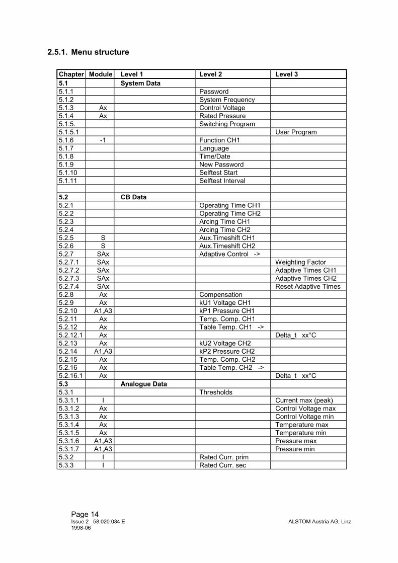
2.5.1. Menu structure
Chapter Module Level 1 Level 2 Level 35.1 System Data5.1.1 Password5.1.2 System Frequency5.1.3 Ax Control Voltage5.1.4 Ax Rated Pressure5.1.5. Switching Program5.1.5.1 User Program5.1.6 -1 Function CH15.1.7 Language5.1.8 Time/Date5.1.9 New Password5.1.10 Selftest Start5.1.11 Selftest Interval
5.2 CB Data5.2.1 Operating Time CH15.2.2 Operating Time CH25.2.3 Arcing Time CH15.2.4 Arcing Time CH25.2.5 S Aux.Timeshift CH15.2.6 S Aux.Timeshift CH25.2.7 SAx Adaptive Control ->5.2.7.1 SAx Weighting Factor5.2.7.2 SAx Adaptive Times CH15.2.7.3 SAx Adaptive Times CH25.2.7.4 SAx Reset Adaptive Times5.2.8 Ax Compensation5.2.9 Ax kU1 Voltage CH15.2.10 A1,A3 kP1 Pressure CH15.2.11 Ax Temp. Comp. CH15.2.12 Ax Table Temp. CH1 ->5.2.12.1 Ax Delta_t xx°C5.2.13 Ax kU2 Voltage CH25.2.14 A1,A3 kP2 Pressure CH25.2.15 Ax Temp. Comp. CH25.2.16 Ax Table Temp. CH2 ->5.2.16.1 Ax Delta_t xx°C5.3 Analogue Data5.3.1 Thresholds5.3.1.1 I Current max (peak)5.3.1.2 Ax Control Voltage max5.3.1.3 Ax Control Voltage min5.3.1.4 Ax Temperature max5.3.1.5 Ax Temperature min5.3.1.6 A1,A3 Pressure max5.3.1.7 A1,A3 Pressure min5.3.2 I Rated Curr. prim5.3.3 I Rated Curr. sec

Page 15ALSTOM Austria AG, Linz Issue 2 58.020.034 E
1998-06
Chapter Module Level 1 Level 2 Level 3Analogue Data (contin.)
5.3.4 Ax Actual Contr. Voltage5.3.5 Ax Temperature5.3.5.1 Ax Value at 4 mA5.3.5.2 Ax Value at 20 mA5.3.6 A1,A3 Pressure5.3.6.1 A1,A3 Value at 4 mA5.3.6.2 A1,A3 Value at 20 mA5.4 Alarms5.4.1 Reset obligatory5.4.2 Lock-out5.4.3 Alarm List5.4.3.1 Lock-out5.4.3.2 Frequency min5.4.3.3 Frequency max5.4.3.4 I Current max (peak)5.4.3.5 Ref. Voltage Failure5.4.3.6 S RTC Impulse Failure5.4.3.7 Neutral intermediate5.4.3.8 Neutral grounded5.4.3.9 Neutral isolated5.4.3.10 Selftest ERROR5.4.3.11 Selftest CH1 ERROR5.4.3.12 -2 Selftest CH2 ERROR5.4.3.13 Command Time CH1 min5.4.3.14 -2 Command Time CH2 min5.4.3.15 S Operating Time min5.4.3.16 S Operating Time max5.4.3.17 S Drive Mech. Failure5.4.3.18 Archive Full5.4.3.19 Archive Failure5.4.3.20 Ax Control Voltage min5.4.3.21 Ax Control Voltage max5.4.3.22 Ax Temperature min5.4.3.23 Ax Temperature max5.4.3.24 Ax Temp. Transd. Fault5.4.3.25 A1,A3 Pressure min5.4.2.26 A1,A3 Pressure max5.4.3.27 A1,A3 Pressure Transd. Fault5.5 Measurement5.5.1 I Current Graphs5.5.2 Measured Times5.5.2.1 Command OUT5.5.2.2 S CB Signal received5.5.2.3 Ax Calculated Op. Time5.5.2.4 S Measured Op. Time5.5.3 Frequency5.5.4 I Current (RMS)5.5.5 Ax Control Voltage

Page 16Issue 2 58.020.034 E ALSTOM Austria AG, Linz1998-06
Chapter Module Level 1 Level 2 Level 3Measurement (contin.)
5.5.6 Ax Temperature5.5.7 Ax Temperature f. Comp5.5.8 Ax Additional Op. Times5.5.8.1 Ax Voltage CH15.5.8.2 Ax Voltage CH 25.5.8.3 Ax Temperature CH15.5.8.4 Ax Temperature CH25.5.8.5 A1,A3 Pressure CH15.5.8.6 A1,A3 Pressure CH25.5.9 A3 Pressure (L1/L2/L3)5.5.10 A1 Pressure (L1)5.6 Aux. Functions5.6.1 S Alarm Output5.6.2 S Alarm Input5.6.3 Error Type5.7 Switching Archive
3. APPLICATION NOTES
3.1. General Description of the Functions
The RPH2 Point-on-Wave Controller is a three-phase control device for circuitbreakers with single pole drives. It can be used for both the energizing and de-energizing of high voltage devices.
3.1.1. Synchronized switching
3.1.1.1. ClosingEnergizing of transformers, reactors and capacitors is normally effected three-pole - forall 3 phases simultaneously. In doing this the point on wave is left up to chance. Ifclosing is carried out in this manner, high inrush currents with high DC components areunavoidable. When energizing capacitors additional high switching surges can occur.The results are unwanted operation of protection devices and repercussions onmachines and network.
The inrush currents and switching surges can be reduced to an acceptable rate byinstalling closing resistors at the circuit breaker. The costs for such closing resistors arevery high, due to the mechanical expenditure. Besides, the necessarily high energeticabsorbtivity of the resistor material sets relatively restricted limits of practicability.
By selecting a suitable switching time the physical causes of these high inrush currentscan be counteracted. This possibility is effected through synchronized switching with theRPH2. This enables the three poles of a circuit breaker to be controlled independently.

Page 17ALSTOM Austria AG, Linz Issue 2 58.020.034 E
1998-06
3.1.1.2. OpeningThe de-energizing of shunt reactors is a critical process liable to generate re-ignitionsbetween circuit breaker contacts. This means very high stress for the insulation of boththe shunt reactor and the circuit breaker.
If the contact separation takes place a sufficient amount of time before the current zerocrossing through suitable circuit breaker control, to ensure a gap capable ofwithstanding the transient recovery voltage at interruption.
3.1.2. Circuit breakerThe mechanical closing time of the circuit breaker is defined as the time between theelectrical command to the operating coil and touching of the main contacts.
On the other hand, the opening time is the time between the electrical command and theseparation of the main contacts. The operating times of circuit breakers, independent ofthe breaking system and the type of operating mechanism, changes in dependence oncertain service parameters:
• With reduced control voltage at the operating coil there is less energy available tochange the electrical control commands into a mechanical action. The operatingtime extends itself. (Valid for all types of operating drives.)
• By altering the hydraulic pressure on hydraulic drives, the energy available to carry
out the switching movement changes. • The ambient temperature is the most complex parameter of influence. The electrical
resistance of the operating coils, the oil viscosity and the pressure of the SF6 gasare all dependent on the temperature. Moreover, there is expansion of operatingrods and porcelains. All these parameters influence the operating time in differentways.
In the extreme, each of these 3 parameters can alter the operating time by somemilliseconds. The RPH2 is in the position to compensate these operating time variations.
3.1.3. RPH2 structureThe outstanding features of the RPH2 are:
• Microprocessor control with a switching command time resolution of 0,1 ms. • Large graphic display to show the adjusted and measured values ( in German,
English and French or user defined language) • Easy setting via keypad or PC interface. • Analogue module for measuring control voltage, pressure and temperature, for the
compensation of changes in operating time.

Page 18Issue 2 58.020.034 E ALSTOM Austria AG, Linz1998-06
• Current measuring function for the graphic display of the line currents duringswitching.
• Extensive alarm functions • Two switching functions (CLOSING and OPENING) with one device are possible. • Switching programs with fixed switching times for the most frequent applications. • A free program is available for special user-defined applications (e.g. switching
unloaded lines). • Extensive archive function. The most important data for the last 1000 operations are
stored in a non-volatile memory and are available for diagnostic purposes. • Comfortable PC software for setting and read-out archive data. All data can be
stored and printed out. If the user cannot find sufficiency with the three languagesmentioned previously, then the display can be translated into the user's nationallanguage using PC software.
• Compact housing for flush mounting or wall mounting.
3.1.4. Function of the RPH2The phase-synchronous trigger-signal is taken from the network voltage (phase L1). Thetrigger-signal is based on the voltage-zeros of the reference voltage.The network voltage is also used as a reference for circuit opening. The amount ofphase shift between current and voltage is almost always +90°el. or -90°el. (A deviationof ±1°el. creates a variation of ±0,06 ms of the switching point.)The controller's mode of operation shown below. The diagrams are only single-phasedand shown without transient effects which may possibly occur.
3.1.4.1. Energizing of an inductive load in the voltage maximum (Fig. 1)At any point on wave whatever, the control impulse is given to the RPH2 (1). The nextvoltage zero crossing is the internal synchronizing impulse (2). Depending on the givenoperating time for the respective pole, a time delay t_d is calculated so that currentstarts at the required time (3). Through the unavoidable pre-arcing in the circuit breakerpole the current begins before actually touching the contacts. Contact touching happensat the pre-arcing time after the voltage maximum (optimum switching time). The requiredpre-arcing time t_arc is separately adjustable for all three phases. The two other phasesare controlled in the same (independent) manner.

Page 19ALSTOM Austria AG, Linz Issue 2 58.020.034 E
1998-06
Figure 1
t_arc
t d CB operating time
Systemvoltage
Current
CB-ONcommandto RPH2
Commandby RPH2
CB maincontact
1
2
3
4
timet_arc...pre-arcing time of CBt_d... delay time of RPH2
3.1.4.2. Breaking of an inductive currentAt any point on wave whatever, the control impulse is given to the RPH2 (1). The nextvoltage zero crossing is the internal synchronizing impulse (2). Depending on the givenoperating time for the respective pole, a time delay t_d is calculated so that contactseparation occurs at the required time (3). In the time between contact separation andthe following current zero crossing, the contacts have separated so far that after thecurrent breaking in the zero crossing (4),an adequate contact gap exists to withstand thetransient recovery voltage. The required arcing time t_arc is separately adjustable for allthree phases. The two other phases are controlled in the same (independent) manner.
Figure 2
t_arc
t_d CB operating time
t_arc...arcing time of CBt_d ...delay time of RPH2
Systemvoltage
Current
CB-OFFcommandto RPH2
Commandby RPH2
CB maincontact
1
2
34
time

Page 20Issue 2 58.020.034 E ALSTOM Austria AG, Linz1998-06
Whether the system neutral is grounded or isolated, the RPH2 registers the signalcontacts of the neutral earthingswitch and automatically selects the correct switchingtime.
3.1.4.3. Switching programThe RPH2 already has several preconfigured switching programs for various uses.The treatment of the system neutral of the network is automatically taken intoconsideration.The trigger point for the switching times is the beginning of the period that isdeterminated by the zero crossing of the voltage L1-N (reference voltage). The givendelay times in table 1 are given in milliseconds after the trigger point. They show themoment where current flow begins or ends (point (4) in figures 1 and 2). The RPH2automatically takes pre-arcing and breaking times into account.
The following programs are available:• Transformer (transformer, transformer bank, three-core reactor)• Reactor (reactor group)• Capacitor bank• Free program
The following table is based on a phase sequence of the network ofL1= reference L2= reference - 120° L3= reference - 240°
Table 1: Delay times of the various switching programs.Switching programs Neutral Operation Delay time
L1 L2 L3Transformer GROUNDED CLOSING 5 (4.2) 10 (8.3) 10 (8.3)
OPENING 5 (4.2) 1.7 (1.4) 8.3 (6.9)ISOLATED CLOSING 5 (4.2) 0 0
OPENING 5 (4.2) 10 (8.3) 10 (8.3)Reactor GROUNDED CLOSING 5 (4.2) 1.7 (1.4) 8.3 (6.9)
OPENING 5 (4.2) 1.7 (1.4) 8.3 (6.9)ISOLATED CLOSING 5 (4.2) 0 0
OPENING 5 (4.2) 10 (8.3) 10 (8.3)Capacitor GROUNDED CLOSING 0 6.7 (5.6) 3.3 (2.8)
OPENING 5 (4.2) 1.7 (1.4) 8.3 (6.9)ISOLATED CLOSING 10 (8.3) 5 (4.2) 5 (4.2)
OPENING 5 (4.2) 10 (8.3) 10 (8.3)Values in () for 60 Hz.The free program enables the user to select whatever switching time for both switchingfunctions (if available) and for both types of neutral treatment.
3.2. Switching of Transformers and Reactors
For this switching task select the program "Transformer" in the menu [System Data][Switching Program]. The switching times are specified as seen in table 1.
For transformers with primary windings in delta connection the program for isolatedneutral must be used (short circuit the terminals -X6:8 with -X8:11 of the RPH2).

Page 21ALSTOM Austria AG, Linz Issue 2 58.020.034 E
1998-06
3.2.1. Closing
3.2.1.1. Networks with grounded NeutralCircuit breaker closing takes place in the voltage peak in order to prevent transientprocesses. With earthed-neutral networks the obvious thing to do would be to switchoffset the three phases L1, L2 and L3 in their respective voltage peak, i.e. timewiseeach one about a third of the period. Due to the mutual coupling of the individual phases(via the iron core in three-core transformers or via the low-voltage winding in transformerbanks) this switching sequence did not have the desired effect. The first phase L1 isclosed in the voltage peak (a quarter period after the voltage zero crossing of thereference voltage L1-N). Because the first phase is laid to nominal voltage, the flux inthe relevant core rises also to its nominal value. This flux closes via both the remaining,non-generated cores, to each a half. If closing of the two remaining phases occurs aquarter period after the first, current flow can start immediately and without transientprocess (switching sequence L1-L2+L3).
3.2.1.2. Networks with isolated NeutralWith an isolated neutral, closing of one phase makes no sense. Two phases must beclosed first (L2 and L3) and the obvious thing to do would be to select for the switchingtime the voltage peak of the phase to phase voltage (i.e. zero crossing of the referencevoltage L1-N). Switching on the third phase occurs about a quarter period later, at thepeak of voltage L1 (switching sequence L2+L3-L1).
3.2.2. OpeningFor switching off transformers and three leg reactors with the RPH2, please read point3.3.2 "Switching off Reactor Groups".
3.2.3. Data on circuit breaker requiredThe following data on the circuit breaker are absolutely necessary to operate the RPH2:
The mechanical closing and/or opening operating time of the three circuit breaker poles(see 3.1.2 for definition). Accuracy about ±0,1 ms.
3.2.3.1. ClosingFor closing at the correct time, the pre-arcing time of the breaker at the closing voltage(see table 2) according to the phases and the treatment of the system neutral.
Table 2: Closing Voltage (Un= system voltage (rms.))Phase Neutral Grounded Neutral IsolatedL1 √(2/3)*Un 1.5*√(2/3)*UnL2 ½*√2*Un ½*√2*UnL3 ½*√2*Un ½*√2*Un
If the exact value cannot be obtained from the breaker manufacturer, the optimumclosing time can be determined through switching tests with oscillographicalmeasurements of the inrush currents. For RPH2 with option I, the inrush currents aredirectly shown by the device (curve course and peak value). For the tests it is advisable

Page 22Issue 2 58.020.034 E ALSTOM Austria AG, Linz1998-06
to begin with an assumed pre-arcing time of 3 ms at √(2/3)*Un, 2.5 ms at ½*√2*Un and4.5 ms at 1.5*√(2/3)*Un.
3.2.3.2. OpeningData of the optimum arcing time in order to guarantee a sure current breaking in thenext zero crossing.See 3.3.3 for further information
3.2.4. Necessary Switching Time AccuracyWith regard to the accuracy of the switching time, closing in the voltage peak is not socritical. By closing at 1 ms before or after the peak, the voltage still amounts to 95 % ofthe peak value, at 2 ms at least 81 % (valid for 50 Hz).Therefore an accuracy of ±2 ms at 50 Hz or 60 Hz is sufficient.
See 3.3.4 for opening values
3.3. Switching of Reactor Groups
For this switching task select the program "Reactor" in the menu [System Data][Switching Program]. The switching times are specified as seen in table 1.If the RPH2 is only to be used for opening, then this program can also be used toswitch three core reactors (switching moments are identical to the transformerprogram).
3.3.1. Closing
3.3.1.1. Networks with grounded NeutralClosing takes place in the voltage peak in order to prevent transient processes. Withgrounded neutral networks the three phases L1, L2 and L3 are closed in their respectivevoltage peak, i.e. timewise each one offset about a third of the period, as there is nocoupling between the phases (switching sequence L2-L1-L3).
3.3.1.2. Networks with isolated NeutralClosing runs according to the same principles as in the program for transformers (see3.2.1.2).
3.3.2. OpeningBreaking of small inductive currents, as is with reactors, can lead to high switchingsurges if current chopping or restriking in the circuit breaker occurs.Contact separation should take place a sufficient time before current zero crossing sothat after current breaking the contact gap is great enough to withstand the recoveryvoltage. The switching times given in table 1, indicate the moment of current breaking.The necessary arcing window is taken into account by the RPH2 through the arcingtime.
3.3.3. Data on circuit breaker requiredThe following data on the circuit breaker are absolutely necessary to operate the RPH2:

Page 23ALSTOM Austria AG, Linz Issue 2 58.020.034 E
1998-06
The mechanical closing and/or opening operating time of the three circuit breaker poles(see 3.1.2 for definition). Accuracy about ±0,1 ms.
3.3.3.1. ClosingThe pre-arcing times of the circuit breaker must be known.
• Pre-arcing time of the breaker in the voltage peak: equal value for all three phaseswith grounded neutral or for phase L1 with isolated neutral.
• Pre-arcing time with partial voltage: for phases L2 and L3 with isolated neutral (seetable 2)
3.3.3.2. OpeningThe optimum arcing time input determines the arcing window for a secure currentbreaking, free from restrikes, in the next zero crossing. The value is given by thebreaker manufacturer.
In order not to come into conflict with unavoidable operating time tolerances, contactseparation should begin 1,5 ms after zero crossing at the earliest, i.e. do not select anarcing time of longer than 8,5 ms (6,8 ms at 60 Hz). About a quarter period as arcingtime is regarded as standard time.
3.3.4. Necessary Switching Time AccuracyFor circuit breaker closing, point 3.2.4 applies (standard value ±2 ms).
For circuit breaker opening, the breaker should achieve an operating time accuracyof ±1,5 ms.
3.4. Switching of unloaded Capacitors
For this switching task select the program "Capacitor" in the menu [System Data][Switching Program]. The switching times are specified as seen in table 1.
3.4.1. ClosingHigh inrush currents and high voltage surges can occur with the random switching ofcapacitors, especially if switching takes place in the voltage peak. The effects of parallelswitching of capacitors is particularly serious. Particularly high voltage surges can occur,due to reflections at the end of radial networks.
3.4.1.1. Networks with grounded NeutralClosing takes place in the voltage zero crossing of the related phase-to earth voltage,i.e. all phases offset one third of the period (switching sequence L1-L3-L2).
3.4.1.2. Networks with isolated NeutralAs a unipolar switching makes no sense, two phases are simultaneously closed in thevoltage zero crossing of their phase to phase voltage. The third phase follows a quarterperiod later (switching sequence L2+L3-L1).

Page 24Issue 2 58.020.034 E ALSTOM Austria AG, Linz1998-06
3.4.2. OpeningIn general, breaking of capacitive currents represents no problem for modern circuitbreakers. If the RPH2 is used for the synchronized switching of capacitor banks, thenthe same applies as in 3.3.2, i.e. contact separation in sufficient time before voltage zerocrossing.
3.4.3. Data on circuit breaker requiredThe following data on the circuit breaker are absolutely necessary to operate the RPH2:
The mechanical closing and/or opening operating time of the three poles (see 3.1.2 fordefinition). Accuracy about ±0,1 ms.
In order to achieve the necessary accuracy when closing in the voltage zero crossing,the rate of fall of the withstand voltage (dUd/dt) of the breaker should be greater thanthe rate of change of the gap voltage at voltage zero (dU/dt). Figure 3 shows threepossible cases.
1 The rate of fall of the breakers withstand voltage (dUd/dt) is less than the rate offall of the system voltage (dU/dt). dUd/dt < dU/dt, k<1.The breaker can be used for this application if dUd/dt > 0.8*dU/dt. In this caseplease contact the manufacturer of the breaker for calculation of the pre-arcingtimes.
2 The rate of fall of the breakers withstand voltage (dUd/dt) is equal to the rate offall of the system voltage (dU/dt). dUd/dt = dU/dt, k=1.
3 The rate of fall of the breakers withstand voltage (dUd/dt) is greater than the rateof fall of the system voltage (dU/dt). dUd/dt > dU/dt, k>1.
Figure 3
u 1 2 3
1 interrupter dielectric strength lower than dU/dt of system voltage2 interrupter dielectric strength equal dU/dt of system voltage3 interrupter dielectric strength greater than dU/dt of system voltage
t

Page 25ALSTOM Austria AG, Linz Issue 2 58.020.034 E
1998-06
However, some pre-arcing may be inevitable due to variations in the closing time andthe spread in dielectric withstand. To minimise energizing transients, the closing shouldaim at an instant, td, after the voltage zero (the RPH2 takes this into account through agiven arcing time). If data is not available from the breaker manufacturer, the pre-arcing time can be approximated. Modern breakers have closing contact speeds oftypical 5 m/s and a dielectric strength of more than 20 kV/mm. That results in a fall rate(dUd/dt) of more than 100 kV/ms.
Figure 4 shows the voltage across the open contact gap and the withstand voltage fallwith varying closing times. The arcing time ta is calculated so that the withstandvoltage is approx. the same value as the upper and lower operating time tolerance.
Figure 4
u
T T
ta
Up
t
Ud
voltage across the open contact gap and withstand voltagefall with varying closing time T1±∆T
T1
The RPH2 arcing time setting can be calculated according to the following formulas.Take note of the differing arcing times with isolated neutrals. The calculations must beverified by switching tests.

Page 26Issue 2 58.020.034 E ALSTOM Austria AG, Linz1998-06
Note: The system voltage in the following formulas is related to one interruptingchamber of the circuit breaker, take care in case of breakers with multiple interruptingchambers!The voltage across one interrupting chamber is calculated as follows where "m" is thenumber of interrupting chambers of one pole:
Un... Voltage for one interrupting chamber
The following example demonstrates the calculation for the pre-arcing time for eachpole with various system neutral treatments.
Un = U 1.05m
system
m-1
⋅
U [kV] system voltage (rms) for one interrupting chamber
u'= U [kV] peak value, neutral grounded, for all poles
u'= U [kV] peak value, neutral isolated, for the two
first poles L2 and L3
u'=1.5 U [kV] peak value, neutral isolated, for the last
pole L1
u' [kV/ ms] rateof fall of system voltage
dUdt
[kV/ ms] rate of fall of CB withstand voltage
dUdtdUdt
=
n
n
n
n
d
d
⋅
⋅
⋅ ⋅
= ⋅ ⋅
232
2
23
11000
dUdt
ω
k [p.u.] see figure 3
T [ms] variation of CB closing time
t =sin( T
1000k
[ms] prearcing time set to RPH2
U =sin( T1000
u [kV] prearcing voltage
a
p
∆∆
∆
ω
ω
ω
⋅
⋅⋅
⋅ ⋅
)
)
1000

Page 27ALSTOM Austria AG, Linz Issue 2 58.020.034 E
1998-06
Example:
U 145 [kV] system voltage (rms)u'= 118.4 [kV] peak value, neutral grounded, for all polesu'= 102.5 [kV] peak value, neutral isolated, for the two first poles L2 and L3 u'= 177.6 [kV] peak value, neutral isolated, for the last pole L1
[kV / ms] rate of fall of system voltage, neutral grounded
[kV / ms] rate of fall of system voltage, neutral isolated
(for the two first poles L2 and L3)
[kV / ms] rate of fall of system voltage, neutral i
n =
dUdtdUdt
dUdt
=
=
=
37 2
32 2
558
.
.
. solated
(for the last pole L1)dUdt
= 100 [kV / ms] rate of fall of CB withstand voltage
k = 2.7 [p.u.] neutral grounded, for L1, L2, L3 k = 3.1 [p.u.] neutral isolated, for L2, L3 k = 1.8 [p.u.] neutral isolated, for L1 T = 1 [ms] variation of CB closing timeta = 0.4 [ms] neutral grounded, prearcing time set to RPH2 for all polesta = 0.3 [ms] neutral isolated, prearcing time set to RPH2 for poles L2 and L3ta = 0.5 [ms]
d
∆ ±
neutral isolated, prearcing time set to RPH2 for pole L1
3.4.4 Necessary Switching Time AccuracyCapacitor energizing places the greatest demands on the breaker in reference tooperating time constancy. Every variation from the required switching time leads to ahigher withstand voltage value which causes greater surges and inrush currents.Closing time variation should amount to ± 1 ms at the most. When this accuracycannot be maintained under all conditions, we recommend the use of the analoguemodule option A to correct the operating time influences.
For closing, the switch should reach a operating time accuracy of ± 1,5 ms.

Page 28Issue 2 58.020.034 E ALSTOM Austria AG, Linz1998-06
3.5 Switching (closing) of uncharged Lines
Uncharged high voltage lines are to be fundamentally treated like capacitors. Due tothe inter-phase coupling the switching moments are not the same as for capacitorbanks. The RPH2 can also be used for auto-reclosing of uncompensated linesequipped with inductive potential transformers. During the auto-reclose dead-time thetrapped charges on the line must be fully discharged by the inductive potentialtransformers!
Whether the system neutral is earthed or isolated does not effect the switchingmoments.
The RPH2 must be set to the [User Program] with the following settings (see also5.1.5.1).
For [T_C1 Neutral isolated] and for [T_C1 Neutral grounded] the same values must beset:
50 Hz:L1 = 0 msL2 = 7.3 msL3 = 13.3 ms
60 Hz:L1 = 0 msL2 = 6.1 msL3 = 13.3 ms

Page 29ALSTOM Austria AG, Linz Issue 2 58.020.034 E
1998-06
4 FUNCTIONS OF THE ADDITIONAL MODULES
4.1 Signal Module: Option S
4.1.1 Alarm outputsThe module offers additional outlets (alarm 2 to 7). Each alarm contact correspondswith the associated indicator-LED (LED 2 to 7) at the front. The allocation of the alarmfunctions to the output contacts is user-defined. Many alarm functions can be laid toone output. The procedure is described in chapter 5.
4.1.2 Opto coupler inputsOpto coupler inputs with pre-defined functions are available.
4.1.2.1 Measuring the operating timeThree inputs serve to measure the operating time of the three poles via their auxiliarycontacts. (Resolution 0,5 ms). The circuit breaker auxiliary contacts signalling (contact52a) works with an internal RPH2 voltage (48 VDC), i.e. potential-free contacts arenecessary. The necessary wiring is to be carried out according to the accompanyingwiring diagram.
Figure 5
CB maincontact
CB aux.contact
CB maincontact
CB aux.contact
closing
opening
-∆ t
∆ t
time
To compensate the time shift between the main contacts and the auxiliary contacts ofthe breaker poles, the possibility exists to feed in a compensation time in order tomaintain the operating time as real value on the display and in the archives. Figure 5shows the correlation as an example. If the auxiliary contact closes after the maincontact then the compensation time value. ∆t is negative, if the auxiliary contact opensbefore the main contact then a positive value results. If no possibility exists to measurethe time shift of the auxiliary contacts, this value can also be determined via the RPH2within the time release limits.Conditions:• The pole operating times given by the manufacturer are correctly fed in (see 5.1
and 5.2)
Page 30Issue 2 58.020.034 E ALSTOM Austria AG, Linz1998-06
• The environmental conditions correspond approx. to the conditions when measuringthe pole operating times in the factory. With strong deviations in the environmentalconditions, the pole operating times must be measured again on site.
• The RPH2 compensating function is deactivated (see 5.6).• The circuit breaker can be operated repeatedly without load (with opened busbar
disconnector.
Operate the circuit breaker via the RPH2 with channel 1.
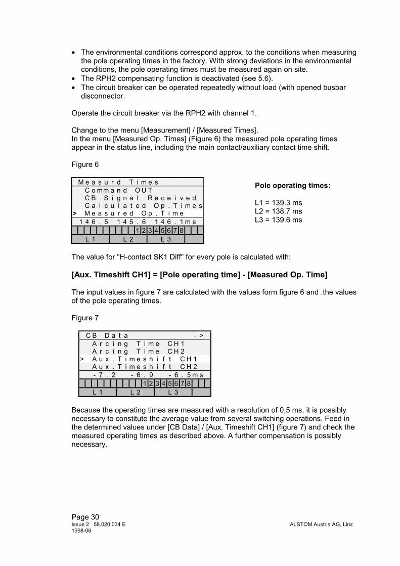
Change to the menu [Measurement] / [Measured Times].In the menu [Measured Op. Times] (Figure 6) the measured pole operating timesappear in the status line, including the main contact/auxiliary contact time shift.
Figure 6
M e a s u r d T i m e sC o mm a n d O U TC B S i g n a l R e c e i v e dC a l c u l a t e d O p . T i m e s
> M e a s u r e d O p . T i m e1 4 6 . 5 1 4 5 . 6 1 4 6 . 1 m s
1 2 3 4 5 6 7 8L 1 L 2 L 3
The value for "H-contact SK1 Diff" for every pole is calculated with:
[Aux. Timeshift CH1] = [Pole operating time] - [Measured Op. Time]
The input values in figure 7 are calculated with the values form figure 6 and .the valuesof the pole operating times.
Figure 7
C B D a t a - >A r c i n g T i m e C H 1A r c i n g T i m e C H 2
> A u x . T i m e s h i f t C H 1A u x . T i m e s h i f t C H 2- 7 . 2 - 6 . 9 - 6 . 5 m s
1 2 3 4 5 6 7 8L 1 L 2 L 3
Because the operating times are measured with a resolution of 0,5 ms, it is possiblynecessary to constitute the average value from several switching operations. Feed inthe determined values under [CB Data] / [Aux. Timeshift CH1] (figure 7) and check themeasured operating times as described above. A further compensation is possiblynecessary.
Pole operating times:
L1 = 139.3 msL2 = 138.7 msL3 = 139.6 ms

Page 31ALSTOM Austria AG, Linz Issue 2 58.020.034 E
1998-06
Check in all cases that the measured operating time corresponds with actual operatingtimes of the circuit breaker. This is essential for using the function of the adaptivecontrol !
For devices with two switching functions (RPH2-2), repeat the procedure for thesecond switching channel too.
4.1.2.2 Remote resetAn input for remote reset is available. A potential-free contact (closer) is necessary ascontrol device. Drive takes place with the RPH2 intern 48 VDC voltage.
4.1.2.3 Real time clock synchronizationA further input is for synchronizing with a radio clock. It can be parallel switched withother synchronized control devices. A potential-free contact is necessary.
4.2 Analogue Module: Option AWith this module the influence of environmental parameters on the pole operating timecan be compensated. External sensors are necessary for pressure and temperaturemeasurement. Control voltage, pressure and temperature are continually measured.The voltage and pressure values are immediately available for the calculation ofcompensation times. The shown vales in the menus [Measured value/Control voltage]and [Measured value/Pressure] are the basic calculating factors.An average value formation is carried out for temperature compensation.Update takes place every two hours. The stored temperature value is compared withthe measured value and the stored temperature is compensated by half the difference(figure 8). In the menu [Measured value/Temperature] the actual measuredtemperature is shown, in the menu [Measured value/Temperature f. Comp.] theaverage is shown which is effective for compensation.
Figure 8
ambient temperature
temperature for compensation

Page 32Issue 2 58.020.034 E ALSTOM Austria AG, Linz1998-06
In the menu [Measured value/Compensation] each of the actual additional times areshown. After the key-operated switch is turned form "OFF" to "OPERATION", theRPH2 carries out an automatic check and all analogue measured values forcompensation are set at the actual measured value.
4.2.1 Control Voltage CompensationMeasuring the control voltage is done internally in the RPH2 and no additionalequipment is necessary. The RPH2 calculates the additional times for operating timecompensation according to a function with an open parameter. By fixing theseparameters the compensation function can be suited to the character of the powerswitch. Calculation for opening and closing takes place separately. The parameter kU1works for switching channel 1, kU2 for switching channel 2 (only for devices with 2switching functions). If a zero value is fed in for a parameter, then no additional timesare calculated and the compensation function concerned is blocked. Fixing thecompensation parameters takes place through calculation or with the assistance of theaccompanying PC Software.
Two breaker characteristic measured points are required to calculate thecompensation function:• One point with nominal conditions (value 1): measured pole operating time (of one
pole) with rated voltage, rated pressure and rated temperature. In general that is themanufacturer value for pole operating time.
• A second point with deviation conditions (value 2): measured pole operating time ofthe same pole with rated pressure, rated temperature and reduced control voltage.
Figure 9 shows an example of a circuit breaker opening:
Value 1 (with nominal conditions):U1 = 220 VDC Rated control voltaget1 = 27.0 ms Pole operating time with nominal conditionsValue 2:U2 = 180 VDC Reduced control voltaget2 = 29.2 ms Pole operating time with control voltage U2
Figure 9
140 160 180 200 220 24026
27
28
29
30
31
32
Ope
ratin
g Ti
me
[ms]
Operating Voltage [V]
Value 1(U1/t1)
Value 2(U2/t2)
Function calculated by RPH2

Page 33ALSTOM Austria AG, Linz Issue 2 58.020.034 E
1998-06
The compensation parameter kU can be calculated using the following formula:
Value 1:U [V] rated control voltaget [ms] CB operating time at nominal conditionsValue 2:U [V] reduced control voltaget [ms] CB operating time with U
kU = (t - t ) 100UU
t drive mechanism parameter
1
1
2
2 2
2 1
1
21
⋅
− ⋅( )1
The input from above results in a compensation parameter kU = 36.6
With RPH2's with two switching functions, the calculation for kU1 and kU2 is to becarried out separately for both switching channels and the values stored in the RPH2.
4.2.2 Temperature CompensationAn external sensor with integrated transducer (2 conductors, auxiliary voltage 24 VDC)and standard output signal (4 ... 20 mA) is necessary for measuring the temperature.The transducer supply is effected through the RPH2. Up to eight RPH2's can beparallel switched to one temperature transducer. See the connection plan 58.010.111-xx also.
The RPH2 calculates the additional times for operating time compensation accordingto a piecewise linear function with one control point every 10 °C in the range of -50 °Cand +50 °C. So all kinds of temperature functions of the circuit breaker (from linear toexponential) can be set to the RPH2. The measured values can be entered in the tablein figure 10. The line Delta_t = 0 ms defines the nominal operating time of the circuitbreaker under normal conditions. The values of Delta_t at different ambienttemperatures are the differences of the measured operating times to the nominaloperating time. The 11 values of Delta_t(T) (T = -50 °C to +50 °C) must be set to theRPH2.
In the example in figure 11 the procedure is shown. The measured values are markedby squares. Connect the points by lines end eventually extend the lines to theextremes (dotted line in the example). Evaluate the values of Delta_t(T) at the controlpoints (-50 °C to +50 °C) so to get the 11 values for Delta_t(T) shown in the table infigure 11.
By using the PC software "RPH2- Tool" also an exponential function with one openparameter can be calculated. Especially for circuit breakers with spring drivemechanism this option will be useful.

Page 34Issue 2 58.020.034 E ALSTOM Austria AG, Linz1998-06
Figure 10
Delta_t [ms]
Ambint Temperature [°C]

Page 35ALSTOM Austria AG, Linz Issue 2 58.020.034 E
1998-06
Figure 11
Delta_t [ms]
measured values
Ambient Temperature [°C]
With RPH2's with two switching functions, the evaluation of Delta_t(T) has to becarried out separately for both switching channels and the values stored in the RPH2.
4.2.3 Hydraulic Pressure CompensationThere are two module models available for measuring pressure:• Option A1: for breakers with a mutual hydraulic system for all three poles• Option A3: for breakers with separate hydraulic systems for each pole
One (Option A1) or three (Option A3) external sensors with integrated transducer (2conductors, auxiliary voltage 24 VDC) and standard output signal (4 ... 20 mA) arenecessary for measuring hydraulic pressure. The transducer supply is effected throughthe RPH2.
Temperature Delta_t-50 °C 13.0 ms-40 °C 9.0 ms-30 °C 5.0 ms-20 °C 2.5 ms-10 °C 1.6 ms
0 °C 0.8 ms+10 °C 0.4 ms+20 °C 0.0 ms+30 °C -0.2 ms+40 °C -0.4 ms+50 °C -1.0 ms
Page 36Issue 2 58.020.034 E ALSTOM Austria AG, Linz1998-06
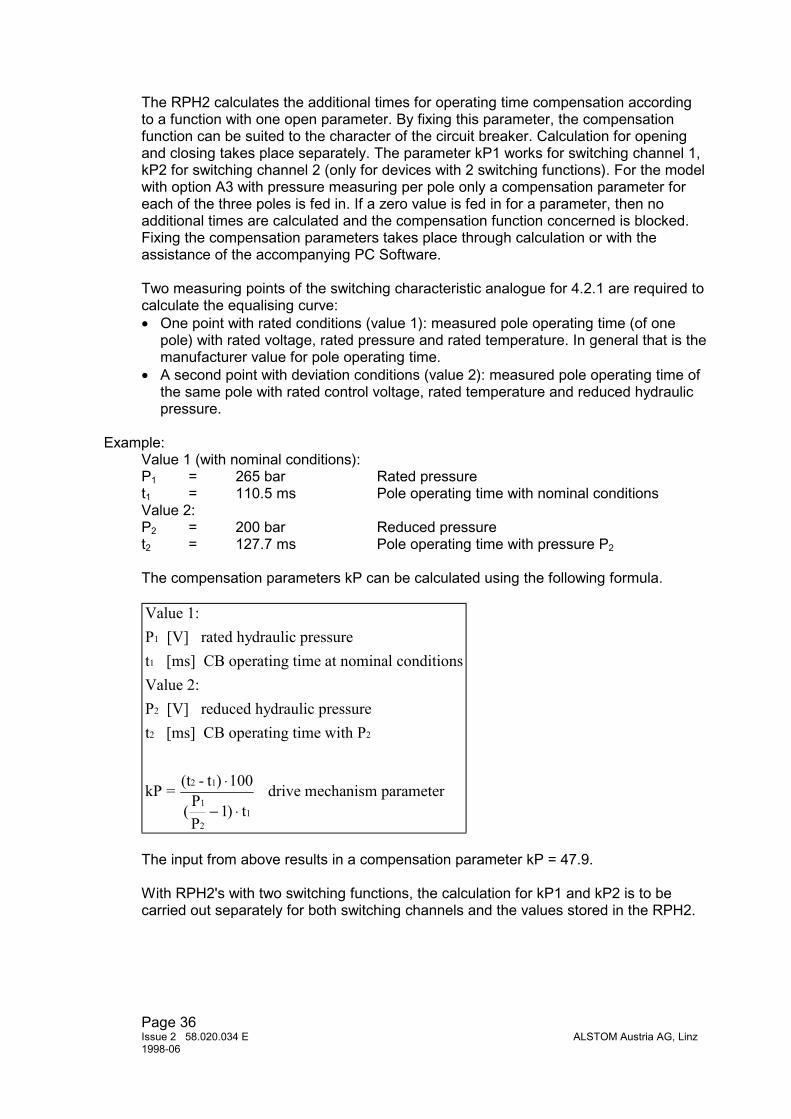
The RPH2 calculates the additional times for operating time compensation accordingto a function with one open parameter. By fixing this parameter, the compensationfunction can be suited to the character of the circuit breaker. Calculation for openingand closing takes place separately. The parameter kP1 works for switching channel 1,kP2 for switching channel 2 (only for devices with 2 switching functions). For the modelwith option A3 with pressure measuring per pole only a compensation parameter foreach of the three poles is fed in. If a zero value is fed in for a parameter, then noadditional times are calculated and the compensation function concerned is blocked.Fixing the compensation parameters takes place through calculation or with theassistance of the accompanying PC Software.
Two measuring points of the switching characteristic analogue for 4.2.1 are required tocalculate the equalising curve:• One point with rated conditions (value 1): measured pole operating time (of one
pole) with rated voltage, rated pressure and rated temperature. In general that is themanufacturer value for pole operating time.
• A second point with deviation conditions (value 2): measured pole operating time ofthe same pole with rated control voltage, rated temperature and reduced hydraulicpressure.
Example:Value 1 (with nominal conditions):P1 = 265 bar Rated pressuret1 = 110.5 ms Pole operating time with nominal conditionsValue 2:P2 = 200 bar Reduced pressuret2 = 127.7 ms Pole operating time with pressure P2
The compensation parameters kP can be calculated using the following formula.
Value 1:P [V] rated hydraulic pressuret [ms] CB operating time at nominal conditionsValue 2:P [V] reduced hydraulic pressuret [ms] CB operating time with P
kP = (t - t ) 100PP
t drive mechanism parameter
1
1
2
2 2
2 1
1
21
⋅
− ⋅( )1
The input from above results in a compensation parameter kP = 47.9.
With RPH2's with two switching functions, the calculation for kP1 and kP2 is to becarried out separately for both switching channels and the values stored in the RPH2.

Page 37ALSTOM Austria AG, Linz Issue 2 58.020.034 E
1998-06
4.2.4 Specifications for the external sensorsFor measuring pressure and temperature, external sensors with integrated transducerare necessary which are not part of the delivery.
The integrated transducers must meet the following requirements:
Auxiliary voltage 24 VDC (supplied by the RPH2)2 conductor systemOutput signal 4 mA to 20 mA
Such transducers can be obtained from many manufacturers. The measuring range ofthe sensors adjust itself to the respective requirements.However, unnecessarily large measuring ranges reduce the measuring accuracy of theRPH2. The RPH2 measuring input is adapted to the measuring range of the sensorthrough parameterisation.
Transducer installation is carried out according to the manufacturer's guidelines.Likewise, the connection cables to the RPH2 must be selected according to themanufacturer's information. If no information is available, we recommend a shieldedtwo-wire cable per transducer, or at least a twisted pair of wires.
4.2.5 Adaptive ControlRPH2 with analogue module A and signal module S provide the additional feature of anadaptive control to compensate the long time drift in operating time of the CB drive. Theactual operating times of the poles are measured by the signal module. A weightingfactor in the range of 0 to 0.5, step 0.05 (0 = function is disabled) is used for controllingthis function. A fraction (depending on the weighting factor) of the time differencebetween the operating time of the last operation and the operation before is added tothe actual operating time. Additional operating times due to compensation functions arenot taken into consideration, so the pure long time drift of the drive mechanism iscompensated. The additional adaptive times are displayed and a function is available toreset these times.
The compensation of the time shift between the main contacts and the auxiliary contactsof the breaker poles must be done very exactly to avoid errors in measuring of theactual operating times.
• Time deviations of the measured values greater than 10 ms are not considered. (nooperation of the CB or incorrect measurement of operating times).
• Additional adaptive time is limited to 1 ms from one operation to the next.• If the operating time corrected by adaptive control has drifted away from the pre-set
operating times for more than±5 ms for opening±10 ms for closing
the alarm "Drive mech. Failure" is generated.
The value of the weighting factor depends on the type of drive mechanism. We proposea value of 0.25 to 0.30 for all types of mechanism.

Page 38Issue 2 58.020.034 E ALSTOM Austria AG, Linz1998-06
4.3 Current Module Option I
A current measuring module is available to make the switching of large transformersand reactors easy when putting the RPH2 Point-on-Wave Controller into operation.With this the inrush current can be recorded and graphically displayed during theswitching process. Data for the last 4 switching operations are stored in a non-volatilememory and can be analysed on the display. Primary values are shown after feeding inthe current transformer current ratio.
For every phase there is an input for each 1 A and 5 A available. Because the currentinputs have a short time withstand of 100 xln, current measurement can be carried outover a measuring core as well as a protection core of the current transformer.

Page 39ALSTOM Austria AG, Linz Issue 2 58.020.034 E
1998-06
5 RPH2 MENUE SYSTEM
5.1 System data
- - R P H 2 - 2 S I A 3 - -> S y s t e m D a t a
C B D a t aA n a l o g D a t aA l a r m s
1 2 3 4 5 6 7 8L 1 L 2 L 3
Enter + - Esc
5.1.1 PasswordThe factory-setting of the-password is "0000". To activate the password you mustchange to the submenu [System Data/Password]. The actual status (‘active’ or ‘off’) isshown in the bottom-left corner of the display. Type in the correct password and confirmthe assumption by pressing the ‘Enter’-button (see chapter 2.5). The display shows‘active’ and the green LED ‘ready’ starts blinking if the password is correct (see chapter2.4.3.1).The password will be deactivated automatically if no button is pressed for more than 90seconds.
S y s t e m D a t a> P a s s w o r d
S y s t e m F r e q u e n c yC o n t r o l V o l t a g eR a t e d P r e s s u r e
0 0 0 01 2 3 4 5 6 7 8
L 1 L 2 L 3
5.1.2 System FrequencyAfter activating this function by pressing the ‘Enter’-button you can choose any item ofthe list by pressing the ‘+’- or the ‘-’-button (see chapter 2.5).
Available items: 50 Hz, 60 Hz, 16 2/3 Hz

Page 40Issue 2 58.020.034 E ALSTOM Austria AG, Linz1998-06
S y s t e m D a t aP a s s w o r d
> S y s t e m F r e q u e n c yC o n t r o l V o l t a g eR a t e d P r e s s u r e
5 0 H z1 2 3 4 5 6 7 8
L 1 L 2 L 3
5.1.3 Control VoltageType in the rated voltage of your CB-coil (available only for modules RPH2-xxA0, RPH2-xxA1, RPH2-xxA3).This value acts as base for the calculation of the additional compensation value of themechanical operating time of the CB.
S y s t e m D a t aP a s s w o r dS y s t e m F r e q u e n c y
> C o n t r o l V o l t a g eR a t e d P r e s s u r e
2 3 0 , 0 V1 2 3 4 5 6 7 8
L 1 L 2 L 3
5.1.4 Rated PressureType in the value of the rated pressure of the hydraulic system of your CB-drive(available only for module RPH2-xxA1, RPH2-xxA3). This value acts as base for thecalculation of the compensation value of the operating time of the CB.
S y s t e m D a t aS y s t e m F r e q u e n c yC o n t r o l V o l t a g e
> R a t e d P r e s s u r eS w i t c h i n g P r o g r a m
1 0 b a r1 2 3 4 5 6 7 8
L 1 L 2 L 3
5.1.5 Switching ProgramSelect the suitable switching program by pressing the ‘+’- or ‘-’-button:
• transformer• shunt reactor• capacitor bank• user program

Page 41ALSTOM Austria AG, Linz Issue 2 58.020.034 E
1998-06
S y s t e m D a t aC o n t r o l V o l t a g eR a t e d P r e s s u r e
> S w i t c h i n g P r o g r a mL a n g u a g e
T r a n s f o r m e r1 2 3 4 5 6 7 8
L 1 L 2 L 3
5.1.5.1 User Program
You can define your own switching moments for each phase by selecting the ‘UserProgram’.
Note: If you select ‘user program’ you have to select the rated frequency first (seechapter 5.2).
Adjustable switching moments:
T_C1 Neutral isolated:Type in the switching moments of the three phases L1/L2/L3 for channel 1 with isolatedneutral.
U s e r P r o g r a m> T _ C 1 N e u t r . i s o l a t e d
T _ C 1 N e u t r . g r o u n d e dT _ C 2 N e u t r . i s o l a t e dT _ C 2 N e u t r . g r o u n d e d
0 , 0 0 , 0 0 , 0 m s1 2 3 4 5 6 7 8
L 1 L 2 L 3
T_C1 Neutral grounded:Type in the switching moments of the three phases L1/L2/L3 for channel 1 withgrounded neutral.
The following two submenus are available only for module RPH2-2xx (module with twoswitching channels):
T_C2 Neutral isolated:Type in the switching moments of the three phases L1/L2/L3 for channel 2 with isolatedneutral.
T_C2 Neutral grounded:Type in the switching moments of the three phases L1/L2/L3 for channel 2 withgrounded neutral.

Page 42Issue 2 58.020.034 E ALSTOM Austria AG, Linz1998-06
5.1.6 Function Channel 1For the module RPH2-1xxx you have to select whether if you use the RPH2 for closingor opening of the CB.
5.1.7 LanguageSelect your preferred language.Available languages:
• German• English• French• User language
S y s t e m D a t aR a t e d P r e s s u r eS w i t c h i n g P r o g r a m
> L a n g u a g eT i m e / D a t e
E n g l i s h1 2 3 4 5 6 7 8
L 1 L 2 L 3
Note: You can load the menutext in any language with the RPH-Tool (PC-basedsoftware). If there any problems with the loaded language file you can return to theEnglish menus: Turn the key-operated switch to "OFF", press the "Quitt" button andmeanwhile return the key-operated switch back to "OPERATION".
5.1.8 Time / DateType in the actual date and time. The format for date and time is:
”YYYY-MM-DD HH:MM”.
S y s t e m D a t aS w i t c h i n g P r o g r a mL a n g u a g e
> T i m e / D a t eN e w P a s s w o r d
1 9 9 6 - 1 2 - 0 6 1 7 : 5 11 2 3 4 5 6 7 8
L 1 L 2 L 3
Note: Type in only correct values for date and time.
Note: There are no problems with a date after 2000-01-01.
5.1.9 New PasswordIf you want to change the actual password simply type in the new password.Possible values are all numbers between ‘0000’ and ‘9999’.

Page 43ALSTOM Austria AG, Linz Issue 2 58.020.034 E
1998-06
S y s t e m D a t aL a n g u a g eT i m e / D a t e
> N e w P a s s w o r dS e l f t e s t S t a r t
0 0 0 01 2 3 4 5 6 7 8
L 1 L 2 L 3
Note: If you have forgotten the selected password, you can ask for a temporarypassword (call your local ALSTOM representative)
5.1.10 Selftest StartYou can activate the selftest-facility by pressing the ‘Enter’-button.
The selftest-facility checks the internal function of the module and the switching outputs.
S y s t e m D a t aT i m e / D a t eN e w P a s s w o r d
> S e l f t e s t S t a r tS e l f t e s t I n t e r v a l
Y E S1 2 3 4 5 6 7 8
L 1 L 2 L 3
Note: You can activate the selftest with the key-operated-switch too (see chapter 2.4.2).
5.1.11 Selftest IntervalType in the desired interval between the automatic selftests.
The possible range is from 0,0 hours (shortest interval is 0,1 hour = 6 minutes) to 500hours. Choosing a value of 0,0 hours deactivates the automatic selftest-facility.
S y s t e m D a t aT i m e / D a t eN e w P a s s w o r dS e l f t e s t S t a r t
> S e l f t e s t I n t e r v a l2 4 , 0 H r
1 2 3 4 5 6 7 8L 1 L 2 L 3
In the menu [Aux. Functions][Error Type] the type errors are displayed (see 5.6.3).
Page 44Issue 2 58.020.034 E ALSTOM Austria AG, Linz1998-06
5.2 CB Data
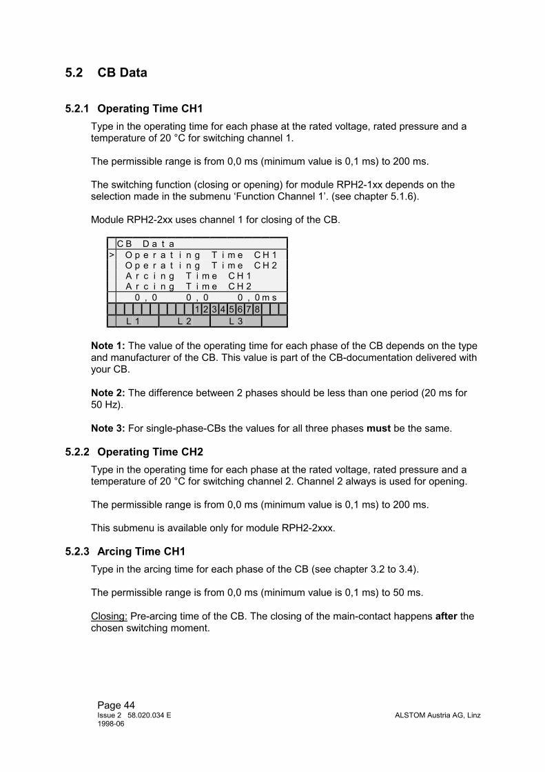
5.2.1 Operating Time CH1Type in the operating time for each phase at the rated voltage, rated pressure and atemperature of 20 °C for switching channel 1.
The permissible range is from 0,0 ms (minimum value is 0,1 ms) to 200 ms.
The switching function (closing or opening) for module RPH2-1xx depends on theselection made in the submenu ‘Function Channel 1’. (see chapter 5.1.6).
Module RPH2-2xx uses channel 1 for closing of the CB.
C B D a t a> O p e r a t i n g T i m e C H 1
O p e r a t i n g T i m e C H 2A r c i n g T i m e C H 1A r c i n g T i m e C H 2
0 , 0 0 , 0 0 , 0 m s1 2 3 4 5 6 7 8
L 1 L 2 L 3
Note 1: The value of the operating time for each phase of the CB depends on the typeand manufacturer of the CB. This value is part of the CB-documentation delivered withyour CB.
Note 2: The difference between 2 phases should be less than one period (20 ms for50 Hz).
Note 3: For single-phase-CBs the values for all three phases must be the same.
5.2.2 Operating Time CH2Type in the operating time for each phase at the rated voltage, rated pressure and atemperature of 20 °C for switching channel 2. Channel 2 always is used for opening.
The permissible range is from 0,0 ms (minimum value is 0,1 ms) to 200 ms.
This submenu is available only for module RPH2-2xxx.
5.2.3 Arcing Time CH1Type in the arcing time for each phase of the CB (see chapter 3.2 to 3.4).
The permissible range is from 0,0 ms (minimum value is 0,1 ms) to 50 ms.
Closing: Pre-arcing time of the CB. The closing of the main-contact happens after thechosen switching moment.

Page 45ALSTOM Austria AG, Linz Issue 2 58.020.034 E
1998-06
Opening: Arcing time of the CB. The opening of the main-contact happens before thezero-crossing of the current.
C B D a t aO p e r a t i n g T i m e C H 1O p e r a t i n g T i m e C H 2
> A r c i n g T i m e C H 1A r c i n g T i m e C H 2
0 , 0 0 , 0 0 , 0 m s1 2 3 4 5 6 7 8
L 1 L 2 L 3
5.2.4 Arcing Time CH2This submenu is available only for module RPH2-2xxx. It works as for channel 1 exceptthat channel 2 always is used for opening.
5.2.5 Auxiliary Timeshift CH1This value is used for compensating the time lag between the main-contact and theauxiliary-contact of the CB (see chapter 4.1.2.1).
The permissible range is from -25,5 ms to +25,5 ms.
C B D a t aA r c i n g T i m e C H 1A r c i n g T i m e C H 2
> A u x . T i m e s h i f t C H 1A u x . T i m e s h i f t C H 2+ 0 , 0 + 0 , 0 + 0 , 0 m s
1 2 3 4 5 6 7 8L 1 L 2 L 3
This submenu is available only with module RPH2-xxS.
5.2.6 Auxiliary Timeshift CH2This submenu is available only for module RPH2-2xxx. It works as for channel 1 exceptthat channel 2 always is used for opening.
5.2.7 Adaptive ControlThis menu opens a submenu for controlling the this function (see also 4.2.5)
C B D a t aA u x . T i m e s h i f t C H 2
> A d a p t i v C o n t r o l - >C o m p e n s a t i o nk U 1 V o l t a g e C H 1
1 2 3 4 5 6 7 8L 1 L 2 L 3

Page 46Issue 2 58.020.034 E ALSTOM Austria AG, Linz1998-06
This submenu and the following menus are available only with module RPH2-xSAx.
5.2.7.1 Weighting FactorThis factor defines the friction of time difference added to the operating time.
A d a p t i v C o n t r o l> W e i g h t i n g F a c t o r
A d a p t i v e T i m e s C H 1A d a p t i v e T i m e s C H 2R e s e t A d a p t i v e T i m e
0 . 2 51 2 3 4 5 6 7 8
L 1 L 2 L 3
The permissible range is from 0.00 to 0.50 (step 0.05).A value of 0.00 disables this function.
5.2.7.2 Adaptive Times CH1Here the adaptive times for each pole related to switching channel 1 are displayed.
5.2.7.3 Adaptive Times CH2Here the adaptive times for each pole related to switching channel 2 are displayed.
5.2.7.4 Reset Adaptive TimesThis function allows to reset the additional times due to adaptive control to zero. Afterthis, the RPH2 operates with the pre-set pole operating times.
5.2.8 CompensationIf you select ‘NO’ all compensation functions are blocked.If you select ‘YES’ compensation is active (for description see chapter 4.2)
C B D a t aA u x . T i m e s h i f t C H 1A u x . T i m e s h i f t C H 2
> C o m p e n s a t i o nk U 1 V o l t a g e C H 1
Y E S1 2 3 4 5 6 7 8
L 1 L 2 L 3
5.2.9 kU1 Voltage CH1Type in the calculated value for compensation of changes of the control voltage (seechapter 4.2.1).
The permissible range is from 0,0 to 150,0.

Page 47ALSTOM Austria AG, Linz Issue 2 58.020.034 E
1998-06
C B D a t aA u x . T i m e s h i f t C H 2C o m p e n s a t i o n
> k U 1 V o l t a g e C H 1k P 1 P r e s s u r e C H 1
3 0 , 31 2 3 4 5 6 7 8
L 1 L 2 L 3
This submenu is available only with modules RPH2-xxA0, RPH2-xxxA1, RPH2-xxxA3.
5.2.10 kP1 Pressure CH1same as 5.2.9, but for pressure compensation for channel 1.
This submenu is available only with modules RPH2-xxxA1, RPH2-xxxA3.
5.2.11 Temperature Compensation CH1This submenu enables or disables the temperature compensation.
C B D a t ak U 1 V o l t a g e C H 1k P 1 P r e s u r e C H 1
> T e m p . C o m p . C H 1T a b l e T e m p . C H 1 - >
O N1 2 3 4 5 6 7 8
L 1 L 2 L 3
This submenu is available only with modules RPH2-xxA0, RPH2-xxxA1, RPH2-xxxA3.
5.2.12 Table Temp. CH1This menu opens a submenu for setting the values for temperature compensation.
5.2.12.1 Delta_t xx°CHere the 11 values of Delta_t(T) for defining the temperature compensation function canbe entered to the RPH2 (see also 4.2.2).
T a b l e T e m p . C H 1 - >D e l t a _ t - 5 0 ° C
> D e l t a _ t - 4 0 ° CD e l t a _ t - 3 0 ° CD e l t a _ t - 2 0 ° C
+ 5 . 3 m s1 2 3 4 5 6 7 8
L 1 L 2 L 3
The permissible range for Delta_t is from -10.0 ms to +25.0 ms.

Page 48Issue 2 58.020.034 E ALSTOM Austria AG, Linz1998-06
5.2.13 kU2 Voltage CH2same as 5.2.9, but for control voltage compensation for channel 2.
This submenu is available only with modules RPH2-xxA0, RPH2-xxxA1, RPH2-xxxA3.
5.2.14 kP2 Pressure CH2same as 5.2.10, but for temperature compensation for channel 2.
This submenu is available only with modules RPH2-xxxA1, RPH2-xxxA3.
5.2.15 Temperature Compensation CH2same as 5.2.11, but for temperature compensation for channel 2.
This submenu is available only with modules RPH2-xxA0, RPH2-xxxA1, RPH2-xxxA3.
5.2.16 Table Temp. CH1same as 5.2.12, but for temperature compensation for channel 2.
5.2.16.1 Delta_t xx°Csame as 5.2.12.1, but for temperature compensation for channel 2.
5.3 Analogue Data
5.3.1 ThresholdsThe following submenus are depending on the configuration of the RPH 2 obtained.Exceeding of limit-settings cause an alarm, if set (see chapter 5.4).
A n a l o g D a t a> T r e s h o l d s - >
C T R a t e d C u r r . p r i mC T R a t e d C u r r . s e cA c t u a l C o n t r . V o l t a g e
1 2 3 4 5 6 7 8L 1 L 2 L 3
5.3.1.1 Current max.
Type in the allowed maximum value (peak-value) of the current during the switchingoperation. If the current during a switching operation exceeds this limit an alarm isgenerated.
The permissible range is from 0 A to 9999 A.

Page 49ALSTOM Austria AG, Linz Issue 2 58.020.034 E
1998-06
T r e s h o l d s - >> C u r r e n t m a x ( p e a k )
O p . V o l t a g e m a xO p . V o l t a g e m i nT e m p e r a t u r e m a x
5 0 0 A1 2 3 4 5 6 7 8
L 1 L 2 L 3
This submenu is only available for module RPH2-xxI.
5.3.1.2 Control Voltage max.Type in the upper limit for the control voltage. If the measured value of the controlvoltage becomes higher than the limit an alarm is generated.
The permissible range is from 35 V to 300 V.
T r e s h o l d s - >C u r r e n t m a x ( p e a k )
> C o n t r o l V o l t a g e m a xC o n t r o l V o l t a g e m i nT e m p e r a t u r e m a x
2 4 2 , 0 V1 2 3 4 5 6 7 8
L 1 L 2 L 3This submenu is available only with modules RPH2-xxA0, RPH2-xxA1, RPH2-xxA3.
5.3.1.3 Control Voltage min.Type in the lower limit for the control voltage. If the measured value of the controlvoltage becomes lower than the limit an alarm is generated.
The permissible range is from 35 V to 300 V.
T r e s h o l d s - >C u r r e n t m a x ( p e a k )O p . V o l t a g e m a x
> O p . V o l t a g e m i nT e m p e r a t u r e m a x
2 0 0 , 0 V1 2 3 4 5 6 7 8
L 1 L 2 L 3
This submenu is available only with modules RPH2-xxA0, RPH2-xxA1, RPH2-xxA3.
5.3.1.4 Temperature max.Type in the upper limit for the ambient temperature of the CB. If the measured value ofthe temperature becomes higher than the limit an alarm is generated.
The permissible range is from -100° C to +100° C.

Page 50Issue 2 58.020.034 E ALSTOM Austria AG, Linz1998-06
T r e s h o l d s - >O p . V o l t a g e m a xO p . V o l t a g e m i n
> T e m p e r a t u r e m a xT e m p e r a t u r e m i n
+ 5 0 , 0 C1 2 3 4 5 6 7 8
L 1 L 2 L 3
This submenu is available only with modules RPH2-xxA0, RPH2-xxA1, RPH2-xxA3.
5.3.1.5 Temperature min.Type in the lower limit of the ambient temperature of the CB. If the measured value ofthe temperature becomes lower than the limit an alarm is generated.
The permissible range is from -100° C to +100° C.
T r e s h o l d s - >O p . V o l t a g e m i nT e m p e r a t u r e m a x
> T e m p e r a t u r e m i nP r e s s u r e m a x
- 5 0 . 0 C1 2 3 4 5 6 7 8
L 1 L 2 L 3This submenu is available only for module RPH2-xxA0, RPH2-xxA1, RPH2-xxA3.
5.3.1.6 Pressure max.Type in the upper limit of the hydraulic pressure of the CB. If the measured value of thetemperature becomes higher than the limit an alarm is generated.
The permissible range is from 0 bar to 1000 bar.
T r e s h o l d s - >T e m p e r a t u r e m a xT e m p e r a t u r e m i n
> P r e s s u r e m a xP r e s s u r e m i n
3 5 0 b a r1 2 3 4 5 6 7 8
L 1 L 2 L 3
This submenu is available only with modules RPH2-xxA1, RPH2-xxA3.
5.3.1.7 Pressure min.Type in the lower limit of the hydraulic pressure of the CB. If the measured value of thetemperature becomes lower than the limit an alarm is generated.
The permissible range is from 0 bar to 1000 bar.

Page 51ALSTOM Austria AG, Linz Issue 2 58.020.034 E
1998-06
T r e s h o l d s - >T e m p e r a t u r e m a xT e m p e r a t u r e m i nP r e s s u r e m a x
> P r e s s u r e m i n1 8 0 b a r
1 2 3 4 5 6 7 8L 1 L 2 L 3
This submenu is available only with modules RPH2-xxA1, RPH2-xxA3.
5.3.2 CT Rated Current primType in the rated primary current of your current transducer.
The permissible range is from 0 A to 5000 A.
A n a l o g D a t aT r e s h o l d s - >
> C T R a t e d C u r r . p r i mC T R a t e d C u r r . s e cA c t u a l C o n t r . V o l t a g e
5 0 0 A1 2 3 4 5 6 7 8
L 1 L 2 L 3
This submenu is available only with module RPH2-xxI.
5.3.3 CT Rated Current secType in the rated secondary current of your current transducer.
Permissible values are 1 A and 5 A.
A n a l o g D a t aT r e s h o l d s - >C T R a t e d C u r r . p r i m
> C T R a t e d C u r r . s e cA c t u a l C o n t r . V o l t a g e
5 A1 2 3 4 5 6 7 8
L 1 L 2 L 3
This submenu is available only for module RPH2-xxI.
Note: The current transformer has to be connected to the correct terminal of the RPH2(1 A or 5 A, see wiring diagram).

Page 52Issue 2 58.020.034 E ALSTOM Austria AG, Linz1998-06
5.3.4 Actual Control VoltageType in the measured value of the actual control voltage. This input calibrates theinternal voltage measurement. This value acts as base for the calculation ofcompensation of the switching moment.
The permissible range is from 35 V to 300 V.
A n a l o g D a t aC T R a t e d C u r r . p r i mC T R a t e d C u r r . s e c
> A c t u a l C o n t r . V o l t a g eT e m p e r a t u r e - >
1 1 2 , 2 V1 2 3 4 5 6 7 8
L 1 L 2 L 3
This submenu is available only with modules RPH2-xxA0, RPH2-xxA1, RPH2-xxA3.
Determine the correct value:Measure the actual value of the control voltage on terminal -X6:10 and -X6:11 with ancalibrated voltmeter and type in this value.Type in the determined value.
Note:This input calibrates the voltage measurement function. The correct input of thisvalue is absolutely necessary. You cannot calibrate the RPH2 with the PC-software‘RPH-Tool’.In the Normal-Mode (Ready-LED is steady-light) the measured voltage is displayed.After calibrating the voltage measurement check the correct function by monitoring thedisplay.
5.3.5 TemperatureThe following submenus are available only with modules RPH2-xxA0, RPH2-xxA1,RPH2-xxA3.In this submenu the temperature transducer is calibrated.
A n a l o g D a t aC T R a t e d C u r r . s e cA c t u a l C o n t r . V o l t a g e
> T e m p e r a t u r e - >P r e s s u r e - >
1 2 3 4 5 6 7 8L 1 L 2 L 3
5.3.5.1 Value at 4 mAType in the rated value of the temperature transducer at an output current of 4 mA. Thisinformation is part of the documentation of the temperature transducer.

Page 53ALSTOM Austria AG, Linz Issue 2 58.020.034 E
1998-06
T e m p e r a t u r e - >> V a l u e a t 4 m A
V a l u e a t 2 0 m A
- 4 0 , 0 C1 2 3 4 5 6 7 8
L 1 L 2 L 3
5.3.5.2 Value at 20 mAType in the rated value of the temperature transducer at an output current of 20 mA.This information is part of the documentation of the temperature transducer.
T e m p e r a t u r e - >V a l u e a t 4 m A
> V a l u e a t 2 0 m A
+ 1 0 0 , 0 C1 2 3 4 5 6 7 8
L 1 L 2 L 3
5.3.6 PressureThese submenus are available only with modules RPH2-xxA1, RPH2-xxA3.In the following submenus the pressure transducer can be calibrated.
A n a l o g D a t aC T R a t e d C u r r . s e cA c t u a l C o n t r . V o l t a g eT e m p e r a t u r e - >
> P r e s s u r e - >
1 2 3 4 5 6 7 8L 1 L 2 L 3
5.3.6.1 Value at 4 mAType in the rated value of the pressure transducer at an output current of 4 mA. Thisinformation is part of the documentation of the pressure transducer.
P r e s s u r e - >> V a l u e a t 4 m A
V a l u e a t 2 0 m A
0 b a r1 2 3 4 5 6 7 8
L 1 L 2 L 3
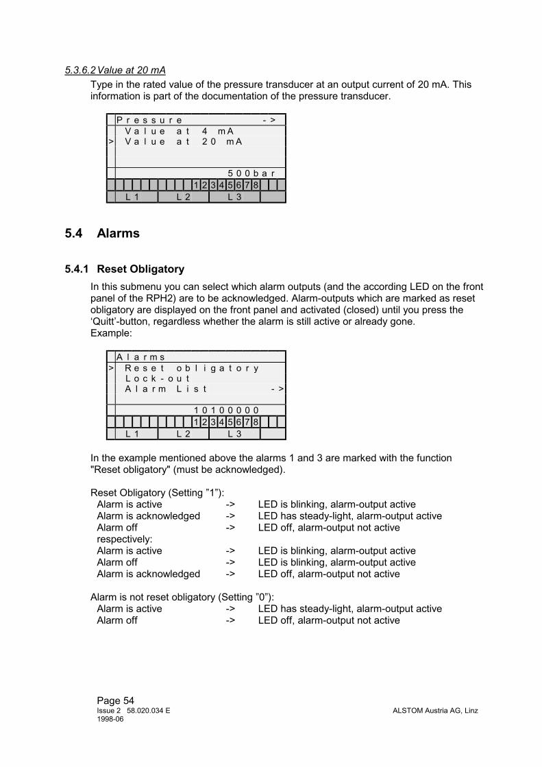
Page 54Issue 2 58.020.034 E ALSTOM Austria AG, Linz1998-06
5.3.6.2 Value at 20 mAType in the rated value of the pressure transducer at an output current of 20 mA. Thisinformation is part of the documentation of the pressure transducer.
P r e s s u r e - >V a l u e a t 4 m A
> V a l u e a t 2 0 m A
5 0 0 b a r1 2 3 4 5 6 7 8
L 1 L 2 L 3
5.4 Alarms
5.4.1 Reset ObligatoryIn this submenu you can select which alarm outputs (and the according LED on the frontpanel of the RPH2) are to be acknowledged. Alarm-outputs which are marked as resetobligatory are displayed on the front panel and activated (closed) until you press the‘Quitt’-button, regardless whether the alarm is still active or already gone.Example:
A l a r m s> R e s e t o b l i g a t o r y
L o c k - o u tA l a r m L i s t - >
1 0 1 0 0 0 0 01 2 3 4 5 6 7 8
L 1 L 2 L 3
In the example mentioned above the alarms 1 and 3 are marked with the function"Reset obligatory" (must be acknowledged).
Reset Obligatory (Setting ”1”):Alarm is active -> LED is blinking, alarm-output activeAlarm is acknowledged -> LED has steady-light, alarm-output activeAlarm off -> LED off, alarm-output not activerespectively:Alarm is active -> LED is blinking, alarm-output activeAlarm off -> LED is blinking, alarm-output activeAlarm is acknowledged -> LED off, alarm-output not active
Alarm is not reset obligatory (Setting ”0”):Alarm is active -> LED has steady-light, alarm-output activeAlarm off -> LED off, alarm-output not active

Page 55ALSTOM Austria AG, Linz Issue 2 58.020.034 E
1998-06
Note: With the function "reset obligatory" you can change an alarm-message from thetype pulse type to a steady alarm type (see 5.4.3).
5.4.2 Lock-OutHere you can mark each of the 7 alarm outputs to produce a blocking of the device in caseof the corresponding alarm occurs.That means:No switching operation is possible, the green LED is dark and the contact "Device not ready"(-X6:12/13) is closed.
Some actions or alarms cause a lock out in any case ,also without activating the respondingalarm (LED dark, contact -X6:12-13 is closed):• Keyswitch is "OFF"• Relay starting up• Reference voltage is missing• Frequency not in permitted range• Neutral earthing switch in intermediate position
Example:
A l a r m sR e s e t o b l i g a t o r y
> L o c k - o u tA l a r m L i s t - >
0 0 1 0 0 0 0 01 2 3 4 5 6 7 8
L 1 L 2 L 3
In the example mentioned above the activating of alarm 3 blocks the RPH2. Nooperation is possible, until the "Quit" button is pressed. The output contact "Device notready" (-X6:12/13) is closed.
5.4.3 Alarm ListThe following submenus are depending on the configuration of the RPH2. Each internalalarm (message) can be assigned to up to 7 alarm-outputs. The assignment is madethrough the setting of a ‘1’ at the corresponding display-unit.
Example:
A l a r m L i s t - >F r e q u e n c y m i nF r e q u e n c y m a x
> C u r r e n t m a x ( p e a k )* R e f . V o l t a g e F a i l u r e
0 0 1 0 0 1 0 01 2 3 4 5 6 7 8
L 1 L 2 L 3

Page 56Issue 2 58.020.034 E ALSTOM Austria AG, Linz1998-06
In the example mentioned above the alarm-message ‘Current max. (peak)’ is assignedto alarm-output 3 and alarm-output 6.
The asterisk (‘*’) at the position ‘Ref. Voltage Failure’ in the picture above indicates thatthe fault ‘Ref. Voltage Failure’ is pending, that means the reference voltage is missing.
Pulse-alarm:If an alarm-message is a pulse, this alarm-message is active only for a period of 0,5seconds. If this alarm-message is assigned to an alarm-output which is marked as ‘resetobligatory’, the alarm-output remains active until this alarm is acknowledged.
Note: The assignment of an alarm-message to the alarm-output number 8 has noeffect.
5.4.3.1 Lock-outThis is only a summary alarm. It is generated by other alarms which cause a blocking of therelay. It is active when the device is blocked (see 5.4.2). The alarm itself causes no blockingof the device!
5.4.3.2 Frequency minThe reference voltage (phase L1) is monitored permanently. If the lower limit of thefrequency is reached, an alarm-message ‘Frequency min.’ is generated.
Limits:Rated Frequency Lower Limit50 Hz 45 Hz60 Hz 54 Hz16 2/3 Hz 15 Hz
Note: The monitoring of the frequency is active only if the reference voltage isconnected to the device. If the reference voltage is missing, no alarm ‘Frequency min.’ isgenerated.
5.4.3.3 Frequency max.The reference voltage is monitored permanently on phase L1. If the upper limit of thefrequency is reached, an alarm-message ‘Frequency max.’ is generated.
Limits:Rated Frequency Upper Limit50 Hz 55 Hz60 Hz 66 Hz16 2/3 Hz 18,26 Hz
Note: The monitoring of the frequency is active only, if the reference voltage isconnected to the device. If the reference voltage is missing, no alarm ‘Frequency min.’ isgenerated.

Page 57ALSTOM Austria AG, Linz Issue 2 58.020.034 E
1998-06
5.4.3.4 Current max. (peak)This alarm-message is generated if the setting of the current maximum (peak value) isreached or exceeded during a switching operation in one or more phases (thresholdssee 5.3.1.1)
The peak-value of the current is monitored, not the RMS-value.
This alarm-message is a pulse (see chapter 5.4.3. Pulse-alarm).
This alarm-message is available only for module RPH2-xxI.
5.4.3.5 Reference Voltage FailureThis alarm-message is generated if the reference voltage is missing for more than2 seconds.
Note: This alarm-message blocks the RPH2 in any case, regardless whether the alarmis set for blocking or not (see chapter 5.4.2).
5.4.3.6 RTC Impulse FailureThis alarm-message is generated if the minute-pulse is missing.
5.4.3.7 Neutral intermediateThis alarm-message is generated if the position of the ‘Neutral-switch’ is not defined.
Note: This alarm-message blocks the RPH2 in any case, regardless whether the alarmis set for blocking or not (see chapter 5.4.2).
5.4.3.8 Neutral groundedThis message indicates, that the ‘Neutral-switch’ is in position ‘grounded’. If the position‘grounded’ is indicated, the RPH2 uses the parameter-set ‘Neutral grounded’.
Note: This message is not an alarm-message but may be helpful for supervising
5.4.3.9 Neutral isolatedThis message indicates, that the ‘Neutral-switch’ is in position ‘isolated’. If the position‘isolated’ is indicated, the RPH2 uses the parameter-set ‘Neutral isolated’ (see 5.4.3.8).
5.4.3.10 Selftest ERRORThis alarm-message is generated when the automatic selftest discovers an internal error(output circuit is not working correct).
This alarm-message is a pulse (see chapter 5.4.3. Pulse-alarm).
Note: This alarm-message blocks the RPH2 in any case, regardless whether the alarmis set for blocking or not (see chapter 5.4.2).
5.4.3.11 Selftest CH1 ERRORThis alarm-message is the detailed message from 5.4.3.10 related to channel 1.

Page 58Issue 2 58.020.034 E ALSTOM Austria AG, Linz1998-06
This alarm-message is a pulse (see chapter 5.4.3. Pulse-alarm).
5.4.3.12 Selftest CH2 ERRORThis alarm-message is the detailed message from 5.4.3.10 related to channel 2.
This alarm-message is a pulse (see chapter 5.4.3. Pulse-alarm).
This alarm-message is available only for module RPH2-2xx.
5.4.3.13 Command Time CH1 minThis alarm-message is generated when the command time for channel 1 (the function isdepending on configuration of the RPH2 and the ‘Function Channel 1’ - chapter 4.6) isto short, i. e. perhaps not all three phase are switched within this time.
The alarm is generated if the duration of the command impulse is less than 100 ms.
This alarm-message is a pulse (see chapter 5.4.3. Pulse-alarm).
5.4.3.14 Command Time CH2 minThis alarm-message is generated when the command time for channel 2 (opening) is toshort.
The alarm is generated if the duration of the command impulse is less than 100 ms.
This alarm-message is a pulse (see chapter 5.4.3. Pulse-alarm).
This alarm-message is available only for module RPH2-2xx .
5.4.3.15 Operating Time minThis alarm-message is generated when the measured operating time differs more than2 ms of the calculated operation time (measured time is shorter).
This alarm-message is a pulse (see chapter 5.4.3. Pulse-alarm).
This alarm-message is available only for module RPH2-xxS.
5.4.3.16 Operating Time max.This alarm-message is generated when the measured operating time differs more than2 ms of the calculated operation time (measured time is longer).
This alarm-message is a pulse (see chapter 5.4.3. Pulse-alarm).
This alarm-message is available only for module RPH2-xxS.

Page 59ALSTOM Austria AG, Linz Issue 2 58.020.034 E
1998-06
5.4.3.17 Drive mech. FailureThis alarm-message is generated when:• The monitoring of the CB-position is undefined.• The operating time corrected by adaptive control has drifted away for more than 5 ms
for opening and 10 ms for closing from the pre-set operating times (only with adaptivecontrol, see 4.2.5).
This alarm-message is a pulse (see chapter 5.4.3. Pulse-alarm).
This alarm-message is available only for module RPH2-xxS.
5.4.3.18 Archive Full
This alarm-message indicates that the archive is nearly full.
This alarm-message is a pulse (see chapter 5.4.3. Pulse-alarm).
Note: The archive is capable to store 1000 switching operations. When the 900thswitching operation is stored in the archive the alarm-message is generated. Eachswitching operation following generates an alarm-message until the archive is read bythe PC-Software RPH-Tool,
5.4.3.19 Archive FailureThis alarm-message is generated, when storing data into the archive fails.
This alarm-message is a pulse (see chapter 5.4.3. Pulse-alarm).
5.4.3.20 Control Voltage minThis alarm-message indicates that the lower limit of the control voltage is reached (seechapter 5.3.1.3 ‘Control Voltage min.).
This alarm-message is available only with modules RPH2-xxA0, RPH2-xxA1,RPH2-xxA3.
5.4.3.21 Control Voltage max.This alarm-message indicates that the upper limit of the control voltage is reached (seechapter 5.3.1.2 ‘Control Voltage max.).
This alarm-message is available only with modules RPH2-xxA0, RPH2-xxA1,RPH2-xxA3.
5.4.3.22 Temperature minThis alarm-message indicates that the lower limit of the ambient temperature is reached(see chapter 5.3.1.5 ‘Temperature min.).
This alarm-message is available only with modules RPH2-xxA0, RPH2-xxA1 orRPH2-xxA3.

Page 60Issue 2 58.020.034 E ALSTOM Austria AG, Linz1998-06
5.4.3.23 Temperature max.This alarm-message indicates that the upper limit of the ambient temperature is reached(see chapter 5.3.1.4 ‘Temperature max.).
This alarm-message is available only with modules RPH2-xxA0, RPH2-xxA1 or RPH2-xxA3.
5.4.3.24 Temp. Transducer FaultThis alarm-message indicates an error of the temperature transducer (cable or sensor),i. e. the temperature measurement is not working.
This alarm-message is available only with modules RPH2-xxA0, RPH2-xxA1 or RPH2-xxA3.
5.4.3.25 Pressure minThis alarm-message indicates that the lower limit of the hydraulic pressure is reached(see chapter 5.3.1.7 ‘Pressure min.).
This alarm-message is available only for module RPH2-xxA1 or RPH2-xxA3.
5.4.3.26 Pressure max.This alarm-message indicates that the upper limit of the hydraulic pressure is reached(see chapter 5.3.1.6 ‘Pressure max.).
This alarm-message is available only with modules RPH2-xxA1 or RPH2-xxA3.
5.4.3.27 Press. Transducer FaultThis alarm-message indicates an error of the pressure transducer (cable or sensor), i. e.the pressure measurement is not working.
This alarm-message is available only with modules RPH2-xxA1 or RPH2-xxA3.
5.5 Measurement
5.5.1 Current GraphsIn this submenu you can display the current curves of the last 4 switching operations foreach phase (L1, L2, L3), as well as the maximum currents (peak value).
M e a s u r e m e n t> C u r r e n t G r a p h s - >
M e a s u r e d T i m e s - >F r e q u e n c yC u r r e n t ( R M S )
Y E S1 2 3 4 5 6 7 8
L 1 L 2 L 3

Page 61ALSTOM Austria AG, Linz Issue 2 58.020.034 E
1998-06
Pressing the ‘Enter’-button activates the Graph-mode. Repeatedly pressing the ‘Enter’-button allows to go through the last 4 switching operations. Pressing the ‘+’- or ‘-’-buttonchanges from phase L1 to phase L2 to phase L3 to the peak values of the current ofeach phase. When a graph is displayed, the amplification factor of the graph can bechanged. Pressing the [Quitt] and [+] button at the same time increases theamplification, [Quitt] and [-] button decreases the amplification.
This submenu is available only for module RPH2-xxI.
5.5.2 Measured TimesThe measured times of the last switching operation are displayed in this submenu. Thevalues available are depending on the configuration of the RPH2.
M e a s u r e m e n tC u r r e n t G r a p h s - >
> M e a s u r e d T i m e s - >F r e q u e n c yC u r r e n t ( R M S )
1 2 3 4 5 6 7 8L 1 L 2 L 3
5.5.2.1 Command OUTThis submenu shows the measured time from the zero-crossing of the reference voltage(phase L1) until the command is executed.
M e a s u r e d T i m e s - >> C o mm a n d O U T
C B S i g n a l r e c e i v e dC a l c u l a t e d O p . T i m eM e a s u r e d O p . T i m e
4 . 5 9 . 5 9 . 5 m s1 2 3 4 5 6 7 8
L 1 L 2 L 3
Note: The resolution of the time measurement is 0,5 ms.
5.5.2.2 CB Signal receivedThis submenu shows the measured time from the zero-crossing of the reference voltage(phase L1) until the auxiliary-contacts of the CB are switched.
M e a s u r e d T i m e s - >C o mm a n d O U T
> C B S i g n a l r e c e i v e dC a l c u l a t e d O p . T i m eM e a s u r e d O p . T i m e
1 2 3 . 3 1 2 4 . 1 1 2 3 . 7 m s1 2 3 4 5 6 7 8
L 1 L 2 L 3

Page 62Issue 2 58.020.034 E ALSTOM Austria AG, Linz1998-06
This submenu is available only with module RPH2-xxxS.
Note: The resolution of the time measurement is 0,5 ms.
5.5.2.3 Calculated Operating TimeThis submenu shows the calculated operating time according to the measured serviceconditions (temperature, pressure, control voltage). If the compensation facility is notactive, the set values of "Operating Time CH1" (see 5.2.1).and "Operating Time CH2"(see 5.2.2) are displayed.
M e a s u r e d T i m e s - >C o mm a n d O U TC B S i g n a l r e c e i v e d
> C a l c u l a t e d O p . T i m eM e a s u r e d O p . T i m e
1 2 8 . 7 1 2 9 . 0 1 2 9 . 0 m s1 2 3 4 5 6 7 8
L 1 L 2 L 3
5.5.2.4 Measured Operating TimeThis submenu shows the measured operating times, assuming that the values for "Aux.Timeshift CH1/CH2" (see 5.2.5, 5.2.6 and 4.1.2.1) have been determined correctly.
M e a s u r e d T i m e s - >C o mm a n d O U TC B S i g n a l r e c e i v e dC a l c u l a t e d O p . T i m e
> M e a s u r e d O p . T i m e1 2 8 . 9 1 2 9 . 3 1 2 8 . 9 m s
1 2 3 4 5 6 7 8L 1 L 2 L 3
This submenu is available only with module RPH2-xxxS.
Note: The resolution of the time measurement is 0.5 ms.
5.5.3 FrequencyThis submenu shows the actual frequency of the reference voltage.
The resolution of the frequency measurement is 0,05 Hz.
M e a s u r e m e n tC u r r e n t G r a p h s - >M e a s u r e d T i m e s - >
> F r e q u e n c yC u r r e n t ( R M S )
5 0 , 0 0 H z1 2 3 4 5 6 7 8
L 1 L 2 L 3

Page 63ALSTOM Austria AG, Linz Issue 2 58.020.034 E
1998-06
The switching moments (switching programs) are permanently corrected according tothe measured frequency.
Note: The measurement of the frequency works only when the reference voltage isconnected. If the reference voltage is missing the rated frequency is displayed instead.
5.5.4 Current (RMS)This submenu shows the actual measured line current per phase.
M e a s u r e m e n tM e a s u r e d T i m e s - >F r e q u e n c y
> C u r r e n t ( R M S )C o n t r o l V o l t a g e
0 0 0 A1 2 3 4 5 6 7 8
L 1 L 2 L 3
This submenu is available only with module RPH2-xxI.
5.5.5 Control VoltageThis submenu shows the actual measured control voltage.
M e a s u r e m e n tF r e q u e n c yC u r r e n t ( R M S )
> C o n t r o l V o l t a g eA c t u a l T e m p e r a t u r e
6 1 , 2 V1 2 3 4 5 6 7 8
L 1 L 2 L 3
This submenu is available only with modules RPH2-xxA0, RPH2-xxA1, RPH2-xxA3.
5.5.6 Actual TemperatureThis submenu shows the actual measured ambient temperature.
Me a s u r e me n tC u r r e n t ( RMS )C o n t r o l V o l t a g e
> A c t u a l T e mp e r a t u r eT e mp e r a t u r e f . C o mp
6 1 , 2 V1 2 3 4 5 6 7 8
L 1 L 2 L 3
This submenu is available only with modules RPH2-xxA0, RPH2-xxA1, RPH2-xxA3.

Page 64Issue 2 58.020.034 E ALSTOM Austria AG, Linz1998-06
5.5.7 Temperature for CompensationThis submenu shows the averaged environmental temperature (see chapter 4.2)
M e a s u r e m e n tC o n t r o l V o l t a g eA c t u a l T e m p e r a t u r e
> T e m p e r a t u r e f . C o m pA d d i t i o n . O p . T i m e s - >
+ 0 , 0 C1 2 3 4 5 6 7 8
L 1 L 2 L 3
This submenu is available only with modules RPH2-xxA0, RPH2-xxA1, RPH2-xxA3.
5.5.8 Additional Operating TimesThe following submenus show the calculated additional times according to the serviceconditions and the configuration of the RPH2.
5.5.8.1 Voltage CH1This submenu shows the compensation value for channel 1 for the actual control voltageper phase.
A d d i t i o n . O p . T i m e s - >> V o l t a g e C H 1
V o l t a g e C H 2T e m p e r a t u r e C H 1T e m p e r a t u r e C H 2- 0 , 1 - 0 , 1 - 0 , 2 m s
1 2 3 4 5 6 7 8L 1 L 2 L 3
This submenu is available only with modules RPH2-xxxA0, RPH2-xxxA1, RPH2-xxxA3.
5.5.8.2 Voltage CH2This submenu shows the compensation value for channel 2 for the actual control voltageper phase.
A d d i t i o n . O p . T i m e s - >V o l t a g e C H 1
> V o l t a g e C H 2T e m p e r a t u r e C H 1T e m p e r a t u r e C H 2- 0 , 1 - 0 , 1 - 0 , 2 m s
1 2 3 4 5 6 7 8L 1 L 2 L 3
This submenu is available only with modules RPH2-xxxA0, RPH2-xxxA1, RPH2-xxxA3.
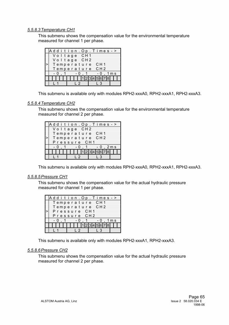
Page 65ALSTOM Austria AG, Linz Issue 2 58.020.034 E
1998-06
5.5.8.3 Temperature CH1This submenu shows the compensation value for the environmental temperaturemeasured for channel 1 per phase.
A d d i t i o n . O p . T i m e s - >V o l t a g e C H 1V o l t a g e C H 2
> T e m p e r a t u r e C H 1T e m p e r a t u r e C H 2- 0 , 1 - 0 , 1 - 0 , 1 m s
1 2 3 4 5 6 7 8L 1 L 2 L 3
This submenu is available only with modules RPH2-xxxA0, RPH2-xxxA1, RPH2-xxxA3.
5.5.8.4 Temperature CH2This submenu shows the compensation value for the environmental temperaturemeasured for channel 2 per phase.
A d d i t i o n . O p . T i m e s - >V o l t a g e C H 2T e m p e r a t u r e C H 1
> T e m p e r a t u r e C H 2P r e s s u r e C H 1- 0 , 1 - 0 , 1 - 0 , 2 m s
1 2 3 4 5 6 7 8L 1 L 2 L 3
This submenu is available only with modules RPH2-xxxA0, RPH2-xxxA1, RPH2-xxxA3.
5.5.8.5 Pressure CH1This submenu shows the compensation value for the actual hydraulic pressuremeasured for channel 1 per phase.
A d d i t i o n . O p . T i m e s - >T e m p e r a t u r e C H 1T e m p e r a t u r e C H 2
> P r e s s u r e C H 1P r e s s u r e C H 2- 0 , 1 - 0 , 1 - 0 , 1 m s
1 2 3 4 5 6 7 8L 1 L 2 L 3
This submenu is available only with modules RPH2-xxxA1, RPH2-xxxA3.
5.5.8.6 Pressure CH2This submenu shows the compensation value for the actual hydraulic pressuremeasured for channel 2 per phase.

Page 66Issue 2 58.020.034 E ALSTOM Austria AG, Linz1998-06
A d d i t i o n . O p . T i m e s - >T e m p e r a t u r e C H 1T e m p e r a t u r e C H 2P r e s s u r e C H 1
> P r e s s u r e C H 2- 0 , 1 - 0 , 1 - 0 , 2 m s
1 2 3 4 5 6 7 8L 1 L 2 L 3
This submenu is available only with modules RPH2-xxxA1, RPH2-xxxA3.
5.5.9 Pressure (L1/L2/L3)This submenu shows the actual measured hydraulic pressure per phase (L1, L2, L3).
M e a s u r e m e n tT e m p e r a t u r e f . C o m pA d d i t i o n . O p . T i m e s - >
> P r e s s u r e ( L 1 / L 2 / L 3 )P r e s s u r e ( L 1 )
3 1 0 3 0 1 3 0 7 b a r1 2 3 4 5 6 7 8
L 1 L 2 L 3
This submenu is available only with module RPH2-xxxA3.
5.5.10 Pressure (L1)This submenu shows the actual measured hydraulic pressure.
M e a s u r e m e n tT e m p e r a t u r e f . C o m pA d d i t i o n . O p . T i m e s - >P r e s s u r e ( L 1 / L 2 / L 3 )
> P r e s s u r e ( L 1 )3 1 0 b a r
1 2 3 4 5 6 7 8L 1 L 2 L 3
This submenu is available only with module RPH2-xxxA1.
5.6 Auxiliary functions
5.6.1 Alarm InputThis submenu is for testing only. It shows the inputs (auxiliary contacts and position ofthe neutral earthing switch) of the alarm-board (only available for module RPH2-xxS).

Page 67ALSTOM Austria AG, Linz Issue 2 58.020.034 E
1998-06
5.6.2 Alarm OutputThis submenu is for testing only. You can set the alarm-outputs individually by typing a‘1’ at the according position of the pattern shown on the display (only available formodule RPH2-xxS).
5.6.3 Error TypeIf an internal fault is detected (selftest interval > 0 h), error flags are displayed in thismenu.
Error type 1: the switching command on input -x8:1 or -x8:6 is still bendingError type 2-4: CH1 phase L1 is defectiveError type 5-7: CH1 phase L2 is defectiveError type 8-10 CH1 phase L3 is defectiveError type 11-13: CH2 phase L1 is defectiveError type 14-16: CH2 phase L2 is defectiveError type 17-19: CH2 phase L3 is defective
5.7 Switching archive
This submenu shows the result of the last 8 switching operations.
List of messages:• Switching OK• NOT Switched (no operation of the breaker)• Command Time min (command impulse to short (<100 ms))
In the statusline the date and the time of the operation is displayed.
Ahead of the messages a reference to the archive entries is shown:"n" last operation"n-1" operation beforeetc.

Page 68Issue 2 58.020.034 E ALSTOM Austria AG, Linz1998-06
6 COMMISSIONING
6.1 Commissioning preliminaries
Before initial operation of a RPH2 Point-on-Wave Controller, time should be taken inorder to become familiar with operation of the device and, if a portable PC is available,with the parameterization software also.
NOTE: After the RPH2 is connected to the supply voltage the first time, or after a selftest, it will last about 20 seconds until the green LED is illuminated and the relay isready for operation (see also 2.4.2.2). If the green LED stays dark, please check atfirst the proper connection of the reference voltage and the neutral earthing switch
6.1.1 Settings
6.1.1.1 Factory SettingsDepending on the model, all values for CB-Data, compensation and all thresholds forthe alarms are set to ‘0’, except:
System Frequency: 50 HzControl Voltage: 125 VSwitching Program: TransformerFunction Cannel 1: CB closingSelftest Interval: 24 hCT Rated Current
primary: 1 Asecondary: 1 A
Alarms:Ref. Voltage Failure -> Alarm1Neutral intermediate -> Alarm2
All other alarm functions are inactive.
6.1.1.2 Necessary SettingsBefore the RPH2 is ready to operate, all relevant settings must be completed. Thesedata must be set before the first operation (depending on the model):
• System frequency (5.1.2)• Control voltage (5.1.3)• Rated pressure (5.1.4)• Switching program (5.1.5)• Function channel 1 (5.1.6)• Operating times of each pole (5.2.1, 5.2.2)• Arcing Times (5.2.3, 5.2.4)• All data for compensation and adaptive control (5.2.7....5.2.16)• Actual control voltage (5.3.4)• Ratings of external transducers (5.3.5, 5.3.6)

Page 69ALSTOM Austria AG, Linz Issue 2 58.020.034 E
1998-06
All other parameters are not essential for operation.
To evaluate the necessary data, use the configuration checklist shown on the lastpages of this service manual.
6.1.2 InspectionCheck whether the external wiring corresponds to the relevant RPH2 wiring diagram.Particularly whether the reference voltage and the neutral earthing switch positionsignals are wired. If a switching of the neutral is not intended, then it is necessary toshort circuit the relevant input terminals of the RPH2 (-X6:8 with -X8:11 for neutralisolated or -X6:8 with -X8:12 for neutral grounded).
Make sure that the case is properly earthed. If external sensors are necessary, theyare to be installed according to the manufacturer's information. Check whether theplug-in unit is sitting firmly and the fixing screws are tightened.
Measure the actual RPH2 control voltage with a multimeter. This value (depending onthe model) is required for parameterization (5.3.4).Check the 48 V field voltage between the terminals -X6:8 and-X6:11 (ground).Measure the voltage at the inputs of the external transducers (approx. 24 VDC).
Compare the displayed values on the RPH2 for control voltage, hydraulic pressure andambient temperature (only models RPH2-xxA) with the externally measured ones.
Verify the connections of the voltage and current transformer circuits (current only formodel RPH2-xI) to the correct terminals (100/√3V or 220/√3V, 1A or 5A) of the RPH2.
The two functions of the menu [Aux. Functions] maybe helpful by testing the externalconnections:
The proper connection of the CB’s auxiliary contacts to the RPH2 (only modelRPH2-Sxx) can easily be checked by the function [Aux. Functions][Alarm Input]. Whenthe circuit breaker is in the closed position you must see three ‘1’ at the first positionsin the status line.
A u x . F u n c t i o n s> A l a r m I n p u t
A l a r m O u t p u tS e l f t e s t E R R O RR P H 2 V 3 . 0 4 1 6 - 0 3 - 9 9
1 1 1 0 0 0 0 11 2 3 4 5 6 7 8
L 1 L 2 L 3
When the breaker is in the open position, three ‘0’ will be displayed.If the remote reset input is activated, at the fourth position a ‘1’ must be displayed.

Page 70Issue 2 58.020.034 E ALSTOM Austria AG, Linz1998-06
By using the function [Aux. Functions][Alarm Output] you can activate individually eachalarm relay by typing a ‘1’ at the according position of the pattern. So the externalwiring of the alarm circuits can be checked on correct function.
6.1.3 First operationWhen all inspections are done, operate the dead circuit breaker via the RPH2. OnPoint-on-Wave-Controllers with option S check, if the measured operating times arecorrect, otherwise adjust the values for [Aux.Timeshift] according to 4.1.2.1. Prove thatthe command impulse to the RPH2 is of sufficient length.
For the first load switchings, we recommend using an oscillograph to measure thecurrents of the three phases together with the reference voltage, in order to verify thatthe unit is working correctly. It is helpful if the three relayed drive commands can alsobe recorded on additional oscillograph traces.
By using a RPH2 with the option I the currents during switching can be displayed andanalysed (see 5.5.1).
If the results are not satisfactory you must adapt the pole operating times and/ or thearcing times to achieve the optimal function.

Page 71ALSTOM Austria AG, Linz Issue 2 58.020.034 E
1998-06
Configuration Checklist RPH2
System Data
System Frequency ΟΟΟΟ 16 2/3 Hz ΟΟΟΟ 50 Hz ΟΟΟΟ 60 Hz
Control Voltage (48V...250V) ........................V
Rated Pressure .........................bar
Switching program: ΟΟΟΟ Transformer ΟΟΟΟ Shunt Reactor ΟΟΟΟ Capacitor Bank
Ο User Program
Point on Wave L1 L2 L3
T_C1 Neutral isolated msT_C1 Neutral grounded msT_C2 Neutral isolated msT_C2 Neutral grounded ms
Function Channel 1 ΟΟΟΟ CB Close ΟΟΟΟ CB Open (RPH2-1xx only)
Language ΟΟΟΟ German ΟΟΟΟ English ΟΟΟΟ FrenchΟΟΟΟ Free language ...................................
Selftest Interval .............Hours
CB Data:CB Data L1 L2 L3
Operating Time CH1 msOperating Time CH2 msArcing Time CH1 msArcing Time CH2 msAux.Timeshift CH1 msAux.Timeshift CH2 ms
Adaptive Control Weighting Factor ....................
Compensation ΟΟΟΟ Yes ΟΟΟΟ No
kU1 Voltage CH1 ....................
kP1 Pressure CH1 ....................
kU2 Voltage CH2 ....................
kP2 Pressure CH2 ....................

Page 72Issue 2 58.020.034 E ALSTOM Austria AG, Linz1998-06
Configuration Checklist RPH2
Temperature Compensation:Switching Channel 1 Switching Channel 2
Analogue Data:Thresholds:
Current max. (peak) .................... A
Control Voltage max ..................... V
Control Voltage min ..................... V
Temperature max .................... °C
Temperature min ..................... °C
Pressure min ..................... bar
Pressure max .................... bar
Actual Control Voltage .................... V (to be measured and set at site)
CT rated current prim. .................... A
CT rated current sec. ΟΟΟΟ 1A ΟΟΟΟ 5A
Temperature:Value at 4 mA ..................... °C
Value at 20 mA ..................... °C
Pressure:Value at 4 mA ...................... bar
Value at 20 mA ...................... bar
Temperature Delta_t+50 °C ms+40 °C ms+30 °C ms+20 °C ms+10 °C ms
0 °C ms-10 °C ms-20 °C ms-30 °C ms-40 °C ms-50 °C ms
Temperature Delta_t+50 °C ms+40 °C ms+30 °C ms+20 °C ms+10 °C ms
0 °C ms-10 °C ms-20 °C ms-30 °C ms-40 °C ms-50 °C ms
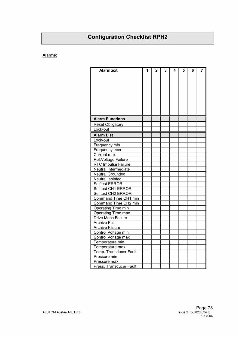
Page 73ALSTOM Austria AG, Linz Issue 2 58.020.034 E
1998-06
Configuration Checklist RPH2
Alarms:
Alarmtext 1 2 3 4 5 6 7
Alarm FunctionsReset ObligatoryLock-outAlarm ListLock-outFrequency minFrequency maxCurrent maxRef.Voltage FailureRTC Impulse FailureNeutral IntermediateNeutral GroundedNeutral IsolatedSelftest ERRORSelftest CH1 ERRORSelftest CH2 ERRORCommand Time CH1 minCommand Time CH2 minOperating Time minOperating Time maxDrive Mech.FailureArchive FullArchive FailureControl Voltage minControl Voltage maxTemperature minTemperature maxTemp. Transducer FaultPressure minPressure maxPress. Transducer Fault