alpha-quartz 3. origin of cellular structure of synthetic quartz
TRANSCRIPT

l~ull. Mater. Sci., Vol. 2, Number 2, May 1980, pp. 91-120. © Printed in India.
Alpha-quartz 3. Origin of cellular structure of synthetic quartz
P R A S E N J I T SAHA and T A R U N B A N D Y O P A D H Y A Y Central Glass and . . . . . . . . . . . . . . . . . . . Jadavptir, ~ . . . . . . . 700 032, ~-~"-
MS received 20 March 1979
Abstract. Surfaces of optically flawless and untwinned quartz single erystals, both natural and synthetic, were dissolved both at room temperature and at high tempe- ratures in autoclaves using appropriate etchants. The features that develop have been optically studied, and x-ray transmission projection topographs of some of the specimens from the same natural quartz were also taken and studied. A model has been proposed to explain the anomalies detected earlier by other workers regard- ing the nature of line defects found in as-grown synthetic quartz, and the absence of lateral strain in the polygonised microcracked layer of the sl~cimens of the present series of experiments.
Keywords. Cellular structure; subgrain boundaries; polygonalisation; frank net; optical twinning; synthetic quartz ; alpha-quartz.
1. I n t r o d u c t i o n
A critical survey and analysis o f x-ray diffraction topographic studies of synthetic quartz, and o f investigations on the nature , concent ra t ion and distr ibution of common impuri ties of na tura l and synthetic quartz carried out by earlier Workers has been made (Sakta et al 1979 ; Saha and Bandyopadhyay , 1979). I t was inferred tha t a major i ty (80-85~0) of the dislocations present in synthetic quartz are cell-wall dislocations, with a predominant ly pure edge, a (11~0), glide componen t operat ing on {10T0} slip planes, the dislocation segments being parallel to the c-axis, and possibly associated with an alternating non-conservative climb componen t alter- nately jogging the dislocation lines so as to allow those submicroscopJcally small segments to make fairly high angle with the c-axis* . I t was also inferred tha t climb is p robab ly caused by precipi ta t ion or cap ture of impurit ies such as hydrogen, alkali hydroxides or H~O f rom the growing medium at suitable defect sites (opened-up discontinuities) o f the structure. The present series o f experiments
* Recently, Barns et al (1978) have pointed out the anomalies in the determinations of Burgers vectors of dislocations in synthetic quartz performed by Lang and Miascov (1967), McLaren et at (1971), and Barns et al (1978) themselves. However, the anomalies were pointed out by one of the authors of the present paper (PS), and the climb mechanism was suggested as well to explain the anomalies, during an invited talk at the National Conference on Crystallography held at Vallabh Vidyanagax, Gujarat, India, during February, 1978.
91

92 Prasenjit Saha and Tarun Bandyopadhyay
were conducted with hoth natural and synthetic quartz to obtain more evidence in support of those inferences, as well as to investigate the absence of strain in synthetic quartz because of the accumulation of impurities that cannot be accom- modated in the ideal structure. The results obtained, along with the inferences drawn from analysis of previous work, have enabled us to propose a phenomono- logical model of defect structures likely to be associated with synthetic quartz, which (i) explains the features distinguishing synthetic quartz from untwinned natural quartz, like concentration of certain impurities far ~n excess of what is required by the chaxge compensation rule, deterioration of mechanical Q with increase in concentration of impurities, etc., and (ii) provides a mechanism for formation of cellular structure in synthetic quartz without causing detectable lateral strain in the lattice.
2. Experimental
Carefully selected optically flawless and untwinned natural quartz single crystal (Indian and Brazilian) were sectioned into plates paraUel to the basal surface, i.e. cut parallel to (0001) with the help of a diamond saw. In the synthetic crystals (obtained from Sawyer Research Products) rods normal to {2IT0}, more commonly known as Y-bar rods*, were selected trom different areas of the bulk crystals and their relative positions with respect to distance from seed plato noted for future reference. The foUowing experiments were performed:
(i) Room temperature (RT) etching of (000J)-cut plate of an Indian natural quartz, using 20~ HF solution (for 2 hr and later, for 20 hr more).
(ii) (a) Hydrothermal dissolution (etching in an autoclave of about 200 co capacity) of five adjacent portions of a (0001)-cut plate of an Indian natural quartz, and another section from an adjacent parallel plate of the same quartz (figure 1), at different temperatures in the range 104 ° C---492° C and duration varying from a maximum of 5 hr to a few seconds. Pressure was kept constant at about 374"25 q- 17"02 atm Etcbant 0.5 M Na~COa. (b) I-Iydrothermal dissolution of a (0001)-cut plate of a Brazilian natural quartz. Temperature 322 ° C; pressure 5,500 psi; duration 75 rain. Etching in approx 200 cc capacity autoclave with 0" 5 M Na~COs q- 0" 07 M LizCO~ solution.
(iii) Hydrothermal dissolution (etching in autoclave of about 6000 cc capacity) of six synthetic Y-bar rods at a pressure of 4400 psi and temperature o f 335 ° C for a few seconds. Etchant 0" 6 M NasCO8 + 0" 05 M LiNe2.
The surface dissolution features were optically examined in a polarising micro- scope, and later projection transmission topographs of the specimens of the (iia) series of experiments were taken. Some of the latter specimens had to be polished and projection topographs taken again to obtain details of the internal (volume) features which axe quite often masked by the surface features, specially for the specimens treated below 200 ° C.
* Y-bar rods fabricated in this manner will honc~.,forth be referred to as seed plates normal to (0001) to facilitate comparison with other (O001)-cut seed plates.

.4lpha-quartz 3.
(a) ~ (g) ~
' If) (b)
(1)
93
(2)
(O001)-cut plotes ~ . 0 c m ; Thickness • 1.8mm(7Omils)
t - - I
Figure 1. Schematic diagram showing the location of (0001)-cut plates of an Indian natural quartz. Dotted portions indicate disposition of the natural rhombohedral faces.
3. Optical microscopy
3.1. RT-dissolution
The as-cut and dissolved surfaces have been reproduced in figure 2. The finely granular as-cut surface (figure 2a) with two small patches of chipping (one of them indicated by an arrow in all the reproductions) revealed surface micro- cracks and opening up of some microcrack crevices after short-time etching (figure 2b). The random orientation of the mierocracks is very obvious hdre. Prolonged etching (figure 2c) removed all traces of the entire damaged surface including the microeracks, and an uneven surface covered with largo triangular etch pits, showing tails indicating the handedness of the crystal, and some triangular pyramids surrounded by ill-defined subgrain boundaries remain.
94 Prasenjit Saha and Tarun Bandyopadhyay
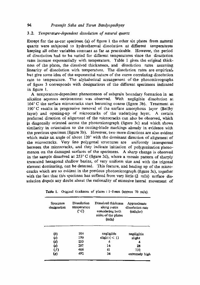
3.2. Temperature-dependent dissolution of natural quartz
Except for the as-cut specimen (a) of figure 1 the other six plates from natural quartz were subjected to hydrothermal dissolution at different temperatures keeping all other variables constant as far as practicable. However, the period of dissolutiou had to be varied for different temperatures since the dissolution rates increase exponentially with temperature. Table 1 gives the original thick- ness of the plates, the dissolved thicknesses, and dissolution rates assuming linearity of dissolution with temperature. The dissolution rates are empirical, but give some idea of the exponential nature of the curve correlating dissolution rate to temperature. The alphabetical arrangement of the photomicrographs of figure 3 corresponds with designations of the different specimens indicated in figure 1.
A temperature-dependent phenomenon of subgrain boundary formation in an alkaline aqueous environment was observed. With negligible dissolution at 104 ° C the surface microcracks start becoming coarse (figure 3h). Treatment at 190°C results in progressive removal of the surface amorphous layer (Beilby layer) and opening-up of microcracks of the underlying layer. A certain preferred direction of alignment of the microcra~ks can also be observed, which is diagonally oriented across the photomicrograph (figure 3c) and which shows similarity in orientation to the cutting-blade markings already in evidence with the previous specimen (figure 3b). However, two more directions are also evident which make an angle of about 120 ° with the dominant direction of alignment of the microcracks. Very fine polygonal structures are uniformly interspersed between the microcracks, and they indicate initiation of polygonisation pheno- menon on the damaged surfaces of the specimens. A sharp change is observed in the sample dissolved at 253 ° C (figure 3d), where a mosaic pattern of sharply truncated hexagonal shallow basins, of very uniform size and with the trigonal element dominating, can be detected. This feature, and healing up of the micro- cracks which are so evident in the previous photomicrograph (figure 3c), together with the fact that this specimen has suffered from very little (2 mils) surface dis- solution dispels any doubt about the rationality of extensive lateral movetment of
Table 1. Original thickness of plates : 1.8 mm (approx 70 mils).
Specimen Dissolution Dissolved thickness Approximate designation temperature along c-axis dissolution rate
(° C) considering both (mils/hr) sides of the plates
(rail0
(b) (c) (d) (e) (f) (g)
104 190 253 297 406 492
negligible slight ( < 1)
4 14 61 34
negiligible slight
4 28
732 extremely high

L 0.
2ram
=
Figu
re 2
. R
oom
tem
pera
ture
etc
hing
of
a na
tura
l qu
artz
cry
stal
on
(00
01)-
cut
surf
ace.
ic
) et
chin
g fo
r 22
hr.
ia
) as
-cut
; ~b
) etc
hing
for
2
hr ;
,o

@
g~
Figu
re 3
. T
emre
ratu
re-d
el;e
nden
t sub
grai
n bo
unda
ry f
orm
atio
n on
hyd
roth
erm
ally
tre
ated
(00
01)-
cut
surf
aces
of
an I
ndia
n na
tura
l qu
artz
sin
gle
crys
tal.

Alpha-quartz 3. 97
dislocations generated in the damaged portions of the crystals introduced exter- nally by cutting. It may, therefore, be surmised that close to this temperature extensive temperature-dependent surficial plastic movement causing surface polygonisation and so.bgrain boundary formation takes place. The very sharp boundaries of the polygons and their similar orientation and alignment suggest tight crystallographic control over lateral movement of dislocations during polygonisation of the surface subgrain boundaries.
At a still higher temperature of 287°C (figure 30, the crystallographically controlled basins, while remaining shallow, broaden out areally (cf. cobble-like elevated features on (0001)-cut surface of grown quartz) and lose their high relief. They are roughly circular to polygonal in outline and of varying size, but the crystallographic control over the alignments of the edges appears to have dimi. nished. The general surface in totality is now covered with a random distri. hution of perfectly circular bubble-lik0 depressions (size range 0"4-0"004 mm dia. ; density 1 "64 × 104cm-~), and they do not seem to be related to the poly- gonal basins. Though this specimen has suffered unidirectional dissolution of 14 mils, some similarity with the 253°C specimen (figure 3d) and complete lack of similarity with the heavily dissolved 406 ° C sample (figure 3 0 suggest that the polygonisation effect is entirely surficial alld plastic flow has persisted only upto the lowest level of the disturbed layer, if such a level cart be dis~ngt~ishod, Below this disturbed layer the crystal will be strained elastically, the magnitude diminishing gradually with depth, on both sides of the (0001)-cut plates.
The 406°C specimen (figure 30 in striking contrast to the proced.ing specimen (figure 30) does not seem to possess any surface relief and the surficial subgrain boundaries of the 287 ° C-specimen type are entirely missing. Instead, faint, widely-spaced subgrain boundaries can be detected. However, bubble-like depressions as found in figure 3f persist here, their density, so far as can be deter- mined, being of sim~,lar magnitude (i.e., 1.60 × 104cm-~). It can therefore be inferred that the s trace disturbed layer has been removed almost completely, artd that the faint suhgrain boundaries are probably the relicts of volume sub- grain boundaries of the natural crystal. At the final stage of dissolution at 492°C (figure 3g) the volume suhgrain boundaries and the bubbleqike depres- sions have become very much fainter, i.e., they can be distinguished only ~vitb an out-of-focus arrangement of the microscope though only a 34,mil thick layer of this specimen has dissolved as compared to a 61-mil thick layer of the previous one (table 1).
The natural Brazil!an (0001)-cut plate of figure 4e, however, shows that high relief and sharp trigonality of the subgrain boundaries are maintained at a tempe- rature as high as 322 ° C in contrast to lack of similar features in the 287 ° C Indian specimen (figure 3o). Moreover, the bubble-like depressions are almost entirely lacking in this sp~imen. The absolute dissolution and dissolution rate of this specimen, however, are comparable to those o f specimen (e) of the 2a series of experiments.
3.3. Temperature-dependent dissolution of synthetic quartz
The diagrammatic sketch of figure 4 shows the locations of the cross-sectional areas of the synthetic Y-bar specimens investigated with respect to the {21-i. 0~-

98 Prasenfit Saha and Tarun Bandyopadhyay
surface of the parent synthetic crystal. The different growtb zones of any Y-bar synthetic quartz and the seed plate on which itis grown areclearly brought out in such type of sketches or topographs (vide, topograph of Takagi et al reproduced:in figure 5 of Saha et al 1979a). It can be seen that specimen marked (1) includes bo th Z-zone and (-- X)-zone of growth, whereas specimens (2) to (6) were extracted ex5lusively from the Z-zones of growth of the mother crystal.
Figure 4a illustrates a portion of the dissolved (0001)-surface of spec;men (1) within t ha tpa r t of the Z-zone whichis normal to the seed-plate area. Parts such as this have been demarcated in the sketch by the two parallel dashed lines skirting the shorter edges of the sectional view of the seed plate.* The shallow surfieial polygonal basins in this case, as in the case of all the synthetic samples dissolved at 335 ° C, are quite similar to those of the natural Brazilian quartz described before (figure 4e), and they are likewise devoid of the bubble-like depressions, found in natural Indian quartz (figure 3e). However, t h e most characteristic feature of this photomicrograph is the presence of very deep coalescing etch pits arraigned in rows and forming a network of widely spaced subgrain boundaries; a few individual deep etch pits are sporadically distributed in the intervening areas. Figure 4b is a photomicrograph of the same (0001)- surface, but now displaced laterally so as to bring the transitional sector between the Z-zone and the (--X)-zone of the mother crystal in the field of vision. The significant features of this figure are (i) the complete absence of the deep etch pits and the network, and (it) the presertce of a straight line boundary demarcating the Z-zone from the (-- X)-zone. Surficial polygonal basins on the straight line do not appear to have been affected to a great extent by the inclined demarcating piano (of which the straight line is the trace on this surface) except for darkening of the polygonal basins on one side.
It has been verified from a study of ma, ny synthetic specimens that the deep etch pits are always confined to those portions of the Z-zones of growth which are normally aligned to the (0001)-cut seed-plate areas of the mother crystals, as has been found in the example cited (figure 4a). Figures 4c and 4d, which are lightly polished opposite (0001)-surfaces of specimen 5, show that the networks formed by the deep etch pits continue through a thickness (after dissolution) of at least 2.286 mrn. From those observations it can be surmised (i) that those etch pits are surface manifestations of dislocations intrinsic in the volume of the mother synthetic crystal, (it) that those dislocations are confined to columnar volumes of the Z-zones of growth overlying the (0001)-cut surfaces of the seed plate of the mother crystal, as found in the projection topographic work of Takagi et al (1974) (figure 5 of Saha et al 1979a), and (rio that those dislocations which are confined to the network are the a-type ceU-waU dislocations identified in topographs o f as-grown synthetic quartz by Lang and Miuscov (1967) and McLaren et al (1971) (Sahae t al 1979a). It may further be noted from figures 4c and 4d that an approximate 120 ° alignment is maintained between the cell-wall boundaries defined by those dislocation etch pits, but that they have become displaced laterally through the thickness of the specimen. The numerical figures accompanying the sketch of figure 4 give the densities of those deep " v o l u m e " etch pits only, of the different specimens. It may he recalled that they are of the same order of magni-
* vide, footnote of page 92.

la)
(b)
(c)
(el
(d)
g 4~
SC
ALE
S
(a),
(b),
(c) & (
d)
i 0.5
ram
,
re)
0.5m
m
I I
_t
-~ +
X-ZON
E ,////
~ S
YN
THE
TIC
O
UA
RTZ
ETC
H P
IT D
EN
SIT
IES
o N i N
{3)
7.8x
102
(4)
8.8x
102
(5)
4.2x
102
(6)
2.9
,, 10
2
(2J
5.9x
102
per
sq.
cm.
Figu
re 4
. H
ydro
ther
mal
di
ssol
utio
n fe
atur
es
on (
0001
)-cu
t su
rfac
es o
f sy
nthe
tic
(a, b
, c
and
d)
and
Bra
zili
an
natu
ral
(e)
quar
tz
sing
le c
ryst
als.
,,o

Alpha-quartz 3. 101
tude (10 z- 103 cm -z) as those of the dislocations found in the topographs of as- grown synthetic quartz by Lung and Miuscov, McLaren et al and Auvray and Regreny (1973)(Saha et al 1979a). However, since the deep etch pits tend to coalesce (figure 4a) our density counts are likely to be approximate. Neverthe- less, they give some idea of the spreading out of the cell-wall dislocation net- work as we move away from the seed plate of the parent crystal.
4. Optical microscopic observations
The as-cut surface of natural quartz shows that a finely granulated surface layer is formed with occasional patches of chipping (figures 2a and 3a). This layer, hut not the chipped blocks, is probably composed of amorphous material (Boilby layer). Both RT-dissolution and high temperature autoclave dissolution show that this layer is comparatively thin (about 2 mils thick on each sawed surface), and except for the chipped areas can be removed easily (figures 2b and 3c). It appears to be underlain by a microcracked layer which is clearly revealed hy RT-dissolution for a short period of time (figure 2b). The unilateral thickness of this layer could not be determined unequivocally but it would be between 20 and 30 mils. Below this microcracked layer the crystal remains strained because of cutting, the magnitude of strain diminishing as we move away from the cut surfaces. These observations are in complete agreement with the mechanism of delayed microcracking of brittle materials at room temperature suggested in literature (Lunge 1974).
Hydrofluoric acid, even in 20yo aqueous solution, being a strong etchant for quartz does not reveal dislocation etch pits. The pits that can be observed in figure 2e, usually at the tip of the triangular pyramids, are therefore dissolution etch pits. The faint subgrain boundaries of the photomicrograph, however, may he relicts of inherent subgrain boundaries* of natural quartz. The microcracked layer underlying the easily removable thin surface layer remains as such during RT-dissolution (figure 2b),~ hut for elevated temperatures begins to open up (due to HT-dissolution) and their preferred directions (possibly due to damage along preferred directions caused by a combination of rotatory and translatory motions of the cutting blade) become very prominent at about 200 ° C (figure 3c). Fine polygonal structures also appear at about 200 ° C (figure 3c), and the micro- cracks heal up completely and extensive polygonised subgrain boundaries develop through localised plastic flow at about 250 ° C (figure 3d). Thus we find evidence of extensive dislocation movement causing plastic flow in the microcracked layer at a temperature somewhere between 200 ° C and 250 ° C and continuing at higher temperatures concurrently with its dissolution, but not at temperatures below
100 ° C. The sufficial polygonal basins of the microcracked layer, which is a ubiquitous
feature of all HT-dissolution experiments in the range 250 ° C-335 ° C carried out on quartz single crystals, whether natural or synthetic, lose their sharp Crystallo-
* A distinction is understood to be implicit in the terminologies "grain boundaries" and "sub- grain boundaries". The former applies to polycrystalline materials and the latter to single crystals.

1~2 Prasenfit Saha and Tarun Bandyopadhyay
graphically controlled outline and high relief even below 300 ° C in some cases (figure 3e), but retain them in the case of others (figures 4a, 4b and 4e) at a tempe- rature as high as 335 ° C. Only in the former case it is associated with circular bubble-like depressions suggesting collapsed vacancy loops through which water vapour has be~n dosorbed (figure 3e). Since this feature has heen found only in flawless clear natural quartz which in most cases is known to contain not more than 55H/10~ Si (see Bambauer's data. on rock crystal given in table 1 of Saha et al 1979b), there seems to he no other way of accounting fcr profusion of' such bubble-like features in hydrothermally treated natural quartz but to postulate that hydrogen from the solvent was entrapped in the microcracked layer at th~ p:)lygon boundaries (discontinuities) during extensive plastic movement and polygonisation of this layer at about 250 ° C. Loss of high relief and diminution of crystallographic control over the outlines of the polygonal basins above 287 ° C (figures 3e, 3f and 3g) but no significant change in the density of the bubble-like features suggests that water vapour and hydrogen impurities were dosorbed at the polygonal boundaries above 287 ° C in this particular case. However, the tempe- rature of onset of this desorption phenomenon varies from specimen to specimen.
In striking contrast to the synthetic specimens, the deep " v o l u m e " etch pits, most of which are high temperature (approx, 335 ° C) surface manifestations of a-type cell-wall dislocations of synthetic quartz, are entirely missing in natural quartz. This itself is a further proof that the network formed by those dislocations is in fact the cellular structure so characteristic of synthetic quartz. Very low density of dislocations in seed plates of natural quartz on which synthetic quartz with cellular structure has been grown, as has been revealed in a topograph of a~-grown synthetic quartz by McLaren et al (figure 7 of Saha et al 1979a),suggests that the polygonal structure whichdeveloped in the 200-250 ° C range on the (0001)-cut and partially dissolved surface of natural quartz is the source of develop- ment of cellular strt,.cture in synthetic quartz grown on such plates, specially since the polygonal structure is retained (figure 4e) on the (0001)-surfaces at usual growth temperatures (300 ° C-350 ° C; see Bandyopadhyay and Saha, 1966; Chakraborty and Saha 1973, 1974). Also, the topograph referred to shows a high corLtrast layer on each of the two (0001)-cut surfaces of the natural seed, suggesting that they are the dissolved remnants of the polygonised microcracked layers just before the onset of growth.
For synthetic quartz seed plates on the other hand, the already existing cellular structure probably takes a more dominant role in propagating the cellular struc- ture in the grown portion, as would be evident in other topographs of as-grown synthetic quartz of MeLaren et al (figures 6a and 6b of Saha et al 1979a), since they show an almost 1 : 1 correspondence between dislocations in the synthetic seed plate and those of the grown portion. It is likely that many of the dislocations generatod in the mierocracked layer of the seed plat¢~ preferentially migrate laterally to the existing cellular structure of the underlying layer during the plastic flow and polygonisation stage.
The fact that all dislocations in the Z-zones of growth of synthetic quartz (etched surface manifestations of which are the deep " v o l u m e " etch pits) are always confined to columnar volumes normally aligned to the (0001)-cut surfaces of the seed plate (figure 4) which also substantiates the topographic work of Takagi et al (figure 5 of Saha et al 1979a), gives support to the postulate that

Alpha-quartz 3. 103
T' ca. 2.0mm I I
(a)
(b)
Figure 5. Transmission projection topographs of specimen (a) of figure 1,

104 Prasenfit Saha and Taruu Bandyopadhyay
SPECIMEN (d) 2 5 3 C - 1 ~
• ~. ;. ~ ~.~S* 0~
i!l f~ ,N ;
El
,0
4 . / * j
- i : / i
1,0ram • J
X-RAY TRANSMISSION PROJECTION TOPOGRAPHY
SIDE 1
NORMAL
1.0 mm I 1
SIDE 2
REVERSE
1.0ram
OPTICAL MICROSCOPY Figure 6. Transmission projection topography and men (d) of figure 1.
optical microscopy of speci-

Alpha-quartz 3. 105
the polygonised microcracked layer of the (0001)-cut surface of the seed plate is the source of development of cellular structure of synthetic quaxtz.
In order to determine precisely the nature of the polygonised subgrain boun- daries on the (0001)-cut and partially dissolved surfaces of specimens of the 2(ii)a series of experiments, they were subjected to transmission projection topographic studies. About two dozens of topographs were taken; however, only some representative topographs have been reproduced in this paper and a few of them compared with the corresponding optical photomicrographs.
5. X-ray transmission projection topography
Figure 5a illustrates an enlarged print of a topograph of as-cut specimen (a) of figure t. Directions of the diffraction vectors, g[10T0] in this case, have been indicated on all such topographs* reproduced in this paper. Figure 5b shows the polished surface of the same specimert (a) taken with the same reflection, that is, with (1050). It would be evident that the surface-cutting blade markings mask the internal features of the specimen, namely, the fault fringes found in natural specimens of quartz by Lung (1967). It would also be obvious from figure 5b that the specimen is singularly free from dislocations.
The upper left photograph of figure 6 is a part of a topograph of specimen (d) of figure 1 after hydrothermal dissolution at 253 ° C for 1 hr. In relation to the diffraction vector of the previous specimen the reflection used in this case would he (1500). It is evident that the internal features are not obscured in this case since the amorphous layer formed on the surface during cutting has already been dissolved away (vide, figure 3d). The sharply defined fault fringes, characteristic of the parent Indian natural quartz from which this and other specimens of this series had been derived, are not seen here. The interference fringes that can be detected and which are parallel to a natural border of the specimen are due to slightly wedge-like shape of the specimen in thickness caused by dissolution. This feature would very much be in evidence in topographs of the highly dissolved specimen (g) to be discussed later. Dislocations are absent as in the previous case, but roughly circular high-contrast features, with a straight or wavy or even zig-zag white line through the middle splitting them into two are sporadically and irregularly distributed all over the specimen. Further magnified photographs of the same selected area of this topograph and of another taken with (0150) reflection have been mounted side by side in the upper right comer of figure 6. It can be seert that the alignment of the white line passing through the middle of the circular b_igh-contrast areas changes with change in direction of the diffrac- tion vector, and is roughly perpendicular to it.
Those peculiar features of the topographs of figure 6 deserve further analysis. They resemble the kinematic direct images of spherical precipitates in thin perfect crystals of silicon [figure 3.15 (d) of Tanner 1976], but with the important distinc- tion that the central white line is not straight. The presence of spherical preci-
* While using the word topograph in this paper it has been our intention to signify enlarged prints of the actual topographs. The magnification of the actual topographs is × 1 (Lang 1959), since the two types of reflections used for this study, namely, {10i0} and {11~0}, are normal to the specimen surface. Further magnification is achieved optically.

106 Prasenjit Saha and Tarun Ban@opadhyay
pitates in our specimens is ruled out because of two reasons, namely (i) those high-contrast circular areas are entirely missing in the topograph of the polished as-cut specimen (figure 5h), and their density is very much less in topographs (figure 7) of the highly dissolved specimen (g), (ii) for the existence of smooth spherical pre2ipitates in highly perfe2t dislocation-free specimens of natural quartz such as ours (figure 5) the central white lines should always be perfectly straight and exactly normal to the direction of the diffraction vector, which is not the case here. It is therefore, our contention that those features are due to local misorientations in the lattice planes caused by high localisod strains in the micro- cracked layer around chipped regions (figure 2). The lower two optical photomicro- graphs of fig~.,.ro 6 of the two sides of the same area of specimen (d) marked out in the topOgraphs and enlarged at magnification similar to that of the two tope- graphs on the top right corner, suggest that some of the polygon clusters of the microcracked layer may correspond to the high-contrast features, since they show higher relief than the background polygons, and may also be misoriented. To quote from Tanner (1976), " 'Pre=ip i ta tes ' seen in art unpolished sample may well he damaged from cutting with a diamond wheel ".
Figure 7 illustrates two topographs of the highly dissolved specimen (g) of figure t after hydrothermal treatment at 492°C for a few seconds (vide, optical photomicrograph of figure 3g). The thickness of the plate has been reduced at the middle to about half of the original thickness (table 1) and preferentially at the edges to g~ve rise to wedge-shaped borders. This has caused closely- spaced Pendell6sung fringes to appear skirting all around the herders of the specimen and the seventh Pendelldsung maximum has given rise to the flat darkened area in the middle of the left-hand topograph. In contrast, we find the sixth Pendelldsung minimum in the right-hand topograph giving rise to a white patch in the middle, and this difference is probably caesed by different types of reftections used for taking the two topographs. Presence of Pendelldsung fringes provides conclusive proof that the parent Indian natural quartz is highly perfect and singularly free from defects, including dislocations (Tanner 1976), other than th~ very much localised planar defects giving r;se to the fault fringes. Also, dynamical black-white image contrasts of some defect clusters are wry much in evidence in the upper right-hand edges of the topographs as occasionally found in thin crystals (Tanner 1976). Fault fringes can also be detected, and a sector of one such planar defect, traversing the mid-section of the topographs, goes oIJt of contrast when the fault vector be:omes exactly perpendicular to the diffrac- tion vector g [2ii0], as also detected by Lang (1967).
6. Discussion
The results of our experiments indicate that while cutting any specimen of a brittle material such as quartz with a diamond hlaxle, a shallow Beilhy layer forms on the sawed surface which can easily he removed by RT-dissolution using a suitable etchant. Underlying this layer would he a region of microcracking followed by a strained portion of the crystal, the magnitude of strain decreasing with increasing distance from the cut surface.
Yield at room temperature of brittle materials by a delayed mechanism of microcra~king below critical fracture stress has already heen emphasis~xl by

Alpha-quartz 3. 107
!°,
t
i
~'~-~" Q ':~" ~ ¢LG " 2.0 m m J ° . ' ~
Figure 7. Transmission projection topographs of specimen (g) of figure 1.
Alpha-quartz 3. 109
Saha et al (1979a). This has also been observed in a semiconductor material, e.g., silicon, below the surface during mechanical polishing (Tanner 1976). Figure 8 is a multiple-cell (0001)-projection of the tetrahedral model of alpha- quartz.* The linked corners of the tetrahedra are the centres of the bridging oxygens, and can therefore be the only places of disruption of either of the two Si-O-Si bonds causing a defect to appear in the ideal tectosilicate structure of alpha-quartz. The dashed enclosures indicate successive concentric columns of increasing diameter of the ideal structure parallel to the c-axis (indicated as (1), (2), (3) and (4) in the figure), where the bonding in the structure will be at its weakest since such boundaries never transgress the fundamental SiO 4 building units. Figure 9 illustrates a conoscopic view of a third of the structure along the c-axis, and column (2) of figure 8 has been indicated as a fence in this figure. Figure 10 gNes the data on oxygen density on the surfaces of those cylindrical columns. It is highest for column (1), drops sharply to the lowest value for column (2), and then increases exponentially for successive columns, attaining an almost steady value of 8.55 × 1014 cm -2 for column (30). If a sufficiently narrow hole in the atomistic scale and parallel to the c-axis can be physically punched in the structure, it is likely that the material enclosed in column (2) would be displaced, by gliding along the column surface and therefore in the c-axis direction (eft pencil glide in b.c.c, iron), since bond density, depending on oxygen density, would be lowest on the surface of such a column. However, this is an impracticable proposition, and what we find in reality are curved micro- cracks below critical fracture stress and macroscopic "concho ida l " fracture above, caused by propagation of the microfracture over the curved surfaces of the different columns. This is, of course, a very much simplified model of the mechanism of "conchoida l" fracturing of quartz, and the structure will have to he considered in three-dimension to substantiate the model proposed.
The glide directions of the a (11~0) cell-wall dislocations found in synthetic quartz have also been indicated in figure 8. Since these were also identified as pure edge dislocations (vide, Saha et al 1979a), glide associated with them should be on {10T0} planes for the dislocation lines to be parallel to the c-axis. How- ever, it can be seen from figure 8 that there is no smooth planar surface in those dir~tions, and alignment of such " p l a n e s " in the tetrahedral model, which should have the least density of the bridging oxygen atoms, must necessarily have a sawtooth-like appearance due to the projecting corners of the SiO 4 tetra- hedra. The oxygen densities on those serrated {10TO.} planes, (i) considering the additional lengths due to the sawtooth projections, and (ii) without considering them, hg.ve been indicated by the two horizontal lines in figure 10. It can be seen that though oxygen density of such a serrated plane considering the saw- tooth projections [horizontal line marked (b) in figure 10] is as low as the oxygen density of column (2), glide would be impossible because of the serrations.
Figure 11 shows superposition of the structure of alpha-quartz on the structure of beta-quartz in (0001)-projection after ignoring the cumulative effect of volume expansion at the transition temperature (573 ° C). It would be obvious that for
* All diagrammatic sketches of alpha-quartz of this paper refer to the P3z21 enantiomorph, unless stated otherwise.

110 Prasenjit Saha and Tarun Bandyopadhyay
[11201 111201
Figure 8. Multiple-cell (0001)-projection of the tetrahedral model of alpha-quartz. The large dots indicate the position of the silicon atoms at the centres of the tetra- hedra.
hera-quartz the sorrations would not be present on the {10i0} glide surfaces. It is therefore, easy to visualise exterts'_ve a-type pure edge dislocation movement in beta-quartz at room temperature, had it been possible to retain the structure below 573 ° C. I n contrast, extensive movement of such dislocations in alpha-quartz appears to be a physical impossibility.
Temperature-dependent plastic flow in the microcracked layer, as observed in our experiments, can therefore be visualised as due to movement of a-type pure edge dislocations generated in the microcracked layer on smoothened-out {10i0} glide planes, the smoothening-out process having been caused by.enhanced thermal vibration of the bridging oxygen atoms on such "serrated planes" at elevated temperatures.
The most startling feature of optical microscopic and transmission projection topographic studios of our experimental work is the fact that the network of poly-

Alpha-quartz 3.
I,
,%
1tl
j I I
1 I I
"O
oSi, oO
-).
Figure 9. Partial conoscopic view along c-axis of the sphere-model structure of alpha-quartz ; only a third of the structure has been shown.
gons so prominent on the exposed surfaces of the microcracked layers of specimen (d) under the microscope is totally absent in enlarged prints of the corresponding topographs at similar magnification (figure 6). The topographs were taken on an Ilford G5 nuclear emulsion plates having an emulsion thickness of 50 p, at the research laboratory of M/s. Rigaku Denki, Japan, with their cameras usingAgKax radiation. For such high precision work, it has been estimated that vertical resolution would he of the order of 1/z and horizontal resolution about 6/t (Yoshimatsu 1968). Perhaps it would have heen hotter to use L4 nuclear emul- sion plates (Tanner 1976) to reduce the grainy hackground evident in the tope- graphs (figures 5, 6 and 7), hut since b = 4.9 A for a-type pure edge unit dislocations in atplm-quartz, A0, being approx. 5 × 10 -5 radians for the low order reflections t ~ d , namely, {10i0} and {t1~0,}, it can he calculated that r, the effective radius of

119-
001 --9.0- E tA
v-- C ) ,¢...
X
) . .
w 0 3
z BO. ttl
z ttl >- x o
7.0-
Prasenfit Saha and Tarun Bandyopadhyay
~ -.-------..---0~
{Io~o} ( e l . . . . . ~ , . , . , ~ e . . . . . . . o.~-.~...
11070} - ' ~ - ~ (b). . . . . . . . - , . . . . . . . . ~ . - . . . .
6.77
' ' ' (2 'o ) oh) NUMBER OF COLUMN
Figure 10. Oxygen densities of the surfaces of the concentric columns of weak zones in the structure of alpha-quartz of figure 8 and of the {IOTO} serrated surface.
the strain field around the core of the dislocation where intensity or contrast will be enhanced would be approx, b/AO~, or, about 10p (Yoshimatsu 1968). Thus it would be expected that the experimental technique should resolve individual disloca- tions. Moreover, the average diameters of individual polygons of specimens (d) and (e) being 0.07 mm and 0.13 ram, or 70 g and 130/z, respectively, had the boundaries of the polygons been associated with strain fields of the postulated a-type dislocations the networks of the exposed polygonised surfaces of the micro- cracked layers on the two sides of the specimens should have been observed in the topographs, as in the case of the high-contrast roughly circular features of figure 6. Overlap of the networks of the top and bottom surface, however, could have

Alpha-quartz 3. 113
% S
d
! t SOLID LINES i , SOLID LINES O~-QUARTZ ~ /~ -QUARTZ
[1120]
Figure 11. Tetrahedral model of structure of alpha-quartz superposed on the struc- ture of beta-quartz (dotted tetrahedra) in (0001)-projection after ignoring the cumulative effect of volume expansion.
made recognition of individual polygons in the topographs difficult. Absence of imagos of the polygons in the topographs of figure 6 therefore indicates that no lateral strain is associated with them, and any theory aimed at correlating this polygon~sed layer to the development of cellular structure in synthetic quartz must account for absence of lateral strain in this layer, and this has heen attempted in the model that is going to be proposed now.
7. Proposed model on the origin of cellular structure in synthetic quartz
Introduction of even a single pure unit a-type edge dislocation in the ideal struc- ture of alpha-quartz without causing appreciable lateral strain and total disruption of the lattice is a physica ! impossibility, even if a Frank net type of dislocation arrangement with 2~ b, = 0 (Cottrell 1964), is proposed; this has been investi-
m

114 Prasenfit Saha and Tarun Bandyopadhyay
lh=~!a[21:01
!
'"-
(o1~o1
\
Figure 12. Proposed model of subgrain boundary (Frank net) formation on the (000t)-cut surface of synthetic quartz.
gated exhaustively by the authors and can be verified by construct ing the appro- priate models. The only alternative seems to be what has been depicted diagram- matically in figure 12. This is a tetrahedral model of the s t ructure of alpha- quartz with a nodal point of the Frank not at the centre. Three a-type "pa r t i a l s "* meet at each nodal point, so that ~ b, = 0, with n = 3. The half-planes of the
11
partials, operat ing on {10i0} slip planes, radiate out f rom the nodal point and are disposed in such a manner tha t the zones of compression and tension o f each of the three partials alternately overlap at the nodal point , and the resultant or residual strain at the core (nodal point) is reduced to zero. The line o f the dis- location would therefore be in the direct ion of c-axis emerging outwardly from each nodal point. Concurrent dissolution during polygonisat ion ofmicrocraeks
* The mechanism of glide movement suggested hero prior to formation of Frank not has some of the propextios of true partials ; however, twin element component of tb_o half-planes distin- guishes them from true partials. This fact should be clearly understood even though we have reYe, rmd to th~a as partials in later discussions.

Alpha-quartz 3, 115
due to movement of the partials may have been the reason for opening up of the strueture at the half-planes avd at the nodal points along the c-axis. Complete specifications of the partials would be ~ a (1120) {10T0.}. However, the partials themselves would not account for the absence of lateral strain. For this it has been necessary to postulate optical twinning o~ atomistic scale caused by intro- duction of a single row of oppositely oriented SiO4 tetrahedra [overlapping in (0001)-projection] in each half-plane at suitable intervals. The half-planes would therefore consist o f two parallel, but linked components, namely, a plane of oppositely oriented SiO 4 tetmhedra and a plane of normally oriented SiO4 tetra- hedra (figure 12). Thus, in terms of the mnemonic proposed by Saha et al (1979a), the oppositely oriented totrahedra would be disposed in the manner of the tetrahedra of the P3121 enantiomorphic form of alpha-quartz (striped tetra- hedra of figure 12) in a basic P3~21 lattice (see figure 3 of Saha et al 1979a). It would be evident from figure 12 that the materials between the half-planes of the lattice are good compact materials, and do not cause any lateral strain to the lattice.
In our opinion, the following are the supporting features of this model: (i) Extensive plastic flow in the microcracked layer can be visualised at elevated
temperatures, prior to the formation of the Frank net. The Frank net essentially pins the partials and prevents glide movement. This may account for the absence of dislocations characterised by deep volume etch pits under the optical micro. scope in regions outside a columnar volume in the Z-zone of growth overlying the (0001)-cut seed surfaces (figure 4).
(ii) The zone between microeracked layer and the underlying strained but not cracked layer is the place for embryonic stage of formation of half-planes contain- ing the twin elements. This region would therefore be strained in projection. Hence with suitable reflections this region would show ttp as a region of contrast on the (0001) seed surfaces of synthetic quartz. This has been found in the works of Takagi et al and McLaren et al (see figures 5, 6 and 7 of Saha et al 1979a).
(iii) This model also provides for broken bonds at the half-planes and at the nodal points. Unsaturated oxygens here become the likely places for absorp- tion of hydrogen impurity independent of the aluminium impurity content of the crystal, as found in synthetic quartz (Saha and Bandyopadhyay 1979b). Figures 13 and 14 show the method of formation of free O - H groups at the nodal points and at the half-planes. Figure 14b gives their elevation around a hole generated in th© half-plane. Only one complete spiral turn of SiO~ t©trahodra along tke a-axis has been considered. It cart be seen that even with id©al configuration of the tetrahedra each containing a free O-H group, the protons of the two neigh- bouring groups just touch each other. Proton-proton repulsion will of course leer©use this distance and those tetr~hedra may bond fv+rther+ The environment of ~,eh f r ~ O--H .group b©ing similar the force constants associated wi th ~ e m ar~ likely to be, the sam e, and the O--H absorption bands that should be obs~rvabl¢ should therefore overlap at the same wave aural)or (Rue" 1963). The very characteristic band of ~yntheti¢ quartz at 359.0 cm -~ at room temperature shifted to 3585 cm -a at 78 K, has never been observe~ in natural quartz, am! has probably arisen from the above type of mechanism. The free O~H groups of our med~l, without oonsidering the proton-proton re?ul~on, would make anllles of 6~ ° 30, and of 42 ° 18' with the c-axis. However, the actual valt,.© obtained would be about

116 Prasenjit Saha and Tarun Bandyopadhyay
H20- oO /
I
i !
i J
I
Figm, e 13. Sphere model representation of the opened-up c-axis channel at the nodal points of figure 12. Absorptions of proton at the unsaturated oxygen bond to form free O-H groups have been indicated here. The small black spheres repre- sent silicon atom of those broken bonds. The dot-dashed lines indicate orienta- tions of the Si-O-H bonds in plan. True scale dimension of an HsO molecule has been shown in the upper left-hand comer.
73~30 ' (polarisation factor = S.S with a scatter o f 0 .9 , Chakrabor ty 1977). I t is difficult to assess the effect o f p ro ton-pro ton repulsion, and presence of o the r impurities in the c-axis channels, on the or ientat ion o f free O - H bonds at the half-planes and a t the nodal points a t this stago~
(iv) This model also explains satisfactorily the presence o f water molecules giving a b road underlying absorp t ion band in the IR spectrum, and o f alkali hydroxide molecules, in synthetic quartz since figure 13 shows tha t there is enough space loft, even af ter the fo rmat ion of - the free O - H groups, fo~ absorp t ion o f water molecules in the structure;

(2:
Figu
re 1
4.
I /'
@~
|
~
f
Y
Dis
posi
tion
of t
he f
ro~
O-H
gro
ups
at t
he o
pene
d-up
c-a
xis c
hann
els
alon
g th
e ha
lf-pl
anes
; (a
)pla
n.
! i ! ! I
,I ! I i i
{b) e
leva
tion.

118 Prasenjit Saha and Tarun Bandyopadhyay
(v) Though the Frank net pins the glide component in lateral directions, climb can occur during growth in the vertical direction due to absorption of impurities mentioned above, giving rise to lateral shifting of the boundaries of Frank net on submicroscopic scale, and causing the cell-wall "d i s loca t ion" lines to be confined within a cone of 25 ° around c-axis.
(vi) This model also suggests that the Frank net of half-planes, when extended upwards into the Z-zone of growth, forms the network of ceil-walls characterisirtg the cellular structure of synthetic quartz. The 120 ° disposition of the rows of deep etch pits found in synthetic quartz (figure 4c) is in support of this conten- tion, since the half-planes of the model (figure 12) are also oriented at 120 ° to each other. However, lateral shifting of the cell-walls by climb due to incorpo- ration of impurities complicates matters, and the cell-wall boundaries more often than not are not so well-oriented as in figure 4e. Also, since impurities cart be incorporated at opened-up places of the structure at the half-planes and at the nodal points, they can give rise to the imperfect thin layers at the cell-walls caused by segregation of impurities, as suggested by Lung and Miuscov (Sahaet al 1979a). Homma and Iwata (1973) also found concentration of some impurities at the cobble grooves of (0001)grown surfaces of synthetic quartz in their EPMA studios; inhomogeneous distribution of hydrogen impurity, however, will not be revealed by this te:hnique. Also, the fault vector at the cell-walls according to our model would be equal to the Burgers vector of the partials, that is, ¼a or 3.74 A, which is of the same order of magnitude as the fault vector. (1A) estimated by Lang and Miuscov ( S a h a e t al 1979a).
The main disadvantage of this model is that we have to assume edge-sharing of the oppositely oriented tetrahedra at the half-planes along two edges, a feature not found in the crystal chemistry of any silicate structure. While determining the structure of cancrinite Jarchow (1965), however, found instances of one edge sharing. Nevertheless, it can be mentioned here that for optical twinning in quartz, where the twinning plane is {1120} (Saha et al 1979a), edge-sharing seems to be the only mechanism by which it can form, and the lamellae of such twinning are usl,.ally extremely fine in appearance.
8. Conclusions
Some dissolution experiments were conducted with (0001)-cut seed plates of natural and synthetic quartz single crystals at room temperature and at high temperatures (approx. 100 ° C-500 ° C) in autoclaves, and the specimens were oxamined optically and by x-ray transmission projection topography.
RT-dissolution with even 20% aqueous HF solution being comparatively fast and non-s01ective for short-time etching, does not reveal dislocation etch pits, and with long-time etching dissolution etch pits rather than dislocation pits become prominent. On the other hand, HT-di~olution at progressively increasing temperature reveals the following interesting features, among others, lander the optical microscope:
(i) Removal of surface Beilby layer, and simultaneous coarsening and opening up of the microeracks of the underlying layer at about 200 ° C; those two layers constitute the damaged portion of the crystals, damage having been caused b3f cutting.

Alpha-quartz 3. 119
(ii) Formation of t iny isolated polygons between the microcraeks at about 200 ° C, and e~tensive plastic flow and formation of polygonal dopressiom defining subgrain boundaries in ~be microcracked layer around 250 ° C.
(iii) Loss of relief of the polygonal suhgrain boundaries at about 285°C in some natural specimens concurrent with increase in dissolution rate; however, in some other natural specimens and in synthetic quartz sharp relief is maintained at a temperature as high as 335 ° C.
(iv) A network of deep coalescing dislocation etch pits in the Z-zone of growth of synthetic quartz only, restricted to a columnar volume overlying and normal to the natural or synthetic (0001)-cut seed plate area.
From a critical analysis of the above features and of previous work it was concluded that the polygonised subgrain boundaries of the microcracked layer of the seed plate are the source of development of cellular structure of synthetic quartz. Whereas for natural quartz seed plates this seems to be the only source. for synthetic quartz seed plates the existing cellular structure of th,- seed probably plays a more dominant role in propagating itself during lateral growth.
Since earlier topographic work had revealed that the cell-wall dislocations of as-grown synthetic quartz have the character of pure a-type eAge dislocations, plastic flow observed in the microcracked layer at c lea ted temperatures was analysed in terms of movement of edge dislocations. It was concluded that enhanced thermal vibration of the bridging oxygen atoms at elevated temperatures facilitates movement of edge dislocations generated in the microcrackcd layer along {1010} slip planes in {11~0.} directions.
Transmission projection topographic studies of some of the dissolved natural specimens, however, failed to reveal images of dislocations which gave rise to the polygonal subgrain boundaries. This was interpreted to he due to absence of lateral strain in the specimens which, except for the damage caused by cutting, w~¢ found to he highly perfect.
A model has been proposed to account for the ,~bsenco of lateral strain. According to this model three 'partials' which can he characterised as b - -~ a (11~0) {1010}, me~.t at nodal points to give rise to a Fr~mk net, with ~ b~ = 0 (n = 3). The
n
distinctive feature of those "par t ia l s" is the presence of an optical twin element in the half-plaxtes. The cell-wall "dislocation " lines emerge outwardly from each nodal point of the Frank net in the direction of the c-a~ds.
It has been possible to explain many of the peculiar features of as-grown synthetic quartz with the help of this model, e.g., fanning out of the pure a-type edge dislocation lines of the cell-walls into a cone of 25 ° around the c-axds, occur- fence of stacking fault type of planar defects at the cell-walls, presence of hydrogen and alkali impurities in excess of what is required for charge compensation, and ubiquitous association of a broad underlying isotropic band with the sharp anise- tropic OH absorption bands even in the low-temperature infrared spectrum. However, the main difficulty of the model is that a plane of oppositely oriented $iO 4 tetrahedra, sharing two edges with neighbouring normally oriented tetra- hedra, has boon assumed as one of the two components of the half-planes, and this kind of double edge-sharing is unknown amongst silicate structures.

120 Prasenfit Saha and Tarun Bandyopadhyay
Acknowledgements
The authors are indebted to the Director, CGCRI, for his kind permission to publish this paper. The wholehearted cooperation of M/s Rigaku Denki, Japan, in taking the x-ray transmis3ion projection topographs of the second series of experiments at their research laboratory at Tachigawa. Japan, during the visit of one of the authors (Pff) to Japan in 1970 on a JSPS fellowship is gratefully acknowledged. Special thanks are due to Dr M Yoshimatsu, Research Director, Dr H .Maruyama, Miss Takada of the research staff, and Mr S Ishiyama, Mr M Kuboya and Mr Y Nakajima of the administrative staff of M/s Rigaku Denki.
References
Auvray P and Regreny A 1973 Bull. Soc. Fr. Mineral Crystallogr. 96 267 Bandyopadhyay T and Saha P 1966 Bull. Cent. Glass Ceram. Res. Inst. 13 59 Barns R L, Freeland P E, Kolb E D, Laudise R A and Patel J R 1978 J. Cryst. Growth 43
676 Chakraborty D 1977 On the influence of environmental parameters on growth and properties of
quartz single crystals, Ph.D; Dissertation, Jadavpur University Chakraborty D and Saha P 1973 Indian J. Tech. 11 127 Chakraborty D and Saha P 1974 Indian J. Phys. 48 439 Cottrell A H 1964 Theory o f crystal dislocations (New York : Gordon and Breach) Hotnma S and Iwata M 1973 J. Cryst. Growth 19 125 Jarchow O 1965 Zeit. Krist. 122 407 Lang A R 1959 Acta Crystallogr. 12 249 Lang A R 1967 Prec. Int. Conf. on Crystal Growth ed. H S Peiser (Oxford : Pergamon Press) Lang A R and Miuscov V F 1967 J. Appl. Phys. 38 2477 Lange F F 1974 Fracture mechanics o f ceramics Vol. 1. Concept, flaws and fractography (New
York and London : Plenum Press) McLaren A C, Osborne C F and Saunders L A 1971 Phys. Status Solidi A4 235 Rao C N R 1963 Chemical applications o f infrared spectroscopy (New York : Academic Press) Saha P, Annamalai N and Bandyopadhyay T 1979 Bull. Mater. Sci. 1 15 Saha P and Bandyopadhyay T 1979 Bull. Mater. Sci. 1 79 Takagi M, Mines H and Sate M 1974 J. Cryst. Growth 24 & 25 541 Tanner B 1976 X-ray diffraction topography (Oxford : Pergamon Press) Yoshimatsu M 1968 X-ray diffraction micrography--The Lang method (Tokyo : Rigaku Denki)