allpixa camera | manual
TRANSCRIPT
allPIXA camera | Manual
CD40067 R04
2018-07-12

CD40047_R04_allPIXA_User-Manual.docx 2
Table of Contents
1 General Information ....................................................................................................................... 8
1.1 About Chromasens ................................................................................................................... 8 Contact information............................................................................................................ 8 Support .............................................................................................................................. 8
1.2 Firmware and software version in this manual ......................................................................... 9 1.3 List of abbreviations .................................................................................................................. 9 1.4 Definitions ............................................................................................................................... 10 1.5 Scope of supply of the allPIXA camera .................................................................................. 11 1.6 Information about CST ............................................................................................................ 11 1.7 Design of a line scan camera system ..................................................................................... 12
2 allPIXA camera - overview .......................................................................................................... 13
2.1 allPIXA camera highlights ....................................................................................................... 13 2.2 Technical data ......................................................................................................................... 14 2.3 Mechanical dimensions of the allPIXA camera....................................................................... 15
Mechanical dimensions of the allPIXA camera up to 4,096 pixels .................................. 15 Mechanical dimensions of the 7,300 pixel allPIXA camera ............................................. 16
2.4 Ambient conditions .................................................................................................................. 16
3 Safety............................................................................................................................................. 17
3.1 Depiction of safety instructions ............................................................................................... 17 3.2 Basic safety regulations .......................................................................................................... 17 3.3 Safety instructions on the allPIXA camera .............................................................................. 18 3.4 Purpose / applications ............................................................................................................. 18 3.5 Staff requirements ................................................................................................................... 19 3.6 Organisational measurements ................................................................................................ 19 3.7 Safety instructions for maintenance / cleaning ....................................................................... 19
4 allPIXA camera - Design and functions ..................................................................................... 20
4.1 Basic design of the allPIXA camera ........................................................................................ 20 4.2 Design of the allPIXA camera line scan sensor ...................................................................... 21 4.3 Sensor allignment and orientation .......................................................................................... 22 4.4 The allPIXA camera line scan sensor readout principle ......................................................... 23 4.5 Spectral sensitivity of the allPIXA camera line scan sensor ................................................... 23 4.6 Image processing .................................................................................................................... 24
Analog / digital image processing .................................................................................... 24 Image information output on the CameraLink ................................................................. 26
4.7 Black-level correction and shading (flat-field) correction ........................................................ 28 4.8 Image mode ............................................................................................................................ 29 4.9 Monochrome image acquisition .............................................................................................. 29 4.10 White balancing with a closed-loop control ......................................................................... 30 4.11 Setting concept .................................................................................................................... 31
Restore factory default..................................................................................................... 31
5 allPIXA camera - Connections and status LED ......................................................................... 32
5.1 Status LED .............................................................................................................................. 32

CD40047_R04_allPIXA_User-Manual.docx 3
5.2 Power supply .......................................................................................................................... 33 5.3 Config UART (serial RS 232) .................................................................................................. 33 5.4 Digital IO port .......................................................................................................................... 34
LVCMOS and RS422 levels ............................................................................................ 35 5.5 Video CameraLink port 1 ........................................................................................................ 35 5.6 Video CameraLink port 2 ........................................................................................................ 36 5.7 Optical accessories ................................................................................................................. 37
Lenses and mounts ......................................................................................................... 37 Accessories for 7,300 camera W-Series: ........................................................................ 39 Accessories for 2,048 & 4,096 camera S-Series: ............................................................ 40 Mounting of the extension tube systems ......................................................................... 41 Mounting of a lens adapter ring ....................................................................................... 42
6 Getting started .............................................................................................................................. 43
6.1 Pre-setup................................................................................................................................. 43 6.2 Application Setup .................................................................................................................... 43 6.3 Setting the system into operational state ................................................................................ 44 6.4 Adjusting the camera settings to your operating condition ..................................................... 44 6.5 Digital processing and digital line trigger ................................................................................ 46
7 Installing the allPIXA camera ...................................................................................................... 47
7.1 Mechanical installation ............................................................................................................ 47 7.2 Thermal links / cooling ............................................................................................................ 47 7.3 Preventing installation errors .................................................................................................. 47
Conveyor belt tracking ..................................................................................................... 47 Perpendicularity of the sensor to the direction of transport ............................................. 48 Rotation around the longitudinal axis of the line scan sensor ......................................... 48 Rotation around the transverse axis of the line sensor ................................................... 49 Alignment of the allPIXA camera ..................................................................................... 50
7.4 Electrical installation ............................................................................................................... 51 7.5 Connecting the camera to the PC ........................................................................................... 52
8 Installing the Camera Setup Tool (CST) .................................................................................... 53
8.1 System Requirements ............................................................................................................. 53 8.2 Installing the CST Software .................................................................................................... 53 8.3 Establishing communication between camera and PC .......................................................... 55
9 CST program window .................................................................................................................. 57
9.1 Toolbar .................................................................................................................................... 57 9.2 CST menu bar ......................................................................................................................... 59 9.3 Basic camera parameter settings (overview).......................................................................... 61
Camera parameters ......................................................................................................... 61 Image parameters ............................................................................................................ 65 Special functions .............................................................................................................. 67 General information ......................................................................................................... 68 Global parameters ........................................................................................................... 68
9.4 Opening serial connection to a camera .................................................................................. 69 9.5 Transfering data to the camera ............................................................................................... 69 9.6 Saving data to the camera permanently ................................................................................. 70 9.7 Refreshing data from the camera in CST ............................................................................... 70 9.8 Selecting a setting on the camera .......................................................................................... 71

CD40047_R04_allPIXA_User-Manual.docx 4
9.9 Saving settings to the PC........................................................................................................ 71 Saving settings from CST to hard disk: ........................................................................... 71 Saving settings from the camera to hard disk: ................................................................ 71
9.10 Transferring saved settings from the PC to the camera ..................................................... 72 9.11 Deleting settings on the camera .......................................................................................... 73 9.12 Line trigger and encoder settings ........................................................................................ 74 9.13 IO configuration ................................................................................................................... 74
Encoder - enable increments setting ............................................................................... 75 9.14 Setting the user level in CST ............................................................................................... 76 9.15 Resetting the camera .......................................................................................................... 76 9.16 Checking the camera state ................................................................................................. 77 9.17 Edit color conversion (correction) matrix ............................................................................. 77 9.18 Choosing a different configuration file for the parameter display ........................................ 78 9.19 Register Edit ........................................................................................................................ 79
10 allPIXA setup ............................................................................................................................. 80
10.1 Simple setup for a fast ready-to-operate state .................................................................... 80 10.2 Performing a white balancing on the camera ...................................................................... 84
Setting the operation point automatically......................................................................... 84 Setting the operation point manually ............................................................................... 86
10.3 Performing a tap balancing ................................................................................................. 93 10.4 Generating black (offset) reference ..................................................................................... 94
Loading a reference image from disk .............................................................................. 95 Preparing the camera to acquire a raw reference ........................................................... 98 Creating a black-level reference internally .................................................................... 102
10.5 Generating shading/flat-field reference ............................................................................. 104 Loading a reference image from disk ............................................................................ 106 Preparing the camera to acquire raw image ................................................................. 111 Creating a white (gain) reference internally ................................................................... 118
10.6 Using continuous white control ......................................................................................... 122 Continuous operating point adjustment at the edges .................................................... 122 Image-synchronous operating point adjustment on the object (ROI) ............................ 124
10.7 Updating the firmware of the allPIXA camera ................................................................... 126
11 Camera parameters ................................................................................................................ 131
11.1 Integration time parameters .............................................................................................. 131 Integration time .............................................................................................................. 131 Use line period ............................................................................................................... 131 Line period time ............................................................................................................. 132
11.2 Gain settings ..................................................................................................................... 132 Analog coarse gain ........................................................................................................ 132 Current camera gain values .......................................................................................... 133 Camera startup gain values ........................................................................................... 133 Store White balancing parameter .................................................................................. 134 Copy White balancing parameter .................................................................................. 134 Update camera startup gain values ............................................................................... 135
11.3 White reference mark ........................................................................................................ 136 Position and size in CCD direction ................................................................................ 136 Position and size in transport direction (sync. mode) .................................................... 137 First relative pixel of white reference ............................................................................. 137 First absolute pixel of white reference ........................................................................... 138

CD40047_R04_allPIXA_User-Manual.docx 5
Use absolute horizontal position of white reference ...................................................... 138 Number of pixels for white reference ............................................................................. 138 First image line for the white reference ......................................................................... 139 Number of image lines for the white reference .............................................................. 139 Number of reference samples (Average) ...................................................................... 139
Show white reference border ..................................................................................... 140 11.4 White control ..................................................................................................................... 140
Target white reference values ....................................................................................... 140 Current white reference values ...................................................................................... 141 Enable continuous white control .................................................................................... 141 Position and mode for white reference mark ................................................................. 142 White control mode ........................................................................................................ 142 Gain control stop factor ................................................................................................. 143 Set gain control stop by variance .................................................................................. 144 Select active channels for white control ........................................................................ 144
11.5 Reference usage ............................................................................................................... 145 Black-level (offset) correction ........................................................................................ 145 Black reference data set ................................................................................................ 145 White-level (flat-field) correction .................................................................................... 146 White reference data set ............................................................................................... 146
11.6 Brightness and contrast .................................................................................................... 147 Use brightness and contrast .......................................................................................... 147 Brightness ...................................................................................................................... 147 Contrast ......................................................................................................................... 148
11.7 Camera arrangement ........................................................................................................ 149 Set RGB line distance.................................................................................................... 149 Set scan direction .......................................................................................................... 151 Enable suppression of lines/frame due to encoder direction......................................... 152 Mode of lines/frame suppression ................................................................................... 153
11.8 Image Sizes ....................................................................................................................... 153 Number of scan lines per image .................................................................................... 153 Image start delay (lines) ................................................................................................ 154 Scan line length ............................................................................................................. 155 Horizontal binning .......................................................................................................... 156 Number of suppressed lines .......................................................................................... 156
11.9 Synchronization (frame synchronization) .......................................................................... 157 Triggered frame scan..................................................................................................... 157 Scan lines after stop ...................................................................................................... 159 Stop after maximum number of lines ............................................................................. 160 Maximum number of scan lines ..................................................................................... 160 Internal frame trigger ..................................................................................................... 161
11.9.5.1 ROI start ............................................................................................................................... 161 11.9.5.2 ROI length ............................................................................................................................ 162 11.9.5.3 Rising level ........................................................................................................................... 162 11.9.5.4 Falling level .......................................................................................................................... 162 11.9.5.5 Color channel ....................................................................................................................... 163 11.9.5.6 ROI visible ............................................................................................................................ 163
Input debouncing speed (Frame trigger) ....................................................................... 164 Scan pattern .................................................................................................................. 164 Master/slave .................................................................................................................. 166
11.10 Image processing .............................................................................................................. 169 Mirror image horizontally ............................................................................................ 169 Swap red and blue color channel ............................................................................... 170

CD40047_R04_allPIXA_User-Manual.docx 6
Gamma correction ...................................................................................................... 170 Color conversion matrix ............................................................................................. 171 Select active CCM ...................................................................................................... 171 Use keystone correction ............................................................................................ 172 Pixel shift for correction .............................................................................................. 173 Keystone correction width .......................................................................................... 173
11.11 Output format .................................................................................................................... 174 Video output mode ..................................................................................................... 174 Color weights ............................................................................................................. 174 CameraLink connection speed .................................................................................. 175 Type of CameraLink interface .................................................................................... 175 Insert mode ................................................................................................................ 176
11.11.5.1 First line information ............................................................................................................. 177 11.11.5.2 Each line information ............................................................................................................ 178
Information insertion mode ........................................................................................ 180 11.12 Special functions ............................................................................................................... 181
Test pattern ................................................................................................................ 181 Set Test pattern level ................................................................................................. 182
11.13 Register edit ...................................................................................................................... 183 11.14 Camera information ........................................................................................................... 183
Camera serial number................................................................................................ 183 Setting description...................................................................................................... 184
11.15 Global Parameters ............................................................................................................ 184 Global master/slave config ......................................................................................... 184 Tracing ....................................................................................................................... 185
11.16 Line trigger and encoder setup (Line synchronisation) ..................................................... 185 Enable encoder .......................................................................................................... 185 Synchronization mode ............................................................................................... 186 Encoder channels ...................................................................................................... 187 Average size for the encoder ..................................................................................... 188 Encoder resolution ..................................................................................................... 188 Vertical image resolution ............................................................................................ 189 Line trigger / encoder reduction ................................................................................. 190
12 Appendix ................................................................................................................................. 191
12.1 Calculations ....................................................................................................................... 191 Calculating the object-to-image distance ...................................................................... 191 Calculating the distance rings for the allPIXA camera .................................................. 192 Calculating the integration time ..................................................................................... 193 Communication to the camera via the Chromasens API ............................................... 194
13 Maintenance and cleaning of the allPIXA camera ............................................................... 195
13.1 Cleaning intervals .............................................................................................................. 195 13.2 Cleaning process ............................................................................................................... 195
14 Service and repair .................................................................................................................. 196
14.1 Return address for repair .................................................................................................. 196 14.2 Disposal ............................................................................................................................. 196
15 EC conformity declaration ..................................................................................................... 197

CD40047_R04_allPIXA_User-Manual.docx 7
CD40047_R04_allPIXA_User-Manual.docx 8
1 General Information
1.1 About Chromasens
The name of our company, Chromasens, is a combination of 'Chroma' which means color, and 'Sens' which stands for sensor technology.
Chromasens designs, develops and produces high-quality and user-friendly products:
Line scan cameras
Camera systems
Camera illumination systems
Image acquisition systems
Image processing solutions
Today, Chromasens GmbH is experiencing steady growth and is continually penetrating new sales markets around the globe. The company's technologies are used, for example, in products and for applications such as book and document scanners, sorting systems and inspection systems for quality assurance monitoring.
Customers from all over the world of a wide range of industrial sectors have placed their trust in the experience of Chromasens in the field of industrial image processing.
Contact information
Chromasens GmbH Max-Stromeyer-Str. 116 78467 Konstanz Germany
Phone: +49 (0) 7531 / 876-0 Fax: +49 (0) 7531 / 876-303 Email: [email protected] HP: www.chromasens.de
Support
Should you ever have problems with the allPIXA camera that you cannot solve by yourself, please look into this manual for additional information, contact your local distributor, or send us an e-mail.
Chromasens GmbH Max-Stromeyer-Str. 116 78467 Konstanz Germany
Phone: +49 (0) 7531 / 876-500 Fax: +49 (0) 7531 / 876-303 Email: [email protected] HP: www.chromasens.de
Visit our website at http://www.chromasens.de which features detailed information on our company and products.
CD40047_R04_allPIXA_User-Manual.docx 9
1.2 Firmware and software version in this manual
This document refers to the following version:
CST: Version 2.8 (at least)
Camera: Packet 1.70 (at least)
The recent version might have additional functions. Therefore, please contact the Chromasens support.
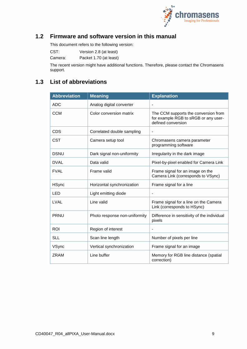
1.3 List of abbreviations
Abbreviation Meaning Explanation
ADC Analog digital converter -
CCM Color conversion matrix The CCM supports the conversion from for example RGB to sRGB or any user-defined conversion
CDS Correlated double sampling -
CST Camera setup tool Chromasens camera parameter programming software
DSNU Dark signal non-uniformity Irregularity in the dark image
DVAL Data valid Pixel-by-pixel enabled for Camera Link
FVAL Frame valid Frame signal for an image on the Camera Link (corresponds to VSync)
HSync Horizontal synchronization Frame signal for a line
LED Light emitting diode -
LVAL Line valid Frame signal for a line on the Camera Link (corresponds to HSync)
PRNU Photo response non-uniformity Difference in sensitivity of the individual pixels
ROI Region of interest -
SLL Scan line length Number of pixels per line
VSync Vertical synchronization Frame signal for an image
ZRAM Line buffer Memory for RGB line distance (spatial correction)
CD40047_R04_allPIXA_User-Manual.docx 10
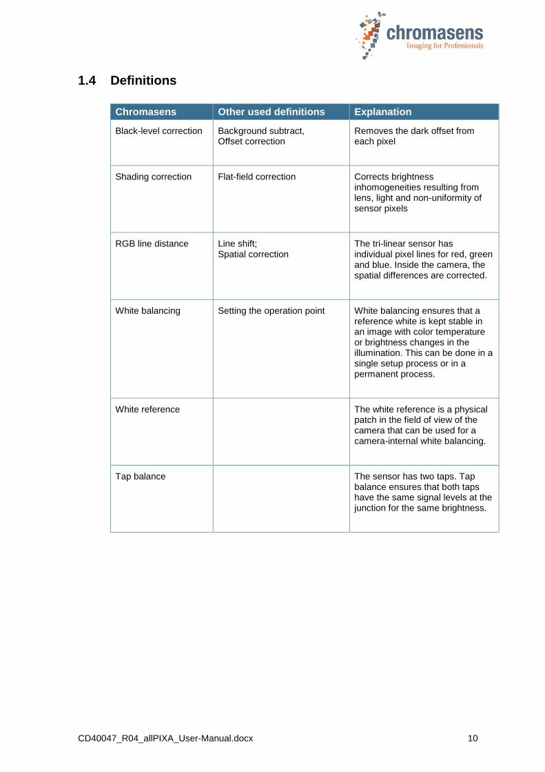
1.4 Definitions
Chromasens Other used definitions Explanation
Black-level correction Background subtract, Offset correction
Removes the dark offset from each pixel
Shading correction Flat-field correction
Corrects brightness inhomogeneities resulting from lens, light and non-uniformity of sensor pixels
RGB line distance Line shift; Spatial correction
The tri-linear sensor has individual pixel lines for red, green and blue. Inside the camera, the spatial differences are corrected.
White balancing Setting the operation point White balancing ensures that a reference white is kept stable in an image with color temperature or brightness changes in the illumination. This can be done in a single setup process or in a permanent process.
White reference The white reference is a physical patch in the field of view of the camera that can be used for a camera-internal white balancing.
Tap balance The sensor has two taps. Tap balance ensures that both taps have the same signal levels at the junction for the same brightness.
CD40047_R04_allPIXA_User-Manual.docx 11
1.5 Scope of supply of the allPIXA camera
Please check your device upon delivery to ensure that it is undamaged and complete.
The following components are supplied with the allPIXA camera:
allPIXA camera packaging
Check the packaging for damage which may have occurred during transport.
allPIXA camera
Check the camera for damage which may have occurred during transport.
The rating plate is located on the rear of the allPIXA camera. It shows the camera resolution and the serial number.
Additionally ordered and supplied accessories
Lens adapters, extension rings, lenses and other accessories are not included in the standard scope of delivery. These items must be ordered separately as accessories.
Check additionally ordered accessories for completeness and for damage which may have occurred during transport.
Read this manual carefully before using the camera, contacting your local partners or the Chromasens support.
Should there be any questions left, do not hesitate to contact your local partner or us.
We would be pleased to be of assistance to you.
1.6 Information about CST
CST = Camera Setup Tool
To download the newest version, refer to our website at http://www.chromasens.de.
To be able to log in, a registration is needed.
Before you install and use CST, please check whether there is a recent CST or manual version available. You can find the Software on the Chromasens homepage at Products Line Scan Camera allPIXA.
If you already have an installed version of the CST, you can check the version number using the Help menu.
For more information about CST, see chapter 9 “CST program window”.

CD40047_R04_allPIXA_User-Manual.docx 12
1.7 Design of a line scan camera system
The following figure demonstrates the basic setup of a typical line scan camera system
Figure 1: Design of a line scan camera application
The following components are necessary in a typical line scan camera application
Component No.
Line scan camera: An allPIXA camera which scans the image line-by-line and communicates with the frame grabber (5, PC plug-in card).
1
The optical system: Optical lenses with tubes and mounts with an adjusted focusing
2
Illumination: The illumination system lights up the information carrier/scan area on the passing object. The Chromasens Corona II illumination system is an ideal supplementary option for the allPIXA camera.
3
Illumination controller: Controls and monitors the illumination unit. The Chromasens Corona II illumination (3) has integrated temperature/voltage sensors which can be read out with the XLC4 controller. By using the XLC4 controller, the illumination unit can be monitored and kept stable.
4
Frame grabber (PC plug-in card): The image data are sent to a PC by means of a frame grabber with a CameraLink interface. The frame grabber establishes the necessary hardware connection to the PC (6).
5
PC: The PC system serves for subsequent processing of the image data and can optionally control the illumination system (3 + 4).
6
Speed detection: The speed of the object / conveyor belt can be detected by means of an optional incremental encoder. The encoder can be connected either to the allPIXA camera or to the frame grabber.
7
Conveying unit: The conveying unit moves the scanned object past the allPIXA camera
8
Power supply: Both, the allPIXA camera and the illumination system, require a suitable power supply.
9

CD40047_R04_allPIXA_User-Manual.docx 13
2 allPIXA camera - overview
The allPIXA camera family is available in the following maximum resolutions / line frequencies:
2,048 pixels / max. 60,6 kHz
4,096 pixels / max. 34,4 kHz
7,300 pixels / max. 21.2 kHz
If you are interested in further resolutions, do not hesitate to contact us.
The allPIXA camera provides all functions required for supplying images with the same color, brightness and resolution of each operational area.
The allPIXA camera is particularly suitable for inspection systems requiring a very high speed and a consistently high color quality.
Continuous white balancing is possible during image acquisition to ensure optimum color quality. In addition, offset and shading correction ensure the balance of different color pixel sensitivities (DSNU and PRNU) as well as the illumination process.
Via frame grabber, the incremental encoder can be either connected to the CC bits of the CameraLink interface or directly to the allPIXA camera. As a result, images with a consistent quality can be generated even at transport speeds with a high fluctuation rate.
The allPIXA camera parameters can be set with the CST software tool. Equipped with a CameraLink interface (medium), the allPIXA camera achieves a data rate of 170 megapixels per second with 24 bit RGB, which is equal to 510 Mbytes/s.
By using the allPIXA camera, you can also output monochrome / grayscale images.
The design was fully revised during development of the housing which is impressively tough but offers a number of screw mounting options. A wide range of adapter options makes the installation simple for users.
Modularity of the allPIXA camera permits the use of various lenses like C-mount, F-mount, M39x1/26“, M42x1, and M72x0.75 connections. In addition, the modular focus of LINOS / Qioptics is supported, and thus the allPIXA camera can be combined with all commercially available standard lenses.
2.1 allPIXA camera highlights
Trilinear color line scan camera (trilinear CCD line scan sensor)
10 µm pixel size
High-accuracy sensor alignment
24 bit (3x8 bit) color information on the output side
Maximum data rate of 170 MPx/s (24Bit RGB) – 510 MB/s
Internal 14-bit A/D conversion per color channel
RGB spatial compensation in the camera (also sub-pixel correction)
Shading correction, optionally calculated offline with CST or internally in the camera
Gamma correction, brightness and contrast controller, separate for each channel
Color conversion matrix (CCM)
Continuous white balancing maintains a constant image brightness and color, irrespective of the temperature and service life of the illumination system
Intelligent camera control by a 16-bit controller
FPGA-based image processing
Robust metal housing

CD40047_R04_allPIXA_User-Manual.docx 14
Connection of a wide range of lenses, possible for the use of special lens adapters
C-mount, F-mount, M39x1/26", M42x1, M72x0.75, modular focus (Qioptics / Germany)
Other mounts and customized solutions on request
Incremental encoder port on the camera; this ensures simple handling and less programming work
Internal test image generator
Option for area scanning with trigger inputs (light barriers)
2.2 Technical data
Sensor Trilinear CCD color line sensor
Pixel size 10 µm x 10 µm (10 µm pitch)
Line spacing 40 µm center distance R-G and G-B
Maximum data rate on the Camera Link
170 megapixels/s 24Bit RGB | 510 Mbytes/s
Resolution 1,024 (Only OEM) / 2,048 / 4,096 / 7,300 px Other sensor resolutions are available on request
Maximum line frequency
1,024 pixels: 110 kHz (only in special OEM configurations) 2,048 pixels: 60,7 kHz 4,096 pixels: 34,4 kHz 7,300 pixels: 21.2 kHz
Spectral sensitivity 360 nm to 960 nm
Video signal 3x8 bit on the CameraLink, 3x14 bit ADC
Interface CameraLink medium with 85 MHz
Line scan operating mode Free-running / external trigger (incremental encoder / line trigger)
Area scan operating mode Image size either free-running, fixed or based on trigger pulse width
Other interfaces
Power supply (6 pin Hirose, male)
External IO (15 pin D-Sub, female) Serial RS-232 (9 pin D-Sub, female)
Camera mount
C-mount, F-mount, M39x1/26“, M42x1,
M72x0.75, modular focus (LINOS / Qioptics), lens adapter and extension tubes
Certifications CE, FCC, RoHS
Power supply 24 VDC +/- 10 %; 1A; typical 16 W
Operating temperature 0°C to 60°C; 32°F to 140°F (housing temp.)
Housing dimensions L = 102 mm, H = 126 mm, D = 68 mm
Weight 1.2 kg
NOTE Depending on the power supply the power consumption might be up to 1 ampere at power up for a short time. It is recommended to provide a power supply with 24VDC/1amp or with higher possible power consumption.
CD40047_R04_allPIXA_User-Manual.docx 15
2.3 Mechanical dimensions of the allPIXA camera
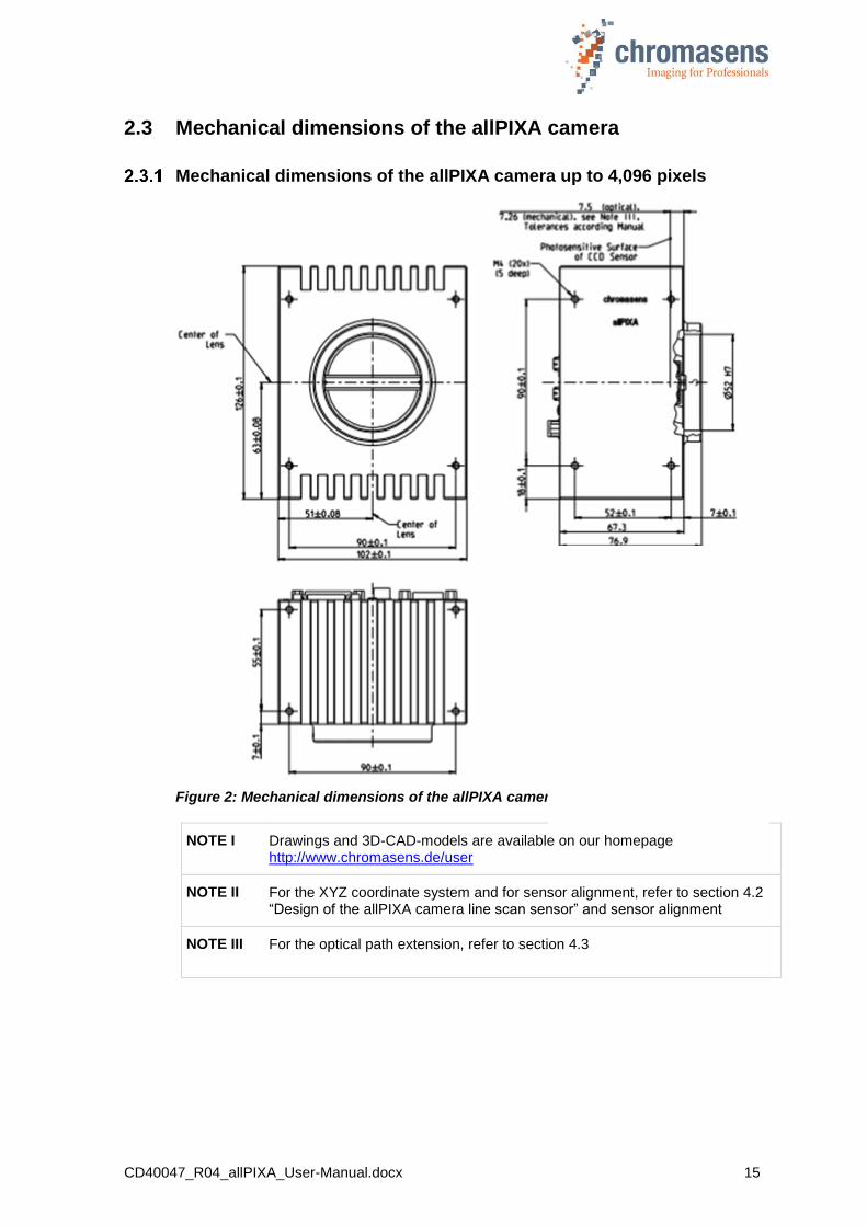
Mechanical dimensions of the allPIXA camera up to 4,096 pixels
Figure 2: Mechanical dimensions of the allPIXA camera with up to 4,096 pixels
NOTE I Drawings and 3D-CAD-models are available on our homepage http://www.chromasens.de/user
NOTE II For the XYZ coordinate system and for sensor alignment, refer to section 4.2 “Design of the allPIXA camera line scan sensor” and sensor alignment
NOTE III For the optical path extension, refer to section 4.3
CD40047_R04_allPIXA_User-Manual.docx 16
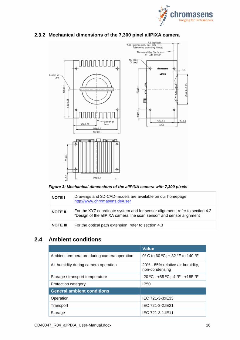
Mechanical dimensions of the 7,300 pixel allPIXA camera
Figure 3: Mechanical dimensions of the allPIXA camera with 7,300 pixels
NOTE I Drawings and 3D-CAD-models are available on our homepage http://www.chromasens.de/user
NOTE II For the XYZ coordinate system and for sensor alignment, refer to section 4.2 “Design of the allPIXA camera line scan sensor” and sensor alignment
NOTE III For the optical path extension, refer to section 4.3
2.4 Ambient conditions
Value
Ambient temperature during camera operation 0º C to 60 ºC; + 32 °F to 140 °F
Air humidity during camera operation 20% - 85% relative air humidity, non-condensing
Storage / transport temperature -20 ºC - +85 ºC; -4 °F - +185 °F
Protection category IP50
General ambient conditions
Operation IEC 721-3-3:IE33
Transport IEC 721-3-2:IE21
Storage IEC 721-3-1:IE11

CD40047_R04_allPIXA_User-Manual.docx 17
3 Safety
3.1 Depiction of safety instructions
Safety-relevant information is indicated in this manual as follows:
WARNING
Indicates a potentially hazardous situation or task, which, if not avoided, could result in serious injury or death.
CAUTION
Indicates a potentially hazardous situation or task, which, if not avoided, may result in minor or moderate injury.
Indicates a potentially hazardous situation or task, which, if not avoided, could result in damage to the product or the surrounding environment.
3.2 Basic safety regulations
The basic safety regulations always observe the following:
Do not attempt to install the device or start operation before you have read all supplied documentation carefully and have understood its contents.
Safe and correct operation of the device requires correct and appropriate transport, storage, mounting, and installation as well as careful operation and maintenance.
Operation of the allPIXA camera device is only permitted when it is in a faultless and safe condition. In the event of any fault or defect, the allPIXA camera, the machine or the system in which the allPIXA camera is installed, must be stopped immediately and the responsible person has to be informed.
Modifications and extensions to the allPIXA camera are only permitted if the prior written consent of Chromasens GmbH is obtained. This applies in particular to modifications and extensions which can negatively affect the safety of the allPIXA camera.
Compliance with the ambient conditions described in this manual is essential.
CD40047_R04_allPIXA_User-Manual.docx 18
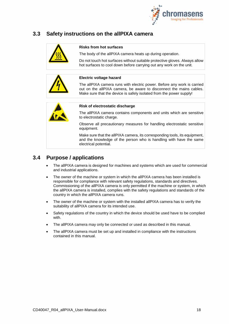
3.3 Safety instructions on the allPIXA camera
Risks from hot surfaces
The body of the allPIXA camera heats up during operation.
Do not touch hot surfaces without suitable protective gloves. Always allow hot surfaces to cool down before carrying out any work on the unit.
Electric voltage hazard
The allPIXA camera runs with electric power. Before any work is carried out on the allPIXA camera, be aware to disconnect the mains cables. Make sure that the device is safely isolated from the power supply!
Risk of electrostatic discharge
The allPIXA camera contains components and units which are sensitive to electrostatic charge.
Observe all precautionary measures for handling electrostatic sensitive equipment.
Make sure that the allPIXA camera, its corresponding tools, its equipment, and the knowledge of the person who is handling with have the same electrical potential.
3.4 Purpose / applications
The allPIXA camera is designed for machines and systems which are used for commercial and industrial applications.
The owner of the machine or system in which the allPIXA camera has been installed is responsible for compliance with relevant safety regulations, standards and directives. Commissioning of the allPIXA camera is only permitted if the machine or system, in which the allPIXA camera is installed, complies with the safety regulations and standards of the country in which the allPIXA camera runs.
The owner of the machine or system with the installed allPIXA camera has to verify the suitability of allPIXA camera for its intended use.
Safety regulations of the country in which the device should be used have to be complied with.
The allPIXA camera may only be connected or used as described in this manual.
The allPIXA camera must be set up and installed in compliance with the instructions contained in this manual.

CD40047_R04_allPIXA_User-Manual.docx 19
3.5 Staff requirements
The system owner must ensure that all persons working on the system are trained for the required work and have read and understood this manual. This applies particularly to the employees who only work occasionally with the allPIXA camera, for example, during commissioning and maintenance work.
Work on the electrical installation of the system may only be carried out by a qualified electrician or person who has undergone the necessary electrotechnical training under the supervision of a qualified electrician, in compliance with applicable electrotechnical regulations.
Please be aware that only suitably trained and qualified persons are permitted to work with the allPIXA camera. Such persons are qualified to work with the allPIXA camera device, if they are familiar with its assembly, installation, care, and all necessary precautionary measures.
Assignments and responsibilities of the staff charged with operation, commissioning, maintenance and repair have to be clearly defined and specified by the owner of the device in which the allPIXA camera is installed.
3.6 Organisational measurements
The instruction manual has to be stored safely in the vicinity of the camera in operation.
Information contained in this manual have to be integrated into the documentation of the device in which the allPIXA camera is installed.
The allPIXA camera and all connected peripheries have to be checked regularly for visible external damages.
3.7 Safety instructions for maintenance / cleaning
Before carrying out any service or maintenance work, the responsible staff has to be informed.
Deadlines and intervals for regular inspections must be complied with.
Before starting maintenance, the allPIXA camera must be isolated from the power supply.
Due to the risk of fire, devices such as radiators, heaters, or lighting equipment have to be allowed first to cool down.
Only technicians of the Chromasens GmbH are permitted to open or slacken screws or housing sections of the allPIXA camera!
Necessary repairs may only be carried out by the Chromasens GmbH.
Cleaning of the device is only allowed with a soft, lint-free cloth and Isopropanol (optional).
To avoid damages, the camera may only be transported in its original packaging.
CD40047_R04_allPIXA_User-Manual.docx 20
4 allPIXA camera - Design and functions
4.1 Basic design of the allPIXA camera
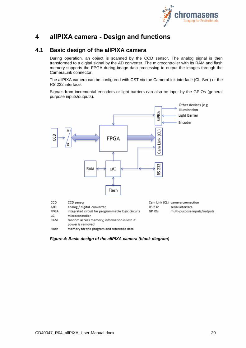
During operation, an object is scanned by the CCD sensor. The analog signal is then transformed to a digital signal by the AD converter. The microcontroller with its RAM and flash memory supports the FPGA during image data processing to output the images through the CameraLink connector.
The allPIXA camera can be configured with CST via the CameraLink interface (CL-Ser.) or the RS 232 interface.
Signals from incremental encoders or light barriers can also be input by the GPIOs (general purpose inputs/outputs).
Figure 4: Basic design of the allPIXA camera (block diagram)
CD40047_R04_allPIXA_User-Manual.docx 21
4.2 Design of the allPIXA camera line scan sensor
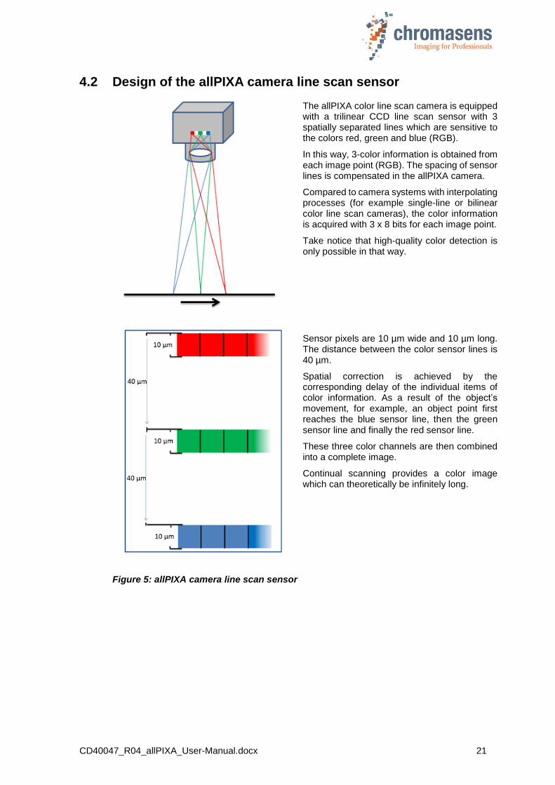
The allPIXA color line scan camera is equipped with a trilinear CCD line scan sensor with 3 spatially separated lines which are sensitive to the colors red, green and blue (RGB).
In this way, 3-color information is obtained from each image point (RGB). The spacing of sensor lines is compensated in the allPIXA camera.
Compared to camera systems with interpolating processes (for example single-line or bilinear color line scan cameras), the color information is acquired with 3 x 8 bits for each image point.
Take notice that high-quality color detection is only possible in that way.
Sensor pixels are 10 µm wide and 10 µm long. The distance between the color sensor lines is 40 µm.
Spatial correction is achieved by the corresponding delay of the individual items of color information. As a result of the object’s movement, for example, an object point first reaches the blue sensor line, then the green sensor line and finally the red sensor line.
These three color channels are then combined into a complete image.
Continual scanning provides a color image which can theoretically be infinitely long.
Figure 5: allPIXA camera line scan sensor

CD40047_R04_allPIXA_User-Manual.docx 22
4.3 Sensor allignment and orientation
Sensor alignment:
Position: X: < +/- 150 µm Y: < +/- 150 µm Z: < +/- 150 µm
Rotation about: Y: < +/- 0.1 ° Z: < +/- 0.1 °
Planarity of sensor surface: < +/- 0.50 µm
Sensor window:
Thickness: 0.7 mm Refraction index 1.5 Optical path extension: 0.24 mm
Sensor orientation: (view from the front side)
First pixel: Left side
Color lines: Blue: top Green: center Red: bottom
Sensor alignment is an important issue for:
Adjusting multi camera systems
Replacing cameras
Mechanical design of the mounting system for the camera
X
Y
Z
First pixel

CD40047_R04_allPIXA_User-Manual.docx 23
4.4 The allPIXA camera line scan sensor readout principle
The odd and even pixels of each line are moved to the respective readout register. Therefore, the allPIXA camera simultaneously processes 3x2x2 channels - 3 colors, 2 taps and both (odd and even pixels).
Figure 6: The allPIXA camera line scan sensor readout principle
4.5 Spectral sensitivity of the allPIXA camera line scan sensor
Figure 7: Spectral sensitivity of the line scan sensor
Wave length (nm)
CD40047_R04_allPIXA_User-Manual.docx 24
4.6 Image processing
Image processing in the allPIXA camera is analog and digital. The following block diagram illustrates the internal processes.
Analog / digital image processing
The power block provides all required voltages which are available for the camera electronic components from the supplied 24 V DC.
The image is acquired by the CCD sensor and initially processed in analog mode, followed by an analog/digital converter. The digital image processing is done in the FPGA.
The image data generated by the allPIXA camera are converted in the video interface to the Camera Link standard and then sent to the frame grabber.
Figure 8: Process of the allPIXA camera image processing (block diagram)
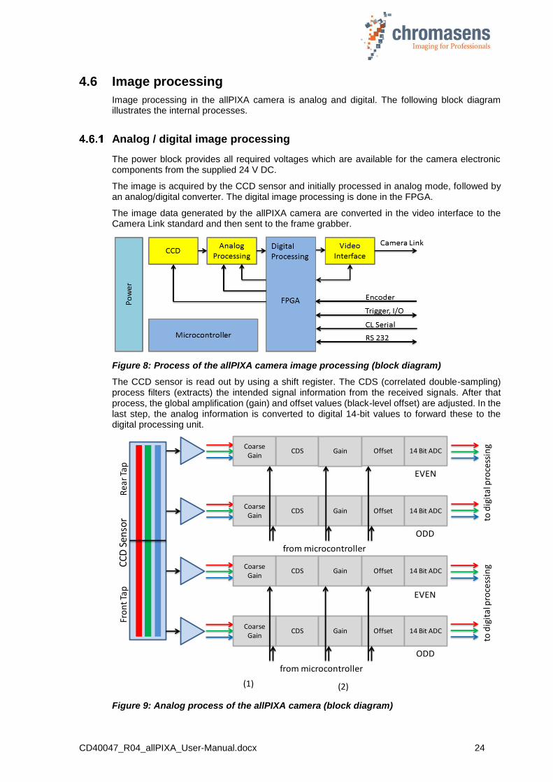
The CCD sensor is read out by using a shift register. The CDS (correlated double-sampling) process filters (extracts) the intended signal information from the received signals. After that process, the global amplification (gain) and offset values (black-level offset) are adjusted. In the last step, the analog information is converted to digital 14-bit values to forward these to the digital processing unit.
Figure 9: Analog process of the allPIXA camera (block diagram)
CDS Gain Offset 14 Bit ADC
CDS Gain Offset 14 Bit ADC
from microcontroller
tod
igit
al p
roce
ssin
gEVEN
ODD
CDS Gain Offset 14 Bit ADC
CDS Gain Offset 14 Bit ADC
from microcontroller
tod
igit
al p
roce
ssin
g
ODD
Fro
nt T
apR
earT
apC
CD
Sen
sor
EVEN
CoarseGain
CoarseGain
CoarseGain
CoarseGain
(1) (2)

CD40047_R04_allPIXA_User-Manual.docx 25
The signals are transferred from the analog-digital converter and run through a multiplexer that switches between the test image generator and the input signals as shown in Figure 10.
Figure 10: Digital process of the allPIXA camera (block diagram)
First, the pixel-by-pixel black-level correction (1) and shading correction (2) is carried out, then the image data are adjusted with the values programmed for brightness and contrast (3). Afterwards, the spatial correction (RGB) is carried out in the line buffer (ZRAM) (4) and the colors are adjusted with the color conversion matrix (5) and the gamma correction (6). The color image can also be converted into a gray image by the FPGA (7). Auxiliary data can be added to each line before the image data are output via the CameraLink connection (8).

CD40047_R04_allPIXA_User-Manual.docx 26
Image information output on the CameraLink
The sensor is read out in two sections (in front tap and rear tap). The front part is output via CameraLink connector 1 (CL-Con 1), and the rear part is output via CameraLink connector 2 (CL-Con 2).
Figure 11: Image information output on the CameraLink
With Regard to the CameraLink draft description for sensors, the read-out system is called “2XE”.
Figure 12
NOTE Take notice that some frame grabbers use this term and others use terms for “read in”, therefore, the direction might be inversed.

CD40047_R04_allPIXA_User-Manual.docx 27
In color mode, the CameraLink uses 2XE format with 3x8 bits per pixel transmitted on both CameraLink connectors. If set to gray, 2 pixels with 8 bits are transmitted on the first CameraLink connector.
According to the CameraLink specification, the data are transmitted as displayed in the following table:
Connector 0 (CL1) Connector1 (CL2) Conn0/Conn1
Output format “Color”
24Bit RGB
Output format “Grey”
8Bit*2 Grey
Input Name Output format “Color”
24Bit RGB
Input Name Trans/Rec Number
PxCLK PxCLK Strobe PxCLK Strobe TxClk/RxClkt
LVAL LVAL LVAL LVAL LVAL TX24/RX24
FVAL FVAL FVAL FVAL FVAL TX25/RX25
Pen Pen DVAL Pen DVAL TX26/RX26
Spare Spare Spare Spare Spare TX23/RX23
Red Front Bit 0 Front Bit 0 Port A0 Red Rear Bit 0 Port D0 TX0/RX0
Red Front Bit 1 Front Bit 1 Port A1 Red Rear Bit 1 Port D1 TX1/RX1
Red Front Bit 2 Front Bit 2 Port A2 Red Rear Bit 2 Port D2 TX2/RX2
Red Front Bit 3 Front Bit 3 Port A3 Red Rear Bit 3 Port D3 TX3/RX3
Red Front Bit 4 Front Bit 4 Port A4 Red Rear Bit 4 Port D4 TX4/RX4
Red Front Bit 5 Front Bit 5 Port A5 Red Rear Bit 5 Port D5 TX6/RX6
Red Front Bit 6 Front Bit 6 Port A6 Red Rear Bit 6 Port D6 TX27/RX27
Red Front Bit 7 Front Bit 7 Port A7 Red Rear Bit 7 Port D7 TX5/RX5
Green Front Bit 0 Rear Bit 0 Port B0 Green Rear Bit 0 Port E0 TX7/RX7
Green Front Bit 1 Rear Bit 1 Port B1 Green Rear Bit 1 Port E1 TX8/RX8
Green Front Bit 2 Rear Bit 2 Port B2 Green Rear Bit 2 Port E2 TX9/RX9
Green Front Bit 3 Rear Bit 3 Port B3 Green Rear Bit 3 Port E3 TX12/RX12
Green Front Bit 4 Rear Bit 4 Port B4 Green Rear Bit 4 Port E4 TX13/RX13
Green Front Bit 5 Rear Bit 5 Port B5 Green Rear Bit 5 Port E5 TX14/RX14
Green Front Bit 6 Rear Bit 6 Port B6 Green Rear Bit 6 Port E6 TX10/RX10
Green Front Bit 7 Port B7 Green Rear Bit 7 Port E7 TX11/RX11
Blue Front Bit 0 Port C0 Blue Rear Bit 0 Port F0 TX15/RX15
Blue Front Bit 1 Port C1 Blue Rear Bit 1 Port F1 TX18/RX18
Blue Front Bit 2 Port C2 Blue Rear Bit 2 Port F2 TX19/RX19
Blue Front Bit 3 Port C3 Blue Rear Bit 3 Port F3 TX20/RX20
Blue Front Bit 4 Port C4 Blue Rear Bit 4 Port F4 TX21/RX21
Blue Front Bit 5 Port C5 Blue Rear Bit 5 Port F5 TX22/RX22
Blue Front Bit 6 Port C6 Blue Rear Bit 6 Port F6 TX16/RX16
Blue Front Bit 7 Port C7 Blue Rear Bit 7 Port F7 TX17/RX17
Figure 13: Tranmission of data according CameraLink specification CameraLink

CD40047_R04_allPIXA_User-Manual.docx 28
4.7 Black-level correction and shading (flat-field) correction
The allPIXA camera supports black-level (offset) and shading correction.
The following points are important for understanding these kinds of operation:
Both operations are based on pixel-by-pixel calculation, and the effects on behavior of single pixels such as PRNU (photo response non uniformity) are eliminated.
Both operations are carried out separately for each line (red, green, blue).
The allPIXA camera provides four data sets for black-level correction and four data sets for shading correction Therefore, you could deal with for example four different lighting systems by selecting the necessary data sets without transferring or generating new shading data.
Calculation of the correction data sets can be done offline on scanned images. Often, shading data have been calculated internally with a static white reference in front of the camera. In this case, spots of dust on the white reference lead to vertical lines in the image. This effect can be eliminated by slightly defocusing the lens during the generation of the references. The lighting distribution is then seen by the sensor and the lens. Another possibility to avoid this problem is to move the target slightly during the balancing process. Thus, distortions for example caused by dust can be eliminated.
The allPIXA camera permits to calculate the references offline. You can select a scanned image and define a region of the image, in which shading correction data are calculated. By averaging over a higher number of lines, distortions, for example caused by dust on the target, are eliminated. Therefore, it is possible to use an image with a moving white object.
The allPIXA camera also permits to generate shading and offset data internally.
Generated data sets can be stored on the hard disk of the PC. The stored data can be transferred to the camera later on.
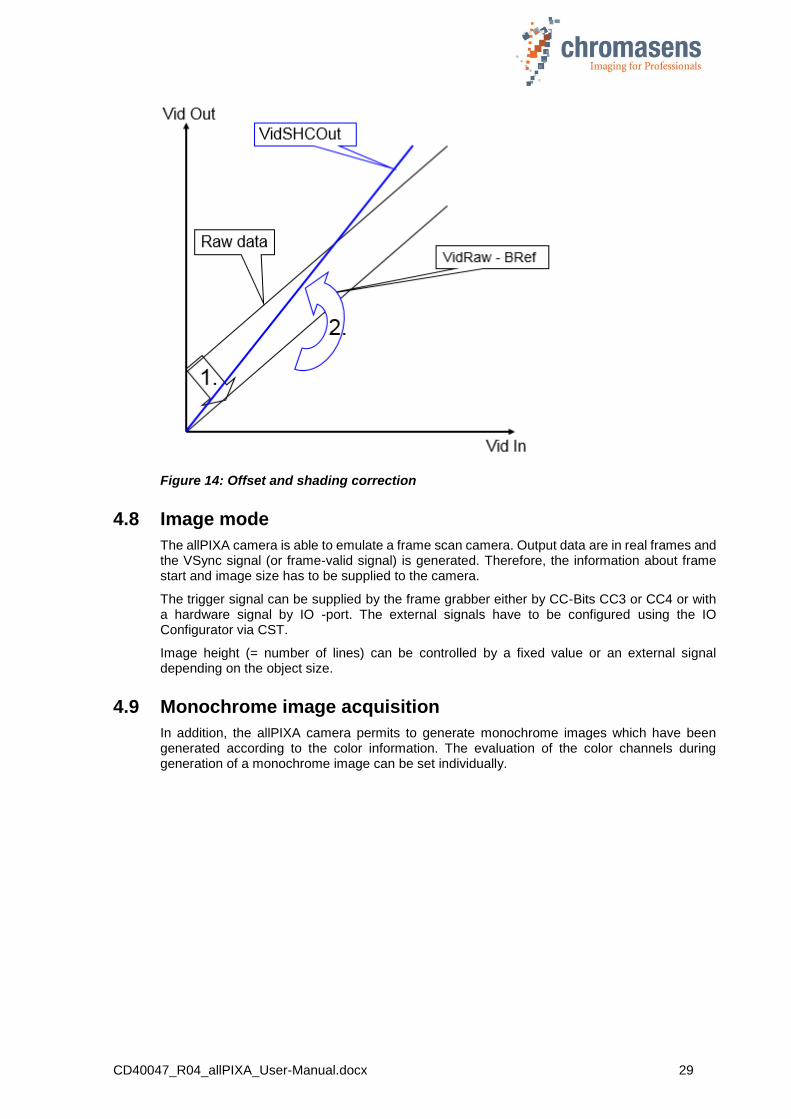
For the calculation the following formulas can be used:
Mode Recording of black reference line:
BRef(x) = VidRaw with black template or without illumination
Mode Recording of white reference line:
WRef(x) = VidRaw(x) – BRef(x) with white template
Mode / Correction (white and black correction is activated)
VidSHCOut(x,y) = (VidRaw(x,y) – BRef(x)) * VidMax
WRef(x)
This calculation is done separately for all color separations (RGB).
BRef Black Reference value for each pixel in the line
WRef White Reference value for each pixel in the line
VidRaw Raw values for each pixel output by A/D-Converter
(x, y) Number of pixels within the line or column
VidMax Maximum brightness value
VidSHCOut(x,y) Offset- and Shading-corrected pixels of the image
CD40047_R04_allPIXA_User-Manual.docx 29
Figure 14: Offset and shading correction
4.8 Image mode
The allPIXA camera is able to emulate a frame scan camera. Output data are in real frames and the VSync signal (or frame-valid signal) is generated. Therefore, the information about frame start and image size has to be supplied to the camera.
The trigger signal can be supplied by the frame grabber either by CC-Bits CC3 or CC4 or with a hardware signal by IO -port. The external signals have to be configured using the IO Configurator via CST.
Image height (= number of lines) can be controlled by a fixed value or an external signal depending on the object size.
4.9 Monochrome image acquisition
In addition, the allPIXA camera permits to generate monochrome images which have been generated according to the color information. The evaluation of the color channels during generation of a monochrome image can be set individually.

CD40047_R04_allPIXA_User-Manual.docx 30
4.10 White balancing with a closed-loop control
To keep the video values stable on a white reference target, the allPIXA camera supports an automatic adjustment of the internal gain values. Therefore, a closed loop can be established which enables an automatism of keeping the white-point stable, even if there are brightness or color temperature changes in the illumination. Usually, automatic camera functions use the brightest point for adjusting the best result to get the white color.
The allPIXA camera permits to arbitrarily define the area of an image chosen as reference and you are also able to set the reference values (target values) separately for each channel.
Figure 15: Closed loop control for white balancing
This function can be used for:
A single setup process with a static white reference in front of the camera during its installation.
Adjusting the camera continuously during the scanning process. Therefore, it is possible to compensate the warming up or the aging of the light source.
CD40047_R04_allPIXA_User-Manual.docx 31
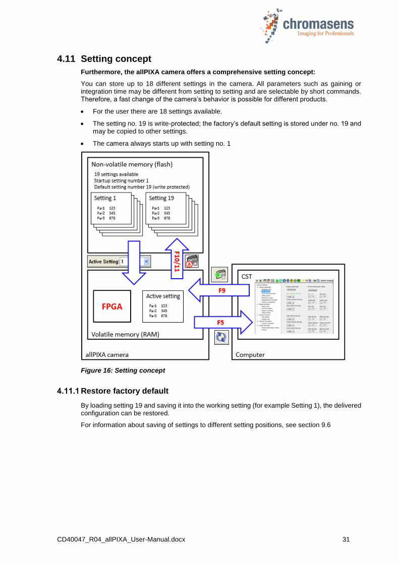
4.11 Setting concept
Furthermore, the allPIXA camera offers a comprehensive setting concept:
You can store up to 18 different settings in the camera. All parameters such as gaining or integration time may be different from setting to setting and are selectable by short commands. Therefore, a fast change of the camera’s behavior is possible for different products.
For the user there are 18 settings available.
The setting no. 19 is write-protected; the factory’s default setting is stored under no. 19 and may be copied to other settings.
The camera always starts up with setting no. 1
Figure 16: Setting concept
Restore factory default
By loading setting 19 and saving it into the working setting (for example Setting 1), the delivered configuration can be restored.
For information about saving of settings to different setting positions, see section 9.6
CD40047_R04_allPIXA_User-Manual.docx 32
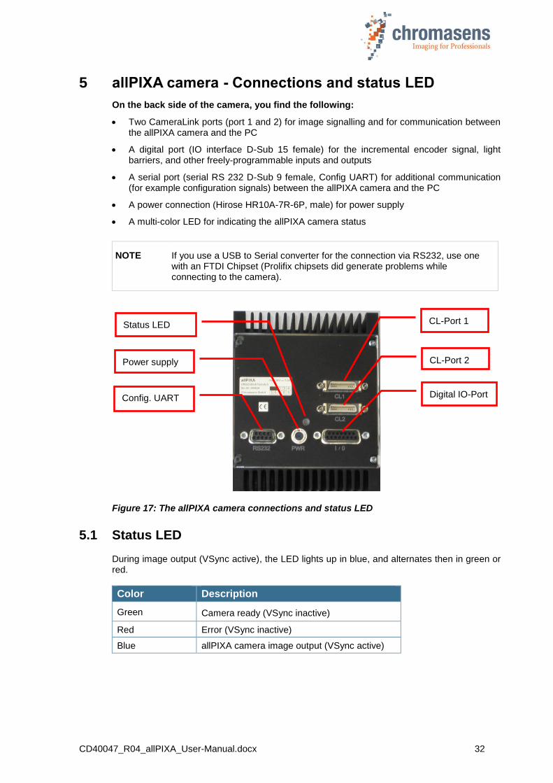
5 allPIXA camera - Connections and status LED
On the back side of the camera, you find the following:
Two CameraLink ports (port 1 and 2) for image signalling and for communication between the allPIXA camera and the PC
A digital port (IO interface D-Sub 15 female) for the incremental encoder signal, light barriers, and other freely-programmable inputs and outputs
A serial port (serial RS 232 D-Sub 9 female, Config UART) for additional communication (for example configuration signals) between the allPIXA camera and the PC
A power connection (Hirose HR10A-7R-6P, male) for power supply
A multi-color LED for indicating the allPIXA camera status
NOTE If you use a USB to Serial converter for the connection via RS232, use one with an FTDI Chipset (Prolifix chipsets did generate problems while connecting to the camera).
Figure 17: The allPIXA camera connections and status LED
5.1 Status LED
During image output (VSync active), the LED lights up in blue, and alternates then in green or red.
Color Description
Green Camera ready (VSync inactive)
Red Error (VSync inactive)
Blue allPIXA camera image output (VSync active)
CL-Port 1
CL-Port 2
Digital IO-Port
Status LED
Power supply
Config. UART

CD40047_R04_allPIXA_User-Manual.docx 33
5.2 Power supply
Take notice that the following connector is required for the power supply cable:
Manufacturer: Hirose Article no.: HR10A-7P-6S “female” (male connector is located on the camera)
Pin no. Description
1 Power +24 V
2 Power +24 V
3 Not connected
4 Not connected
5 Ground
6 Ground
For more information about the input voltage and currents, see section 2.2 “Technical data”.
5.3 Config UART (serial RS 232)
Serial connection to the PC can be established by using a 9-pin D-Sub connector (male) via the interface of serial RS 232 (V24).
Pin no. Description
1 Not connected
2 Transmit data
3 Receive data
4 Data terminal ready
5 Ground
6 Not connected
7 Request to send
8 Not connected
9 Not connected
Pin 1
CD40047_R04_allPIXA_User-Manual.docx 34
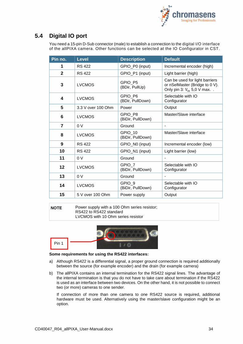
5.4 Digital IO port
You need a 15-pin D-Sub connector (male) to establish a connection to the digital I/O interface of the allPIXA camera. Other functions can be selected at the IO Configurator in CST.
Pin no. Level Description Default
1 RS 422 GPIO_P0 (input) Incremental encoder (high)
2 RS 422 GPIO_P1 (input) Light barrier (high)
3 LVCMOS GPIO_P5 (BDir, PullUp)
Can be used for light barriers or nSelMaster (Bridge to 0 V). Only pin 3: Vin 5,0 V max. .
4 LVCMOS GPIO_P6 (BDir, PullDown)
Selectable with IO Configurator
5 3.3 V over 100 Ohm Power Output
6 LVCMOS GPIO_P8 (BiDir, PullDown)
Master/Slave interface
7 0 V Ground -
8 LVCMOS GPIO_10 (BiDir, PullDown)
Master/Slave interface
9 RS 422 GPIO_N0 (input) Incremental encoder (low)
10 RS 422 GPIO_N1 (input) Light barrier (low)
11 0 V Ground -
12 LVCMOS GPIO_7 (BiDir, PullDown)
Selectable with IO Configurator
13 0 V Ground -
14 LVCMOS GPIO_9 (BiDir, PullDown)
Selectable with IO Configurator
15 5 V over 100 Ohm Power supply Output
NOTE Power supply with a 100 Ohm series resistor; RS422 to RS422 standard LVCMOS with 10 Ohm series resistor
Some requirements for using the RS422 interfaces:
a) Although RS422 is a differential signal, a proper ground connection is required additionally between the source (for example encoder) and the drain (for example camera)
b) The allPIXA contains an internal termination for the RS422 signal lines. The advantage of the internal termination is that you do not have to take care about termination if the RS422 is used as an interface between two devices. On the other hand, it is not possible to connect two (or more) cameras to one sender.
If connection of more than one camera to one RS422 source is required, additional hardware must be used. Alternatively using the master/slave configuration might be an option.
Pin 1

CD40047_R04_allPIXA_User-Manual.docx 35
LVCMOS and RS422 levels
I/O standard Vmin Vmax Vmin Vmax Vmax Vmin
LVCMOS -0.5 0.7 1.7 3.6 0.4 2.1
RS422 -6 0,8 2 6
Maximum input level of the LVCMOS is 3.6 V!
Use a level converter, if necessary (for example 74 LVC14).
Non-compliance can result in irreparable damages to the allPIXA camera!
5.5 Video CameraLink port 1
CameraLink cables are supplied ready-for-use in different lengths varying from 1 m to 10 m. For connection to the allPIXA camera you need a 26-pin MDR mini-D ribbon (male) connector.
Cable designation
Camera connector: CL 1
Frame grabber connector
Channel link signal: Base
Inner shield 1 1 Inner shield
Inner shield 14 14 Inner shield
PAIR1- 2 25 X0-
PAIR1+ 15 12 X0+
PAIR2- 3 24 X1-
PAIR2+ 16 11 X1+
PAIR3- 4 23 X2-
PAIR3+ 17 10 X2+
PAIR4- 5 22 Xclk-
PAIR4+ 18 9 Xclk+
PAIR5- 6 21 X3-
PAIR5+ 19 8 X3+
PAIR6+ 7 20 SerTC+
PAIR6- 20 7 SerTC-
PAIR7- 8 19 SerTFG-
PAIR7+ 21 6 SerTFG+
PAIR8- 9 18 CC1-
PAIR8+ 22 5 CC1+
PAIR9+ 10 17 CC2+
PAIR9- 23 4 CC2-
PAIR10- 11 16 CC3-
PAIR10+ 24 3 CC3+
PAIR11+ 12 15 CC4+
PAIR11- 25 2 CC4-
Inner shield 13 13 Inner shield
Inner shield 26 26 Inner shield
Take notice that for high cable lengths (more than 6 m) high-quality cables are recommended. Alternatively, the CameraLink transmission speed can be reduced using CST configuration. The setup of frame grabber, cable and camera must be tested in advance to guarantee the required functionality.
CD40047_R04_allPIXA_User-Manual.docx 36
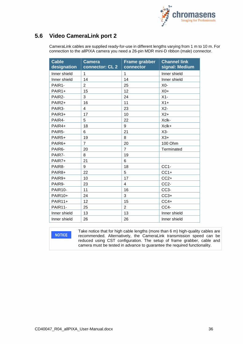
5.6 Video CameraLink port 2
CameraLink cables are supplied ready-for-use in different lengths varying from 1 m to 10 m. For connection to the allPIXA camera you need a 26-pin MDR mini-D ribbon (male) connector.
Cable designation
Camera connector: CL 2
Frame grabber connector
Channel link signal: Medium
Inner shield 1 1 Inner shield
Inner shield 14 14 Inner shield
PAIR1- 2 25 X0-
PAIR1+ 15 12 X0+
PAIR2- 3 24 X1-
PAIR2+ 16 11 X1+
PAIR3- 4 23 X2-
PAIR3+ 17 10 X2+
PAIR4- 5 22 Xclk-
PAIR4+ 18 9 Xclk+
PAIR5- 6 21 X3-
PAIR5+ 19 8 X3+
PAIR6+ 7 20 100 Ohm
PAIR6- 20 7 Terminated
PAIR7- 8 19
PAIR7+ 21 6
PAIR8- 9 18 CC1-
PAIR8+ 22 5 CC1+
PAIR9+ 10 17 CC2+
PAIR9- 23 4 CC2-
PAIR10- 11 16 CC3-
PAIR10+ 24 3 CC3+
PAIR11+ 12 15 CC4+
PAIR11- 25 2 CC4-
Inner shield 13 13 Inner shield
Inner shield 26 26 Inner shield
Take notice that for high cable lengths (more than 6 m) high-quality cables are recommended. Alternatively, the CameraLink transmission speed can be reduced using CST configuration. The setup of frame grabber, cable and camera must be tested in advance to guarantee the required functionality.

CD40047_R04_allPIXA_User-Manual.docx 37
5.7 Optical accessories
Lenses and mounts
Chromasens offers a large variety of accessories which are designed to provide maximum flexibility and get most out of the camera.
You can find the complete list of all accessories including descriptions and detailed drawings on our Website https://www.chromasens.de/en
In the following figure you can see a conventional range of adapters and lenses for the allPIXA camera devices up to 7,300 pixels (left) and 4,096 pixels (right):
Figure 18: Selection of optical accessories
CD40047_R04_allPIXA_User-Manual.docx 38
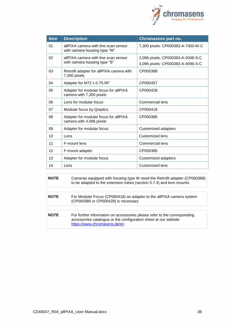
Item Description Chromasens part no.
01 allPIXA camera with line scan sensor with camera housing type “W”
7,300 pixels: CP000383-A-7300-W-C
02 allPIXA camera with line scan sensor with camera housing type “S”
2,096 pixels: CP000383-A-2048-S-C
4,096 pixels: CP000383-A-4096-S-C
03 Retrofit adapter for allPIXA camera with 7,300 pixels
CP000388
04 Adapter for M72 x 0.75-RF CP000457
05 Adapter for modular focus for allPIXA camera with 7,300 pixels
CP000428
06 Lens for modular focus Commercial lens
07 Modular focus by Qioptics CP000418
08 Adapter for modular focus for allPIXA camera with 4,096 pixels
CP000386
09 Adapter for modular focus Customized adapters
10 Lens Customized lens
11 F-mount lens Commercial lens
12 F-mount adapter CP000385
13 Adapter for modular focus Customized adapters
14 Lens Customized lens
NOTE Cameras equipped with housing type W need the Retrofit adapter (CP000388) to be adapted to the extension tubes (section 5.7.4) and lens mounts.
NOTE For Modular Focus (CP000418) an adapter to the allPIXA camera system (CP000386 or CP000428) is necessary
NOTE For further information on accessories please refer to the corresponding accessories catalogue or the configuration sheet at our website https://www.chromasens.de/en
CD40047_R04_allPIXA_User-Manual.docx 39
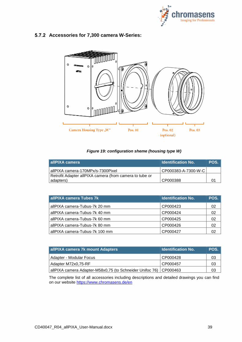
Accessories for 7,300 camera W-Series:
Figure 19: configuration sheme (housing type W)
allPIXA camera Identification No. POS.
allPIXA camera-170MPx/s-7300Pixel CP000383-A-7300-W-C
Retrofit Adapter allPIXA camera (from camera to tube or adapters) CP000388 01
allPIXA camera Tubes 7k Identification No. POS.
allPIXA camera-Tubus-7k 20 mm CP000423 02
allPIXA camera-Tubus-7k 40 mm CP000424 02
allPIXA camera-Tubus-7k 60 mm CP000425 02
allPIXA camera-Tubus-7k 80 mm CP000426 02
allPIXA camera-Tubus-7k 100 mm CP000427 02
allPIXA camera 7k mount Adapters Identification No. POS.
Adapter - Modular Focus CP000428 03
Adapter M72x0,75-RF CP000457 03
allPIXA camera Adapter-M58x0,75 (to Schneider Unifoc 76) CP000463 03
The complete list of all accessories including descriptions and detailed drawings you can find on our website https://www.chromasens.de/en
CD40047_R04_allPIXA_User-Manual.docx 40
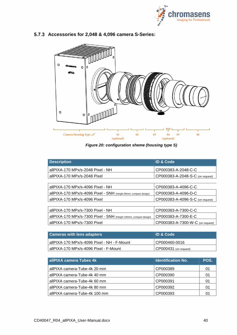
Accessories for 2,048 & 4,096 camera S-Series:
Figure 20: configuration sheme (housing type S)
Description ID & Code
allPIXA-170 MPx/s-2048 Pixel - NH CP000383-A-2048-C-C
allPIXA-170 MPx/s-2048 Pixel CP000383-A-2048-S-C (on request)
allPIXA-170 MPx/s-4096 Pixel - NH CP000383-A-4096-C-C
allPIXA-170 MPx/s-4096 Pixel - SNH (Height 95mm, compact design) CP000383-A-4096-D-C
allPIXA-170 MPx/s-4096 Pixel CP000383-A-4096-S-C (on request)
allPIXA-170 MPx/s-7300 Pixel - NH CP000383-A-7300-C-C
allPIXA-170 MPx/s-7300 Pixel - SNH (Height 100mm, compact design) CP000383-A-7300-E-C
allPIXA-170 MPx/s-7300 Pixel CP000383-A-7300-W-C (on request)
Cameras with lens adapters ID & Code
allPIXA-170 MPx/s-4096 Pixel - NH - F-Mount CP000460-0016
allPIXA-170 MPx/s-4096 Pixel - F-Mount CP000431 (on request)
allPIXA camera Tubes 4k Identification No. POS.
allPIXA camera-Tube-4k 20 mm CP000389 01
allPIXA camera-Tube-4k 40 mm CP000390 01
allPIXA camera-Tube-4k 60 mm CP000391 01
allPIXA camera-Tube-4k 80 mm CP000392 01
allPIXA camera-Tube-4k 100 mm CP000393 01

CD40047_R04_allPIXA_User-Manual.docx 41
allPIXA camera 4k direct mount Adapters Identification No. POS.
allPIXA camera F-Mount Adapter CP000385 02
allPIXA camera C-Mount-Adapter CP000387 02
allPIXA camera 4K-Adapter M42x1-A45,46 CP000434 02
allPIXA camera Adapter-MF ( to Modular Focus ) CP000386 02
allPIXA camera Adapter-M42x0,75 (to Schneider Unifoc 58 (T2)) CP000461 02
allPIXA camera Adapter-V-Mount (to Schneider Unifoc 12 (V-Mount)) CP000462 02
allPIXA camera 4k additional parts Identification No. POS.
Additional parts (custom specific) only on request 03 - 06
The complete list of all accessories including descriptions and detailed drawings you can find on our website https://www.chromasens.de/en
Mounting of the extension tube systems
The extension tubes are used for extending the image distance between the allPIXA camera (lens reference area) and the lens adapter, and the optical image can be varied with this system. Individual extension tubes are available in 20 mm stages and can be interconnected.
Figure 21: allPIXA camera 7300 (W-housing and Retrofit adapter) with extension tubes
If it is necessary to adjust the image distance with the aid of extension tubes, they have to be combined and connected with grub screws (Allen key size 1.5 mm, maximum torque 30 Ncm).
Additionally, it is necessary to secure the lens and the lens adapter plate with grub screws to the extension tubes.
Figure 22: Securing the extension tubes with grub screws
Figure 23: Mounting the lens adapter plate

CD40047_R04_allPIXA_User-Manual.docx 42
Mounting of a lens adapter ring
Lens adapter ring is mounted on the retrofit adapter (Figure 24).
Figure 24: Mounting the lens adapter ring on the retrofit adapter
The lens adapter ring is secured by grub screws (Allen key size 1.5 mm, max. torque 30 Ncm) to the retrofit adapter.
Figure 25: Securing the lens adapter ring to the retrofit adapter
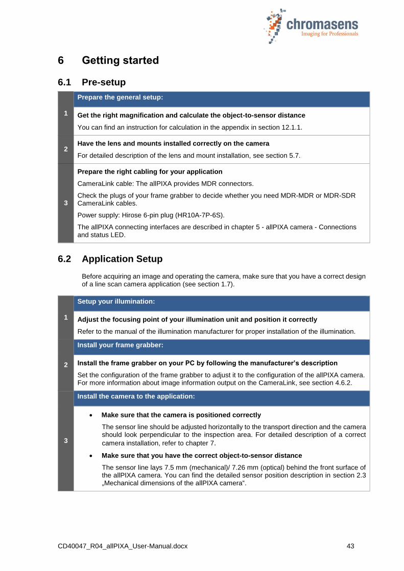
CD40047_R04_allPIXA_User-Manual.docx 43
6 Getting started
6.1 Pre-setup
1
Prepare the general setup:
Get the right magnification and calculate the object-to-sensor distance
You can find an instruction for calculation in the appendix in section 12.1.1.
2 Have the lens and mounts installed correctly on the camera
For detailed description of the lens and mount installation, see section 5.7.
3
Prepare the right cabling for your application
CameraLink cable: The allPIXA provides MDR connectors.
Check the plugs of your frame grabber to decide whether you need MDR-MDR or MDR-SDR CameraLink cables.
Power supply: Hirose 6-pin plug (HR10A-7P-6S).
The allPIXA connecting interfaces are described in chapter 5 - allPIXA camera - Connections and status LED.
6.2 Application Setup
Before acquiring an image and operating the camera, make sure that you have a correct design of a line scan camera application (see section 1.7).
1
Setup your illumination:
Adjust the focusing point of your illumination unit and position it correctly
Refer to the manual of the illumination manufacturer for proper installation of the illumination.
2
Install your frame grabber:
Install the frame grabber on your PC by following the manufacturer’s description
Set the configuration of the frame grabber to adjust it to the configuration of the allPIXA camera. For more information about image information output on the CameraLink, see section 4.6.2.
3
Install the camera to the application:
Make sure that the camera is positioned correctly
The sensor line should be adjusted horizontally to the transport direction and the camera should look perpendicular to the inspection area. For detailed description of a correct
camera installation, refer to chapter 7.
Make sure that you have the correct object-to-sensor distance
The sensor line lays 7.5 mm (mechanical)/ 7.26 mm (optical) behind the front surface of the allPIXA camera. You can find the detailed sensor position description in section 2.3 „Mechanical dimensions of the allPIXA camera“.

CD40047_R04_allPIXA_User-Manual.docx 44
6.3 Setting the system into operational state
1
Connect to the camera:
Connect the allPIXA camera to the frame grabber (section 0)
Connect the allPIXA camera to a suitable power supply (24 VDC +/- 10 %; 1A; typical 16 W)
2
Set into operational state:
Parameters of the camera are edited and set by using the CST.
Turn on the illumination and the camera.
Install CST (Camera setup tool) (see chapter 8).
Run CST and select the correct port to connect with the camera. (see section 8.3).
On the toolbar, click Show settings and then click Output format.
Set the correct CameraLink configuration and the connection speed.
Click Transfer setting to camera to save the setting into volatile memory.
Now, you should see an image in your frame grabber tool and may focus the camera.
Proceed to section 6.4 to calibrate the camera and to adjust the camera settings to your operating condition.
(You may select the User level in the system settings in section 9.14)
NOTE If you change a parameter, always click Transfer setting to camera on the toolbar or press F9 afterward to transfer the settings to volatile memory!
Click Burn setting permanently or press F10 to burn the setting into the camera!
Other buttons of the toolbar are described in section 9.1.
6.4 Adjusting the camera settings to your operating condition
Set the camera to free-running mode (Disable encoder and/or frame trigger).
Place a white reference that covers the whole scanning range in front of the camera.
NOTE
The white reference target has to be placed into the best focus plane of the camera. Therefore any features on its surface (for example dust or scratches) end up in the calibration profile of the camera. To avoid this if you use a static (non-moving) white reference target, use a clean white ceramic or plastic material, not paper. Ideally, the white object should move during the calibration process because the movement results in an averaging process and the camera diminishes the effects on any small variation in the white reference.
You can find the most important parameters and functions on the simple setup page (see section 10.1).
To calibrate the camera setting to your operating condition, follow the steps below:
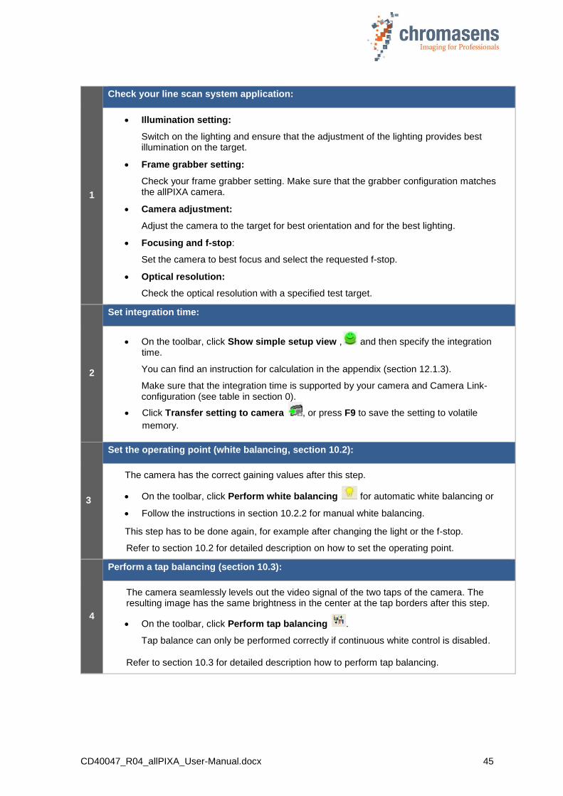
CD40047_R04_allPIXA_User-Manual.docx 45
1
Check your line scan system application:
Illumination setting:
Switch on the lighting and ensure that the adjustment of the lighting provides best illumination on the target.
Frame grabber setting:
Check your frame grabber setting. Make sure that the grabber configuration matches the allPIXA camera.
Camera adjustment:
Adjust the camera to the target for best orientation and for the best lighting.
Focusing and f-stop:
Set the camera to best focus and select the requested f-stop.
Optical resolution:
Check the optical resolution with a specified test target.
2
Set integration time:
On the toolbar, click Show simple setup view , and then specify the integration time.
You can find an instruction for calculation in the appendix (section 12.1.3).
Make sure that the integration time is supported by your camera and Camera Link-configuration (see table in section 0).
Click Transfer setting to camera , or press F9 to save the setting to volatile
memory.
3
Set the operating point (white balancing, section 10.2):
The camera has the correct gaining values after this step.
On the toolbar, click Perform white balancing for automatic white balancing or
Follow the instructions in section 10.2.2 for manual white balancing.
This step has to be done again, for example after changing the light or the f-stop.
Refer to section 10.2 for detailed description on how to set the operating point.
4
Perform a tap balancing (section 10.3):
The camera seamlessly levels out the video signal of the two taps of the camera. The resulting image has the same brightness in the center at the tap borders after this step.
On the toolbar, click Perform tap balancing .
Tap balance can only be performed correctly if continuous white control is disabled.
Refer to section 10.3 for detailed description how to perform tap balancing.

CD40047_R04_allPIXA_User-Manual.docx 46
5
Generate black-level reference (section 10.4):
On the toolbar, click Start reference wizard .
Click Black (offset) level reference and Create reference internally.
Click Next , and follow the instructions of the wizard.
On the toolbar, click Show simple setup view , and then select the Activate offset
correction check box.
Click Transfer setting to camera , to save the setting to volatile memory.
For information about creation of a black-level reference, see section 10.4.
6
Generate the shading reference / flat-field correction (section 10.5):
On the toolbar, click Start reference wizard , and follow the description in section
10.5.
On the toolbar, click Show simple setup view , and then select the Activate white-
level (flat-field) correction check box.
For information about creation of a shading reference, see section 10.5.
7
Save the settings:
On the toolbar, click Burn setting permanently to save settings into the camera
permanently.
You may choose different settings ( ) to configure your system to different applications. You can create backups by saving the setting into another setting (section 9.6), or by saving the settings to disk (section 9.9).
NOTE By selecting another setting, changes that have not been saved permanently
into the camera are lost
6.5 Digital processing and digital line trigger
1
Add image processing functions:
You can add digital image processing functions. Study the section 11.10 onward to find out which image processing functions are offered by the allPIXA.
2
Set the line trigger or encoder functions:
Connect the encoder or line trigger with the frame grabber or directly with the camera. If the encoder is connected to the frame grabber, make sure that the signal is transferred to CC1 or CC2.
Define the correct input signal port for the signals.
Click Show encoder setup to open the Encoder setup page (see section11.16).
Set the parameters in CST for the encoder or line trigger mode.

CD40047_R04_allPIXA_User-Manual.docx 47
7 Installing the allPIXA camera
7.1 Mechanical installation
Various mounting options are provided by the allPIXA camera housing. Due to its numerous threaded holes for attachment, the installation of the allPIXA camera is very simple and versatile.
Figure 26: Mechanical connection points of the allPIXA camera
The allPIXA camera is equipped with four fastening points on each side and its front with M4 threads (use maximum torque for full use of 6mm threat of 4 Nm).
For more information about the exact dimensions, see section 2.3 “Technical Data”.
7.2 Thermal links / cooling
The camera works within the defined temperature range (see section 2.4). To this purpose, it has to be mounted to thermally conductive parts on a wide and flat surface. A thermal connection to heat-conductive parts has a positive effect on operation of the allPIXA camera.
To dissipate the heat more effectively to the surrounding area, we also recommend to use heat conduction pads between the allPIXA camera and heat-conductive parts. You can also cool the allPIXA camera with passive heat sinks (cooling fins) or by active fan which should be directed at a large surface area of the allPIXA camera.
If questions are left, or if you are not sure how to adapt the allPIXA wave camera most effectively to its ambient conditions, do not hesitate to contact our support team.
7.3 Preventing installation errors
To ensure a high image and color quality, it is essential to align the camera correctly with the conveyor belt.
If the camera is misaligned, image artifacts may result.
Conveyor belt tracking
Make sure that the conveyor belt, on which the object is transported, runs completely straight.
In the left-hand section of Figure 27 you can see the optimum tracking of the conveyor belt, that means the conveyor belt runs completely straight. The enlarged view shows that each of the 3 pixels highlighted in black acquires the same point on the object.
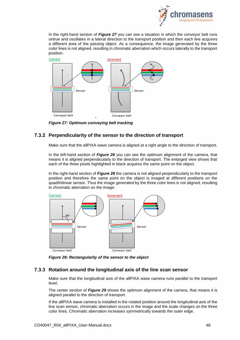
CD40047_R04_allPIXA_User-Manual.docx 48
In the right-hand section of Figure 27 you can see a situation in which the conveyor belt runs untrue and oscillates in a lateral direction to the transport position and then each line acquires a different area of the passing object. As a consequence, the image generated by the three color lines is not aligned, resulting in chromatic aberration which occurs laterally to the transport position.
Figure 27: Optimum conveying belt tracking
Perpendicularity of the sensor to the direction of transport
Make sure that the allPIXA wave camera is aligned at a right angle to the direction of transport.
In the left-hand section of Figure 28 you can see the optimum alignment of the camera, that means it is aligned perpendicularly to the direction of transport. The enlarged view shows that each of the three pixels highlighted in black acquires the same point on the object.
In the right-hand section of Figure 28 the camera is not aligned perpendicularly to the transport position and therefore the same point on the object is imaged at different positions on the quad/trilinear sensor. Thus the image generated by the three color lines is not aligned, resulting in chromatic aberration on the image:
Figure 28: Rectangularity of the sensor to the object
Rotation around the longitudinal axis of the line scan sensor
Make sure that the longitudinal axis of the allPIXA wave camera runs parallel to the transport level.
The center section of Figure 29 shows the optimum alignment of the camera, that means it is aligned parallel to the direction of transport.
If the allPIXA wave camera is installed in the rotated position around the longitudinal axis of the line scan sensor, chromatic aberration occurs in the image and the scale changes on the three color lines. Chromatic aberration increases symmetrically towards the outer edge.

CD40047_R04_allPIXA_User-Manual.docx 49
Figure 29: Rotation around the longitudinal axis of the line sensor
To obtain the best results, try to avoid the error shown in the above figure.
If it is not possible to place the camera in the best orientation, the allPIXA camera offers the “Keystone correction” function. If you use the Keystone correction function, the allPIXA camera is able to correct this error. For more information about keystone correction, see section 11.10.6.
Rotation around the transverse axis of the line sensor
Make sure that the transverse axis of the allPIXA wave camera runs parallel to the transport level. In the center section of Figure 30 you can see the optimum alignment of the camera, that means it is aligned parallel to the direction of transport.
If the allPIXA wave camera is installed in a rotated position around the transverse axis of the line scan sensor, this results in a chromatic aberration laterally to the direction of transport, and the size and color changes in relation to the angle.
Figure 30: Rotation around the transverse axis of the line scan sensor

CD40047_R04_allPIXA_User-Manual.docx 50
Alignment of the allPIXA camera
Exact alignment of the allPIXA camera is necessary for many applications, for example, if you use several allPIXA cameras in parallel.
The following section describes a simple method for exact alignment of the allPIXA camera.
Figure 31: Alignment of the allPIXA camera
In that case the static reference is the scanned object of which the camera is to be aligned including one vertical and one steadily rising straight line. These two straight lines intersect in the set position of the green color channel; prerequisite is that the lines are continually acquired (free-running mode) and the reference should no longer be moved.
Each line then achieves the same position and the angled line is acquired as a result of spacing the sensor lines of the color lines in different positions which results in colored lines in the image. The vertical center line produces a black line in the image, therefore, the center of the colored lines and the black line have to be aligned.
Left-hand marker Right-hand marker
Correct alignment
Incorrect alignment – too low
Incorrect alignment – rotated
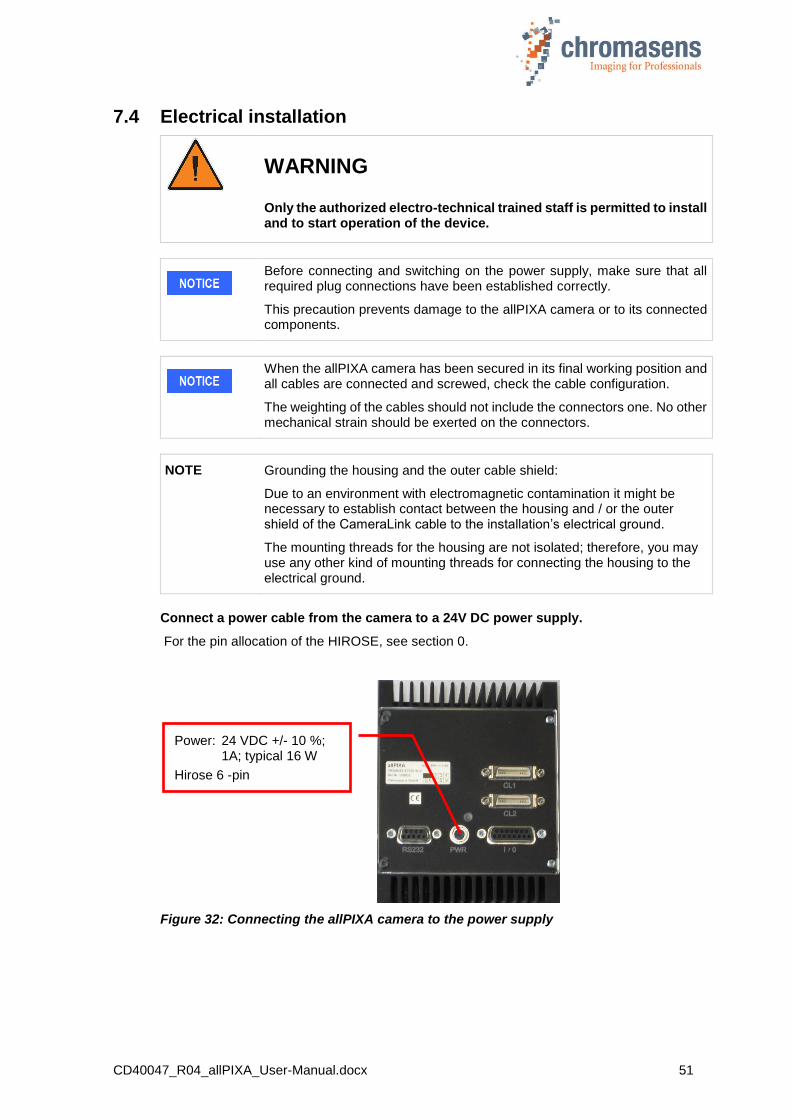
CD40047_R04_allPIXA_User-Manual.docx 51
7.4 Electrical installation
WARNING
Only the authorized electro-technical trained staff is permitted to install and to start operation of the device.
Before connecting and switching on the power supply, make sure that all required plug connections have been established correctly.
This precaution prevents damage to the allPIXA camera or to its connected components.
When the allPIXA camera has been secured in its final working position and all cables are connected and screwed, check the cable configuration.
The weighting of the cables should not include the connectors one. No other mechanical strain should be exerted on the connectors.
NOTE Grounding the housing and the outer cable shield:
Due to an environment with electromagnetic contamination it might be necessary to establish contact between the housing and / or the outer shield of the CameraLink cable to the installation’s electrical ground.
The mounting threads for the housing are not isolated; therefore, you may use any other kind of mounting threads for connecting the housing to the electrical ground.
Connect a power cable from the camera to a 24V DC power supply.
For the pin allocation of the HIROSE, see section 0.
Figure 32: Connecting the allPIXA camera to the power supply
Power: 24 VDC +/- 10 %; 1A; typical 16 W
Hirose 6 -pin

CD40047_R04_allPIXA_User-Manual.docx 52
7.5 Connecting the camera to the PC
The camera is connected to the PC by a CameraLink cable to the PC.
NOTE CameraLink cables are supplied ready-for-use in different lengths varying from 1 m to 10 m. You require a 26-pin MDR mini-D ribbon (male) connector for connection to the allPIXA camera.
Camera Link specification limits cable length to at most 6 m for a pixel clock of 85 MHz. The setup of camera, cable and frame grabber have to be tested in advance.
1. Connect the Camera Link cable:
o Camera Link Port 1 or 1+2 of the allPIXA wave camera (Port 1+2 support full data rate. Take notice that only with port 1 the half data rate is supported).
o Frame grabber installed in the PC.
NOTE Take care to connect the first port of the camera with the first port of the frame grabber.
Changing this might cause a switch between front and rear tap, some frame grabbers only offer the serial connection through the first port.
Figure 1: Connecting the allPIXA camera to a PC
Port 1 (with serial connection)
Port 2

CD40047_R04_allPIXA_User-Manual.docx 53
8 Installing the Camera Setup Tool (CST)
8.1 System Requirements
Microsoft Windows 7, Windows 8.1, Windows, 10 32 bit or 64 bit.
PC with a “Camera Link” Frame Grabber and optionally a serial interface RS232
8.2 Installing the CST Software
To install the CST software on your PC:
1. Start the setup program.
2. If the operating system is a 64 bit version, the Version selector page is shown:
In this case, select the version that should be installed, and then click Next.
The Select Destination Location page is shown:
3. Select the folder in which the CST software should be installed and then click Next.
The Select Start Menu Folder page is shown:
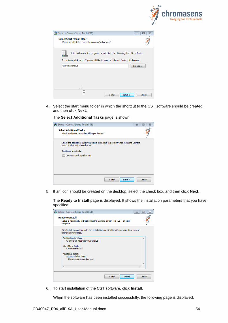
CD40047_R04_allPIXA_User-Manual.docx 54
4. Select the start menu folder in which the shortcut to the CST software should be created, and then click Next.
The Select Additional Tasks page is shown:
5. If an icon should be created on the desktop, select the check box, and then click Next.
The Ready to Install page is displayed. It shows the installation parameters that you have specified:
6. To start installation of the CST software, click Install.
When the software has been installed successfully, the following page is displayed:

CD40047_R04_allPIXA_User-Manual.docx 55
The CST software is now ready for use.
8.3 Establishing communication between camera and PC
This paragraph describes basic settings of the CST software that are used to establish communication between PC and camera. When you have specified these parameters, you can configure the camera.
To establish communication between camera and PC:
1. Double-click the CST icon on the PC desktop.
The Set interface parameters dialog box is shown:
2. Select the PC interface for the communication either via Camera Link or external serial port.
3. In the Baud rate list, click the desired baud rate for communication.
Alternatively, select the Use max. Baud rate check box to start automatic setup of the baud rate. CST and the allPIXA camera then determine the fastest possible baud rate up to 115 kBaud. If the frame grabber/interface does not support 115 kBaud, clear the Use max. Baud rate check box.
The default baud rate is 19.2 kBaud.
4. Click OK.
The CST software now establishes communication to the camera:
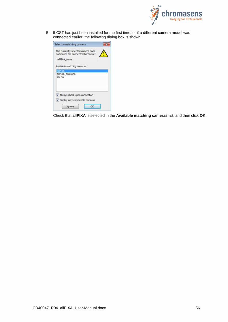
CD40047_R04_allPIXA_User-Manual.docx 56
5. If CST has just been installed for the first time, or if a different camera model was connected earlier, the following dialog box is shown:
Check that allPIXA is selected in the Available matching cameras list, and then click OK.

CD40047_R04_allPIXA_User-Manual.docx 57
9 CST program window
The CST program window comprises 5 areas:
Toolbar: Direct access to functions and data (section.9.1)
Menu bar: Access to all functions (section. 9.2)
Parameter view: Displaying the data
Status bar: Displaying the status of the connection
Message view
9.1 Toolbar
The toolbar for the CST provides the following functions:
Figure 2: CST Toolbar
Button Function
Load setting from file
Save setting to file
F9 Transfer setting to camera
F10 Burn setting permanently
Reset camera. Take notice that the parts for signal and image processing are not restarted with this button!
Menu bar (9.2)
Message view
Status bar
Toolbar (9.1)
Parameter view
Command log view
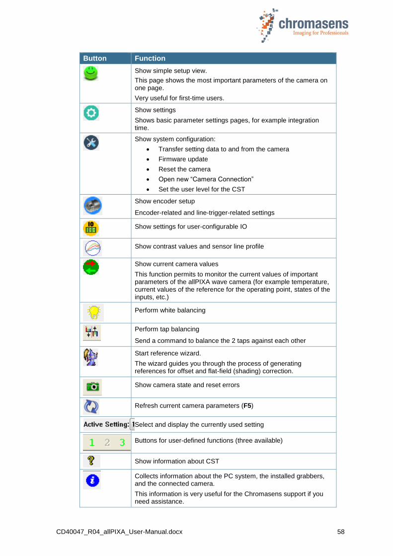
CD40047_R04_allPIXA_User-Manual.docx 58
Button Function
Show simple setup view.
This page shows the most important parameters of the camera on one page.
Very useful for first-time users.
Show settings
Shows basic parameter settings pages, for example integration time.
Show system configuration:
Transfer setting data to and from the camera
Firmware update
Reset the camera
Open new “Camera Connection”
Set the user level for the CST
Show encoder setup
Encoder-related and line-trigger-related settings
Show settings for user-configurable IO
Show contrast values and sensor line profile
Show current camera values
This function permits to monitor the current values of important parameters of the allPIXA wave camera (for example temperature, current values of the reference for the operating point, states of the inputs, etc.)
Perform white balancing
Perform tap balancing
Send a command to balance the 2 taps against each other
Start reference wizard.
The wizard guides you through the process of generating references for offset and flat-field (shading) correction.
Show camera state and reset errors
Refresh current camera parameters (F5)
Select and display the currently used setting
Buttons for user-defined functions (three available)
Show information about CST
Collects information about the PC system, the installed grabbers, and the connected camera.
This information is very useful for the Chromasens support if you need assistance.
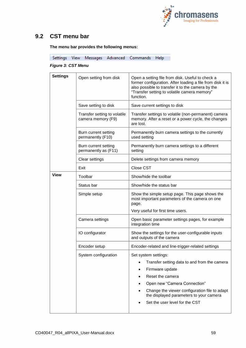
CD40047_R04_allPIXA_User-Manual.docx 59
9.2 CST menu bar
The menu bar provides the following menus:
Figure 3: CST Menu
Settings Open setting from disk Open a setting file from disk. Useful to check a former configuration. After loading a file from disk it is also possible to transfer it to the camera by the “Transfer setting to volatile camera memory” function.
Save setting to disk Save current settings to disk
Transfer setting to volatile camera memory (F9)
Transfer settings to volatile (non-permanent) camera memory. After a reset or a power cycle, the changes are lost.
Burn current setting permanently (F10)
Permanently burn camera settings to the currently used setting
Burn current setting permanently as (F11)
Permanently burn camera settings to a different setting
Clear settings Delete settings from camera memory
Exit Close CST
View
Toolbar Show/hide the toolbar
Status bar Show/hide the status bar
Simple setup Show the simple setup page. This page shows the most important parameters of the camera on one page.
Very useful for first time users.
Camera settings Open basic parameter settings pages, for example integration time
IO configurator Show the settings for the user-configurable inputs and outputs of the camera
Encoder setup Encoder-related and line-trigger-related settings
System configuration Set system settings:
Transfer setting data to and from the camera
Firmware update
Reset the camera
Open new “Camera Connection”
Change the viewer configuration file to adapt the displayed parameters to your camera
Set the user level for the CST

CD40047_R04_allPIXA_User-Manual.docx 60
View Current camera values Display current camera values such as voltages temperatures, gain values or similar.
This function permits to monitor the current values of important parameters of the allPIXA wave camera in live mode (for example the temperature or the current values of the reference for the operating point or the statuses of the inputs etc.)
Show line profile
Messages Arrange protocol views vertically
Arrange protocol views horizontally
Show command message view
Activates the command log view.
The communication data are logged here.
Clear logging views Clear the message view
Save logging views Save the message view to a log file for support cases and debugging the system.
Show detailed command views
Activates the command log view.
Additionally the communication data are logged in a more detailed way.
Advanced Register edit Open a dialog box for editing and reading registers directly on the camera.
Attention: Only for advanced users.
Bootstrap board For service only.
Get camera trace Return internal camera loggings. Might be requested by the Chromasens support to get detailed information about a possible problem.
Verify packet/setting This can be used to create consistent Setting or Firmware/FPGA packages. A checksum is generated for this Setting or Firmware package. As soon as something is changed here, the checksum is no longer consistent and this can be detected by the camera.
Create HIS checksum For development purposes only. If a value in an HSI-file changes, the checksum is longer valid. This function recalculates the checksum and updates the file.
Edit color conversion matrix
Opens a dialog box, which permits to edit the 4 color conversion matrixes saved inside the camera.
Set IP address If a connection to a GigE-camera should be established, the IP address can be set here
Get current camera state Opens a message box showing the camera state.
Restore factory setting Restore factory settings from internal camera memory.
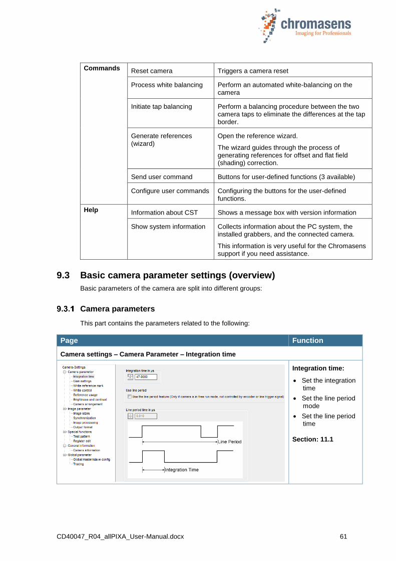
CD40047_R04_allPIXA_User-Manual.docx 61
Commands Reset camera Triggers a camera reset
Process white balancing Perform an automated white-balancing on the camera
Initiate tap balancing Perform a balancing procedure between the two camera taps to eliminate the differences at the tap border.
Generate references (wizard)
Open the reference wizard.
The wizard guides through the process of generating references for offset and flat field (shading) correction.
Send user command Buttons for user-defined functions (3 available)
Configure user commands Configuring the buttons for the user-defined functions.
Help Information about CST Shows a message box with version information
Show system information Collects information about the PC system, the installed grabbers, and the connected camera.
This information is very useful for the Chromasens support if you need assistance.
9.3 Basic camera parameter settings (overview)
Basic parameters of the camera are split into different groups:
Camera parameters
This part contains the parameters related to the following:
Page Function
Camera settings – Camera Parameter – Integration time
Integration time:
Set the integration time
Set the line period mode
Set the line period time
Section: 11.1
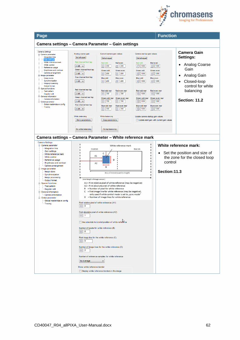
CD40047_R04_allPIXA_User-Manual.docx 62
Page Function
Camera settings – Camera Parameter – Gain settings
Camera Gain Settings:
Analog Coarse Gain
Analog Gain
Closed-loop control for white balancing
Section: 11.2
Camera settings – Camera Parameter – White reference mark
White reference mark:
Set the position and size of the zone for the closed loop control
Section:11.3
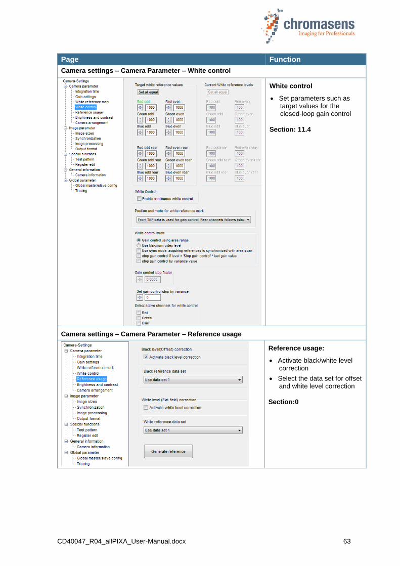
CD40047_R04_allPIXA_User-Manual.docx 63
Page Function
Camera settings – Camera Parameter – White control
White control
Set parameters such as target values for the closed-loop gain control
Section: 11.4
Camera settings – Camera Parameter – Reference usage
Reference usage:
Activate black/white level correction
Select the data set for offset and white level correction
Section:0
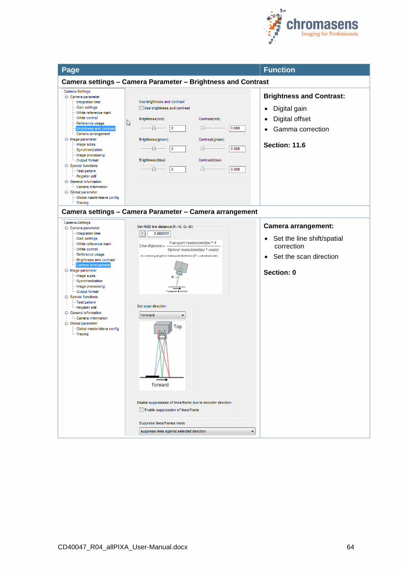
CD40047_R04_allPIXA_User-Manual.docx 64
Page Function
Camera settings – Camera Parameter – Brightness and Contrast
Brightness and Contrast:
Digital gain
Digital offset
Gamma correction
Section: 11.6
Camera settings – Camera Parameter – Camera arrangement
Camera arrangement:
Set the line shift/spatial correction
Set the scan direction
Section: 0
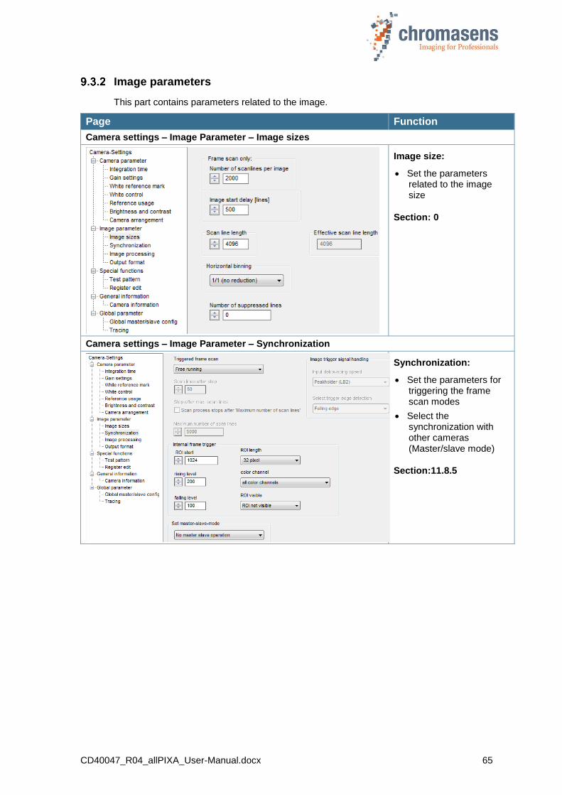
CD40047_R04_allPIXA_User-Manual.docx 65
Image parameters
This part contains parameters related to the image.
Page Function
Camera settings – Image Parameter – Image sizes
Image size:
Set the parameters related to the image size
Section: 0
Camera settings – Image Parameter – Synchronization
Synchronization:
Set the parameters for triggering the frame scan modes
Select the synchronization with other cameras (Master/slave mode)
Section:11.8.5
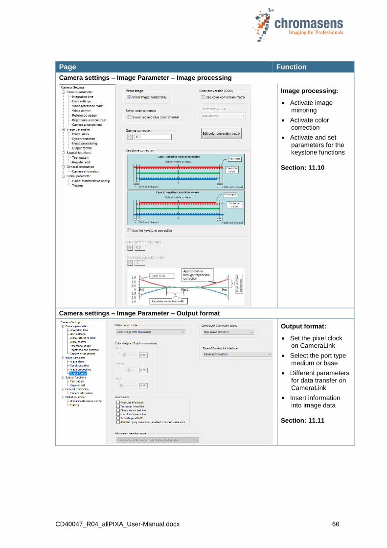
CD40047_R04_allPIXA_User-Manual.docx 66
Page Function
Camera settings – Image Parameter – Image processing
Image processing:
Activate image mirroring
Activate color correction
Activate and set parameters for the keystone functions
Section: 11.10
Camera settings – Image Parameter – Output format
Output format:
Set the pixel clock on CameraLink
Select the port type medium or base
Different parameters for data transfer on CameraLink
Insert information into image data
Section: 11.11
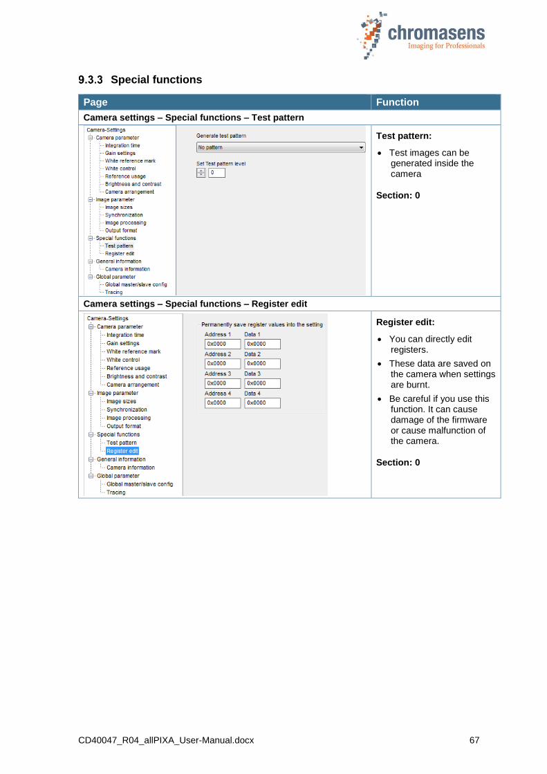
CD40047_R04_allPIXA_User-Manual.docx 67
Special functions
Page Function
Camera settings – Special functions – Test pattern
Test pattern:
Test images can be generated inside the camera
Section: 0
Camera settings – Special functions – Register edit
Register edit:
You can directly edit registers.
These data are saved on the camera when settings are burnt.
Be careful if you use this function. It can cause damage of the firmware or cause malfunction of the camera.
Section: 0
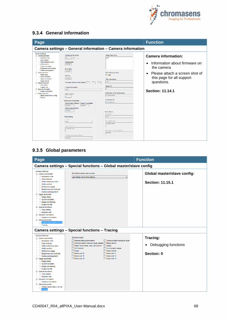
CD40047_R04_allPIXA_User-Manual.docx 68
General information
Page Function
Camera settings – General information – Camera information
Camera information:
Information about firmware on the camera
Please attach a screen shot of this page for all support questions.
Section: 11.14.1
Global parameters
Page Function
Camera settings – Special functions – Global master/slave config
Global master/slave config:
Section: 11.15.1
Camera settings – Special functions – Tracing
Tracing:
Debugging functions
Section: 0
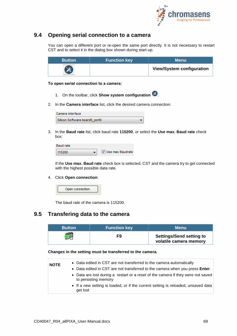
CD40047_R04_allPIXA_User-Manual.docx 69
9.4 Opening serial connection to a camera
You can open a different port or re-open the same port directly. It is not necessary to restart CST and to select it in the dialog box shown during start-up.
Button Function key Menu
View/System configuration
To open serial connection to a camera:
1. On the toolbar, click Show system configuration .
2. In the Camera interface list, click the desired camera connection:
3. In the Baud rate list, click baud rate 115200, or select the Use max. Baud rate check box:
If the Use max. Baud rate check box is selected, CST and the camera try to get connected with the highest possible data rate.
4. Click Open connection:
The baud rate of the camera is 115200.
9.5 Transfering data to the camera
Button Function key Menu
F9 Settings/Send setting to
volatile camera memory
Changes in the setting must be transferred to the camera.
NOTE Data edited in CST are not transferred to the camera automatically
Data edited in CST are not transferred to the camera when you press Enter.
Data are lost during a restart or a reset of the camera if they were not saved to persisting memory
If a new setting is loaded, or if the current setting is reloaded, unsaved data get lost

CD40047_R04_allPIXA_User-Manual.docx 70
9.6 Saving data to the camera permanently
Up to 18 different settings are available in the camera.
Setting 19 is reserved for the backup of the default setting.
We recommend to use settings 1 to 9 for working settings and setting 10 to 18 for backup settings.
The currently selected setting is displayed in the toolbar:
To save the data to the currently selected setting, use the following:
Button Function key Menu
F10 Settings/Burn current
setting permanently
To save the data to different setting in the camera, use the following:
Button Function key Menu
F11 Settings/Burn current setting permanently as
To save data to a different setting:
1. Press F11.
The Burn setting as dialog box is shown:
2. In the Burn setting as no list, click the desired setting number, and then click OK.
NOTE First, changes made inside CST must be transferred to the camera. If they are not transferred, they get lost. These functions take the data from the volatile memory in the camera for burning.
9.7 Refreshing data from the camera in CST
Some data have been changed in the camera or in the setting by the camera itself, for example by the closed-loop control for white balancing. To update the current data in CST, click the refresh button:
Button Function key Menu
F5
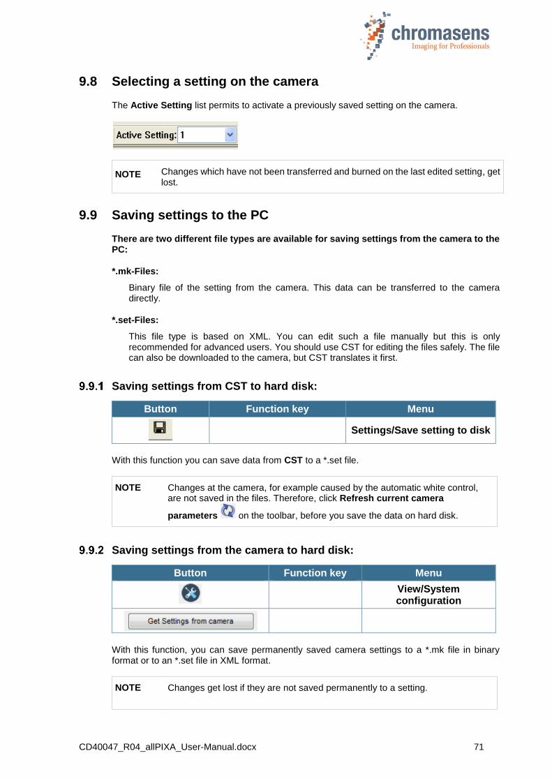
CD40047_R04_allPIXA_User-Manual.docx 71
9.8 Selecting a setting on the camera
The Active Setting list permits to activate a previously saved setting on the camera.
NOTE Changes which have not been transferred and burned on the last edited setting, get lost.
9.9 Saving settings to the PC
There are two different file types are available for saving settings from the camera to the PC:
*.mk-Files:
Binary file of the setting from the camera. This data can be transferred to the camera directly.
*.set-Files:
This file type is based on XML. You can edit such a file manually but this is only recommended for advanced users. You should use CST for editing the files safely. The file can also be downloaded to the camera, but CST translates it first.
Saving settings from CST to hard disk:
Button Function key Menu
Settings/Save setting to disk
With this function you can save data from CST to a *.set file.
NOTE Changes at the camera, for example caused by the automatic white control, are not saved in the files. Therefore, click Refresh current camera
parameters on the toolbar, before you save the data on hard disk.
Saving settings from the camera to hard disk:
Button Function key Menu
View/System configuration
With this function, you can save permanently saved camera settings to a *.mk file in binary format or to an *.set file in XML format.
NOTE Changes get lost if they are not saved permanently to a setting.

CD40047_R04_allPIXA_User-Manual.docx 72
To save camera settings to a file:
1. On the toolbar, click Show system configuration , and then click Save multiple settings to disk.
The Upload Settings dialog box opens and shows enabled check boxes for all available camera settings:
2. Specify the settings that should be saved by selecting or clearing check boxes as needed:
3. To specify the file name, enter path and file name in the Filename box, or click Browse to open a File dialog box.
4. To save the settings in binary format as *.mk file, click Save settings, or to save them in XML format as *.set file, click Export as XML.
Each selected setting is saved to a separate file, at which the setting number is appended to the file name.
9.10 Transferring saved settings from the PC to the camera
NOTE If you transfer settings to the camera, settings with the same number are overwritten.
There are two ways available for transferring settings to the camera:
Transfer settings directly to the camera
Open the setting in CST and transfer data in a second step to the camera.
1. Transferring settings with direct transfer:
Button Function key Menu
View/System
configuration
2. Transferring settings using CST:
Button Function key Menu
Settings/Open setting from disk
A standard file dialog box opens and you can select *.set files or *.mk files. The setting is then shown in CST, but it is not sent to the camera.
As next step, press F9 to send the setting to the camera. Then press F10 to burn the setting as setting 1, or press F11 to burn it to a setting with a different number.

CD40047_R04_allPIXA_User-Manual.docx 73
9.11 Deleting settings on the camera
You can delete burned settings on the camera.
Button Function key Menu
Settings/Clear settings
NOTE I It is not allowed to delete setting 1. If setting 1 has been changed erroneously, you can download the initial setting 1 to the camera. The required file is included in the software package, which is available for download. The file is called PIXAwaveXXXX_InitSetting1_FreeRun_Rnnn.mk . where XXXX is related to the allPIXA camera model and nnn is the revision of the firmware package.
Alternatively, you can restore the default setting 1 by clicking Restore factory settings on the Simple setup view, without having to deal with download packages. In this case, the setting is restored from internal camera memory.
NOTE II This function is only available if the User level has been set to Guru.
To delete settings on the camera:
1. On the Settings menu, click Clear settings.
2. In the Clear Settings dialog box, which shows enabled check boxes for all available camera settings, select check boxes as needed:
3. To delete the specified settings, click Clear.
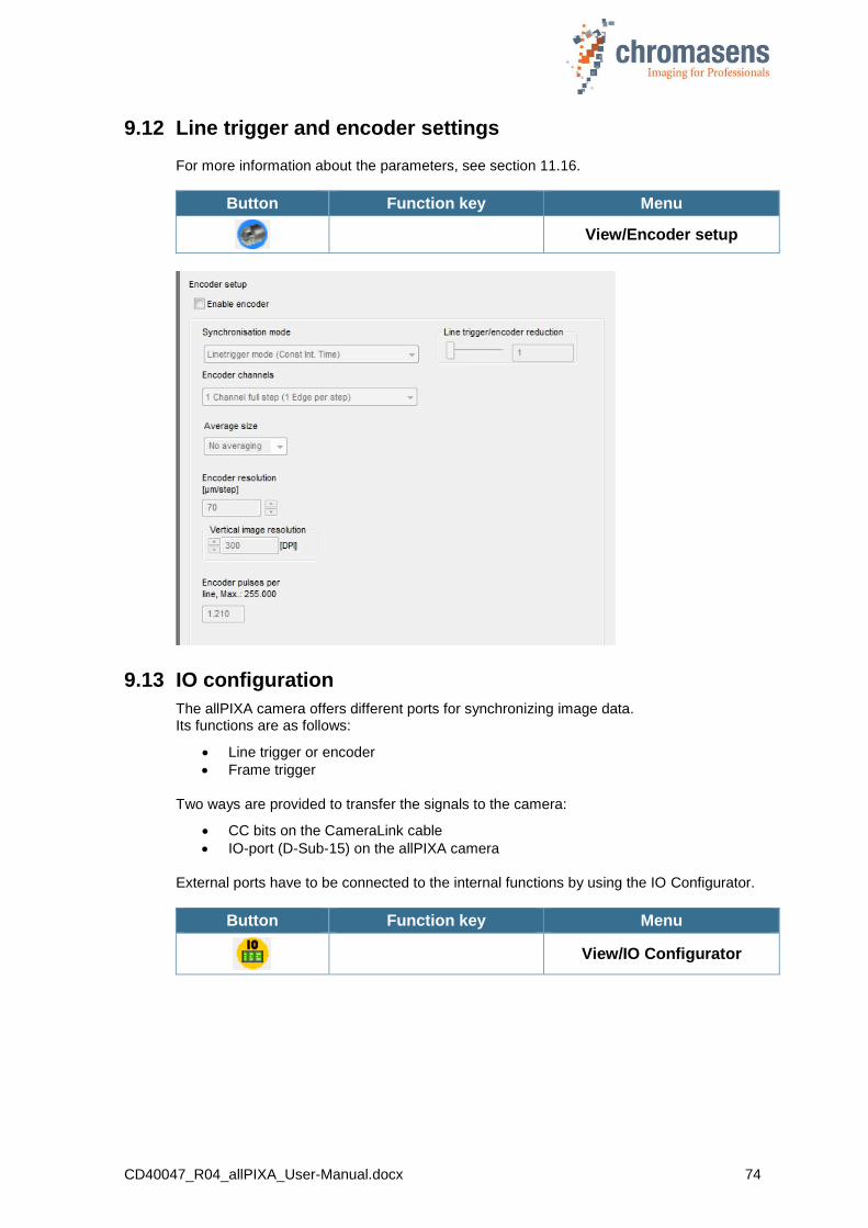
CD40047_R04_allPIXA_User-Manual.docx 74
9.12 Line trigger and encoder settings
For more information about the parameters, see section 11.16.
Button Function key Menu
View/Encoder setup
9.13 IO configuration
The allPIXA camera offers different ports for synchronizing image data. Its functions are as follows:
Line trigger or encoder
Frame trigger
Two ways are provided to transfer the signals to the camera:
CC bits on the CameraLink cable
IO-port (D-Sub-15) on the allPIXA camera
External ports have to be connected to the internal functions by using the IO Configurator.
Button Function key Menu
View/IO Configurator

CD40047_R04_allPIXA_User-Manual.docx 75
Avoid double use of internal functions (only select one input for line trigger or frame trigger)
To transfer the selection to the camera, click Transfer setting to camera on the toolbar, or press F9.
To save changes on the camera permanently, click Burn setting permanently on the toolbar, or click F10.
Encoder - enable increments setting
With the enable increments setting you can enable/disable the encoder input by using an external I/O Port (CC2 or CC4 of the CameraLink interface). This feature can be useful to enable the encoder in real time (for example applications with several cameras). The function is configured with the IO Configuration menu. If this feature is not used, the configuration must be set to default.
Line trigger inputs
Frame trigger inputs
Enable Line trigger inputs

CD40047_R04_allPIXA_User-Manual.docx 76
9.14 Setting the user level in CST
CST provides three different user levels. In Normal user level, several parameters and functions are not available, which helps to prevent undesired changes by inexperienced users. Only in Guru level, all features are available.
Button Function key Menu
View/System configuration
To switch to a different user level:
1. On the toolbar, click Show system configuration .
2. In the User level list, click the desired level:
NOTE We recommend to work with Normal user level as much as possible to avoid erroneous settings.
The following table shows which commands of the Advanced menu are enabled in the different user levels:
Name Normal User Expert Guru
Register Edit X
Bootstrap Board X
IO-Configurator X X (X)
Get Camera Trace X X
Verify Packet/Setting X
Clear Settings X
Edit Color Correction Matrix X
Get current camera state X X X
9.15 Resetting the camera
You can reset the camera from CST:
Button Function key Menu
View/System configuration
On the camera a reset is performed, and afterward CST is automatically re-connected to the camera.
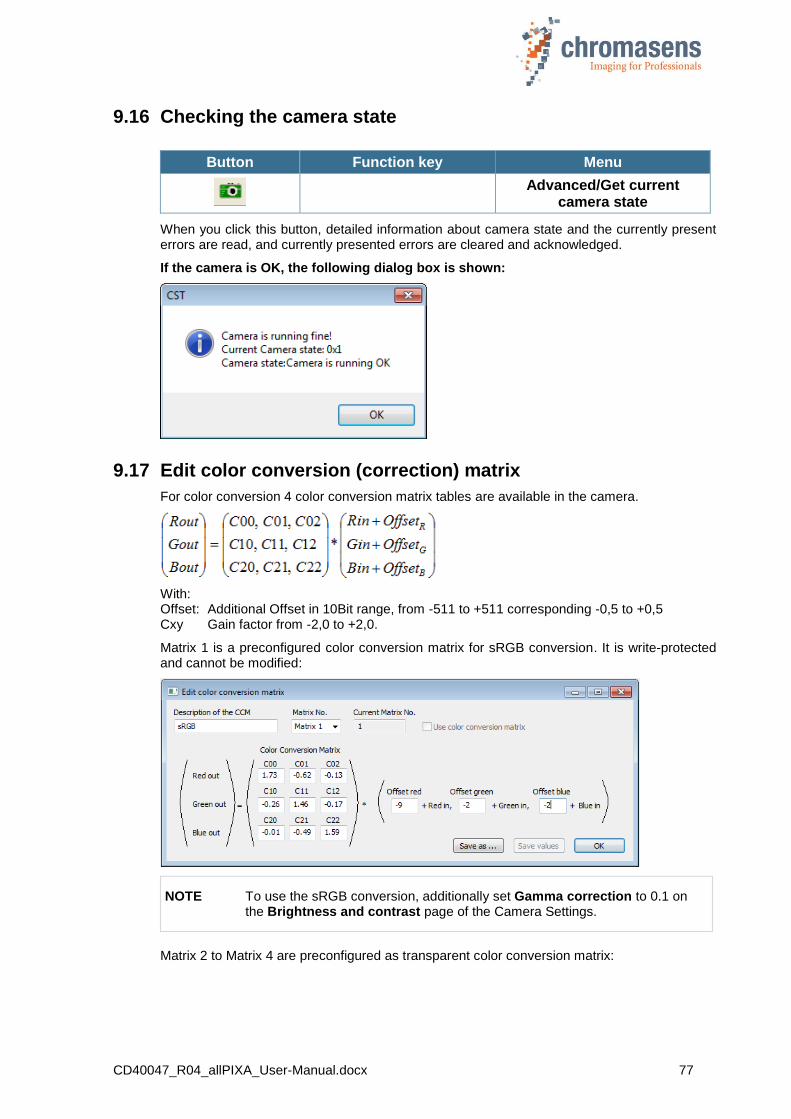
CD40047_R04_allPIXA_User-Manual.docx 77
9.16 Checking the camera state
Button Function key Menu
Advanced/Get current
camera state
When you click this button, detailed information about camera state and the currently present errors are read, and currently presented errors are cleared and acknowledged.
If the camera is OK, the following dialog box is shown:
9.17 Edit color conversion (correction) matrix
For color conversion 4 color conversion matrix tables are available in the camera.
With: Offset: Additional Offset in 10Bit range, from -511 to +511 corresponding -0,5 to +0,5 Cxy Gain factor from -2,0 to +2,0.
Matrix 1 is a preconfigured color conversion matrix for sRGB conversion. It is write-protected and cannot be modified:
NOTE To use the sRGB conversion, additionally set Gamma correction to 0.1 on the Brightness and contrast page of the Camera Settings.
Matrix 2 to Matrix 4 are preconfigured as transparent color conversion matrix:

CD40047_R04_allPIXA_User-Manual.docx 78
Matrix 2 to Matrix 4 can be modified.
To modify a matrix:
1. On the Advanced menu, click Edit color conversion matrix.
The Edit color conversion matrix dialog box opens and shows the values of Matrix 1.
2. In the Matrix No list, select the matrix whose values you want to modify.
3. Modify values, click Save as and select one of the matrixes Matrix 2 to Matrix 4.
4. If the currently selected matrix is not Matrix 1, you can alternatively click Save values to save the values to the currently selected matrix.
NOTE The command Edit color conversion matrix is only available in user mode Guru.
9.18 Choosing a different configuration file for the parameter display
You can modify the Parameter view of CST according to the camera type.
Button Function key Menu
View/System configuration
To switch to a different configuration file:
1. On the toolbar, click Show system configuration .
2. In the Select camera type list, click the respective item:
The default viewer configuration for the allPIXA wave camera is allPIXA_wave.
The changes are applied to the Parameter view immediately. The settings are stored in the registry, and CST uses the new viewer file when it is started next time.
According to the different viewer file, some parameters are visible or hidden.

CD40047_R04_allPIXA_User-Manual.docx 79
9.19 Register Edit
You can read and prepare registers in the camera.
Button Function key Menu
Advanced/Register edit
Compared to the register edit of the basic settings (section 0 “
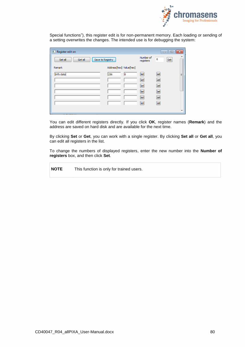
CD40047_R04_allPIXA_User-Manual.docx 80
Special functions”), this register edit is for non-permanent memory. Each loading or sending of a setting overwrites the changes. The intended use is for debugging the system:
You can edit different registers directly. If you click OK, register names (Remark) and the address are saved on hard disk and are available for the next time.
By clicking Set or Get, you can work with a single register. By clicking Set all or Get all, you can edit all registers in the list.
To change the numbers of displayed registers, enter the new number into the Number of registers box, and then click Set.
NOTE This function is only for trained users.

CD40047_R04_allPIXA_User-Manual.docx 81
10 allPIXA setup
To set up the allPIXA camera for an application, several parameter must be adapted. For example scan line period must fit transport speed of the scanned target. Or camera gain must be adapted to brightness of illumination. For all these parameters, a simple setup process is described here to get quick start of the camera in customer surrounding.
10.1 Simple setup for a fast ready-to-operate state
On the toolbar, click Display simple setup view to enter the simple setup page which comprises the most important parameters and functions on a single page.
The parameters are placed in a functional order to give you an orientation which parameters should be set first. Start with the topmost parameter.
NOTE If you change a parameter, always click Transfer setting to camera on the toolbar or press F9 afterward to transfer the settings to volatile memory! Click
Burn setting permanently or press F10 to burn the setting into the camera!
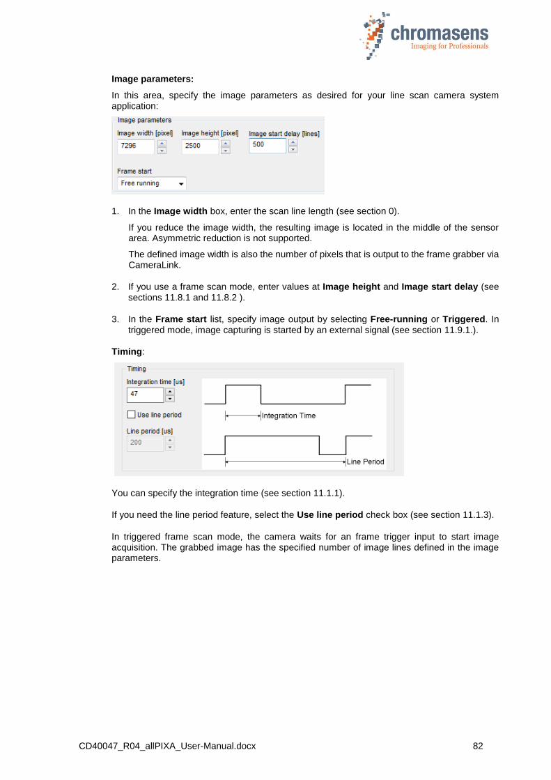
CD40047_R04_allPIXA_User-Manual.docx 82
Image parameters:
In this area, specify the image parameters as desired for your line scan camera system application:
1. In the Image width box, enter the scan line length (see section 0).
If you reduce the image width, the resulting image is located in the middle of the sensor area. Asymmetric reduction is not supported.
The defined image width is also the number of pixels that is output to the frame grabber via CameraLink.
2. If you use a frame scan mode, enter values at Image height and Image start delay (see sections 11.8.1 and 11.8.2 ).
3. In the Frame start list, specify image output by selecting Free-running or Triggered. In triggered mode, image capturing is started by an external signal (see section 11.9.1.).
Timing:
You can specify the integration time (see section 11.1.1).
If you need the line period feature, select the Use line period check box (see section 11.1.3).
In triggered frame scan mode, the camera waits for an frame trigger input to start image acquisition. The grabbed image has the specified number of image lines defined in the image parameters.
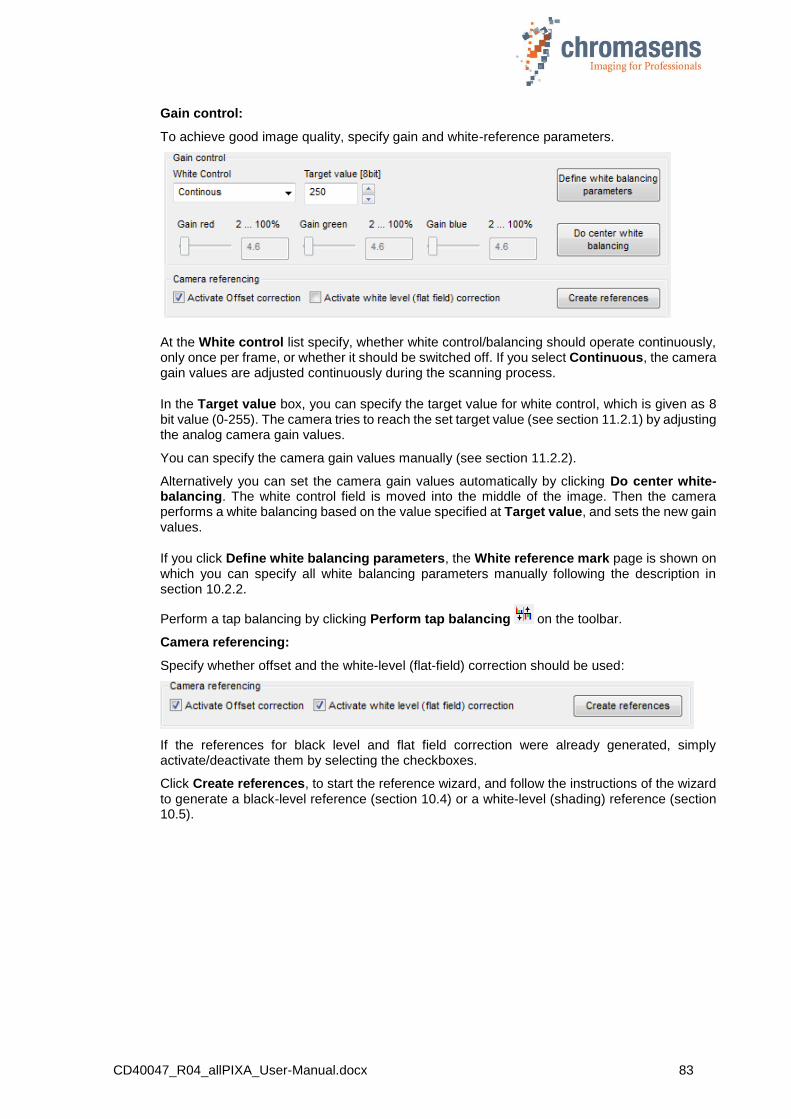
CD40047_R04_allPIXA_User-Manual.docx 83
Gain control:
To achieve good image quality, specify gain and white-reference parameters.
At the White control list specify, whether white control/balancing should operate continuously, only once per frame, or whether it should be switched off. If you select Continuous, the camera gain values are adjusted continuously during the scanning process.
In the Target value box, you can specify the target value for white control, which is given as 8 bit value (0-255). The camera tries to reach the set target value (see section 11.2.1) by adjusting the analog camera gain values.
You can specify the camera gain values manually (see section 11.2.2).
Alternatively you can set the camera gain values automatically by clicking Do center white-balancing. The white control field is moved into the middle of the image. Then the camera performs a white balancing based on the value specified at Target value, and sets the new gain values.
If you click Define white balancing parameters, the White reference mark page is shown on which you can specify all white balancing parameters manually following the description in section 10.2.2.
Perform a tap balancing by clicking Perform tap balancing on the toolbar.
Camera referencing:
Specify whether offset and the white-level (flat-field) correction should be used:
If the references for black level and flat field correction were already generated, simply activate/deactivate them by selecting the checkboxes.
Click Create references, to start the reference wizard, and follow the instructions of the wizard to generate a black-level reference (section 10.4) or a white-level (shading) reference (section 10.5).
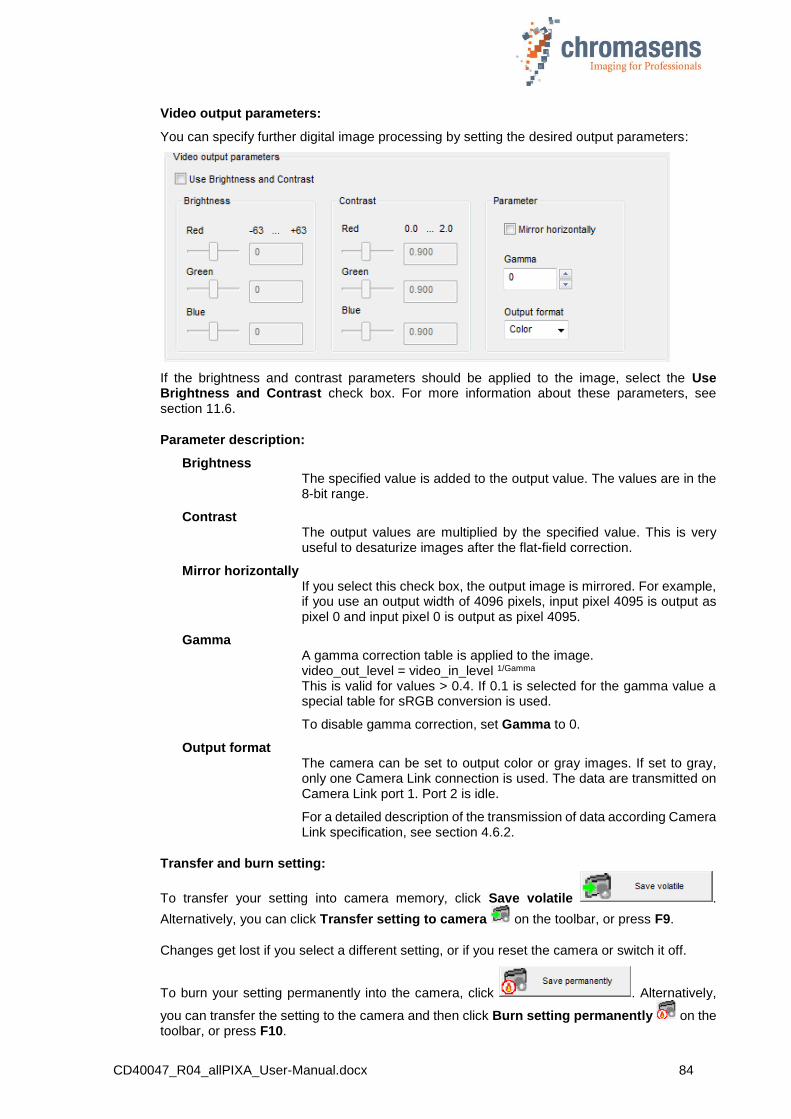
CD40047_R04_allPIXA_User-Manual.docx 84
Video output parameters:
You can specify further digital image processing by setting the desired output parameters:
If the brightness and contrast parameters should be applied to the image, select the Use Brightness and Contrast check box. For more information about these parameters, see section 11.6.
Parameter description:
Brightness The specified value is added to the output value. The values are in the 8-bit range.
Contrast The output values are multiplied by the specified value. This is very useful to desaturize images after the flat-field correction.
Mirror horizontally If you select this check box, the output image is mirrored. For example, if you use an output width of 4096 pixels, input pixel 4095 is output as pixel 0 and input pixel 0 is output as pixel 4095.
Gamma A gamma correction table is applied to the image. video_out_level = video_in_level 1/Gamma
This is valid for values > 0.4. If 0.1 is selected for the gamma value a special table for sRGB conversion is used.
To disable gamma correction, set Gamma to 0.
Output format The camera can be set to output color or gray images. If set to gray, only one Camera Link connection is used. The data are transmitted on Camera Link port 1. Port 2 is idle.
For a detailed description of the transmission of data according Camera Link specification, see section 4.6.2.
Transfer and burn setting:
To transfer your setting into camera memory, click Save volatile .
Alternatively, you can click Transfer setting to camera on the toolbar, or press F9.
Changes get lost if you select a different setting, or if you reset the camera or switch it off.
To burn your setting permanently into the camera, click . Alternatively,
you can transfer the setting to the camera and then click Burn setting permanently on the toolbar, or press F10.
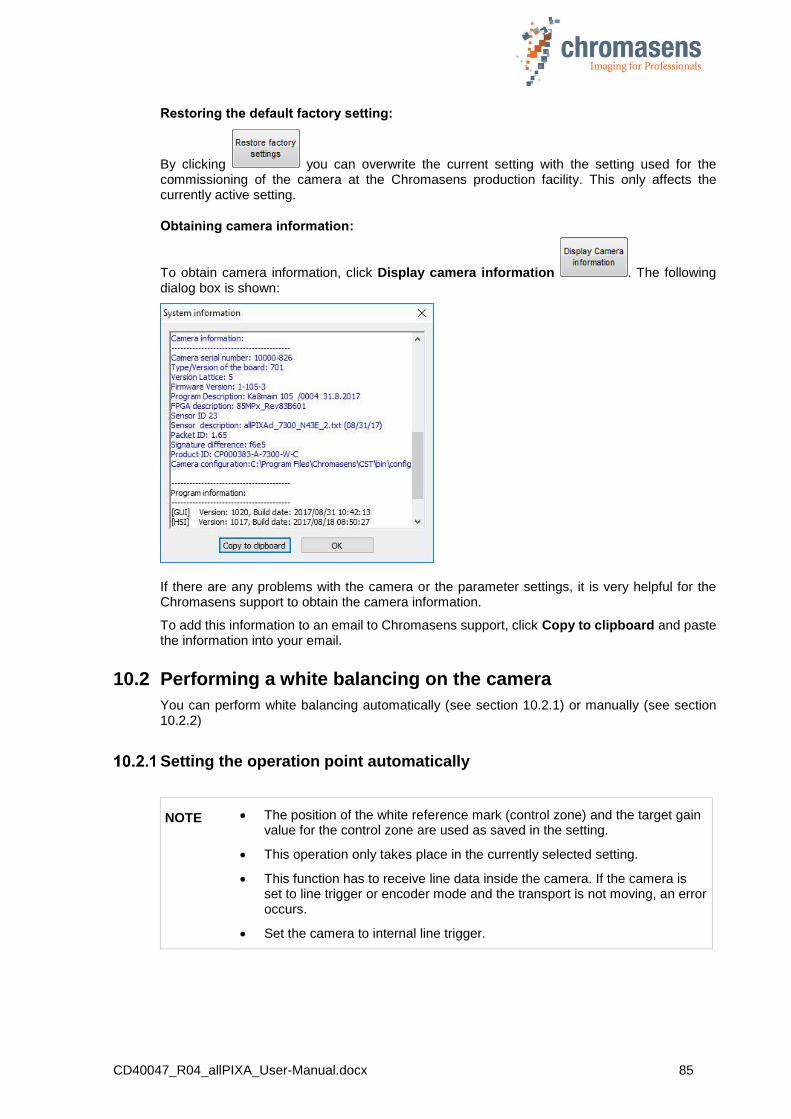
CD40047_R04_allPIXA_User-Manual.docx 85
Restoring the default factory setting:
By clicking you can overwrite the current setting with the setting used for the commissioning of the camera at the Chromasens production facility. This only affects the currently active setting.
Obtaining camera information:
To obtain camera information, click Display camera information . The following dialog box is shown:
If there are any problems with the camera or the parameter settings, it is very helpful for the Chromasens support to obtain the camera information.
To add this information to an email to Chromasens support, click Copy to clipboard and paste the information into your email.
10.2 Performing a white balancing on the camera
You can perform white balancing automatically (see section 10.2.1) or manually (see section 10.2.2)
Setting the operation point automatically
NOTE The position of the white reference mark (control zone) and the target gain value for the control zone are used as saved in the setting.
This operation only takes place in the currently selected setting.
This function has to receive line data inside the camera. If the camera is set to line trigger or encoder mode and the transport is not moving, an error occurs.
Set the camera to internal line trigger.

CD40047_R04_allPIXA_User-Manual.docx 86
1
Prepare the setup for the operation.
Stop the transport
Place a white reference target in front of the camera
Set the camera to free-running mode (disable encoder and/or frame trigger)
Enable the black-level correction
Optional:
Start an image acquisition with the frame grabber to control the result.
2 On the toolbar, click Perform white balancing .
3
In the appearing dialog box, click Yes.
If process succeeds, White balancing succeeded appears in the message box.
Possible errors:
White balancing error occurred. Error code No: 0x10D: no reference data Camera is not in free-running mode, but there are no trigger signals and thus no reference data are available. Adapt your configuration accordingly.
White balancing error occurred. Error code No: 0xF6: maximum gain exceeded Digital gain value exceed internal limit. Increase analog coarse gain or increase illumination intensity.
White balancing error occurred. Error code No: 0x41: minimum gain exceeded Digital gain value has reached lower limit. Decrease analog coarse gain or reduce illumination intensity.
White balancing error occurred. Error code No: 0xF7: White balance cannot be leveled White balance process has exceeded time limit but up to now no error has occurred. White balance may last very long if white reference area is large, line period is high. Restart of white balance may finish the process successful.
4 On the toolbar, click Perform tap balancing .
5
In the appearing dialog box, click Yes to save the gain values permanently as start
values after performing tap balancing:
6
On the toolbar, click Refresh .
Optional:
Check the values of Current camera gain values, if necessary. It is recommended to keep the gaining values in the range of 80 to 200 for best image quality.
If the current gaining values are above 200, you can please increase Analog coarse gain and repeat from step 2. (For more information about analog coarse gain, see
section 11.2.1).
7 On the toolbar, click Burn setting permanently .
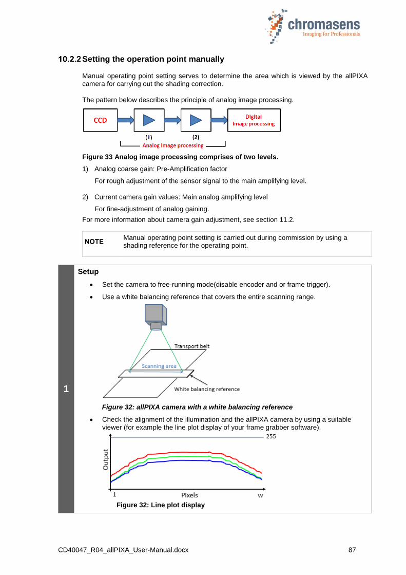
CD40047_R04_allPIXA_User-Manual.docx 87
Setting the operation point manually
Manual operating point setting serves to determine the area which is viewed by the allPIXA camera for carrying out the shading correction.
The pattern below describes the principle of analog image processing.
Figure 33 Analog image processing comprises of two levels.
1) Analog coarse gain: Pre-Amplification factor
For rough adjustment of the sensor signal to the main amplifying level.
2) Current camera gain values: Main analog amplifying level
For fine-adjustment of analog gaining.
For more information about camera gain adjustment, see section 11.2.
NOTE Manual operating point setting is carried out during commission by using a shading reference for the operating point.
1
Setup
Set the camera to free-running mode(disable encoder and or frame trigger).
Use a white balancing reference that covers the entire scanning range.
Figure 32: allPIXA camera with a white balancing reference
Check the alignment of the illumination and the allPIXA camera by using a suitable viewer (for example the line plot display of your frame grabber software).
Figure 32: Line plot display
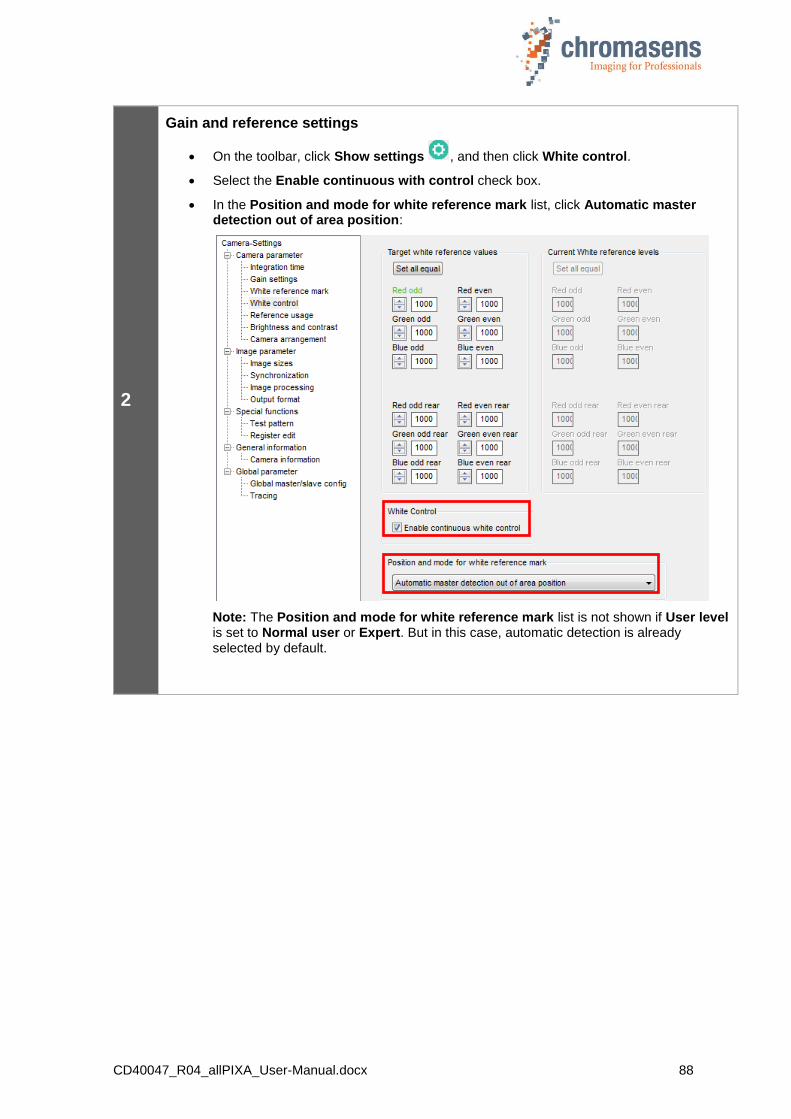
CD40047_R04_allPIXA_User-Manual.docx 88
2
Gain and reference settings
On the toolbar, click Show settings , and then click White control.
Select the Enable continuous with control check box.
In the Position and mode for white reference mark list, click Automatic master detection out of area position:
Note: The Position and mode for white reference mark list is not shown if User level is set to Normal user or Expert. But in this case, automatic detection is already selected by default.

CD40047_R04_allPIXA_User-Manual.docx 89
3
Selection and adjustment of the white reference mark on the white reference
Set the “White reference mark” to the brightest region in the image. In most cases, this is the center of the image.
Note:
The reference mark area may not include the TAP border. If the front and rear TAP are defined to be independent, the defined reference mark area is mirrored into the other TAP.
4 On the toolbar, click Transfer setting to camera , or press F9.
Current camera parameters are saved non-permanently in the camera.
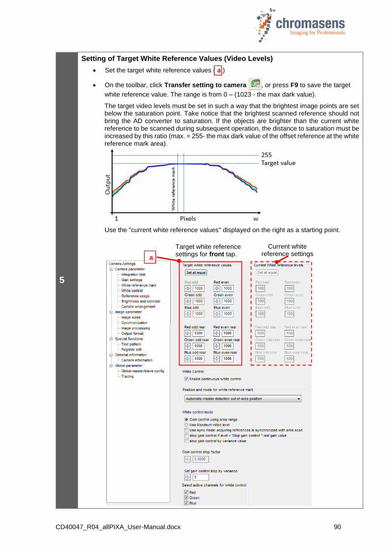
CD40047_R04_allPIXA_User-Manual.docx 90
5
Setting of Target White Reference Values (Video Levels)
Set the target white reference values ( a )
On the toolbar, click Transfer setting to camera , or press F9 to save the target
white reference value. The range is from 0 – (1023 - the max dark value).
The target video levels must be set in such a way that the brightest image points are set below the saturation point. Take notice that the brightest scanned reference should not bring the AD converter to saturation. If the objects are brighter than the current white reference to be scanned during subsequent operation, the distance to saturation must be increased by this ratio (max. = 255- the max dark value of the offset reference at the white reference mark area).
Use the “current white reference values" displayed on the right as a starting point.
Target white reference settings for front tap.
Current white reference settings
a
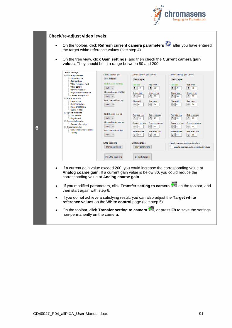
CD40047_R04_allPIXA_User-Manual.docx 91
6
Check/re-adjust video levels:
On the toolbar, click Refresh current camera parameters after you have entered the target white reference values (see step 4).
On the tree view, click Gain settings, and then check the Current camera gain values. They should be in a range between 80 and 200:
If a current gain value exceed 200, you could increase the corresponding value at Analog coarse gain. If a current gain value is below 80, you could reduce the corresponding value at Analog coarse gain.
If you modified parameters, click Transfer setting to camera on the toolbar, and then start again with step 6.
If you do not achieve a satisfying result, you can also adjust the Target white reference values on the White control page (see step 5)
On the toolbar, click Transfer setting to camera , or press F9 to save the settings non-permanently on the camera.

CD40047_R04_allPIXA_User-Manual.docx 92
7
Tap balancing
On the toolbar, click Perform tap balancing .
The values for the slave tap (= rear tap in the example shown below) are aligned with the master tap.
Click Refresh current camera parameters .
Example with the front tap as the master tap and the rear tap as the slave tap:
Target white reference
settings for front tap.
Target white reference settings
for rear tap.
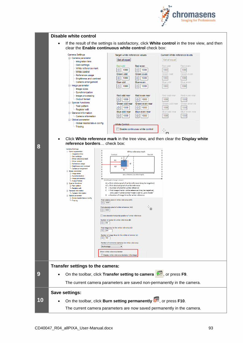
CD40047_R04_allPIXA_User-Manual.docx 93
8
Disable white control
If the result of the settings is satisfactory, click White control in the tree view, and then clear the Enable continuous white control check box:
Click White reference mark in the tree view, and then clear the Display white reference borders… check box:
9
Transfer settings to the camera:
On the toolbar, click Transfer setting to camera , or press F9.
The current camera parameters are saved non-permanently in the camera.
10
Save settings:
On the toolbar, click Burn setting permanently , or press F10.
The current camera parameters are now saved permanently in the camera.
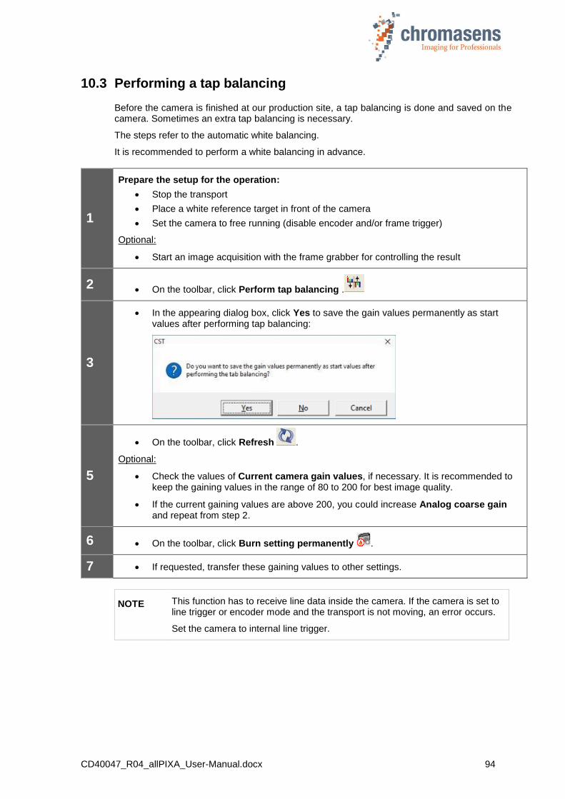
CD40047_R04_allPIXA_User-Manual.docx 94
10.3 Performing a tap balancing
Before the camera is finished at our production site, a tap balancing is done and saved on the camera. Sometimes an extra tap balancing is necessary.
The steps refer to the automatic white balancing.
It is recommended to perform a white balancing in advance.
1
Prepare the setup for the operation:
Stop the transport
Place a white reference target in front of the camera
Set the camera to free running (disable encoder and/or frame trigger)
Optional:
Start an image acquisition with the frame grabber for controlling the result
2 On the toolbar, click Perform tap balancing .
3
In the appearing dialog box, click Yes to save the gain values permanently as start values after performing tap balancing:
5
On the toolbar, click Refresh .
Optional:
Check the values of Current camera gain values, if necessary. It is recommended to keep the gaining values in the range of 80 to 200 for best image quality.
If the current gaining values are above 200, you could increase Analog coarse gain and repeat from step 2.
6 On the toolbar, click Burn setting permanently .
7 If requested, transfer these gaining values to other settings.
NOTE This function has to receive line data inside the camera. If the camera is set to line trigger or encoder mode and the transport is not moving, an error occurs.
Set the camera to internal line trigger.
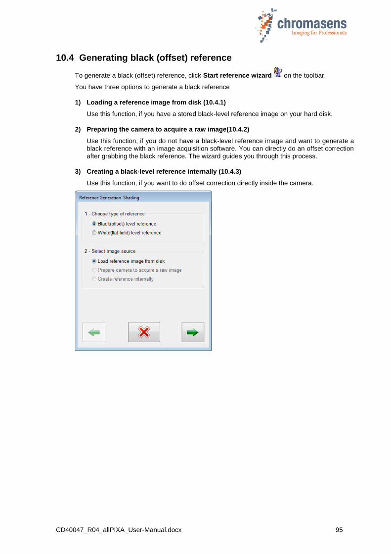
CD40047_R04_allPIXA_User-Manual.docx 95
10.4 Generating black (offset) reference
To generate a black (offset) reference, click Start reference wizard on the toolbar.
You have three options to generate a black reference
1) Loading a reference image from disk (10.4.1)
Use this function, if you have a stored black-level reference image on your hard disk.
2) Preparing the camera to acquire a raw image(10.4.2)
Use this function, if you do not have a black-level reference image and want to generate a black reference with an image acquisition software. You can directly do an offset correction after grabbing the black reference. The wizard guides you through this process.
3) Creating a black-level reference internally (10.4.3)
Use this function, if you want to do offset correction directly inside the camera.
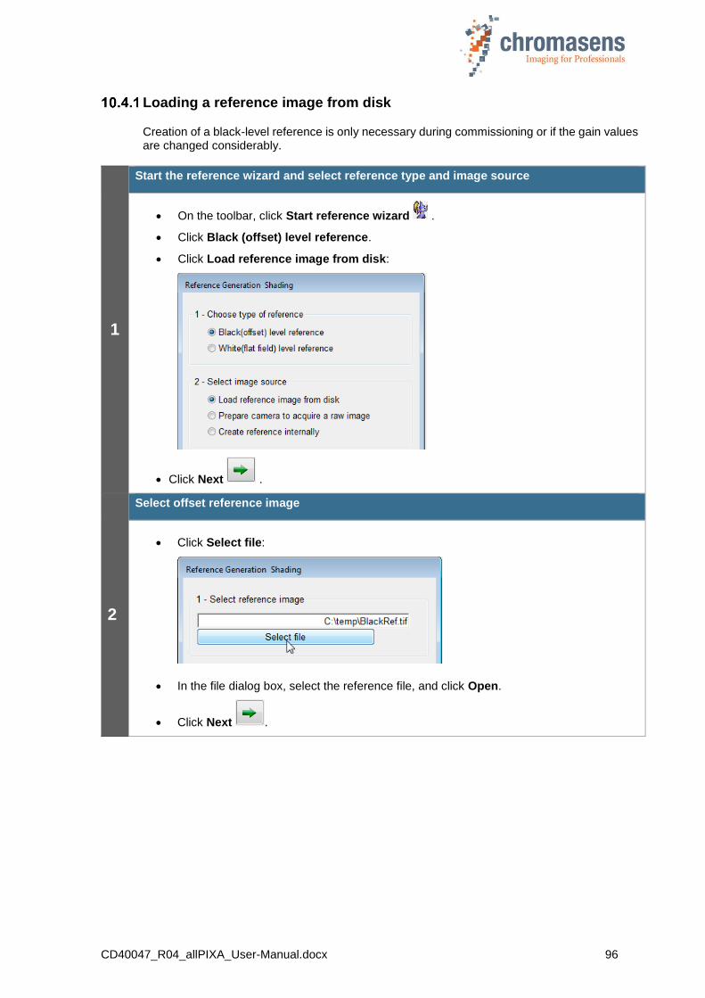
CD40047_R04_allPIXA_User-Manual.docx 96
Loading a reference image from disk
Creation of a black-level reference is only necessary during commissioning or if the gain values are changed considerably.
1
Start the reference wizard and select reference type and image source
On the toolbar, click Start reference wizard .
Click Black (offset) level reference.
Click Load reference image from disk:
Click Next .
2
Select offset reference image
Click Select file:
In the file dialog box, select the reference file, and click Open.
Click Next .
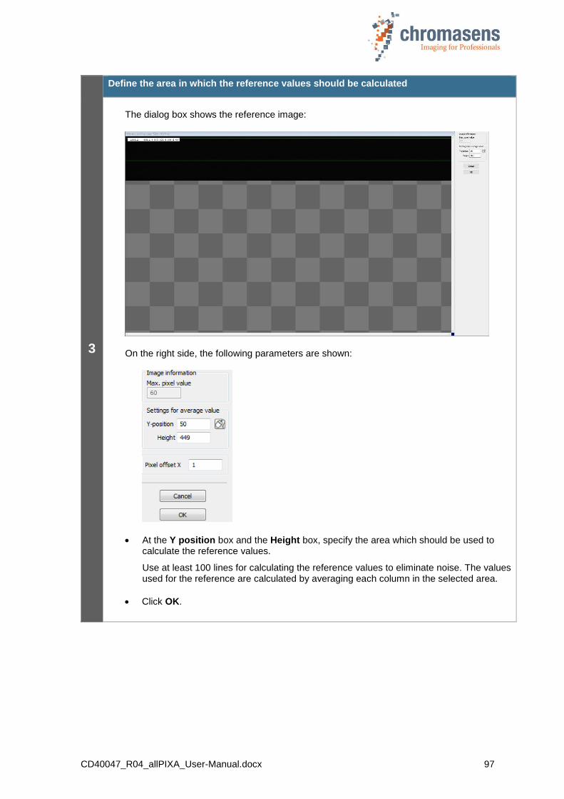
CD40047_R04_allPIXA_User-Manual.docx 97
3
Define the area in which the reference values should be calculated
The dialog box shows the reference image:
On the right side, the following parameters are shown:
At the Y position box and the Height box, specify the area which should be used to calculate the reference values.
Use at least 100 lines for calculating the reference values to eliminate noise. The values used for the reference are calculated by averaging each column in the selected area.
Click OK.

CD40047_R04_allPIXA_User-Manual.docx 98
4
Save reference data
In the No. of data set list, click the number of the data set in which the refrence data should be stored:
If the reference data should not be sent to the camera, clear the Send to camera check box.
To save the reference data to a file as backup, select the Save to disk check box, and then click Select file to specify folder and file name.
Click Next .
If the reference data are sent to the camera, a progress bar is shown, and the camera is reset afterward to make sure that the initial settings are again active. The last used setting is activated automatically.
Again click Next to close the wizard.
5
Activate black-level correction and check the result on the image.
On the toolbar, click Show settings , and then click Reference usage.
To check black-level correction, select the Activate black-level correction check box and check that the just updated data set is used:
At least a few pixels should have a value greater than 0 (for example 1 or 2) in the black image with activated black-level correction and covered lens. Otherwise, (if all pixels are 0) the image is over-compensated and you should repeat the steps for reference generation.
Click Transfer setting to camera to save the setting to volatile memory.
You may proceed to section 10.5 to generate a shading reference.

CD40047_R04_allPIXA_User-Manual.docx 99
Preparing the camera to acquire a raw reference
The creation of a black-level reference is only necessary during commissioning or if the gain values are changed considerably.
Make sure that all changes made to your current setting are saved permanently to the camera before using the Reference wizard. Otherwise, all changes get lost!
1
Get the camera to the desired working point
Place a white reference in front of the camera
Check lighting and focusing
Disable continuous white control
Save the parameters to the camera
2
Start the reference wizard and select reference type and image source
On the toolbar, click Start reference wizard .
Click Black (offset) level reference.
Click Prepare camera to acquire a raw image:
Click Next .
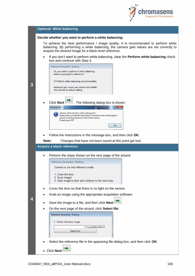
CD40047_R04_allPIXA_User-Manual.docx 100
3
Optional: White balancing
Decide whether you want to perform a white balancing:
To achieve the best performance / image quality, it is recommended to perform white balancing. By performing a white balancing, the camera gain values are set correctly to acquire the desired image for a black-level reference.
If you don’t want to perform white balancing, clear the Perform white balancing check box and continue with Step 4.
Click Next . The following dialog box is shown:
Follow the instructions in the message box, and then click OK.
Note: Changes that have not been saved at this point get lost.
4
Acquire a black reference:
Perform the steps shown on the next page of the wizard:
Cover the lens so that there is no light on the sensor.
Grab an image using the appropriate acquisition software.
Save the image to a file, and then click Next .
On the next page of the wizard, click Select file:
Select the reference file in the appearing file dialog box, and then click OK:
Click Next .
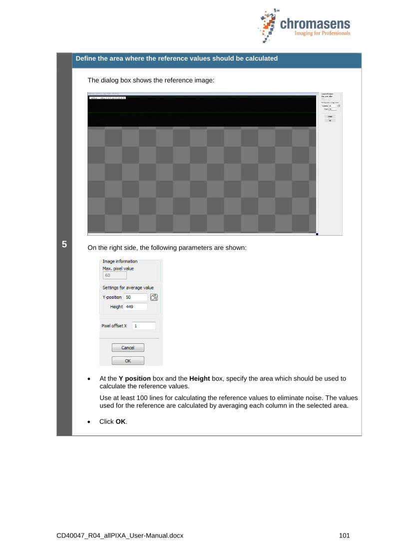
CD40047_R04_allPIXA_User-Manual.docx 101
5
Define the area where the reference values should be calculated
The dialog box shows the reference image:
On the right side, the following parameters are shown:
At the Y position box and the Height box, specify the area which should be used to calculate the reference values.
Use at least 100 lines for calculating the reference values to eliminate noise. The values used for the reference are calculated by averaging each column in the selected area.
Click OK.

CD40047_R04_allPIXA_User-Manual.docx 102
6
Saving reference data
In the No. of data set list, click the number of the data set in which the refrence data should be stored:
If the reference data should not be sent to the camera, clear the Send to camera check box.
To save the reference data to a file as backup, select the Save to disk check box, and then click Select file to specify folder and file name.
Click Next .
If the reference data are sent to the camera, a progress bar is shown, and the camera is reset afterward to make sure that the initial settings are again active. The last used setting is activated automatically.
Again click Next to close the wizard.
7
Activate black-level correction and check the result on the image.
On the toolbar, click Show settings , and then click Reference usage.
To check black-level correction, select the Activate black-level correction check box and check that the just updated data set is used:
At least a few pixels should have a value greater than 0 (for example 1 or 2) in the black image with activated black-level correction and covered lens. Otherwise, (if all pixels are 0) the image is over-compensated and you should repeat the steps for reference generation.
Click Transfer setting to camera to save the setting to volatile memory.
You may proceed to section 10.5Fehler! Verweisquelle konnte nicht gefunden erden. to generate a shading reference.
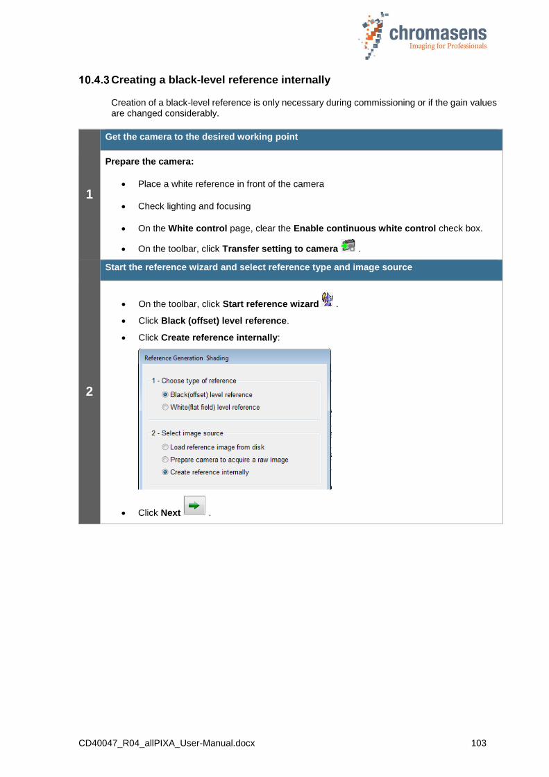
CD40047_R04_allPIXA_User-Manual.docx 103
Creating a black-level reference internally
Creation of a black-level reference is only necessary during commissioning or if the gain values are changed considerably.
1
Get the camera to the desired working point
Prepare the camera:
Place a white reference in front of the camera
Check lighting and focusing
On the White control page, clear the Enable continuous white control check box.
On the toolbar, click Transfer setting to camera .
2
Start the reference wizard and select reference type and image source
On the toolbar, click Start reference wizard .
Click Black (offset) level reference.
Click Create reference internally:
Click Next .

CD40047_R04_allPIXA_User-Manual.docx 104
3
Optional: White balancing
Decide whether you want to perform white balancing:
To achieve the best performance / image quality, it is recommended to perform white balancing. By performing a white balancing, the camera gain values are set correctly to acquire the desired image for a black-level reference.
If you don’t want to perform white balancing, clear the Perform white balancing check box and continue with Step 4.
Click Next . The following dialog box is shown:
Follow the instructions in the message box, and then click OK.
Note: Changes that have not been saved at this point get lost.
4
Start black-level correction:
In the Data set list, select the data set, in which the offset reference should be generated and stored:
In the Timeout value box, enter the timeout value in seconds.
Cover the lens so that the sensor is completely dark.
Click Next .
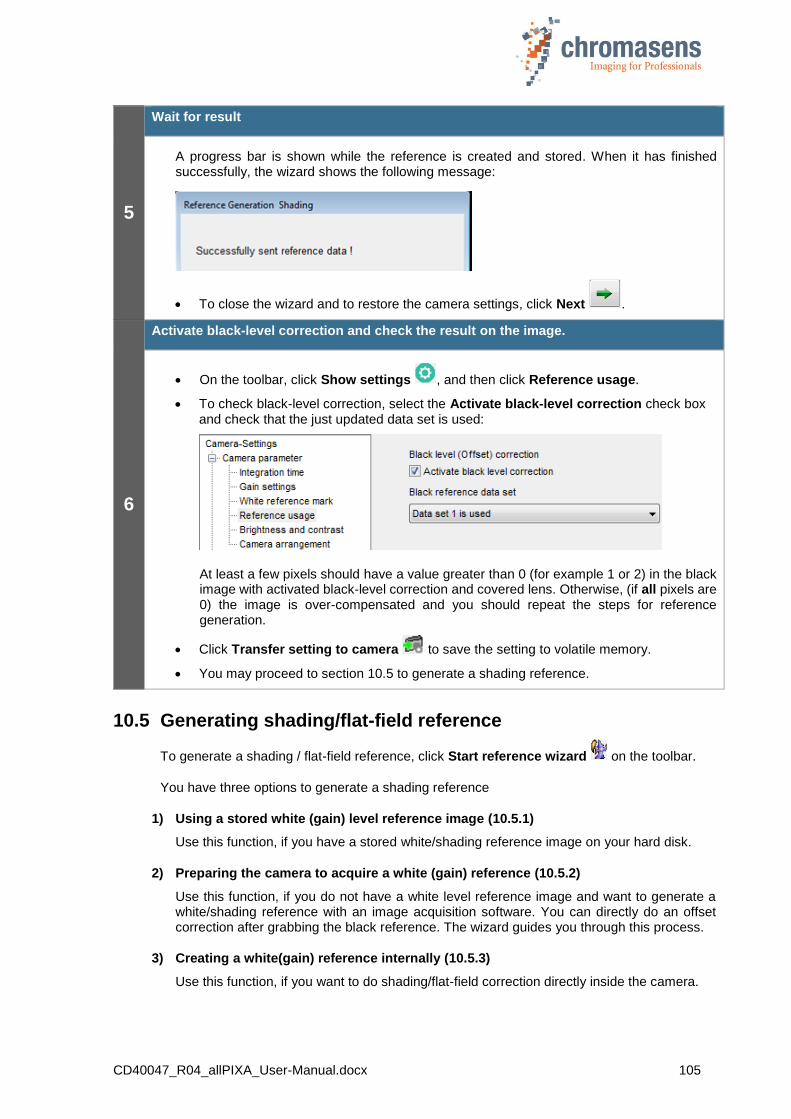
CD40047_R04_allPIXA_User-Manual.docx 105
5
Wait for result
A progress bar is shown while the reference is created and stored. When it has finished successfully, the wizard shows the following message:
To close the wizard and to restore the camera settings, click Next .
6
Activate black-level correction and check the result on the image.
On the toolbar, click Show settings , and then click Reference usage.
To check black-level correction, select the Activate black-level correction check box and check that the just updated data set is used:
At least a few pixels should have a value greater than 0 (for example 1 or 2) in the black image with activated black-level correction and covered lens. Otherwise, (if all pixels are 0) the image is over-compensated and you should repeat the steps for reference generation.
Click Transfer setting to camera to save the setting to volatile memory.
You may proceed to section 10.5 to generate a shading reference.
10.5 Generating shading/flat-field reference
To generate a shading / flat-field reference, click Start reference wizard on the toolbar.
You have three options to generate a shading reference
1) Using a stored white (gain) level reference image (10.5.1)
Use this function, if you have a stored white/shading reference image on your hard disk.
2) Preparing the camera to acquire a white (gain) reference (10.5.2)
Use this function, if you do not have a white level reference image and want to generate a white/shading reference with an image acquisition software. You can directly do an offset correction after grabbing the black reference. The wizard guides you through this process.
3) Creating a white(gain) reference internally (10.5.3)
Use this function, if you want to do shading/flat-field correction directly inside the camera.
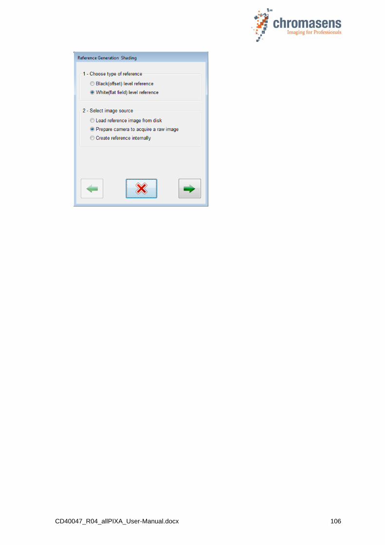
CD40047_R04_allPIXA_User-Manual.docx 106
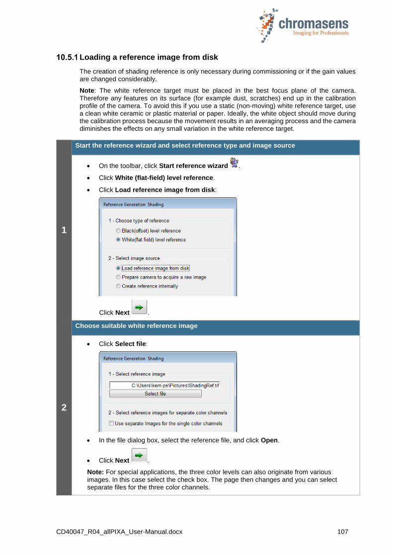
CD40047_R04_allPIXA_User-Manual.docx 107
Loading a reference image from disk
The creation of shading reference is only necessary during commissioning or if the gain values are changed considerably.
Note: The white reference target must be placed in the best focus plane of the camera. Therefore any features on its surface (for example dust, scratches) end up in the calibration profile of the camera. To avoid this if you use a static (non-moving) white reference target, use a clean white ceramic or plastic material or paper. Ideally, the white object should move during the calibration process because the movement results in an averaging process and the camera diminishes the effects on any small variation in the white reference target.
1
Start the reference wizard and select reference type and image source
On the toolbar, click Start reference wizard .
Click White (flat-field) level reference.
Click Load reference image from disk:
Click Next .
2
Choose suitable white reference image
Click Select file:
In the file dialog box, select the reference file, and click Open.
Click Next .
Note: For special applications, the three color levels can also originate from various images. In this case select the check box. The page then changes and you can select separate files for the three color channels.
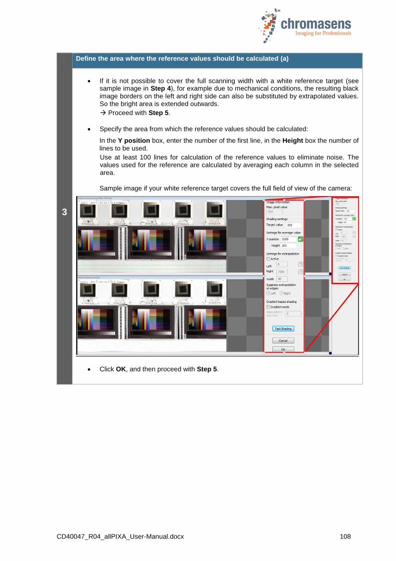
CD40047_R04_allPIXA_User-Manual.docx 108
3
Define the area where the reference values should be calculated (a)
If it is not possible to cover the full scanning width with a white reference target (see sample image in Step 4), for example due to mechanical conditions, the resulting black image borders on the left and right side can also be substituted by extrapolated values. So the bright area is extended outwards.
Proceed with Step 5.
Specify the area from which the reference values should be calculated:
In the Y position box, enter the number of the first line, in the Height box the number of lines to be used.
Use at least 100 lines for calculation of the reference values to eliminate noise. The values used for the reference are calculated by averaging each column in the selected area.
Sample image if your white reference target covers the full field of view of the camera:
Click OK, and then proceed with Step 5.
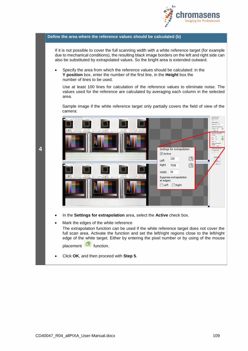
CD40047_R04_allPIXA_User-Manual.docx 109
4
Define the area where the reference values should be calculated (b)
If it is not possible to cover the full scanning width with a white reference target (for example due to mechanical conditions), the resulting black image borders on the left and right side can also be substituted by extrapolated values. So the bright area is extended outward.
Specify the area from which the reference values should be calculated: in the Y position box, enter the number of the first line, in the Height box the number of lines to be used.
Use at least 100 lines for calculation of the reference values to eliminate noise. The values used for the reference are calculated by averaging each column in the selected area.
Sample image if the white reference target only partially covers the field of view of the camera:
In the Settings for extrapolation area, select the Active check box.
Mark the edges of the white reference
The extrapolation function can be used if the white reference target does not cover the full scan area. Activate the function and set the left/right regions close to the left/right edge of the white target. Either by entering the pixel number or by using of the mouse
placement function.
Click OK, and then proceed with Step 5.
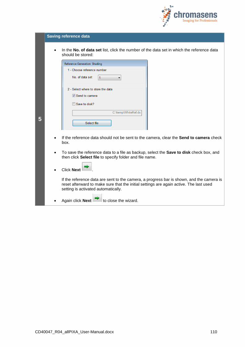
CD40047_R04_allPIXA_User-Manual.docx 110
5
Saving reference data
In the No. of data set list, click the number of the data set in which the reference data should be stored:
If the reference data should not be sent to the camera, clear the Send to camera check box.
To save the reference data to a file as backup, select the Save to disk check box, and then click Select file to specify folder and file name.
Click Next .
If the reference data are sent to the camera, a progress bar is shown, and the camera is reset afterward to make sure that the initial settings are again active. The last used setting is activated automatically.
Again click Next to close the wizard.
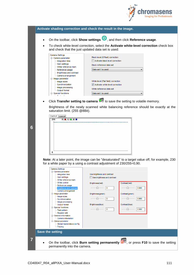
CD40047_R04_allPIXA_User-Manual.docx 111
6
Activate shading correction and check the result in the image.
On the toolbar, click Show settings , and then click Reference usage.
To check white-level correction, select the Activate white-level correction check box and check that the just updated data set is used:
Click Transfer setting to camera to save the setting to volatile memory.
Brightness of the newly scanned white balancing reference should be exactly at the saturation limit. (255 @8Bit).
Note: At a later point, the image can be "desaturated" to a target value off, for example, 230 for a white paper by a using a contrast adjustment of 230/255=0,90.
7
Save the setting
On the toolbar, click Burn setting permanently , or press F10 to save the setting permanently into the camera.

CD40047_R04_allPIXA_User-Manual.docx 112
Preparing the camera to acquire raw image
The creation of shading reference is only necessary during commissioning or if the gain values are changed considerably.
Make sure that all changes made to your current setting are saved permanently to the camera before you use the Reference wizard. Otherwise, all changes get lost!
1
Get the camera to the desired working point
Place a white reference in front of the camera
Check the lighting and focusing
Disable continuous white control
Save the parameters to the camera
Optional: Activate black-level correction
Optional: Perform a white balancing
Note: The white reference target has to be placed in the best focus plane of the camera. Therefore any features on its surface (for example dust, scratches) end up in the calibration profile of the camera. To avoid this if you use a static (non-moving) white reference target, use a clean white ceramic or plastic material, not paper. Ideally, the white object should move during the calibration process because the movement results in an averaging process and the camera diminishes the effects on any small variation in the white reference.
2
Start the reference wizard and select reference type and image source
On the toolbar, click Start reference wizard .
Click White (flat-field) level reference.
Click Prepare camera to acquire a raw image:
Click Next .

CD40047_R04_allPIXA_User-Manual.docx 113
3
Optional: White balancing
Decide whether you want to perform a white balancing:
To achieve the best performance / image quality, it is recommended to perform white balancing. By performing a white balancing, the camera gain values are set correctly to acquire the desired image for a black-level reference.
If you don’t want to perform white balancing, clear the Perform white balancing check box and continue with Step 4.
Click Next . The following dialog box is shown:
Follow the instructions in the message box, and then click OK.
Note: Changes that have not been saved at this point get lost.
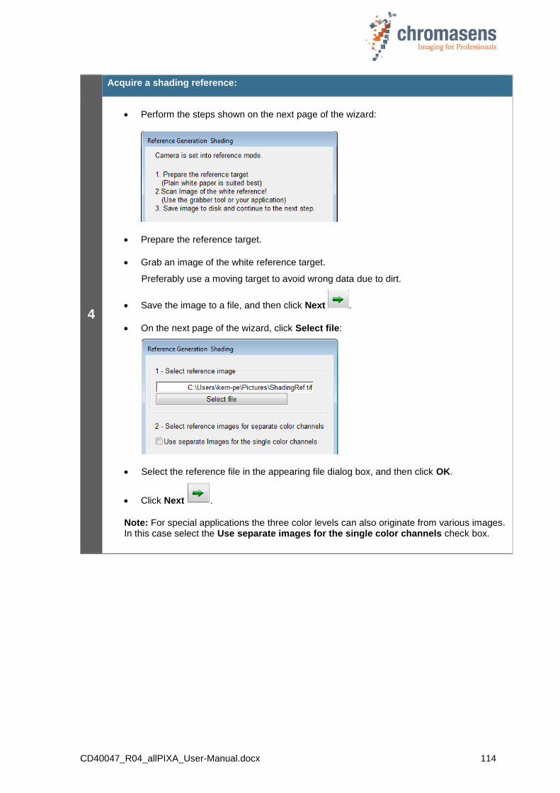
CD40047_R04_allPIXA_User-Manual.docx 114
4
Acquire a shading reference:
Perform the steps shown on the next page of the wizard:
Prepare the reference target.
Grab an image of the white reference target.
Preferably use a moving target to avoid wrong data due to dirt.
Save the image to a file, and then click Next .
On the next page of the wizard, click Select file:
Select the reference file in the appearing file dialog box, and then click OK.
Click Next .
Note: For special applications the three color levels can also originate from various images. In this case select the Use separate images for the single color channels check box.

CD40047_R04_allPIXA_User-Manual.docx 115
5
Define the area where the reference values should be calculated (a)
If it is not possible to cover the full scanning width with a white reference target (for example due to mechanical conditions), the resulting black image borders on the left and right side can also be substituted by extrapolated values. So the bright area is extended outwards.
Proceed with Step 7.
Specify the area from which the reference values should be calculated: in the Y position box, enter the number of the first line, in the Height box the number of lines to be used.
Use at least 100 lines for calculating the reference values to eliminate noise. The values used for the reference are calculated by averaging each column in the selected area.
Click OK, and then proceed with Step 7.
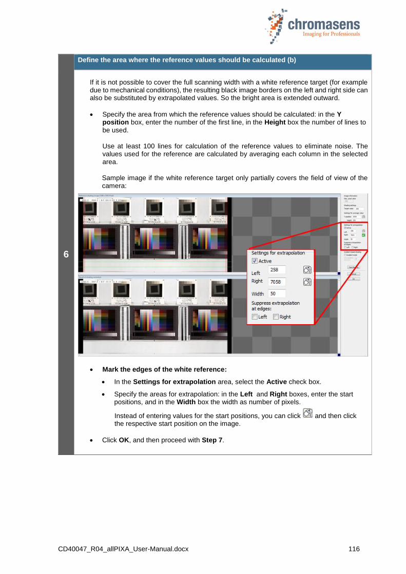
CD40047_R04_allPIXA_User-Manual.docx 116
6
Define the area where the reference values should be calculated (b)
If it is not possible to cover the full scanning width with a white reference target (for example due to mechanical conditions), the resulting black image borders on the left and right side can also be substituted by extrapolated values. So the bright area is extended outward.
Specify the area from which the reference values should be calculated: in the Y position box, enter the number of the first line, in the Height box the number of lines to be used.
Use at least 100 lines for calculation of the reference values to eliminate noise. The values used for the reference are calculated by averaging each column in the selected area.
Sample image if the white reference target only partially covers the field of view of the camera:
Mark the edges of the white reference:
In the Settings for extrapolation area, select the Active check box.
Specify the areas for extrapolation: in the Left and Right boxes, enter the start positions, and in the Width box the width as number of pixels.
Instead of entering values for the start positions, you can click and then click the respective start position on the image.
Click OK, and then proceed with Step 7.

CD40047_R04_allPIXA_User-Manual.docx 117
7
Saving reference data
In the No. of data set list, click the number of the data set in which the reference data should be stored:
If the reference data should not be sent to the camera, clear the Send to camera check box.
To save the reference data to a file as backup, select the Save to disk check box, and then click Select file to specify folder and file name.
Click Next .
If the reference data are sent to the camera, a progress bar is shown, and the camera is reset afterward to make sure that the initial settings are again active. The last used setting is activated automatically.
Again click Next to close the wizard.

CD40047_R04_allPIXA_User-Manual.docx 118
8
Activate shading correction and check the result on the image.
On the toolbar, click Show settings , and then click Reference usage.
To check white-level correction, select the Activate white-level correction check box and check that the just updated data set is used:
Click Transfer setting to camera to save the setting to volatile memory.
Brightness of the newly scanned white balancing reference should be exactly at the saturation limit. (255 @8Bit).
Note: At a later point, the image can be "desaturated" to a target value off, for example, 230 for a white paper by using a contrast adjustment of 230/255=0,90.
9
Save the setting
On the toolbar, click Burn setting permanently , or press F10 to save the setting permanently into the camera.
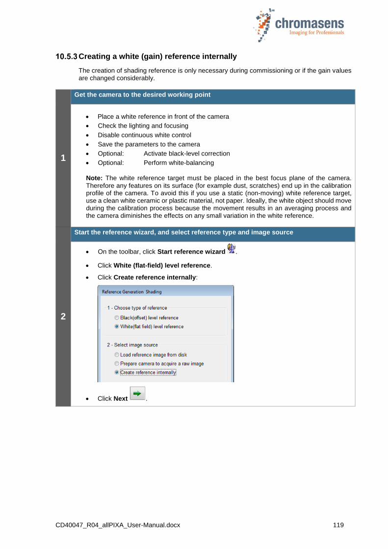
CD40047_R04_allPIXA_User-Manual.docx 119
Creating a white (gain) reference internally
The creation of shading reference is only necessary during commissioning or if the gain values are changed considerably.
1
Get the camera to the desired working point
Place a white reference in front of the camera
Check the lighting and focusing
Disable continuous white control
Save the parameters to the camera
Optional: Activate black-level correction
Optional: Perform white-balancing
Note: The white reference target must be placed in the best focus plane of the camera. Therefore any features on its surface (for example dust, scratches) end up in the calibration profile of the camera. To avoid this if you use a static (non-moving) white reference target, use a clean white ceramic or plastic material, not paper. Ideally, the white object should move during the calibration process because the movement results in an averaging process and the camera diminishes the effects on any small variation in the white reference.
2
Start the reference wizard, and select reference type and image source
On the toolbar, click Start reference wizard .
Click White (flat-field) level reference.
Click Create reference internally:
Click Next .

CD40047_R04_allPIXA_User-Manual.docx 120
3
Optional: White balancing
Decide whether you want to perform a white balancing:
To achieve the best performance / image quality, it is recommended to perform white balancing. By performing a white balancing, the camera gain values are set correctly to acquire the desired image for a black-level reference.
If you don’t want to perform white balancing, clear the Perform white balancing check box and continue with Step 5.
Click Next . The following dialog box is shown:
Follow the instructions in the message box, and then click OK.
Note: Changes that have not been saved at this point get lost.
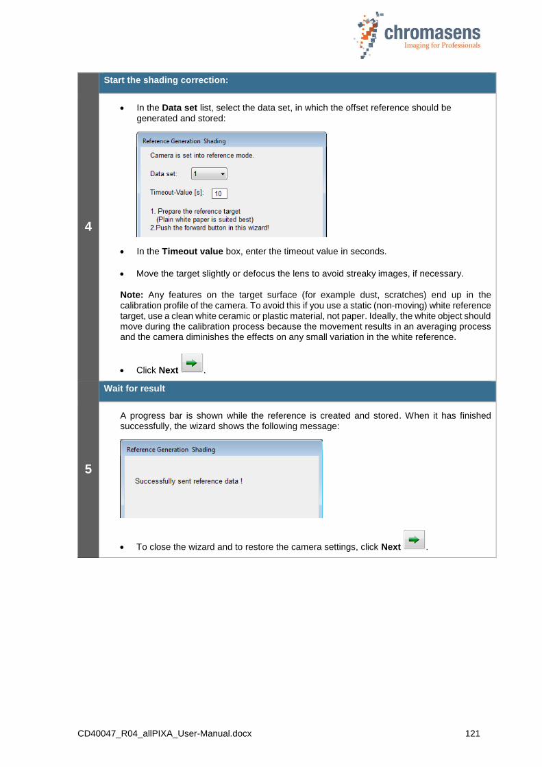
CD40047_R04_allPIXA_User-Manual.docx 121
4
Start the shading correction:
In the Data set list, select the data set, in which the offset reference should be generated and stored:
In the Timeout value box, enter the timeout value in seconds.
Move the target slightly or defocus the lens to avoid streaky images, if necessary.
Note: Any features on the target surface (for example dust, scratches) end up in the calibration profile of the camera. To avoid this if you use a static (non-moving) white reference target, use a clean white ceramic or plastic material, not paper. Ideally, the white object should move during the calibration process because the movement results in an averaging process and the camera diminishes the effects on any small variation in the white reference.
Click Next .
5
Wait for result
A progress bar is shown while the reference is created and stored. When it has finished successfully, the wizard shows the following message:
To close the wizard and to restore the camera settings, click Next .
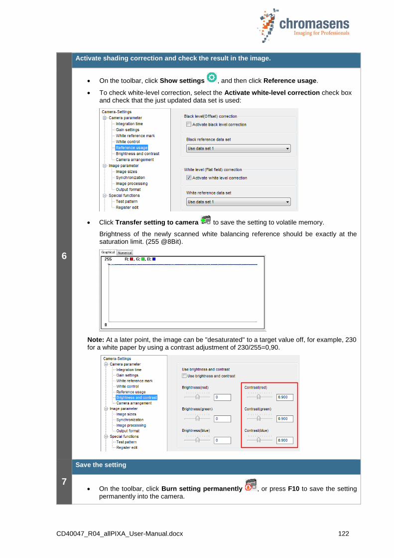
CD40047_R04_allPIXA_User-Manual.docx 122
6
Activate shading correction and check the result in the image.
On the toolbar, click Show settings , and then click Reference usage.
To check white-level correction, select the Activate white-level correction check box and check that the just updated data set is used:
Click Transfer setting to camera to save the setting to volatile memory.
Brightness of the newly scanned white balancing reference should be exactly at the saturation limit. (255 @8Bit).
Note: At a later point, the image can be "desaturated" to a target value off, for example, 230 for a white paper by using a contrast adjustment of 230/255=0,90.
7
Save the setting
On the toolbar, click Burn setting permanently , or press F10 to save the setting permanently into the camera.
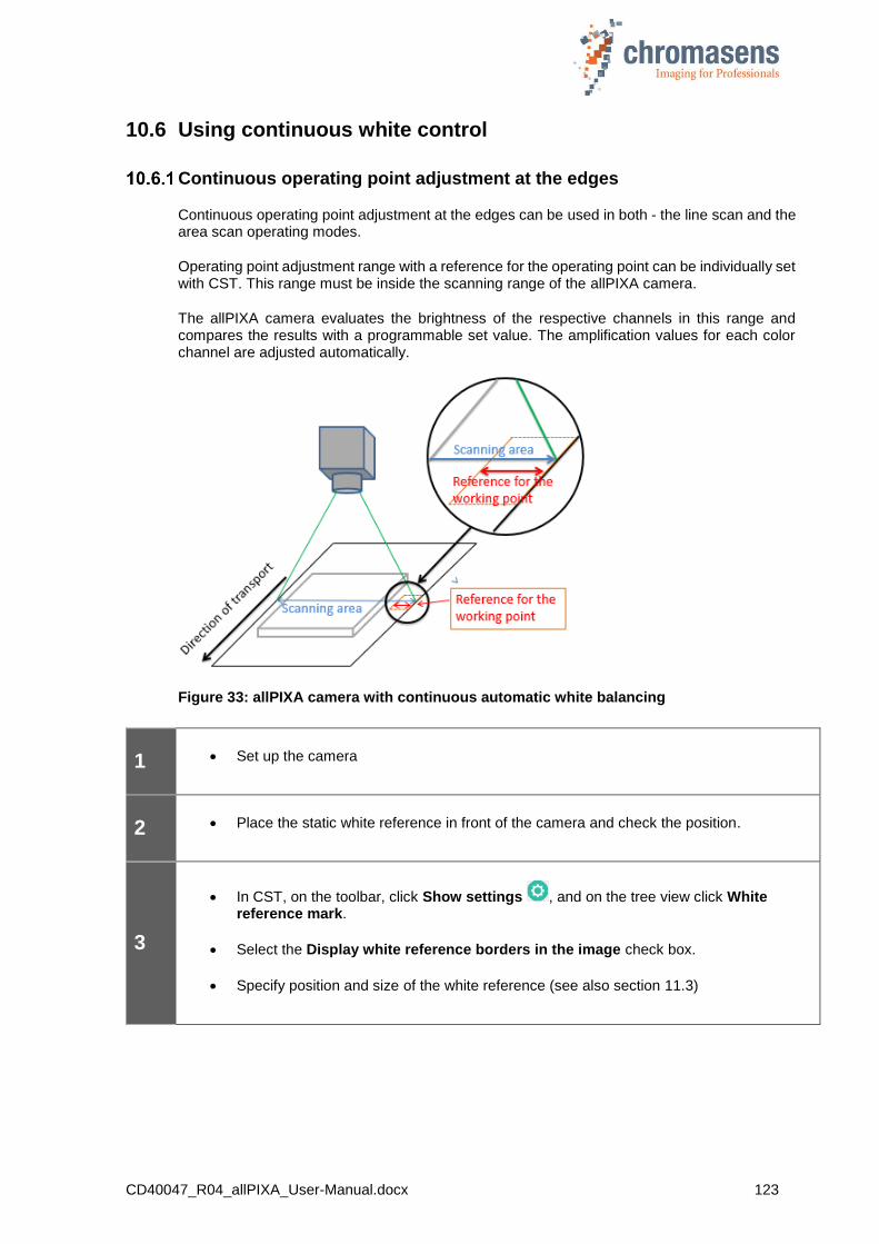
CD40047_R04_allPIXA_User-Manual.docx 123
10.6 Using continuous white control
Continuous operating point adjustment at the edges
Continuous operating point adjustment at the edges can be used in both - the line scan and the area scan operating modes.
Operating point adjustment range with a reference for the operating point can be individually set with CST. This range must be inside the scanning range of the allPIXA camera.
The allPIXA camera evaluates the brightness of the respective channels in this range and compares the results with a programmable set value. The amplification values for each color channel are adjusted automatically.
Figure 33: allPIXA camera with continuous automatic white balancing
1 Set up the camera
2 Place the static white reference in front of the camera and check the position.
3
In CST, on the toolbar, click Show settings , and on the tree view click White reference mark.
Select the Display white reference borders in the image check box.
Specify position and size of the white reference (see also section 11.3)
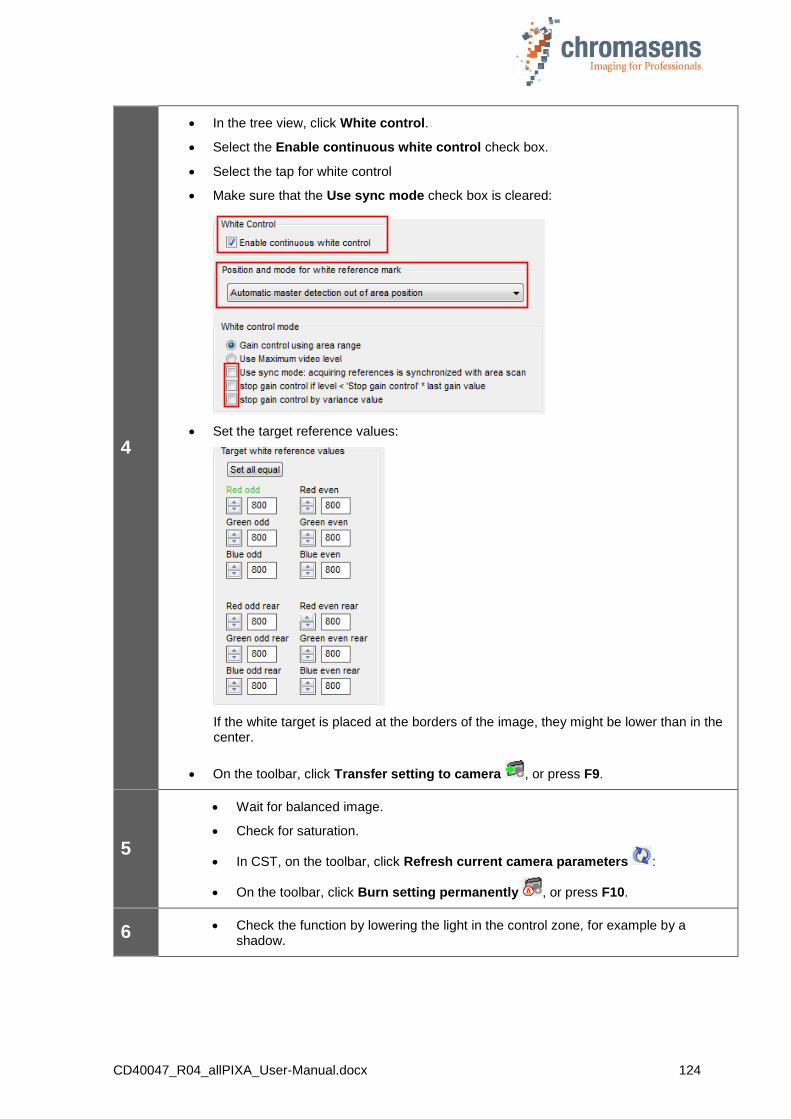
CD40047_R04_allPIXA_User-Manual.docx 124
4
In the tree view, click White control.
Select the Enable continuous white control check box.
Select the tap for white control
Make sure that the Use sync mode check box is cleared:
Set the target reference values:
If the white target is placed at the borders of the image, they might be lower than in the center.
On the toolbar, click Transfer setting to camera , or press F9.
5
Wait for balanced image.
Check for saturation.
In CST, on the toolbar, click Refresh current camera parameters :
On the toolbar, click Burn setting permanently , or press F10.
6 Check the function by lowering the light in the control zone, for example by a shadow.

CD40047_R04_allPIXA_User-Manual.docx 125
Image-synchronous operating point adjustment on the object (ROI)
The image-synchronous operating point adjustment can only be used in area scan operating mode.
If the object has an area which is suitable as reference for the operating point, this area can be set in the allPIXA camera as an ROI (Region of Interest). The allPIXA camera evaluates the brightness of the respective channels in this range and compares the results with a programmable set value. The amplification values for each color channel are adjusted automatically.
Figure 34: Image-synchronous operating point adjustment on the object (ROI)
NOTE I This mode requires an image trigger signal at the allPIXA camera. The image trigger can be provided by CC1 through the CameraLink or by the IO port of it. The allPIXA camera has to be operated in frame scan mode. Gain control has to be set to image synchronized mode.
NOTE II At image-synchronized mode, the behavior of the closed loop control is slower than in free-running mode.
1 Set up the camera.
2 Start the transport with sample objects.
3
In CST, on the toolbar, click Show settings , and on the tree view click White reference mark.
Select the Display white reference borders in the image check box.
Specify position and size of the white reference area (see also section 11.3).

CD40047_R04_allPIXA_User-Manual.docx 126
4
In the tree view, click White control.
Select the Enable continuous white control check box.
Select the tap for white control
Select the Use sync mode check box:
Set the target reference values:
If the white target is placed at the borders of the image, they might be lower than in the center.
On the toolbar, click Transfer setting to camera , or press F9.
5
Wait for balanced image.
Check for saturation.
In CST, on the toolbar, click Refresh current camera parameters :
Set the initial gaining values.
On the toolbar, click Burn setting permanently , or press F10.
6 Check the function by lowering the light in the control zone, for example by a shadow.

CD40047_R04_allPIXA_User-Manual.docx 127
10.7 Updating the firmware of the allPIXA camera
Never disconnect the power or the connection to the camera during the update procedure.
Perform the following steps to update the camera safely.
Download the current firmware from the Chromasens website (https://www.chromasens.de/en/user).
You either must have a valid partner account to access the software or follow the link provided by the shipment of the camera.
If you are not already registered, request an account. It is free of charge!
Be sure to enter valid information into the request form. Otherwise, you are not granted access to the site.
Be assured that your information is not passed on to others outside Chromasens.
The software can be found in the login section of the Chromasens homepage or directly by following the link that was delivered with your allPIXA wave-camera:
The Software can be found on the Chromasens homepage or directly by following the link that was delivered with your allPIXA-camera:

CD40047_R04_allPIXA_User-Manual.docx 128
1
Start CST and select the correct port to connect with the camera.
Click Show system configuration to show the System configuration view.
Backup your settings Some internal settings may be reset to factory defaults when you perform a firmware update. Therefore, it is recommended to save your own settings as backup.
o Click Save multiple settings to disk , select a folder in the Upload Settings
dialog box and then click Save settings .
Settings are saved as single files in the specified folder. The setting number is appended to the specified filename. (example: setting 17 is saved as backup_121207_17.mk)
c b
a
b
c
a
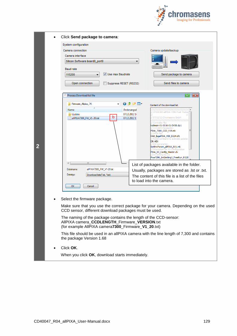
CD40047_R04_allPIXA_User-Manual.docx 129
2
Click Send package to camera:
Select the firmware package.
Make sure that you use the correct package for your camera. Depending on the used CCD sensor, different download packages must be used.
The naming of the package contains the length of the CCD-sensor: AllPIXA camera_CCDLENGTH_Firmware_VERSION.txt (for example AllPIXA camera7300_Firmware_V1_20.txt)
This file should be used in an allPIXA camera with the line length of 7,300 and contains the package Version 1.68
Click OK.
When you click OK, download starts immediately.
List of packages available in the folder.
Usually, packages are stored as .lst or .txt.
The content of this file is a list of the files to load into the camera.
b
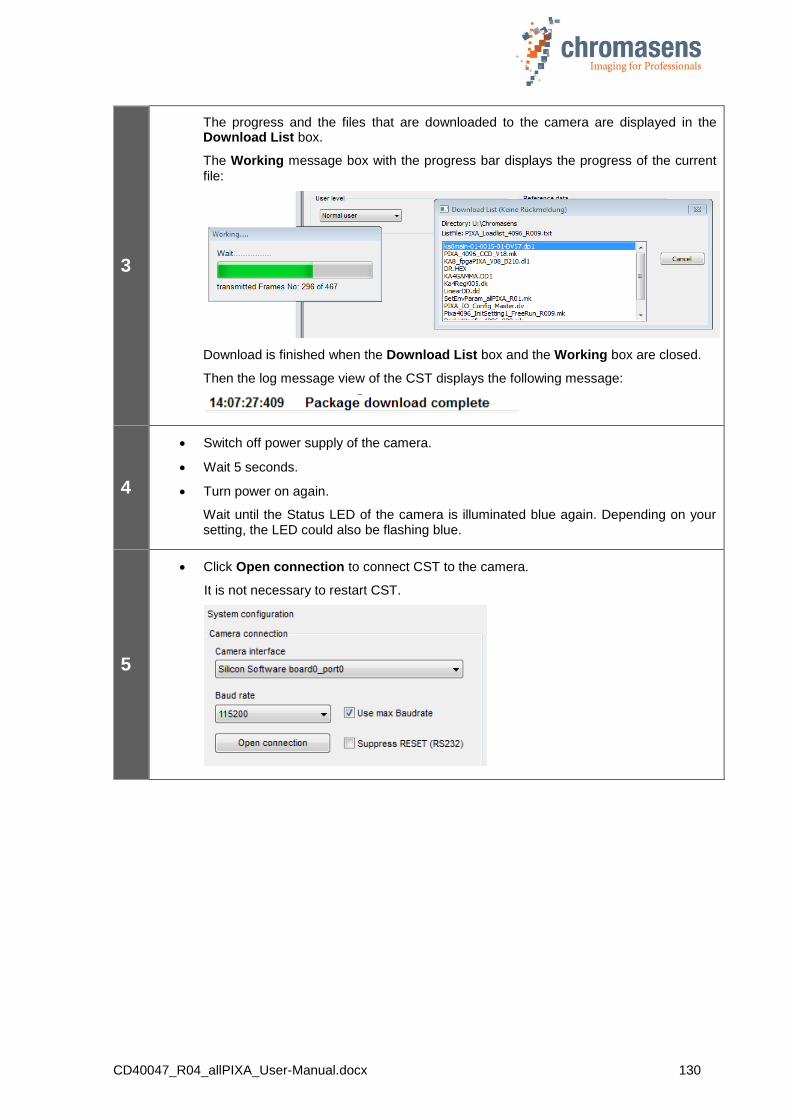
CD40047_R04_allPIXA_User-Manual.docx 130
3
The progress and the files that are downloaded to the camera are displayed in the Download List box.
The Working message box with the progress bar displays the progress of the current file:
Download is finished when the Download List box and the Working box are closed.
Then the log message view of the CST displays the following message:
4
Switch off power supply of the camera.
Wait 5 seconds.
Turn power on again.
Wait until the Status LED of the camera is illuminated blue again. Depending on your setting, the LED could also be flashing blue.
5
Click Open connection to connect CST to the camera.
It is not necessary to restart CST.
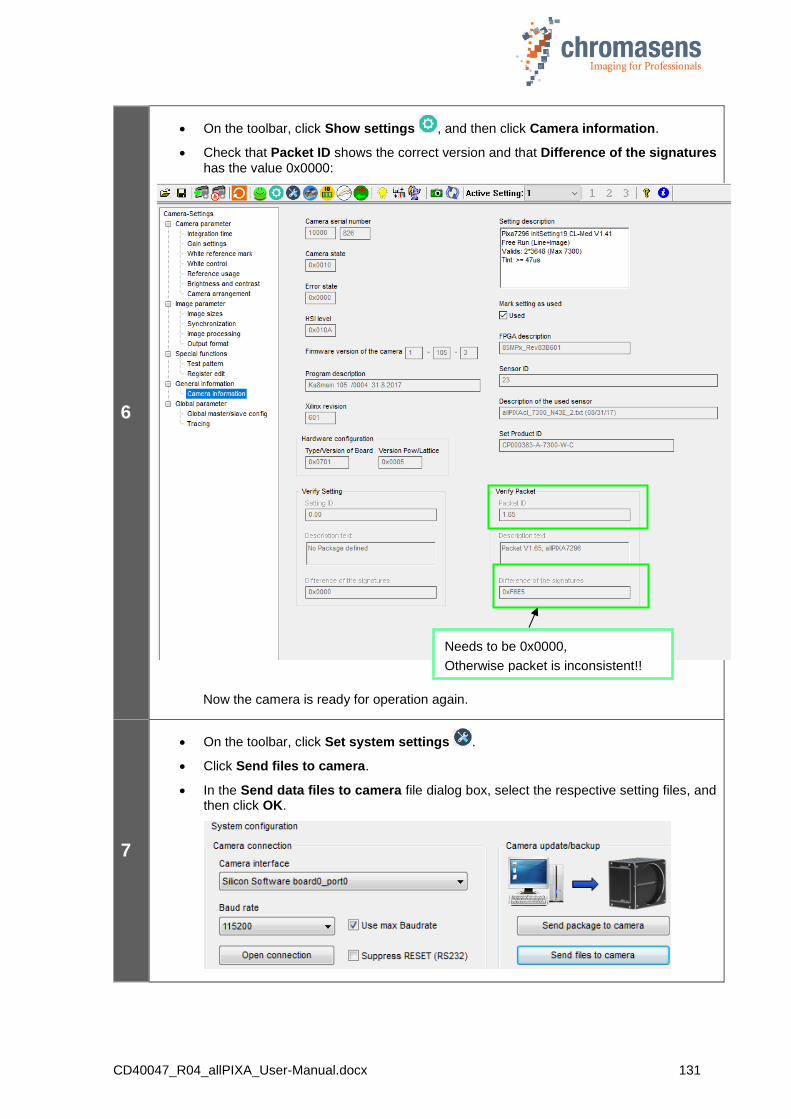
CD40047_R04_allPIXA_User-Manual.docx 131
6
On the toolbar, click Show settings , and then click Camera information.
Check that Packet ID shows the correct version and that Difference of the signatures has the value 0x0000:
Now the camera is ready for operation again.
7
On the toolbar, click Set system settings .
Click Send files to camera.
In the Send data files to camera file dialog box, select the respective setting files, and then click OK.
Needs to be 0x0000,
Otherwise packet is inconsistent!!
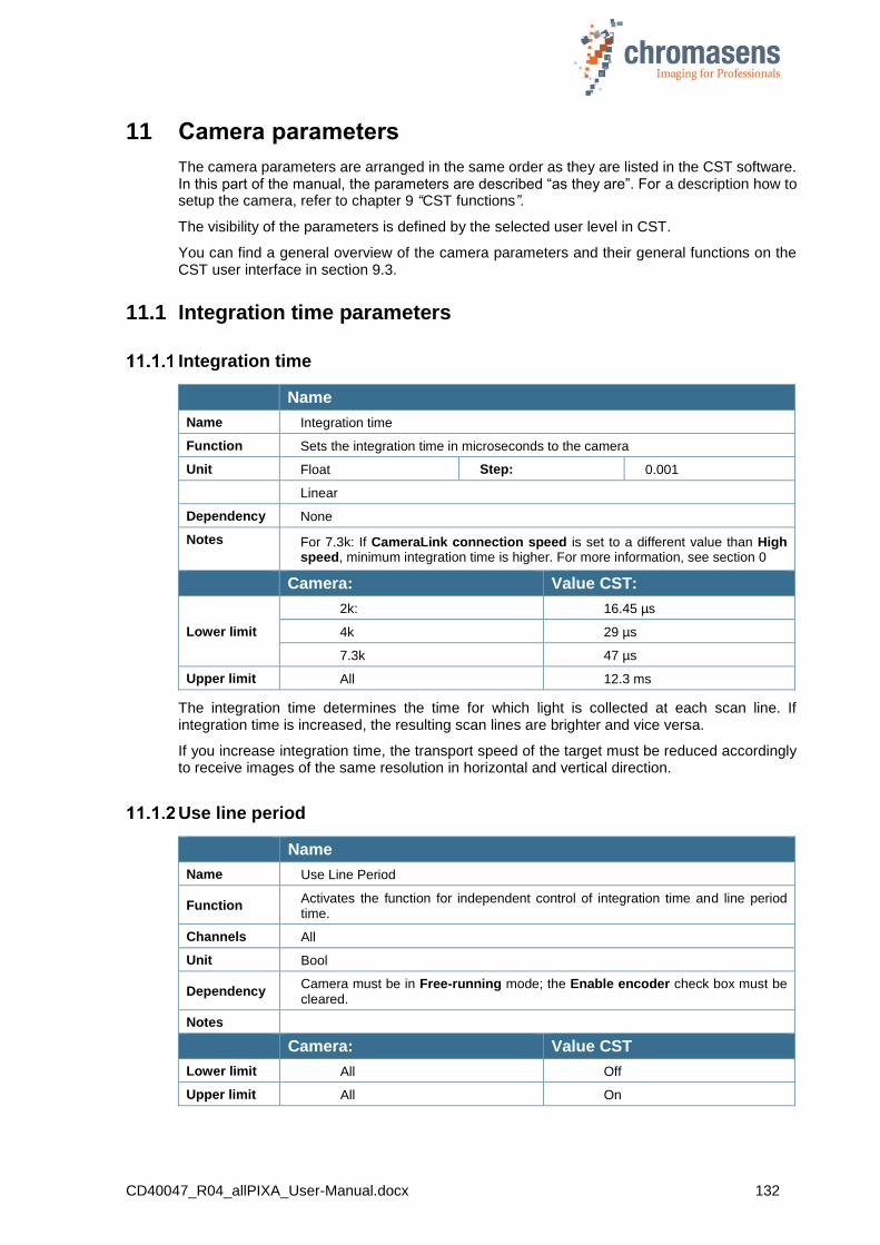
CD40047_R04_allPIXA_User-Manual.docx 132
11 Camera parameters
The camera parameters are arranged in the same order as they are listed in the CST software. In this part of the manual, the parameters are described “as they are”. For a description how to setup the camera, refer to chapter 9 “CST functions”.
The visibility of the parameters is defined by the selected user level in CST.
You can find a general overview of the camera parameters and their general functions on the CST user interface in section 9.3.
11.1 Integration time parameters
Integration time
Name
Name Integration time
Function Sets the integration time in microseconds to the camera
Unit Float Step: 0.001
Linear
Dependency None
Notes
For 7.3k: If CameraLink connection speed is set to a different value than High speed, minimum integration time is higher. For more information, see section 0
Camera: Value CST:
Lower limit
2k: 16.45 µs
4k 29 µs
7.3k 47 µs
Upper limit All 12.3 ms
The integration time determines the time for which light is collected at each scan line. If integration time is increased, the resulting scan lines are brighter and vice versa.
If you increase integration time, the transport speed of the target must be reduced accordingly to receive images of the same resolution in horizontal and vertical direction.
Use line period
Name
Name Use Line Period
Function Activates the function for independent control of integration time and line period time.
Channels All
Unit Bool
Dependency Camera must be in Free-running mode; the Enable encoder check box must be cleared.
Notes
Camera: Value CST
Lower limit All Off
Upper limit All On
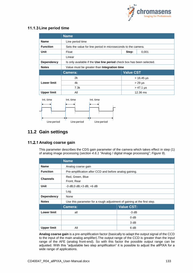
CD40047_R04_allPIXA_User-Manual.docx 133
Line period time
Name
Name Line period time
Function Sets the value for line period in microseconds to the camera.
Unit Float Step: 0,001
Linear
Dependency Is only available if the Use line period check box has been selected.
Notes Value must be greater than Integration time
Camera: Value CST
Lower limit
2k > 16.45 µs
4k > 29 µs
7.3k > 47.1 µs
Upper limit All 12.36 ms
11.2 Gain settings
Analog coarse gain
This parameter describes the CDS gain parameter of the camera which takes effect in step (1) of analog image processing (section 4.6.1 “Analog / digital image processing”; Figure 9).
Name
Name Analog coarse gain
Function Pre-amplification after CCD and before analog gaining.
Channels Red, Green, Blue
Front; Rear
Unit -3 dB;0 dB;+3 dB; +6 dB
Log.
Dependency None
Notes Use this parameter for a rough adjustment of gaining at the first step.
Camera: Value CST:
Lower limit all -3 dB
0 dB
3 dB
Upper limit All 6 dB
Analog coarse gain is a pre-amplification factor (basically to adapt the output signal of the CCD to the input of the main analog amplifier).The output range of the CCD is greater than the input range of the AFE (analog front-end). So with this factor the possible output range can be adjusted. With this “adjustable two step amplification” it is possible to adjust the allPIXA for a wide range of applications.
Line period Line period Line period
Int. time Int. time Int. time

CD40047_R04_allPIXA_User-Manual.docx 134
Usage: If the current gaining values are higher than about 200, the Analog coarse gain amplifier may be used (set to a higher amplification factor) to decrease gain values. Otherwise, the image pixel noise increases.
It is recommended to operate the camera with current gaining values in a range from 80 – 200 for best image quality by using the Analog coarse gain function to pre-adjust the actual gain range
Note: If the output signal of the CCD is higher than the possible input signal of the AFE, this might cause “saturation” in the image lower than 255. Therefore analog coarse gain has to be set to – 3 dB.
Current camera gain values
This parameter describes the analog gaining parameter of the camera which takes effect in step (2) of analog image processing (section 4.6.1, “Figure 9: Analog process of the allPIXA camera (block diagram)”).
With active white control, this parameter refers to the gain values labeled with (3) in the diagram of section 4.10.
Name
Name Current camera gain values
Function Gaining values for the analog gaining of the camera.
Channels Red, Green, Blue;Odd; Even; Front; Rear
Unit Integer
Log.
Dependency None
Notes
One step of this parameter refers to 0.0359 dB,
27.85 steps refer to 1 dB.
By increasing up to 168 steps, it doubles the signal.
Camera: Value:
Lower limit all 0
Upper limit all 700
Camera startup gain values
Name
Name Camera start gain values
Function In accordance with these values, the gaining values are updated at startup of the camera or if a setting is loaded for faster startup behavior of the closed-loop control for white balancing.
Channels Red, Green, Blue; Odd; Even; Front; Rear
Unit Integer
Linear
Dependency None
Notes
Camera: Value:
Lower limit All 0
Upper limit All 700
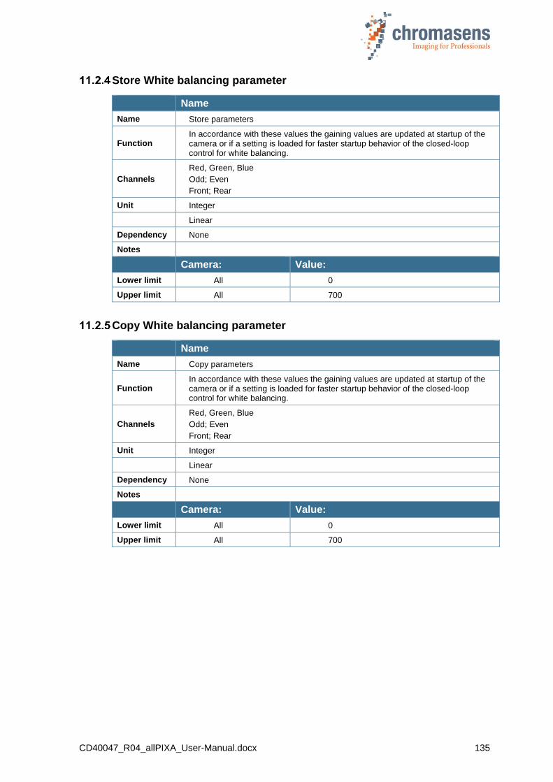
CD40047_R04_allPIXA_User-Manual.docx 135
Store White balancing parameter
Name
Name Store parameters
Function In accordance with these values the gaining values are updated at startup of the camera or if a setting is loaded for faster startup behavior of the closed-loop control for white balancing.
Channels
Red, Green, Blue
Odd; Even
Front; Rear
Unit Integer
Linear
Dependency None
Notes
Camera: Value:
Lower limit All 0
Upper limit All 700
Copy White balancing parameter
Name
Name Copy parameters
Function In accordance with these values the gaining values are updated at startup of the camera or if a setting is loaded for faster startup behavior of the closed-loop control for white balancing.
Channels
Red, Green, Blue
Odd; Even
Front; Rear
Unit Integer
Linear
Dependency None
Notes
Camera: Value:
Lower limit All 0
Upper limit All 700
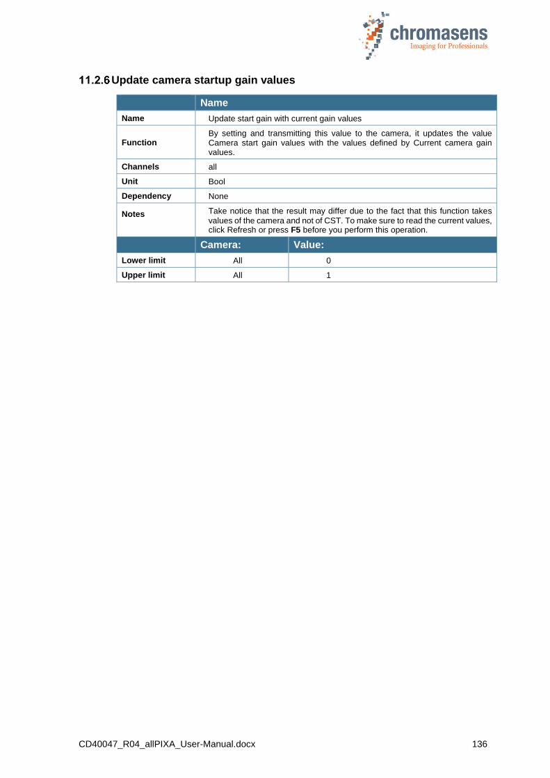
CD40047_R04_allPIXA_User-Manual.docx 136
Update camera startup gain values
Name
Name Update start gain with current gain values
Function By setting and transmitting this value to the camera, it updates the value Camera start gain values with the values defined by Current camera gain values.
Channels all
Unit Bool
Dependency None
Notes
Take notice that the result may differ due to the fact that this function takes values of the camera and not of CST. To make sure to read the current values, click Refresh or press F5 before you perform this operation.
Camera: Value:
Lower limit All 0
Upper limit All 1

CD40047_R04_allPIXA_User-Manual.docx 137
11.3 White reference mark
Position and size in CCD direction
NOTE Attention: The white reference area may not overstep the tap border.
For the position in CCD direction of the white reference control zone you may have two possibilities:
“Relative” x position:
The x position of the white reference mark can be defined “relative” to the current image window. If defined relative, the reference position moves with changing the scan line length of the current scan window.
“Absolute” x position
The x position of the white reference mark can be defined “absolute” within the maximum scan window. If defined absolute, the reference position does not move with changing the width of the current scan window.
A1= First relative pixel of white reference (may be negative) (see section 11.3.3)
A2= First absolute pixel of white reference (see section 11.3.4)
B = Number of pixels for white reference (see section 11.3.6)
C = First image line of white reference (may be negative), only used if white control mode is set to “sync mode” (see section 0)
D = Number of image lines for white reference (see section 11.3.8)
(*A): Number of valid pixels depends on the type of camera:
allPIXA camera7300: number of valid pixel = 7300
allPIXA camera4096: number of valid pixel = 4096
allPIXA camera2048: number of valid pixel = 2048
The Use absolute horizontal white reference position check box selects whether relative or absolute white reference mode is used.
Size of the white reference area is defined with “number of pixel for white reference”

CD40047_R04_allPIXA_User-Manual.docx 138
Position and size in transport direction (sync. mode)
By default, the reference area is not synchronized to image frame acquisition. Measurement of white reference values is done continuously, no matter if the image frame is active or not.
If Use sync mode is selected at White control mode (see section 11.4.5), the reference area is defined as ROI to the captured image frame.
The y position of the white reference ROI is defined “relative” to the actual image window.
NOTE Attention: Vertical reference white position moves with changing Image start delay of the actual scan window.
The size of the white reference area is defined with Number of image lines for white reference.
First relative pixel of white reference
Name
Name First relative pixel of white reference
Function Describes the start of the control zone for the white balancing in the line/image (relative to the actual captured image)
Channels All
Unit Integer
Dependency None
Notes
Value:
Lower limit All 0
Upper limit 2k 1,022 – Number of pixels of white reference
4k 4,096 – Number of pixels of white reference
7.3k 3,646 – Number of pixels of white reference
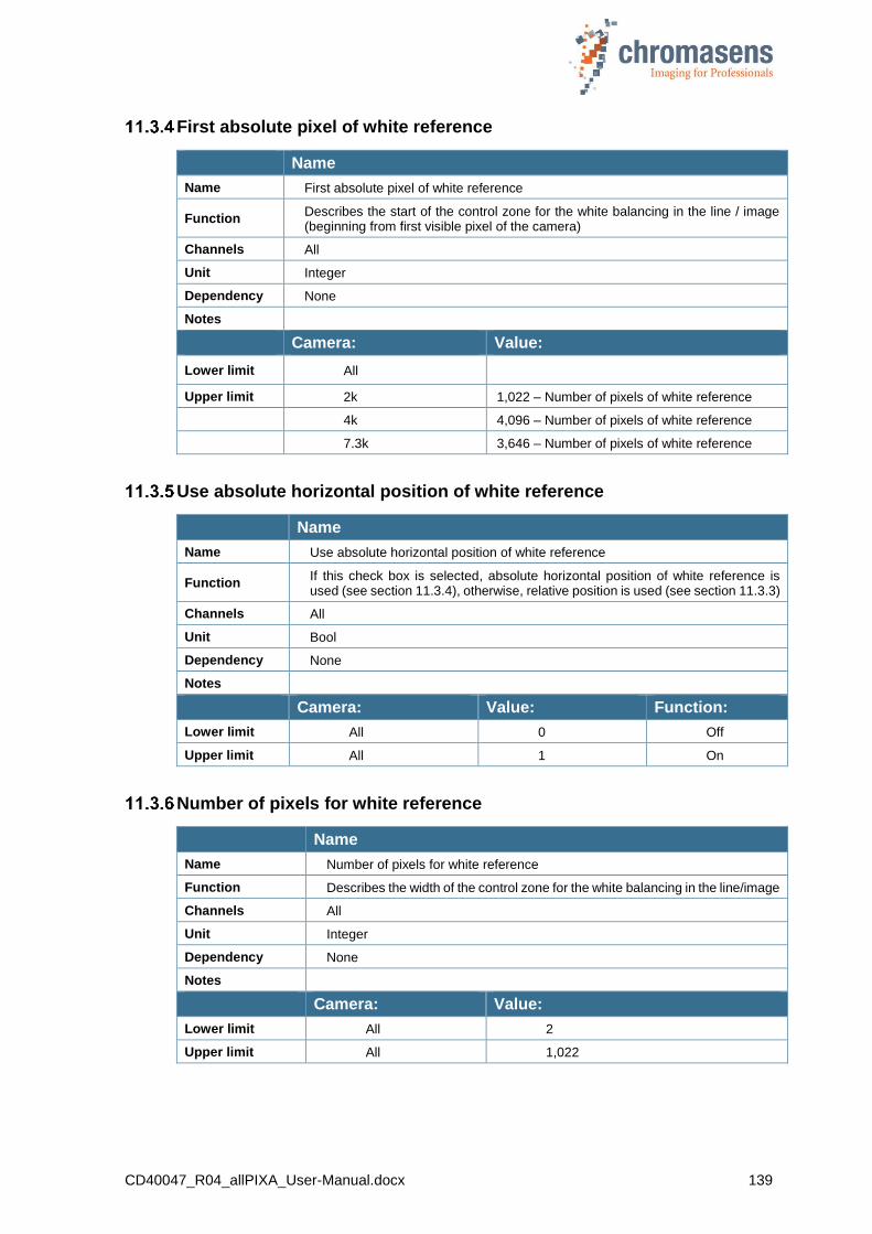
CD40047_R04_allPIXA_User-Manual.docx 139
First absolute pixel of white reference
Name
Name First absolute pixel of white reference
Function Describes the start of the control zone for the white balancing in the line / image (beginning from first visible pixel of the camera)
Channels All
Unit Integer
Dependency None
Notes
Camera: Value:
Lower limit All 0
Upper limit 2k 1,022 – Number of pixels of white reference
4k 4,096 – Number of pixels of white reference
7.3k 3,646 – Number of pixels of white reference
Use absolute horizontal position of white reference
Name
Name Use absolute horizontal position of white reference
Function If this check box is selected, absolute horizontal position of white reference is used (see section 11.3.4), otherwise, relative position is used (see section 11.3.3)
Channels All
Unit Bool
Dependency None
Notes
Camera: Value: Function:
Lower limit All 0 Off
Upper limit All 1 On
Number of pixels for white reference
Name
Name Number of pixels for white reference
Function Describes the width of the control zone for the white balancing in the line/image
Channels All
Unit Integer
Dependency None
Notes
Camera: Value:
Lower limit All 2
Upper limit All 1,022

CD40047_R04_allPIXA_User-Manual.docx 140
First image line for the white reference
Name
Name First image line for the white reference
Function Starts pixel of control zone in transport direction
Channels All
Unit
Dependency Only if the image-synchronized mode is used for white balancing.
Notes
Camera: Value:
Lower limit All 0
Upper limit All Image size – Number of vertical pixels
Number of image lines for the white reference
Name
Name Number of image lines for the white reference
Function Length of control zone in transport direction
Channels All
Unit Integer
Dependency Only if the image synchronized mode is used for white balancing.
Notes
Camera: Value:
Lower limit All 2
Upper limit All 1,022
Number of reference samples (Average)
Name
Name Number of reference samples for white reference
Function Number of ROIs needed for averaging of current video value for closed-loop control, either with synchronization or in free-running mode.
Channels All
Unit Integer
None; 2; 4; 8; 16; 32
Dependency None
Notes
Camera: Value CST:
Lower limit All None
2 samples
4 samples
8 samples
16 samples
Upper limit All 32 samples

CD40047_R04_allPIXA_User-Manual.docx 141
Show white reference border
Name
Name Display white reference borders in the image
Function Displays the border of the control zone with blue lines in the image.
Channels All (Blue: 255; Red and Green: 0)
Unit Bool
Dependency None
Notes Function has to be switched off for taking reference images regarding to black and white correction.
Camera: Value: Function:
Lower limit All 0 Off
Upper limit All 1 On
11.4 White control
Target white reference values
Name
Name Target white reference values
Function Video value for the desired value of the closed loop control for white balancing
Channels
Red, Green, Blue
Odd; Even
Front; Rear
Unit Integer
Linear
Dependency Only takes effect if the Enable continuous white control check box is selected, or during a white reference operation if you click Perform white reference on the toolbar.
Notes
Refers to the white control mark. Inside this area the closed loop control tries to adjust gain to reach these desired values.
Value is a 10-bit video value, output range of the image at the CameraLink port is usually 8-bit range
Camera: Value:
Lower limit All 0
Upper limit All 1023 – dark reference value
This parameter refers to the reference values labeled with (1) in the diagram of section 4.10.
NOTE I The maximum reachable value for the target values is Target values = 1023 - max dark reference value (with active black-level correction). The typical dark reference values are about 4 …16 (in 8 bit) in the raw image date. The maximum dark reference value is 64 (in 8 bit)
NOTE II The level of the target value has to be adapted to the position of the white reference control zone (see Figure 38). For zone 1, the values have to be set to a lower value than for zone 2. If the target values for zone 1 are too high, this results in saturation in the image’s center.

CD40047_R04_allPIXA_User-Manual.docx 142
Figure 38: Sample of raw and theoretical video and dark reference values
Current white reference values
Name
Name Current white reference levels Read-only
Function Video value measured by the camera inside the white control mark, mean value over the defined area and the number of ROI defined for averaging
Channels Red, Green, Blue; Odd; Even Front; Rear
Unit Integer
Linear
Dependency None
Notes
Refers to the white control mark.
10-bit video value during output range of the image at the CameraLink port is usually in the 8-bit range
Camera: Value:
Lower limit All 0
Upper limit All 1023
This parameter refers to the video values labeled with (2) in the diagram of section 4.10.
Enable continuous white control
Name
Name Enable continuous white control
Function Enables the closed loop control for white balancing
Channels all
Unit Bool
Dependency None
Notes
Camera: Value: Function:
Lower limit all 0 Off
Upper limit all 1 On
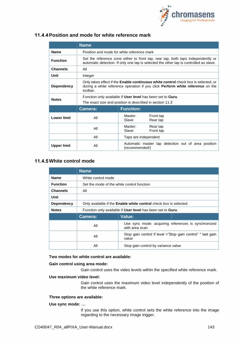
CD40047_R04_allPIXA_User-Manual.docx 143
Position and mode for white reference mark
Name
Name Position and mode for white reference mark
Function Set the reference zone either to front tap, rear tap, both taps independently or automatic detection. If only one tap is selected the other tap is controlled as slave.
Channels All
Unit Integer
Dependency Only takes effect if the Enable continuous white control check box is selected, or during a white reference operation if you click Perform white reference on the
toolbar.
Notes Function only available if User level has been set to Guru.
The exact size and position is described in section 11.3
Camera: Function:
Lower limit All Master: Front tap Slave: Rear tap
All Master: Rear tap Slave: Front tap
All Taps are independent
Upper limit All Automatic master tap detection out of area position (recommended!)
White control mode
Name
Name White control mode
Function Set the mode of the white control function
Channels All
Unit
Dependency Only available if the Enable white control check box is selected.
Notes Function only available if User level has been set to Guru.
Camera: Value:
All Use sync mode: acquiring references is synchronized with area scan
All Stop gain control if level <”Stop gain control” * last gain value
All Stop gain control by variance value
Two modes for white control are available:
Gain control using area mode:
Gain control uses the video levels within the specified white reference mark.
Use maximum video level:
Gain control uses the maximum video level independently of the position of the white reference mark.
Three options are available:
Use sync mode: …
If you use this option, white control sets the white reference into the image regarding to the necessary image trigger.
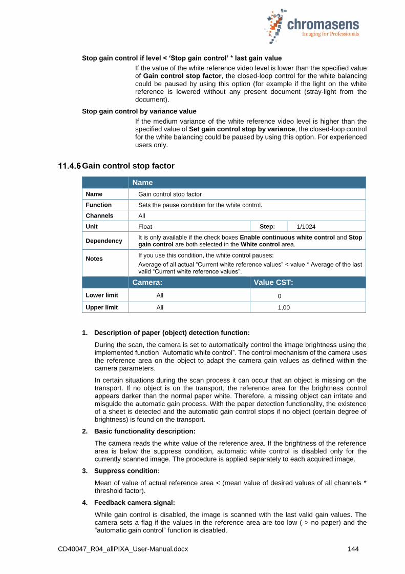
CD40047_R04_allPIXA_User-Manual.docx 144
Stop gain control if level < ‘Stop gain control’ * last gain value
If the value of the white reference video level is lower than the specified value of Gain control stop factor, the closed-loop control for the white balancing could be paused by using this option (for example if the light on the white reference is lowered without any present document (stray-light from the document).
Stop gain control by variance value
If the medium variance of the white reference video level is higher than the specified value of Set gain control stop by variance, the closed-loop control for the white balancing could be paused by using this option. For experienced users only.
Gain control stop factor
Name
Name Gain control stop factor
Function Sets the pause condition for the white control.
Channels All
Unit Float Step: 1/1024
Dependency It is only available if the check boxes Enable continuous white control and Stop gain control are both selected in the White control area.
Notes
If you use this condition, the white control pauses:
Average of all actual “Current white reference values” < value * Average of the last valid “Current white reference values”.
Camera: Value CST:
Lower limit All 0
Upper limit All 1,00
1. Description of paper (object) detection function:
During the scan, the camera is set to automatically control the image brightness using the implemented function “Automatic white control”. The control mechanism of the camera uses the reference area on the object to adapt the camera gain values as defined within the camera parameters.
In certain situations during the scan process it can occur that an object is missing on the transport. If no object is on the transport, the reference area for the brightness control appears darker than the normal paper white. Therefore, a missing object can irritate and misguide the automatic gain process. With the paper detection functionality, the existence of a sheet is detected and the automatic gain control stops if no object (certain degree of brightness) is found on the transport.
2. Basic functionality description:
The camera reads the white value of the reference area. If the brightness of the reference area is below the suppress condition, automatic white control is disabled only for the currently scanned image. The procedure is applied separately to each acquired image.
3. Suppress condition:
Mean of value of actual reference area < (mean value of desired values of all channels * threshold factor).
4. Feedback camera signal:
While gain control is disabled, the image is scanned with the last valid gain values. The camera sets a flag if the values in the reference area are too low (-> no paper) and the “automatic gain control” function is disabled.
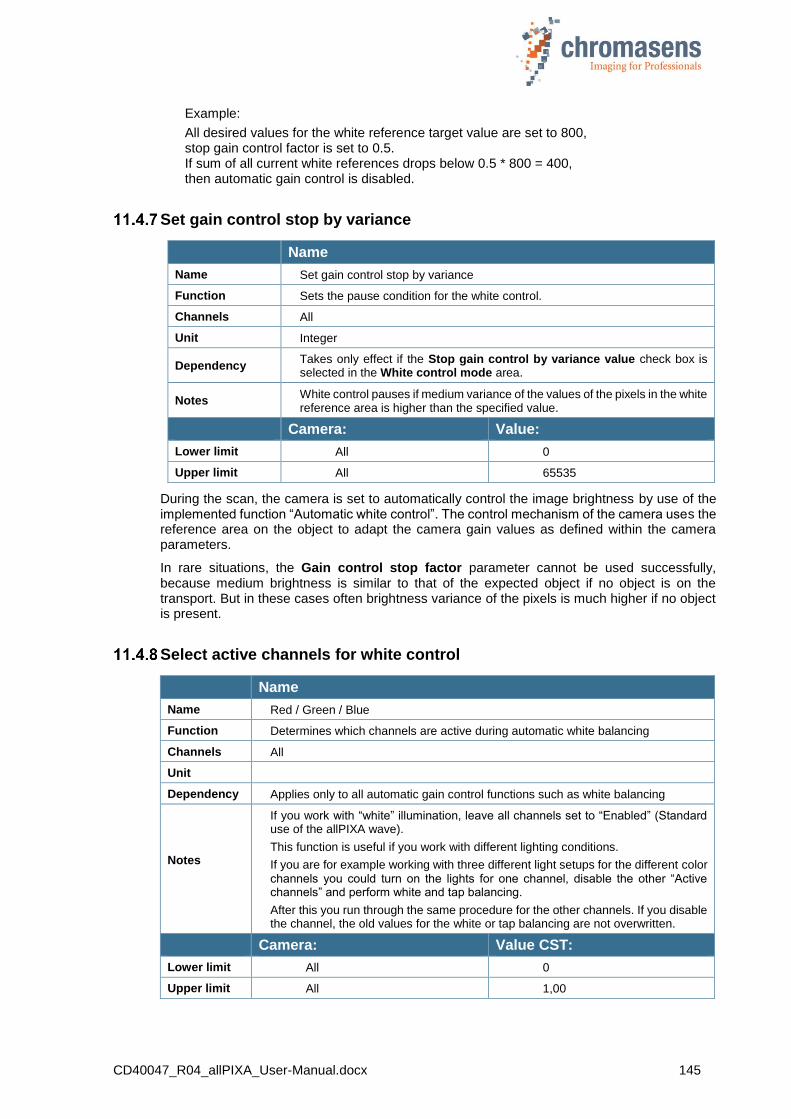
CD40047_R04_allPIXA_User-Manual.docx 145
Example:
All desired values for the white reference target value are set to 800, stop gain control factor is set to 0.5. If sum of all current white references drops below 0.5 * 800 = 400, then automatic gain control is disabled.
Set gain control stop by variance
Name
Name Set gain control stop by variance
Function Sets the pause condition for the white control.
Channels All
Unit Integer
Dependency Takes only effect if the Stop gain control by variance value check box is selected in the White control mode area.
Notes White control pauses if medium variance of the values of the pixels in the white reference area is higher than the specified value.
Camera: Value:
Lower limit All 0
Upper limit All 65535
During the scan, the camera is set to automatically control the image brightness by use of the implemented function “Automatic white control”. The control mechanism of the camera uses the reference area on the object to adapt the camera gain values as defined within the camera parameters.
In rare situations, the Gain control stop factor parameter cannot be used successfully, because medium brightness is similar to that of the expected object if no object is on the transport. But in these cases often brightness variance of the pixels is much higher if no object is present.
Select active channels for white control
Name
Name Red / Green / Blue
Function Determines which channels are active during automatic white balancing
Channels All
Unit
Dependency Applies only to all automatic gain control functions such as white balancing
Notes
If you work with “white” illumination, leave all channels set to “Enabled” (Standard use of the allPIXA wave).
This function is useful if you work with different lighting conditions.
If you are for example working with three different light setups for the different color channels you could turn on the lights for one channel, disable the other “Active channels” and perform white and tap balancing.
After this you run through the same procedure for the other channels. If you disable the channel, the old values for the white or tap balancing are not overwritten.
Camera: Value CST:
Lower limit All 0
Upper limit All 1,00
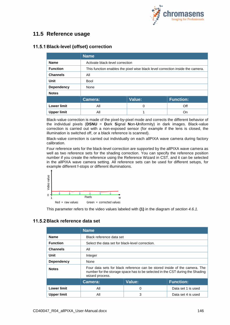
CD40047_R04_allPIXA_User-Manual.docx 146
11.5 Reference usage
Black-level (offset) correction
Name
Name Activate black-level correction
Function This function enables the pixel wise black level correction inside the camera.
Channels All
Unit Bool
Dependency None
Notes
Camera: Value: Function:
Lower limit All 0 Off
Upper limit All 1 On
Black-value correction is made of the pixel-by-pixel mode and corrects the different behavior of the individual pixels (DSNU = Dark Signal Non-Uniformity) in dark images. Black-value correction is carried out with a non-exposed sensor (for example if the lens is closed, the illumination is switched off, or a black reference is scanned).
Black-value correction is carried out individually on each allPIXA wave camera during factory calibration.
Four reference sets for the black-level correction are supported by the allPIXA wave camera as well as two reference sets for the shading correction. You can specify the reference position number if you create the reference using the Reference Wizard in CST, and it can be selected in the allPIXA wave camera setting. All reference sets can be used for different setups, for example different f-stops or different illuminations.
This parameter refers to the video values labeled with (1) in the diagram of section 4.6.1.
Black reference data set
Name
Name Black reference data set
Function Select the data set for black-level correction.
Channels All
Unit Integer
Dependency None
Notes
Four data sets for black reference can be stored inside of the camera. The number for the storage space has to be selected in the CST during the Shading wizard process.
Camera: Value: Function:
Lower limit All 0 Data set 1 is used
Upper limit All 3 Data set 4 is used

CD40047_R04_allPIXA_User-Manual.docx 147
White-level (flat-field) correction
Name
Name Activate whit-level correction
Function This function enables the pixel-wise shading correction inside the camera.
Channels All
Unit Bool
Dependency None
Notes
Camera: Value: Function:
Lower limit All 0 Off
Upper limit All 1 On
Shading correction is made of the pixel-by-pixel mode and corrects the different behavior of the individual pixels in the images (PRNU = Photo Response Non-Uniformity). Additionally, it compensates any non-homogeneities in illumination.
Four reference sets for the shading correction are supported by the allPIXA wave camera, as well as two reference sets for the black-level correction. The reference position number can be entered if the reference is created using the Reference Wizard in CST, and it can be selected in the allPIXA wave camera setting. All reference sets can be used for different setups, for example, for different f-stops or different illuminations.
This parameter refers to the video values labeled with (2) in the diagram of section 4.10.
The internal processing is not limited up to 255@8bit. This means that after the shading correction it is possible to additionally process higher values such as 300, which can be taken without loss into the visible area by using the brightness and contrast control afterwards.
White reference data set
Name
Name White reference data set
Function Select the data set for white-level correction.
Channels All
Unit Integer
Dependency None
Notes
Four data sets for white reference can be stored inside the camera. The number for the storage space has to be selected in the CST during the Shading wizard process.
Camera: Value: Function:
Lower limit All 0 Data set 1 is used
Upper limit All 3 Data set 4 is used
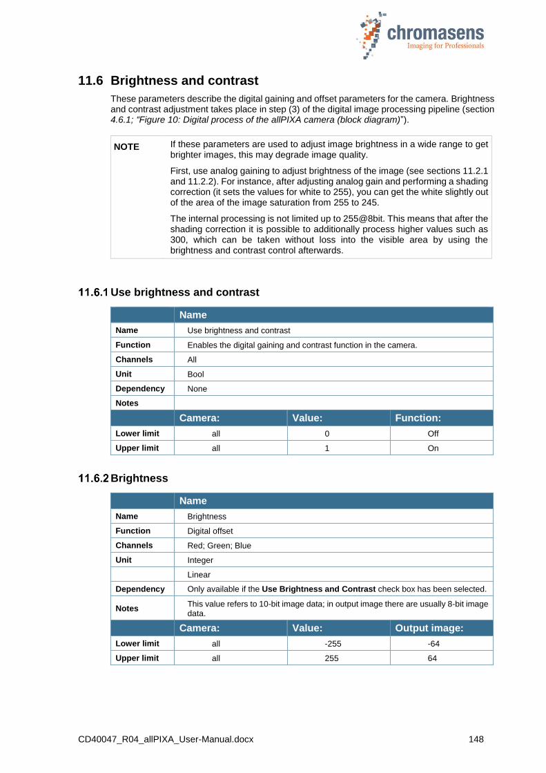
CD40047_R04_allPIXA_User-Manual.docx 148
11.6 Brightness and contrast
These parameters describe the digital gaining and offset parameters for the camera. Brightness and contrast adjustment takes place in step (3) of the digital image processing pipeline (section 4.6.1; “Figure 10: Digital process of the allPIXA camera (block diagram)”).
NOTE If these parameters are used to adjust image brightness in a wide range to get brighter images, this may degrade image quality.
First, use analog gaining to adjust brightness of the image (see sections 11.2.1 and 11.2.2). For instance, after adjusting analog gain and performing a shading correction (it sets the values for white to 255), you can get the white slightly out of the area of the image saturation from 255 to 245.
The internal processing is not limited up to 255@8bit. This means that after the shading correction it is possible to additionally process higher values such as 300, which can be taken without loss into the visible area by using the brightness and contrast control afterwards.
Use brightness and contrast
Name
Name Use brightness and contrast
Function Enables the digital gaining and contrast function in the camera.
Channels All
Unit Bool
Dependency None
Notes
Camera: Value: Function:
Lower limit all 0 Off
Upper limit all 1 On
Brightness
Name
Name Brightness
Function Digital offset
Channels Red; Green; Blue
Unit Integer
Linear
Dependency Only available if the Use Brightness and Contrast check box has been selected.
Notes This value refers to 10-bit image data; in output image there are usually 8-bit image data.
Camera: Value: Output image:
Lower limit all -255 -64
Upper limit all 255 64
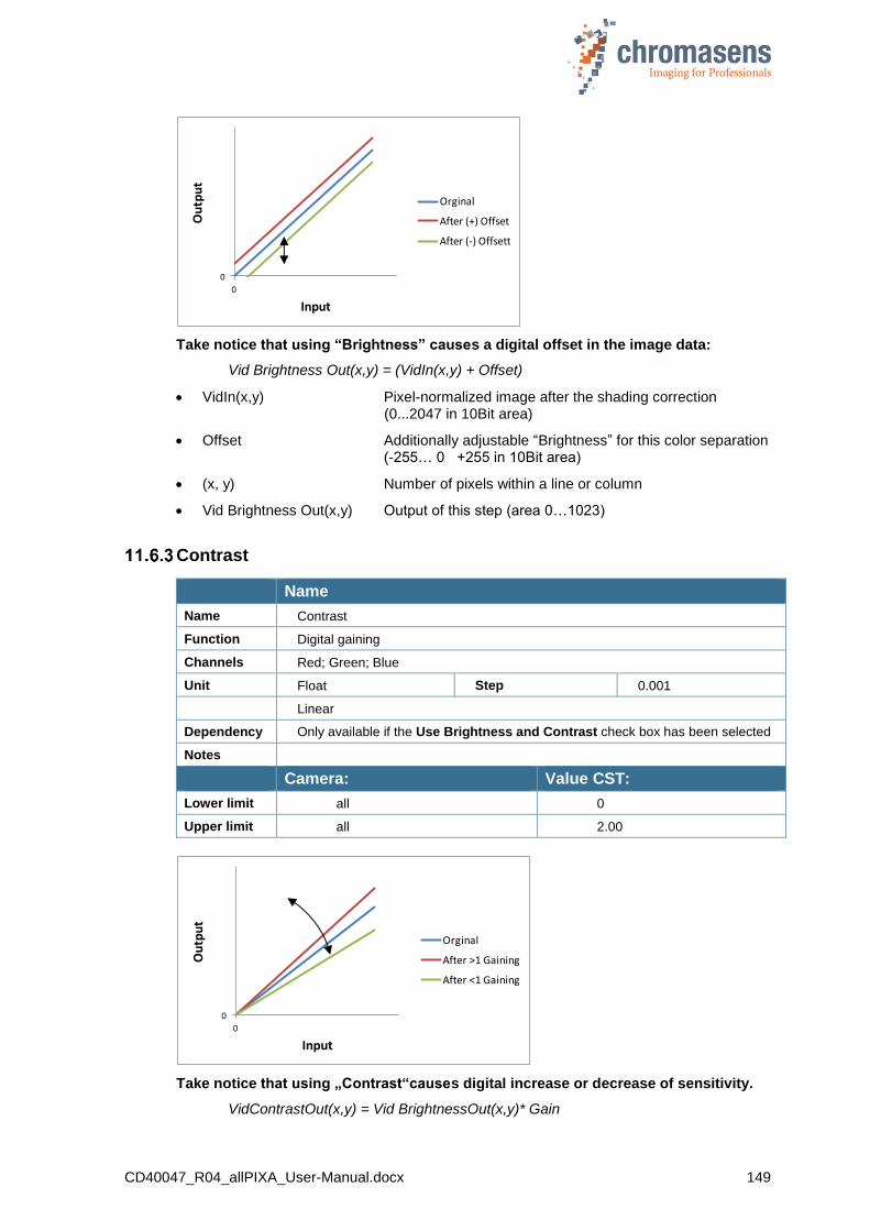
CD40047_R04_allPIXA_User-Manual.docx 149
Take notice that using “Brightness” causes a digital offset in the image data:
Vid Brightness Out(x,y) = (VidIn(x,y) + Offset)
VidIn(x,y) Pixel-normalized image after the shading correction (0...2047 in 10Bit area)
Offset Additionally adjustable “Brightness” for this color separation (-255… 0 +255 in 10Bit area)
(x, y) Number of pixels within a line or column
Vid Brightness Out(x,y) Output of this step (area 0…1023)
Contrast
Name
Name Contrast
Function Digital gaining
Channels Red; Green; Blue
Unit Float Step 0.001
Linear
Dependency Only available if the Use Brightness and Contrast check box has been selected
Notes
Camera: Value CST:
Lower limit all 0
Upper limit all 2.00
Take notice that using „Contrast“causes digital increase or decrease of sensitivity.
VidContrastOut(x,y) = Vid BrightnessOut(x,y)* Gain
0
0
Output
Input
Orginal
After (+) Offset
After (-) Offsett
0
0
Output
Input
Orginal
After >1 Gaining
After <1 Gaining
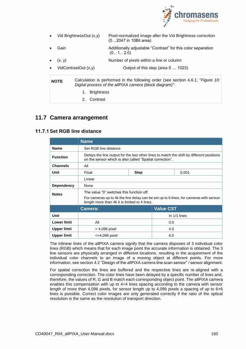
CD40047_R04_allPIXA_User-Manual.docx 150
Vid BrightnessOut (x,y) Pixel-normalized image after the Vid Brightness correction (0…2047 in 10Bit area)
Gain Additionally adjustable “Contrast” for this color separation (0…1…2.0)
(x, y) Number of pixels within a line or column
VidContrastOut (x,y) Output of this step (area 0 … 1023)
NOTE Calculation is performed in the following order (see section 4.6.1; “Figure 10: Digital process of the allPIXA camera (block diagram)”:
1. Brightness
2. Contrast
11.7 Camera arrangement
Set RGB line distance
Name
Name Set RGB line distance
Function Delays the line output for the two other lines to match the shift by different positions on the sensor which is also called “Spatial correction”.
Channels All
Unit Float Step 0,001
Linear
Dependency None
Notes
The value “0” switches this function off.
For cameras up to 4k the line delay can be set up to 6 lines, for cameras with sensor length more than 4k it is limited to 4 lines.
Camera: Value CST
Unit In 1/1 lines
Lower limit All 0.0
Upper limit > 4,096 pixel 4.0
Upper limit <=4,096 pixel 6.0
The trilinear lines of the allPIXA camera signify that the camera disposes of 3 individual color lines (RGB) which means that for each image point the accurate information is obtained. The 3 line sensors are physically arranged in different locations, resulting in the acquirement of the individual color channels to an image of a moving object at different points. For more information, see section 4.2 “Design of the allPIXA camera line scan sensor” / sensor alignment.
For spatial correction the lines are buffered and the respective lines are re-aligned with a corresponding correction. The color lines have been delayed by a specific number of lines and, therefore, the values of R, G and B match each corresponding object point. The allPIXA camera enables this compensation with up to 4+4 lines spacing according to the camera with sensor length of more than 4,096 pixels, for sensor length up to 4,096 pixels a spacing of up to 6+6 lines is possible. Correct color images are only generated correctly if the ratio of the optical resolution is the same as the resolution of transport direction.
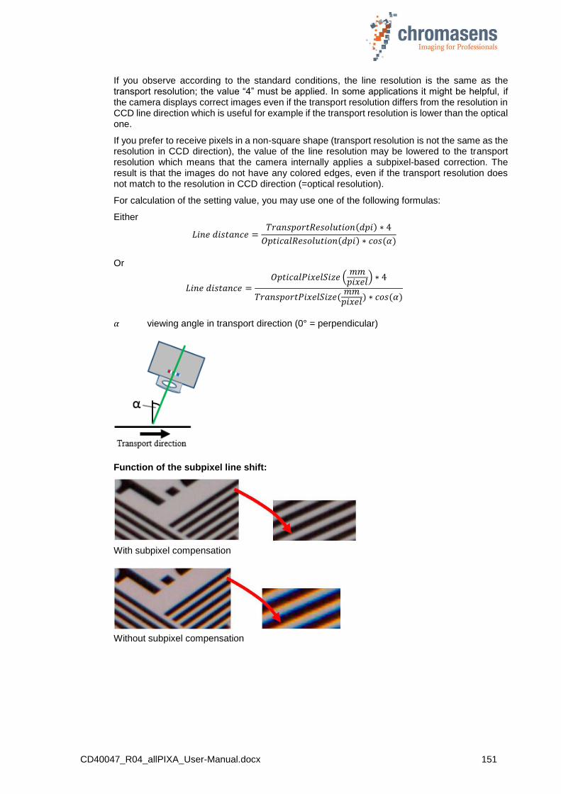
CD40047_R04_allPIXA_User-Manual.docx 151
If you observe according to the standard conditions, the line resolution is the same as the transport resolution; the value “4” must be applied. In some applications it might be helpful, if the camera displays correct images even if the transport resolution differs from the resolution in CCD line direction which is useful for example if the transport resolution is lower than the optical one.
If you prefer to receive pixels in a non-square shape (transport resolution is not the same as the resolution in CCD direction), the value of the line resolution may be lowered to the transport resolution which means that the camera internally applies a subpixel-based correction. The result is that the images do not have any colored edges, even if the transport resolution does not match to the resolution in CCD direction (=optical resolution).
For calculation of the setting value, you may use one of the following formulas:
Either
𝐿𝑖𝑛𝑒 𝑑𝑖𝑠𝑡𝑎𝑛𝑐𝑒 =𝑇𝑟𝑎𝑛𝑠𝑝𝑜𝑟𝑡𝑅𝑒𝑠𝑜𝑙𝑢𝑡𝑖𝑜𝑛(𝑑𝑝𝑖) ∗ 4
𝑂𝑝𝑡𝑖𝑐𝑎𝑙𝑅𝑒𝑠𝑜𝑙𝑢𝑡𝑖𝑜𝑛(𝑑𝑝𝑖) ∗ 𝑐𝑜𝑠 (𝛼)
Or
𝐿𝑖𝑛𝑒 𝑑𝑖𝑠𝑡𝑎𝑛𝑐𝑒 =𝑂𝑝𝑡𝑖𝑐𝑎𝑙𝑃𝑖𝑥𝑒𝑙𝑆𝑖𝑧𝑒 (
𝑚𝑚𝑝𝑖𝑥𝑒𝑙
) ∗ 4
𝑇𝑟𝑎𝑛𝑠𝑝𝑜𝑟𝑡𝑃𝑖𝑥𝑒𝑙𝑆𝑖𝑧𝑒(𝑚𝑚
𝑝𝑖𝑥𝑒𝑙) ∗ 𝑐𝑜𝑠 (𝛼)
𝛼 viewing angle in transport direction (0° = perpendicular)
Function of the subpixel line shift:
With subpixel compensation
Without subpixel compensation
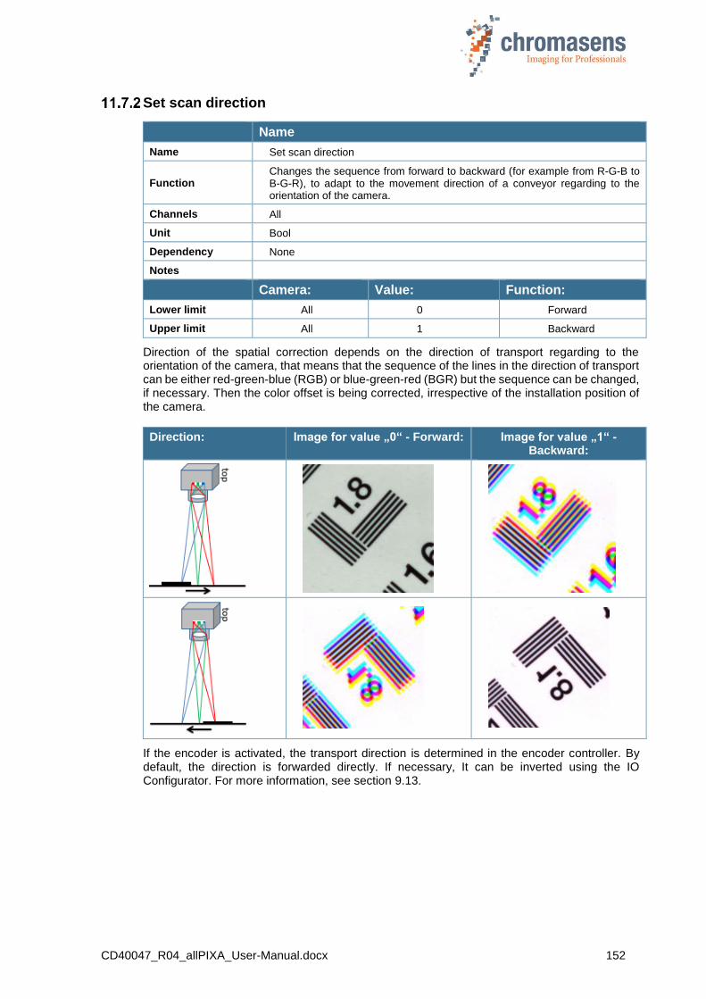
CD40047_R04_allPIXA_User-Manual.docx 152
Set scan direction
Name
Name Set scan direction
Function Changes the sequence from forward to backward (for example from R-G-B to B-G-R), to adapt to the movement direction of a conveyor regarding to the orientation of the camera.
Channels All
Unit Bool
Dependency None
Notes
Camera: Value: Function:
Lower limit All 0 Forward
Upper limit All 1 Backward
Direction of the spatial correction depends on the direction of transport regarding to the orientation of the camera, that means that the sequence of the lines in the direction of transport can be either red-green-blue (RGB) or blue-green-red (BGR) but the sequence can be changed, if necessary. Then the color offset is being corrected, irrespective of the installation position of the camera.
Direction: Image for value „0“ - Forward: Image for value „1“ - Backward:
If the encoder is activated, the transport direction is determined in the encoder controller. By default, the direction is forwarded directly. If necessary, It can be inverted using the IO Configurator. For more information, see section 9.13.
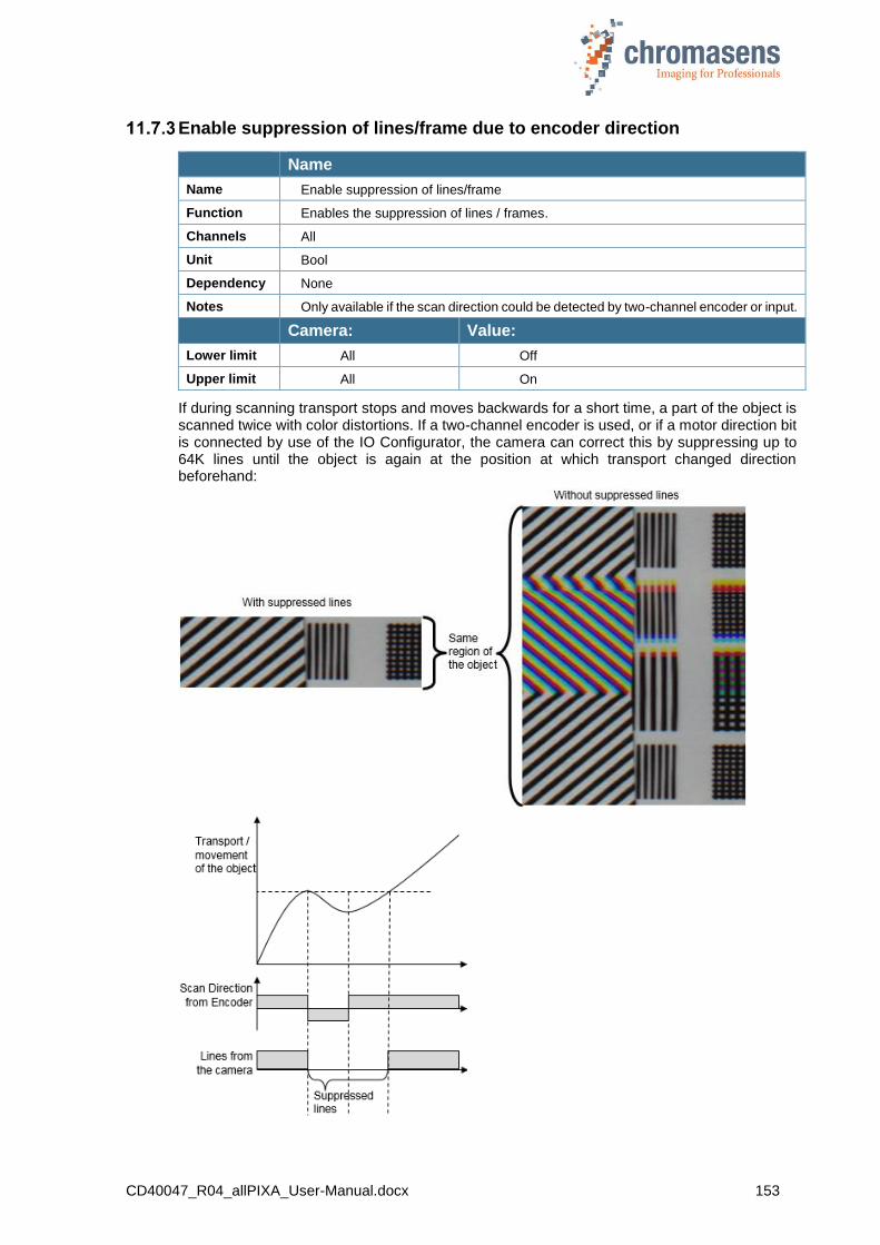
CD40047_R04_allPIXA_User-Manual.docx 153
Enable suppression of lines/frame due to encoder direction
Name
Name Enable suppression of lines/frame
Function Enables the suppression of lines / frames.
Channels All
Unit Bool
Dependency None
Notes Only available if the scan direction could be detected by two-channel encoder or input.
Camera: Value:
Lower limit All Off
Upper limit All On
If during scanning transport stops and moves backwards for a short time, a part of the object is scanned twice with color distortions. If a two-channel encoder is used, or if a motor direction bit is connected by use of the IO Configurator, the camera can correct this by suppressing up to 64K lines until the object is again at the position at which transport changed direction beforehand:

CD40047_R04_allPIXA_User-Manual.docx 154
Mode of lines/frame suppression
Name
Name Suppress lines/frames mode
Function Defines the direction for suppression
Channels All
Unit Bool
Dependency None
Notes Only available if the Enable suppression of lines/frames check box is selected.
Camera: Value:
Lower limit All Suppress lines against selected direction
Upper limit All Suppress lines in selected direction
11.8 Image Sizes
Number of scan lines per image
Name
Name Number of scan lines per image
Function Image size in transport direction
Channels All
Unit Integer
Dependency Only in frame scan mode
Notes
Camera: Value:
Lower limit All 1
Upper limit All 1048575
If the camera is supplied with information of the frame start at CC3 or CC4 (via CameraLink) or at the IO-Port, it is able to generate VSync and frame valid signal. The external signals have to be connected with the IO Configurator to the internal functions in CST. Without these signals the camera is able to send images in free-running mode.
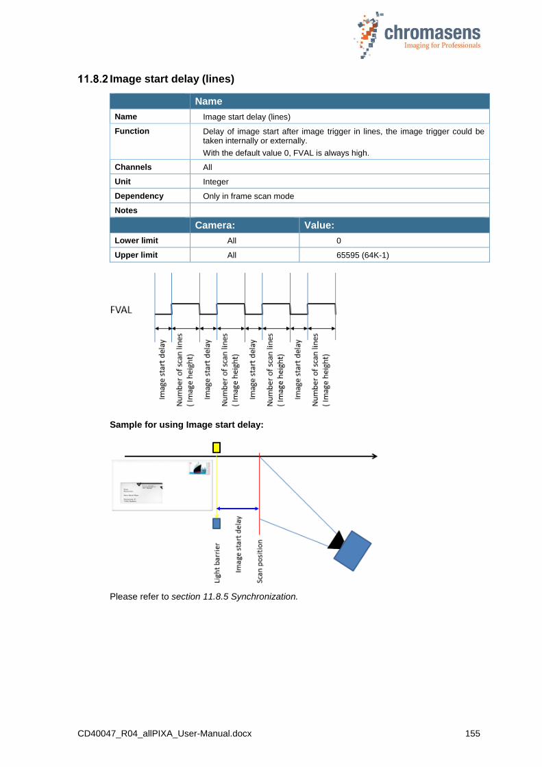
CD40047_R04_allPIXA_User-Manual.docx 155
Image start delay (lines)
Name
Name Image start delay (lines)
Function Delay of image start after image trigger in lines, the image trigger could be taken internally or externally.
With the default value 0, FVAL is always high.
Channels All
Unit Integer
Dependency Only in frame scan mode
Notes
Camera: Value:
Lower limit All 0
Upper limit All 65595 (64K-1)
Sample for using Image start delay:
Please refer to section 11.8.5 Synchronization.

CD40047_R04_allPIXA_User-Manual.docx 156
Scan line length
Name
Name Scan line length
Function Image width
Channels All
Unit Integer
Dependency None
Notes The numbers of pixel are centered to the visible area of the camera.
Camera: Value:
Lower limit All 2
Upper limit
2k: 2,048
4k 4,096
7.3k 7,300 (7,296 by default)
There are 2 different cases for scan line length:
Original: Scan line length equal to sensor length:
Scan line length is set to the sensor length of the camera, for example 4096.
Cropping: Scan line length shorter than sensor length:
The camera captures an image from a ROI which is centered in the sensor.

CD40047_R04_allPIXA_User-Manual.docx 157
Horizontal binning
Name
Name Horizontal binning
Function Enables horizontal pixel reduction. Several neighbored pixels are averaged to one single pixel which is output.
Channels All
Unit Integer
Dependency
Due to the restrictions of some frame grabbers, only special module numbers of pixels are possible.
For most frame grabbers, the number of camera link clock cycles and the number of pixels must be an integer value, sometimes with an additional modulo of for example 8 .
You must test the number of pixel for your application and combination of camera settings and used frame grabber.
Notes
Only the amount of output data per line is affected.
0: 1/1 ( no reduction) 3: 1/8 1: 1/2 4: 1/16 2: 1/4
Camera: Value: Function:
Lower limit All 0 Off
Upper limit All 4 1/ 16 reduction
Number of suppressed lines
Name
Name Number of suppressed lines
Function Number of lines which are ignored for output; causes reduction of data or resolution in transport direction.
Channels All
Unit Integer
Dependency None
Notes
Camera Value
Lower limit All 0
Upper limit All 255
NOTE This function is helpful for doing testing and system setups. If there is no encoder signal available and the speed for testing and setup is much lower than the nominal speed, the system can be tested with nominal integration time and gaining value.
Afterwards, the speed is as follows:
Vred=Vnominal / (1 + Number of suppressed lines)

CD40047_R04_allPIXA_User-Manual.docx 158
11.9 Synchronization (frame synchronization)
The allPIXA camera is able to generate frame information. If you want to use this mode, you have to specify values for several parameters.
NOTE I First, the hardware ports have to be connected to the internal functions of the camera. Therefore, use the IO Configurator in CST and refer to section 9.13 IO Configurator.
NOTE II In case the camera is used in the “Triggered Frame Scan” with active LineTrigger or Encoder, the linesync (Encoder or LineTrigger) must fit some pulses before light barrier input.
Triggered frame scan
Name
Name Triggered frame scan
Function Enables the triggered frame scan modes
Channels All
Unit Integer
Dependency None
Notes
Camera Function
Lower limit All Free-running
All Use start conditions only
All Reserved
Upper limit All Start and stop condition
There are 4 different modes:
a) Free-running: FVAL is generated continuously, depending on Number of scan lines (Image height) and Image start delay.
b) Use start condition:
FVAL is generated after receiving a trigger signal. The frame is delayed by the value of Image start delay and image length is defined by Number of scan lines (Image height).
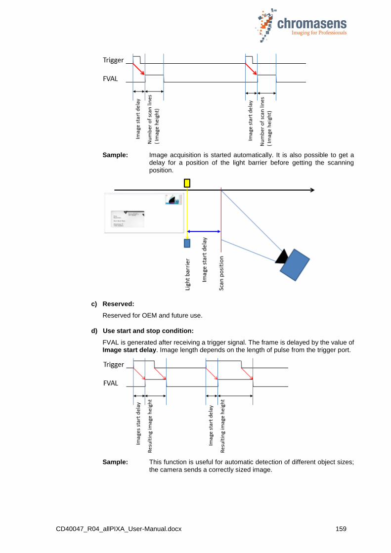
CD40047_R04_allPIXA_User-Manual.docx 159
Sample: Image acquisition is started automatically. It is also possible to get a delay for a position of the light barrier before getting the scanning position.
c) Reserved:
Reserved for OEM and future use.
d) Use start and stop condition:
FVAL is generated after receiving a trigger signal. The frame is delayed by the value of Image start delay. Image length depends on the length of pulse from the trigger port.
Sample: This function is useful for automatic detection of different object sizes; the camera sends a correctly sized image.

CD40047_R04_allPIXA_User-Manual.docx 160
For information about Number of scan lines and Image start delay, see section 11.8.2.
Scan lines after stop
Name
Name Scan lines after stop
Function Sets the number of lines added to the image after the stop condition.
Channels All
Unit Integer
Dependency Only available if Use start and stop condition is selected at Triggered frame scan
Notes
Camera Value
Lower limit All 0
Upper limit All 65535
Sample: If the transported object is not rotated, the result with Start and Stop condition is not satisfactory.
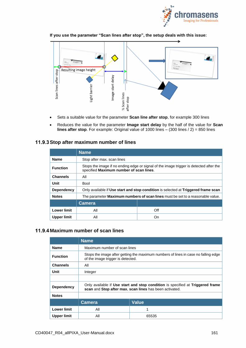
CD40047_R04_allPIXA_User-Manual.docx 161
If you use the parameter “Scan lines after stop”, the setup deals with this issue:
Sets a suitable value for the parameter Scan line after stop, for example 300 lines
Reduces the value for the parameter Image start delay by the half of the value for Scan lines after stop. For example: Original value of 1000 lines – (300 lines / 2) = 850 lines
Stop after maximum number of lines
Name
Name Stop after max. scan lines
Function Stops the image if no ending edge or signal of the image trigger is detected after the specified Maximum number of scan lines.
Channels All
Unit Bool
Dependency Only available if Use start and stop condition is selected at Triggered frame scan
Notes The parameter Maximum numbers of scan lines must be set to a reasonable value.
Camera
Lower limit All Off
Upper limit All On
Maximum number of scan lines
Name
Name Maximum number of scan lines
Function Stops the image after getting the maximum numbers of lines in case no falling edge of the image trigger is detected.
Channels All
Unit Integer
Dependency Only available if Use start and stop condition is specified at Triggered frame scan and Stop after max. scan lines has been activated.
Notes
Camera Value
Lower limit All 1
Upper limit All 65535
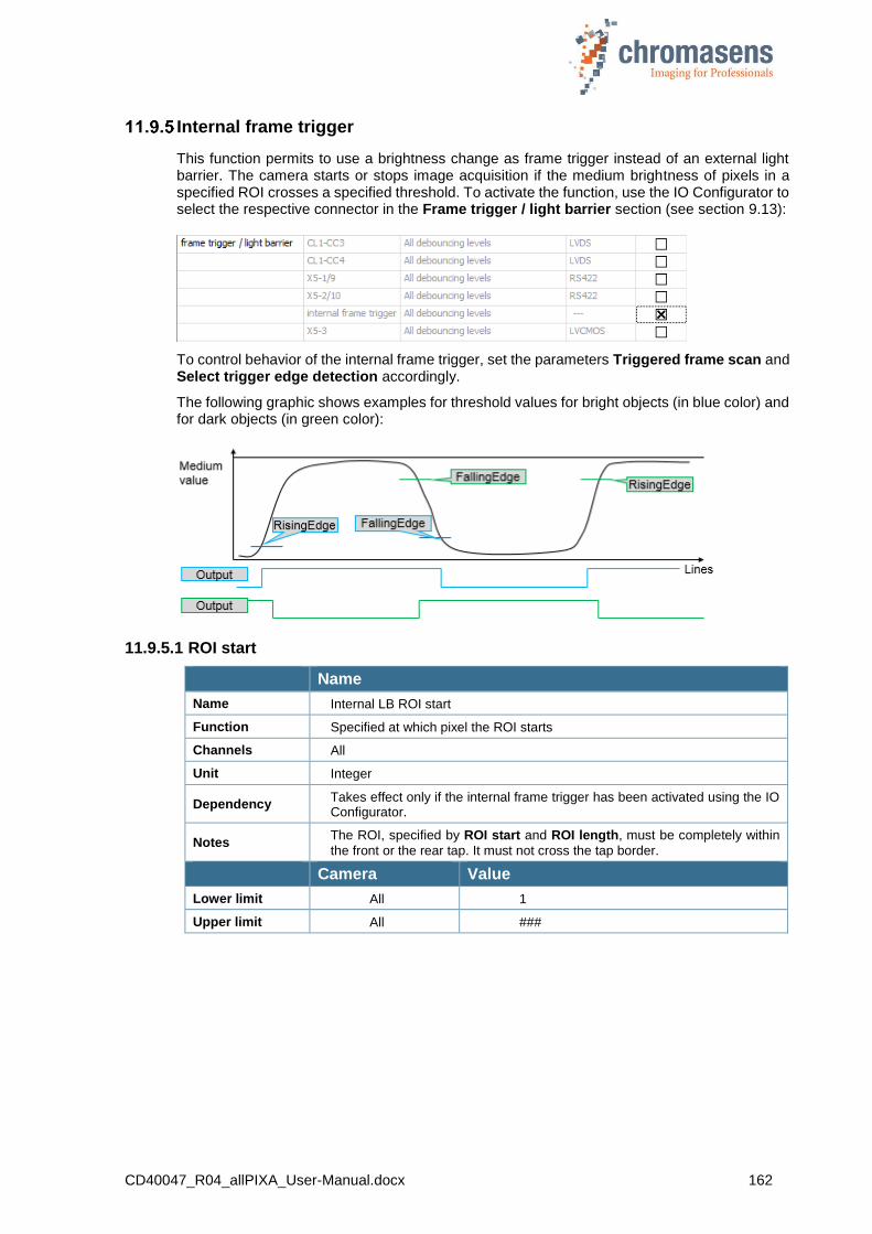
CD40047_R04_allPIXA_User-Manual.docx 162
Internal frame trigger
This function permits to use a brightness change as frame trigger instead of an external light barrier. The camera starts or stops image acquisition if the medium brightness of pixels in a specified ROI crosses a specified threshold. To activate the function, use the IO Configurator to select the respective connector in the Frame trigger / light barrier section (see section 9.13):
To control behavior of the internal frame trigger, set the parameters Triggered frame scan and Select trigger edge detection accordingly.
The following graphic shows examples for threshold values for bright objects (in blue color) and for dark objects (in green color):
11.9.5.1 ROI start
Name
Name Internal LB ROI start
Function Specified at which pixel the ROI starts
Channels All
Unit Integer
Dependency Takes effect only if the internal frame trigger has been activated using the IO Configurator.
Notes The ROI, specified by ROI start and ROI length, must be completely within
the front or the rear tap. It must not cross the tap border.
Camera Value
Lower limit All 1
Upper limit All ###
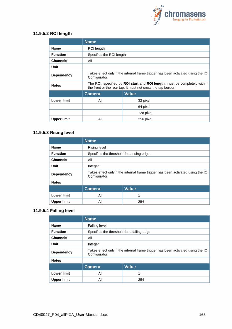
CD40047_R04_allPIXA_User-Manual.docx 163
11.9.5.2 ROI length
Name
Name ROI length
Function Specifies the ROI length
Channels All
Unit
Dependency Takes effect only if the internal frame trigger has been activated using the IO Configurator.
Notes The ROI, specified by ROI start and ROI length, must be completely within the front or the rear tap. It must not cross the tap border.
Camera Value
Lower limit All 32 pixel
64 pixel
128 pixel
Upper limit All 256 pixel
11.9.5.3 Rising level
Name
Name Rising level
Function Specifies the threshold for a rising edge.
Channels All
Unit Integer
Dependency Takes effect only if the internal frame trigger has been activated using the IO Configurator.
Notes
Camera Value
Lower limit All 1
Upper limit All 254
11.9.5.4 Falling level
Name
Name Falling level
Function Specifies the threshold for a falling edge
Channels All
Unit Integer
Dependency Takes effect only if the internal frame trigger has been activated using the IO Configurator.
Notes
Camera Value
Lower limit All 1
Upper limit All 254
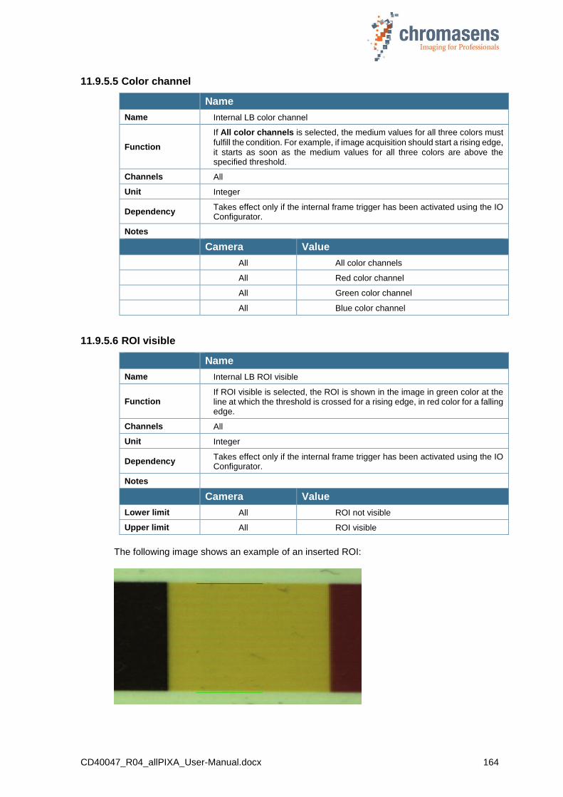
CD40047_R04_allPIXA_User-Manual.docx 164
11.9.5.5 Color channel
Name
Name Internal LB color channel
Function
If All color channels is selected, the medium values for all three colors must
fulfill the condition. For example, if image acquisition should start a rising edge, it starts as soon as the medium values for all three colors are above the specified threshold.
Channels All
Unit Integer
Dependency Takes effect only if the internal frame trigger has been activated using the IO Configurator.
Notes
Camera Value
All All color channels
All Red color channel
All Green color channel
All Blue color channel
11.9.5.6 ROI visible
Name
Name Internal LB ROI visible
Function If ROI visible is selected, the ROI is shown in the image in green color at the line at which the threshold is crossed for a rising edge, in red color for a falling edge.
Channels All
Unit Integer
Dependency Takes effect only if the internal frame trigger has been activated using the IO Configurator.
Notes
Camera Value
Lower limit All ROI not visible
Upper limit All ROI visible
The following image shows an example of an inserted ROI:
CD40047_R04_allPIXA_User-Manual.docx 165
Input debouncing speed (Frame trigger)
To trigger images from an external source, the signal of the trigger, for example from a light barrier, must be connected to the hardware ports of the camera; this could be done by means of the frame grabber using CC-bits or the D-Sub 15 IO port on the camera.
These external signals must be connected to the internal functions (LB 0 to LB 3) which have to be selected regarding to signal duration and signal quality of the trigger using the IO Configurator in CST.
The single inputs have different properties regarding the debouncing speed.
Name
Name Input debouncing speed
Function Enables the internal ports to be used as frame trigger
Channels All
Unit
Dependency Only active if Use start condition or Use start and stop condition is selected at Triggered frame scan.
Notes
Camera Value
All Peakholder (LB2)
All 35 ns (LB1)
All 4 image lines (LB3)
All 70 image lines (LB0)
By using this option you can select the internal function ports for image trigger. The external ports (for example CC3 from Camera Link) must be connected to internal functions using the IO Configurator in CST (see section 9.13).
There are different methods for debouncing the signal:
LB 0: 60 output lines
LB 1: 4 clock pulses ~ 35 ns
LB 2: no debouncing, peak holder
LB 3: 4 output lines
Selection of the internal functions for triggering the image is done in CST.
Scan pattern
Name
Name Select trigger edge detection
Function This determines whether the trigger is evaluated at the rising or at the falling edge.
Channels All
Unit
Dependency Only active if Use start condition or Use start and stop condition is selected.
Notes
Camera Value
All Falling edge
All Rising edge

CD40047_R04_allPIXA_User-Manual.docx 166
This function determines whether the image starts at rising or falling edge of the signal. Setting differs for Use start condition only and for Start and stop condition.
The state of the ports is checked synchronized with the line frequency clock. At each rising edge of the line frequency clock, the status is checked and the debouncing condition must be complied with.
The following tables show suitable sequences and their function (screen shots from CST):
If Use start condition only is selected as triggered frame scan parameter:
If Start and stop condition is selected as triggered frame scan parameter:
1. Use start condition only
Select trigger edge detection Function
These sequences cause a frame start at a rising edge:
These sequences cause a frame start at a falling edge.
Trigger
Image
Trigger
Image

CD40047_R04_allPIXA_User-Manual.docx 167
2. Use start and stop condition
Select trigger edge detection Function
These sequences cause a frame start at a rising edge and the frame stop at a falling edge.
These sequences cause a frame start at a falling edge and the frame stop at a rising edge.
Master/slave
Name
Name Set global master-slave mode
Function Synchronization of more than one allPIXA cameras
Channels All
Unit
Dependency The slave camera(s) must know whether the master runs with encoder/line-trigger or in free-running mode!
Notes
The position of the image in transport direction (Y) of each camera could be set separately. The image length is defined by the master.
Also the position (X + Y) and the size of the white reference could be set separately.
Camera Value
Lower limit All Get master-slave from setting
All Camera acts as master
All Camera acts as slave
Upper limit All Auto-select by input
If more than one camera is used, for example in print inspection, these cameras must be synchronized very accurately to achieve the best system performance.
Principle of the master-slave synchronization:
The trigger signals from light barrier and/or encoder are connected to the master camera only.
This could be done with the CC-bits via the frame grabber or directly connected to the master allPIXA camera. This trigger information is transferred via the master-slave interface to the slave camera(s). Due to this synchronization interface all cameras are running with exactly the same timing for lines and optional frames.
Trigger
Image
Trigger
Image

CD40047_R04_allPIXA_User-Manual.docx 168
NOTE This parameter is part of a setting. It may change from one setting to another.
If the parameter is the same in each setting the master-slave mode can be set global (see section 11.15.1)
Parameter and region of interest of the master-slave synchronization:
Line – and Image trigger
MASTER SLAVE(S)
Spike suppression
State machine
internal Sync
Wait for
First relative pixel for white reference
(Tag x2A3) Lines
Wait for
First relative pixel for white reference
(Tag x2A3) Lines
Wait for
Image start delay (Tag x230)
Lines
Free running, Only image start, Image
start and stop Oversize, for all cameras
IO-Config
Image + line trigger
Wait for
Image start delay
(Tag x230) Lines
Image
Image WhiteRef-ROI WhiteRef-ROI
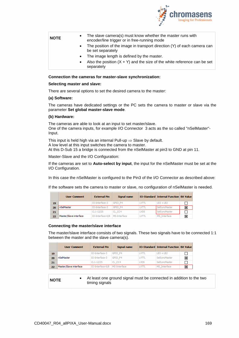
CD40047_R04_allPIXA_User-Manual.docx 169
NOTE The slave camera(s) must know whether the master runs with
encoder/line trigger or in free-running mode
The position of the image in transport direction (Y) of each camera can be set separately
The image length is defined by the master.
Also the position (X + Y) and the size of the white reference can be set separately
Connection the cameras for master-slave synchronization:
Selecting master and slave:
There are several options to set the desired camera to the master:
(a) Software:
The cameras have dedicated settings or the PC sets the camera to master or slave via the parameter Set global master-slave mode.
(b) Hardware:
The cameras are able to look at an input to set master/slave. One of the camera inputs, for example I/O Connector 3 acts as the so called "nSelMaster"-Input.
This input is held high via an internal Pull-up Slave by default. A low level at this input switches the camera to master. At this D-Sub 15 a bridge is connected from the nSelMaster at pin3 to GND at pin 11.
Master-Slave and the I/O Configuration:
If the cameras are set to Auto-select by input, the input for the nSelMaster must be set at the I/O Configuration.
In this case the nSelMaster is configured to the Pin3 of the I/O Connector as described above:
If the software sets the camera to master or slave, no configuration of nSelMaster is needed.
Connecting the master/slave interface
The master/slave interface consists of two signals. These two signals have to be connected 1:1 between the master and the slave camera(s).
NOTE At least one ground signal must be connected in addition to the two
timing signals
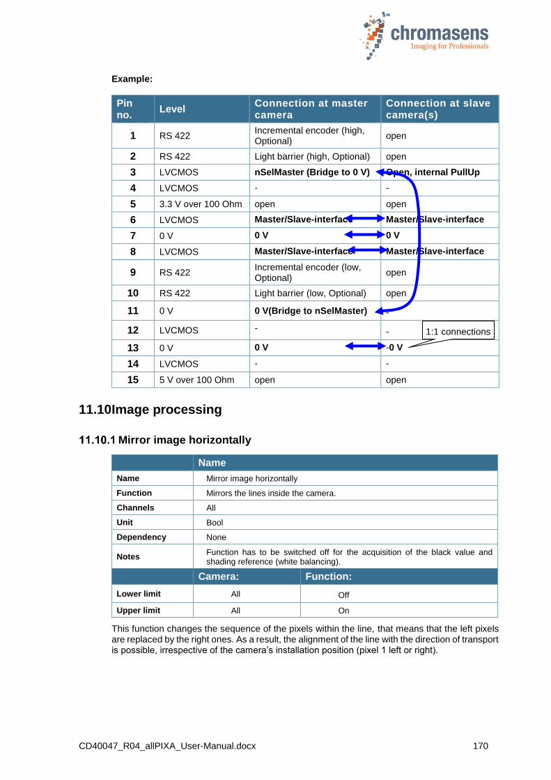
CD40047_R04_allPIXA_User-Manual.docx 170
Example:
Pin no.
Level Connection at master camera
Connection at slave camera(s)
1 RS 422 Incremental encoder (high, Optional)
open
2 RS 422 Light barrier (high, Optional) open
3 LVCMOS nSelMaster (Bridge to 0 V) Open, internal PullUp
4 LVCMOS - -
5 3.3 V over 100 Ohm open open
6 LVCMOS Master/Slave-interface Master/Slave-interface
7 0 V 0 V 0 V
8 LVCMOS Master/Slave-interface Master/Slave-interface
9 RS 422 Incremental encoder (low, Optional)
open
10 RS 422 Light barrier (low, Optional) open
11 0 V 0 V(Bridge to nSelMaster) -
12 LVCMOS - -
13 0 V 0 V -0 V
14 LVCMOS - -
15 5 V over 100 Ohm open open
11.10 Image processing
Mirror image horizontally
Name
Name Mirror image horizontally
Function Mirrors the lines inside the camera.
Channels All
Unit Bool
Dependency None
Notes Function has to be switched off for the acquisition of the black value and shading reference (white balancing).
Camera: Function:
Lower limit All Off
Upper limit All On
This function changes the sequence of the pixels within the line, that means that the left pixels are replaced by the right ones. As a result, the alignment of the line with the direction of transport is possible, irrespective of the camera’s installation position (pixel 1 left or right).
1:1 connections
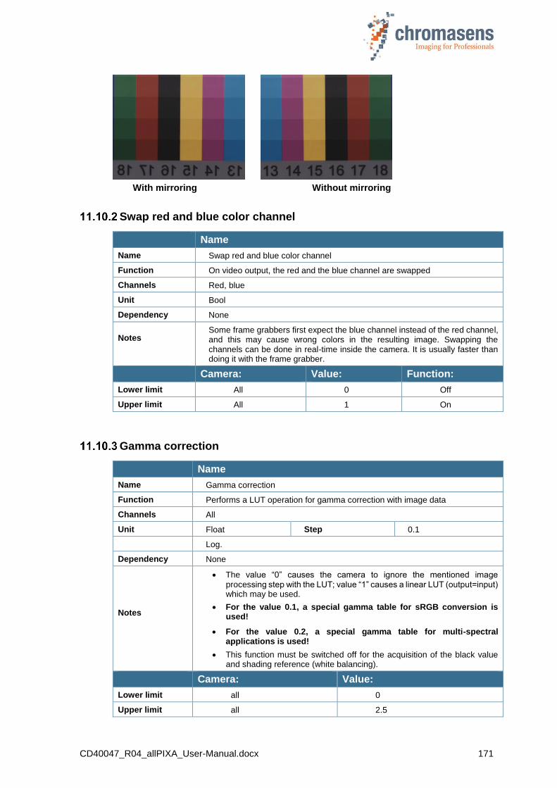
CD40047_R04_allPIXA_User-Manual.docx 171
With mirroring Without mirroring
Swap red and blue color channel
Name
Name Swap red and blue color channel
Function On video output, the red and the blue channel are swapped
Channels Red, blue
Unit Bool
Dependency None
Notes
Some frame grabbers first expect the blue channel instead of the red channel, and this may cause wrong colors in the resulting image. Swapping the channels can be done in real-time inside the camera. It is usually faster than doing it with the frame grabber.
Camera: Value: Function:
Lower limit All 0 Off
Upper limit All 1 On
Gamma correction
Name
Name Gamma correction
Function Performs a LUT operation for gamma correction with image data
Channels All
Unit Float Step 0.1
Log.
Dependency None
Notes
The value “0” causes the camera to ignore the mentioned image processing step with the LUT; value “1” causes a linear LUT (output=input) which may be used.
For the value 0.1, a special gamma table for sRGB conversion is used!
For the value 0.2, a special gamma table for multi-spectral applications is used!
This function must be switched off for the acquisition of the black value and shading reference (white balancing).
Camera: Value:
Lower limit all 0
Upper limit all 2.5

CD40047_R04_allPIXA_User-Manual.docx 172
A CCD sensor has a linear sensitivity (the brightness sensitivity of the humans is non-linear). Gamma correction serves to adapt the linear sensitivity curve of a camera to the human eye. As a result the brightness in certain areas of the image is increased and lowered in others.
With a gamma value of 1, the curve is linear, if the gamma value is lower than 1, the images are darker, and images with a gamma value above 1 are brighter.
Figure 39: Gamma correction
Color conversion matrix
Name
Name Use color conversion matrix
Function Enables the color conversion by a 3x3 matrix for example from RGB to sRGB
Channels All
Unit Bool
Dependency None
Notes Color conversion matrix has to be generated offline and must be transferred to the camera.
Camera: Value: Function:
Lower limit All 0 Off
Upper limit All 1 On
Select active CCM
Name
Name Select active CCM
Function Selects the number of the used color conversion matrix. 4 matrix tables are selectable.
Channels All
Unit Integer
Dependency Only available if the Use color conversion matrix check box has been selected
Notes Table 0 is the default table and not editable in CST.
Camera: Function:
Lower limit All Matrix 1
Upper limit All Matrix 4
Ou
tpu
t
Input

CD40047_R04_allPIXA_User-Manual.docx 173
Use keystone correction
Name
Name Use keystone correction
Function Enables the function keystone correction.
Channels Red, Blue
Unit Bool
Dependency None
Notes
Camera: Value: Function:
Lower limit All 0 Off
Upper limit All 1 On
Sign: negative refers to red channel
Sign: positive refers to red channel
Sample with correction value of +3.5:
before correction,
after correction,

CD40047_R04_allPIXA_User-Manual.docx 174
Pixel shift for correction
Name
Name Pixel shift for correction
Function Sets the pixel shift up to +/- 4 pixels for the first and the last pixel. Between the center and the first and last pixels they are linearly interpolated between 0 and the specified value.
Channels Red, Blue
Unit Float Step 0.1
Dependency Only available if the option Use keystone correction has been activated.
Notes
Camera: Value:
Lower limit All - 4,0
Upper limit All + 4,0
Keystone correction width
Name
Name Keystone correction width
Function Start value from the center for keystone/TCA correction
Channels Red, Blue
Unit Integer
Dependency Only available if the option Use keystone correction has been activated.
Notes Set to 1 to use as a standard keystone correction.
Camera: Value:
Lower limit All 1 = default
Upper limit 2k 1,024
Upper limit 4k 2,048
Upper limit 7.3k 3,648
TCA (= Transversal Chromatic Aberration) is an objective-caused displacement of 3 colors increasing at the edge.

CD40047_R04_allPIXA_User-Manual.docx 175
11.11 Output format
Video output mode
Name
Name Video output mode
Function Sets the output on the CameraLink port to different modes, for example RGB as standard or to gray-level output.
Channels All
Unit Integer
Dependency None
Notes For the gray image calculation, the values of “Color w8s” are used.
Camera: Function:
Lower limit All 3x8 Bit / RGB
All 2x8 Bit / Gray / Base
All 2x10 Bit / Gray / Base
Upper limit All 2x12 Bit / Gray / Base
OEM versions Special modes are available
Color weights
Name
Name Color weights
Function Calculates the grey value for the pixel by using data from RGB, weighted with this factor.
Channels Red; Green; Blue
Unit Float Step: 0,01
Linear
Dependency Only active if output mode on CameraLink is set to “Gray mode”
Notes
The sum of these 3 parameters should be 1. A higher value makes the image
“brighter”, a lower value makes it “darker”.
Standard values by NTCS and the default values in the camera are the following:
Red: 0.299
Green: 0.587
Blue: 0.114
Camera: Value:
Lower limit All 0,0
Upper limit All 1,0
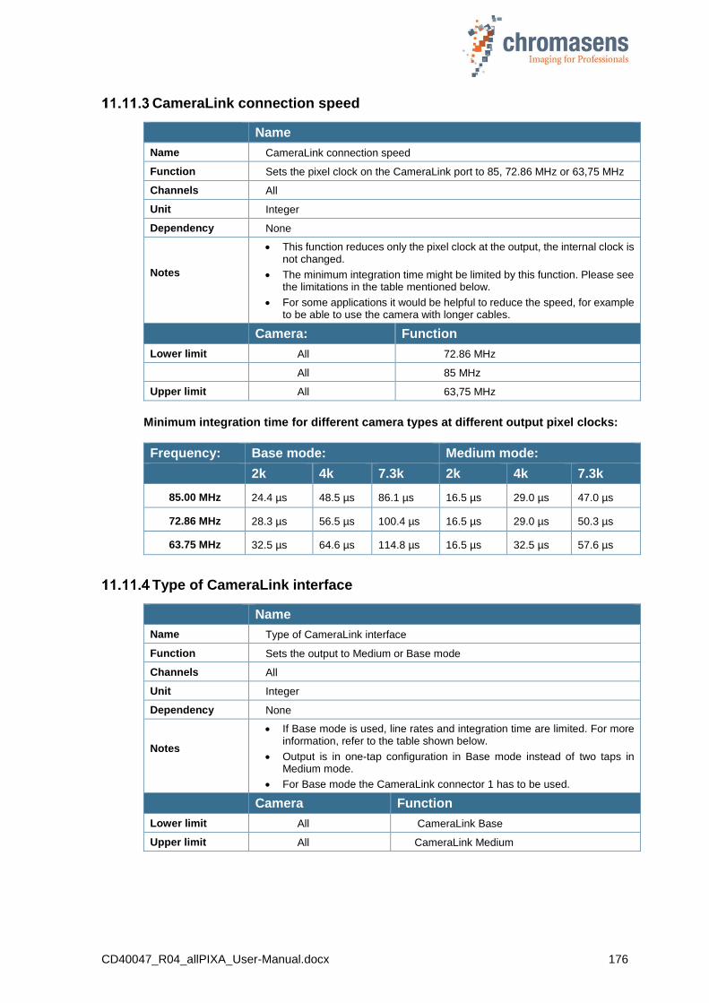
CD40047_R04_allPIXA_User-Manual.docx 176
CameraLink connection speed
Name
Name CameraLink connection speed
Function Sets the pixel clock on the CameraLink port to 85, 72.86 MHz or 63,75 MHz
Channels All
Unit Integer
Dependency None
Notes
This function reduces only the pixel clock at the output, the internal clock is not changed.
The minimum integration time might be limited by this function. Please see the limitations in the table mentioned below.
For some applications it would be helpful to reduce the speed, for example to be able to use the camera with longer cables.
Camera: Function
Lower limit All 72.86 MHz
All 85 MHz
Upper limit All 63,75 MHz
Minimum integration time for different camera types at different output pixel clocks:
Frequency: Base mode: Medium mode:
2k 4k 7.3k 2k 4k 7.3k
85.00 MHz 24.4 µs 48.5 µs 86.1 µs 16.5 µs 29.0 µs 47.0 µs
72.86 MHz 28.3 µs 56.5 µs 100.4 µs 16.5 µs 29.0 µs 50.3 µs
63.75 MHz 32.5 µs 64.6 µs 114.8 µs 16.5 µs 32.5 µs 57.6 µs
Type of CameraLink interface
Name
Name Type of CameraLink interface
Function Sets the output to Medium or Base mode
Channels All
Unit Integer
Dependency None
Notes
If Base mode is used, line rates and integration time are limited. For more information, refer to the table shown below.
Output is in one-tap configuration in Base mode instead of two taps in Medium mode.
For Base mode the CameraLink connector 1 has to be used.
Camera Function
Lower limit All CameraLink Base
Upper limit All CameraLink Medium
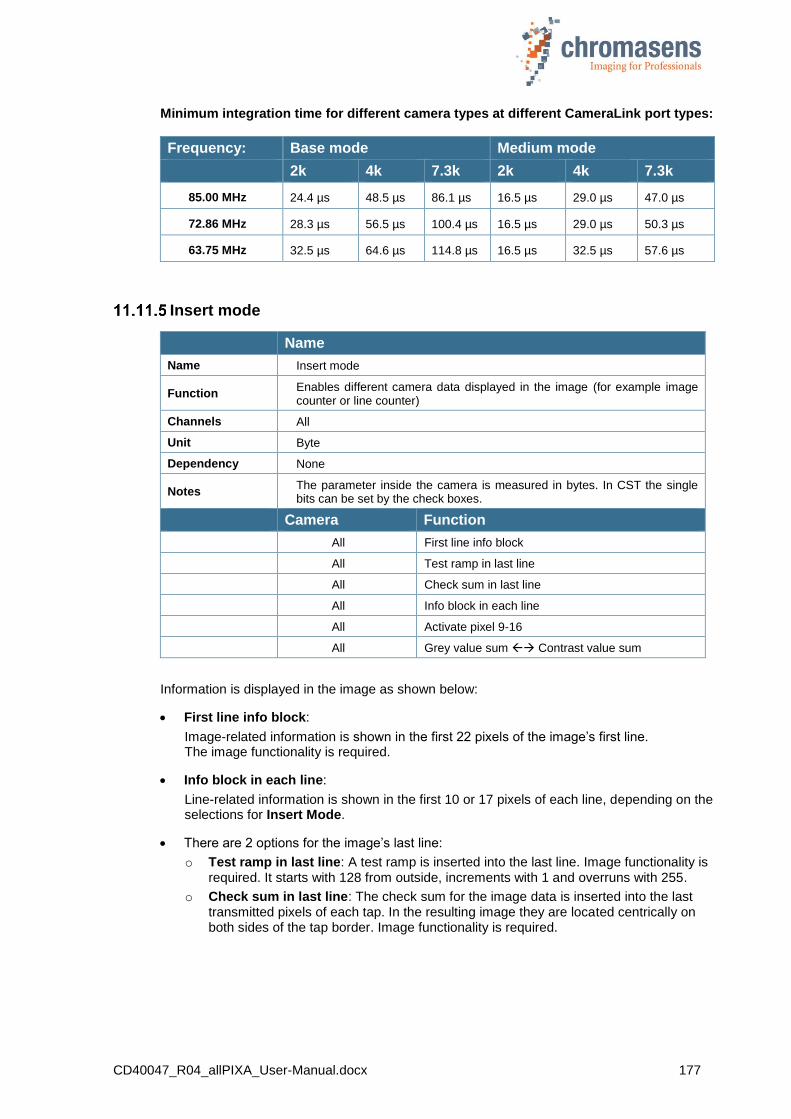
CD40047_R04_allPIXA_User-Manual.docx 177
Minimum integration time for different camera types at different CameraLink port types:
Frequency: Base mode Medium mode
2k 4k 7.3k 2k 4k 7.3k
85.00 MHz 24.4 µs 48.5 µs 86.1 µs 16.5 µs 29.0 µs 47.0 µs
72.86 MHz 28.3 µs 56.5 µs 100.4 µs 16.5 µs 29.0 µs 50.3 µs
63.75 MHz 32.5 µs 64.6 µs 114.8 µs 16.5 µs 32.5 µs 57.6 µs
Insert mode
Name
Name Insert mode
Function Enables different camera data displayed in the image (for example image counter or line counter)
Channels All
Unit Byte
Dependency None
Notes The parameter inside the camera is measured in bytes. In CST the single bits can be set by the check boxes.
Camera Function
All First line info block
All Test ramp in last line
All Check sum in last line
All Info block in each line
All Activate pixel 9-16
All Grey value sum Contrast value sum
Information is displayed in the image as shown below:
First line info block:
Image-related information is shown in the first 22 pixels of the image’s first line. The image functionality is required.
Info block in each line:
Line-related information is shown in the first 10 or 17 pixels of each line, depending on the selections for Insert Mode.
There are 2 options for the image’s last line:
o Test ramp in last line: A test ramp is inserted into the last line. Image functionality is required. It starts with 128 from outside, increments with 1 and overruns with 255.
o Check sum in last line: The check sum for the image data is inserted into the last transmitted pixels of each tap. In the resulting image they are located centrically on both sides of the tap border. Image functionality is required.
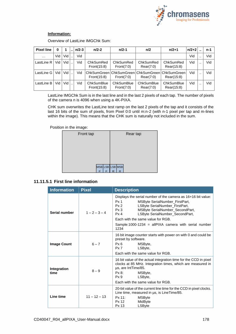
CD40047_R04_allPIXA_User-Manual.docx 178
Information:
Overview of LastLine IMGChk Sum:
Pixel line 0 1 .. n/2-3 n/2-2 n/2-1 n/2 n/2+1 n/2+2 .. n-1
… Vid Vid .. Vid Vid .. Vid
LastLine R Vid Vid .. Vid ChkSumRed Front(15:8)
ChkSumRed Front(7:0)
ChkSumRed Rear(7:0)
ChkSumRed Rear(15:8)
Vid .. Vid
LastLine G Vid Vid .. Vid ChkSumGreen Front(15:8)
ChkSumGreen Front(7:0)
ChkSumGreen Rear(7:0)
ChkSumGreen Rear(15:8)
Vid .. Vid
LastLine B Vid Vid .. Vid ChkSumBlue Front(15:8)
ChkSumBlue Front(7:0)
ChkSumBlue Rear(7:0)
ChkSumBlue Rear(15:8)
Vid .. Vid
LastLine IMGChk Sum is in the last line and in the last 2 pixels of each tap. The number of pixels of the camera n is 4096 when using a 4K-PIXA.
CHK sum overwrites the LastLine test ramp on the last 2 pixels of the tap and it consists of the last 16 bits of the sum of pixels, from Pixel 0:0 until m:n-2 (with n-1 pixel per tap and m-lines within the image). This means that the CHK sum is naturally not included in the sum.
11.11.5.1 First line information
Information Pixel Description
Serial number 1 – 2 – 3 – 4
Displays the serial number of the camera as 16+16 bit value:
Px 1 MSByte SerialNumber_FirstPart, Px 2 LSByte SerialNumber_FirstPart, Px 3 MSByte SerialNumber_SecondPart, Px 4 LSByte SerialNumber_SecondPart,
Each with the same value for RGB.
Sample:1000-1234 = allPIXA camera with serial number 1234
Image Count 6 – 7
16 bit image counter starts with power on with 0 and could be preset by software.
Px 6 MSByte, Px 7 LSByte,
Each with the same value for RGB.
Integration time
8 – 9
16 bit value of the actual integration time for the CCD in pixel clocks at 85 MHz. Integration times, which are measured in µs, are IntTime/85.
Px 8: MSByte, Px 9 LSByte,
Each with the same value for RGB.
Line time 11 – 12 – 13
20-bit value of the current line time for the CCD in pixel clocks. Line time, measured in µs, is LineTime/85.
Px 11: MSByte Px 12 MidByte Px 13 LSByte
Front tap Rear tap
LSB
F
MSB
F
LSB
R
MSB
R
Position in the image:

CD40047_R04_allPIXA_User-Manual.docx 179
Each with the same value for RGB.
Encoder clocks 14 – 15 – 16 – 17
32-bit counter starts with power on with 0 and overflows at 2^32.
Line trigger pulses (line trigger active) and encoder pulses (encoder active) counts depending on the selected mode; can be used as position information by a sequence of documents. Can be reset by software.
Px 14: MSByte Px 15 higher MidByte Px 16 lower MidByte Px 17 LSByte
Each with the same value for RGB.
Error register 18 In case of any default, it will be inserted here.
Time stamp 19 – 20 – 21
„Real time clock”. Output is in a 16.8b seconds value. TimeStamp (23:8) states the seconds when the power is on or in case of reset. TimeStamp (7:0) issues the decimal places in a multiple of 4 milliseconds. (0…249)
Sample: TimeStamp = 0x123456
0x1234 = 4660 seconds since start = 1h, 17min, 40 seconds
0x56 = 86 *4= 344 ms.
Px 19 MSByte Px 20 MidByte Px 21 LSByte
Each with the same value for RGB.
Markers 0 – 5 – 10 – 22
It is used for marking the info block with red pixels.
Red xFF Blue x00 Green x00
Overview off the info block „First line info block“:
Pixel 0 1 2 3 4 5 6 7 8 9 10 11 12 13 14 15 16 17 18 19 20 21 22
Lin
e 0
Se
ria
l n
o.
Ima
ge
co
unt
Inte
gra
tion
tim
e
Lin
e tim
e
En
co
de
r
clo
cks
Err
or
reg
.
Tim
e s
tam
p
11.11.5.2 Each line information
Information Pixel Channel Description
Error register 1 R In case of any default, it is inserted here.
Line Count 1 G/B 16 bit line count since image start
Speed too high 2 R (7)
The highest bit has the value of “Speed2High” (the line time decreases the specified integration time). Now, the camera is in free-running line mode (only in Encoder/Line trigger mode if the speed becomes too high).
Line time 2 R/G/B
20-bit value of the actual line time for the CCD in pixel clocks. The line time, measured in µs, is LineTime/85.
Red MSByte (3:0), Bits (6:4) are zero Green MidByte Blue LSByte
Encoder clock 3 R/G/B 24-bit counter starts at power on with 0 and overflows at 2^24
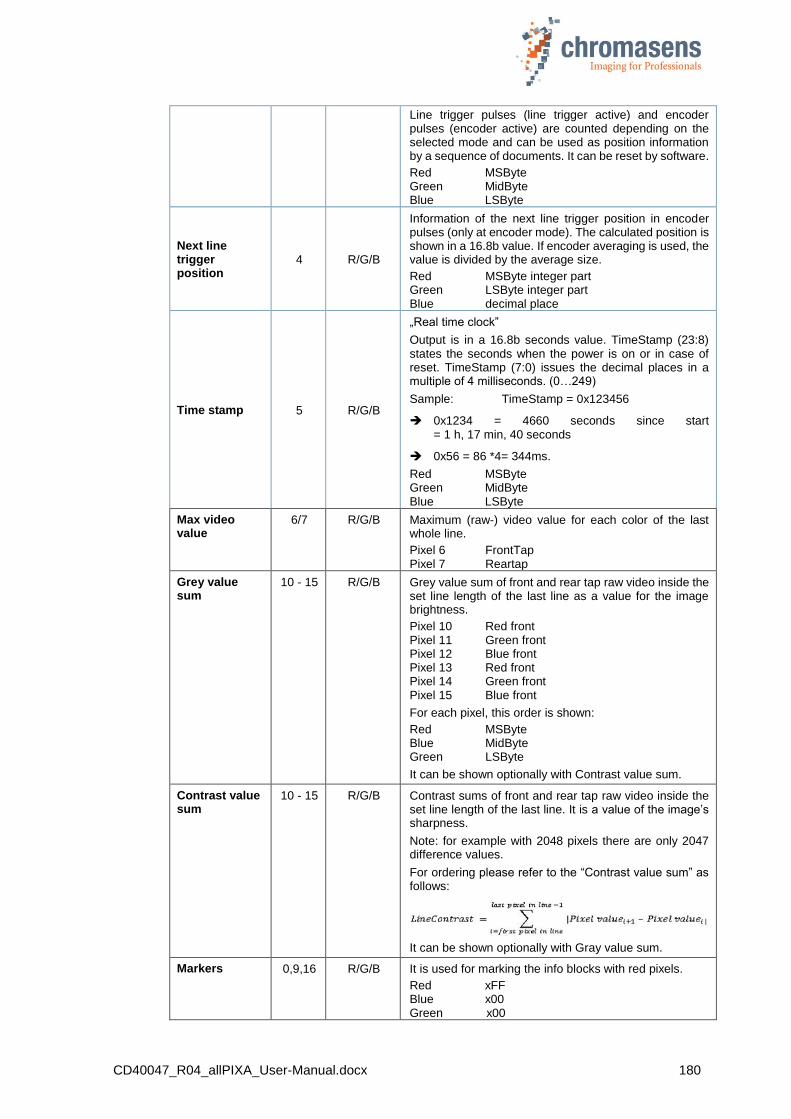
CD40047_R04_allPIXA_User-Manual.docx 180
Line trigger pulses (line trigger active) and encoder pulses (encoder active) are counted depending on the selected mode and can be used as position information by a sequence of documents. It can be reset by software.
Red MSByte Green MidByte Blue LSByte
Next line trigger position
4 R/G/B
Information of the next line trigger position in encoder pulses (only at encoder mode). The calculated position is shown in a 16.8b value. If encoder averaging is used, the value is divided by the average size.
Red MSByte integer part Green LSByte integer part Blue decimal place
Time stamp 5 R/G/B
„Real time clock”
Output is in a 16.8b seconds value. TimeStamp (23:8) states the seconds when the power is on or in case of reset. TimeStamp (7:0) issues the decimal places in a multiple of 4 milliseconds. (0…249)
Sample: TimeStamp = 0x123456
0x1234 = 4660 seconds since start = 1 h, 17 min, 40 seconds
0x56 = 86 *4= 344ms.
Red MSByte Green MidByte Blue LSByte
Max video value
6/7 R/G/B Maximum (raw-) video value for each color of the last whole line.
Pixel 6 FrontTap Pixel 7 Reartap
Grey value sum
10 - 15 R/G/B Grey value sum of front and rear tap raw video inside the set line length of the last line as a value for the image brightness.
Pixel 10 Red front Pixel 11 Green front Pixel 12 Blue front Pixel 13 Red front Pixel 14 Green front Pixel 15 Blue front
For each pixel, this order is shown:
Red MSByte Blue MidByte Green LSByte
It can be shown optionally with Contrast value sum.
Contrast value sum
10 - 15 R/G/B Contrast sums of front and rear tap raw video inside the set line length of the last line. It is a value of the image’s sharpness.
Note: for example with 2048 pixels there are only 2047 difference values.
For ordering please refer to the “Contrast value sum” as follows:
It can be shown optionally with Gray value sum.
Markers 0,9,16 R/G/B It is used for marking the info blocks with red pixels.
Red xFF Blue x00 Green x00
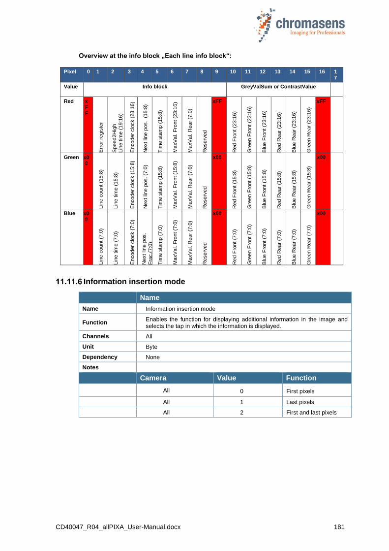
CD40047_R04_allPIXA_User-Manual.docx 181
Overview at the info block „Each line info block“:
Pixel 0 1 2 3 4 5 6 7 8 9 10 11 12 13 14 15 16 17
Value Info block GreyValSum or ContrastValue
Red xFF
Err
or
regis
ter
Speed2H
igh
Lin
e t
ime
(19:1
6)
Encoder
clo
ck (
23:1
6)
Next lin
e p
os. (
15:8
)
Tim
e s
tam
p (
15:8
)
Ma
xV
al. F
ront (2
3:1
6)
Ma
xV
al. R
ear
(7:0
)
Reserv
ed
xFF
Red F
ront
(23:1
6)
Gre
en F
ront
(23:1
6)
Blu
e F
ront (2
3:1
6)
Red R
ear
(23:1
6)
Blu
e R
ear
(23:1
6)
Gre
en R
ear
(23:1
6)
xFF
Green x00
Lin
e c
ount (1
5:8
)
Lin
e t
ime
(15:8
)
Encoder
clo
ck (
15:8
)
Next lin
e p
os. (7
:0)
Tim
e s
tam
p (
15:8
)
Ma
xV
al. F
ront (1
5:8
)
Ma
xV
al. R
ear
(7:0
)
Reserv
ed
x00
Red F
ront
(15:8
)
Gre
en F
ront
(15:8
)
Blu
e F
ront (1
5:8
)
Red R
ear
(15:8
)
Blu
e R
ear
(15:8
)
Gre
en R
ear
(15:8
)
x00
Blue x00
Lin
e c
ount (7
:0)
Lin
e t
ime
(7:0
)
Encoder
clo
ck (
7:0
)
Next lin
e p
os.
Fra
c,(
7:0
)
Tim
e s
tam
p (
7:0
)
Ma
xV
al. F
ront (7
:0)
Ma
xV
al. R
ear
(7:0
)
Reserv
ed
x00
Red F
ront
(7:0
)
Gre
en F
ront
(7:0
)
Blu
e F
ront (7
:0)
Red R
ear
(7:0
)
Blu
e R
ear
(7:0
)
Gre
en R
ear
(7:0
)
x00
Information insertion mode
Name
Name Information insertion mode
Function Enables the function for displaying additional information in the image and selects the tap in which the information is displayed.
Channels All
Unit Byte
Dependency None
Notes
Camera Value Function
All 0 First pixels
All 1 Last pixels
All 2 First and last pixels
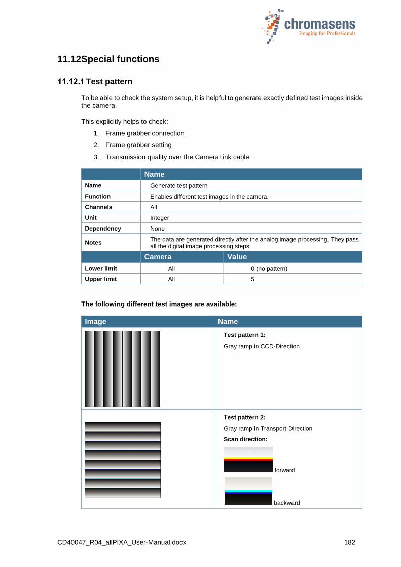
CD40047_R04_allPIXA_User-Manual.docx 182
11.12 Special functions
Test pattern
To be able to check the system setup, it is helpful to generate exactly defined test images inside the camera.
This explicitly helps to check:
1. Frame grabber connection
2. Frame grabber setting
3. Transmission quality over the CameraLink cable
Name
Name Generate test pattern
Function Enables different test images in the camera.
Channels All
Unit Integer
Dependency None
Notes The data are generated directly after the analog image processing. They pass all the digital image processing steps
Camera Value
Lower limit All 0 (no pattern)
Upper limit All 5
The following different test images are available:
Image Name
Test pattern 1:
Gray ramp in CCD-Direction
Test pattern 2:
Gray ramp in Transport-Direction
Scan direction:
forward
backward

CD40047_R04_allPIXA_User-Manual.docx 183
Test pattern 3:
Red: X-Ramp
Green: XY-Ramp
Blue: Y-Ramp
Test pattern 4:
Sequence of 4 toggling images; 3 test patterns with parameter Test pattern level and one live image
Test pattern 5:
Grey value with parameter Test pattern level
Set Test pattern level
Name
Name Set Test pattern level
Function Sets the video level for some test images
Channels All
Unit Integer
Linear
Dependency Only with test image 3 to 5
Notes Refers to 10-bit image data
Camera Value
Lower limit All 0
Upper limit All 1023

CD40047_R04_allPIXA_User-Manual.docx 184
11.13 Register edit
All registers can be written directly on the camera.
There are two possibilities to directly modify the register:
Permanent modification:
Values entered by the user are stored in the setting. If the setting is burned, they are available after the camera is restarted or after the setting has been loaded.
You can find this function in CST at Camera settings > Special functions > Register edit. There are 4 places for saving register edits directly to a setting.
Non-permanent modification:
Changes are transferred to the camera, but they are not stored permanently. If the camera is restarted or a setting is reloaded, the changes get lost. You can find this function in CST at the command Register edit of the Advanced menu.
It is possible to damage the function of the camera itself by using this function.
Therefore this is function is only available if User level has been set to Guru.
For more information, see section 9.14 “Setting the user level in CST”.
11.14 Camera information
Camera serial number
Note All allPIXA wave cameras have an individual serial number. For any support, provide the serial number of the camera.
Name
Name Camera serial number Read only
Function Returns the camera type and serial number of the camera
Channels All
Unit Two integers
Dependency None
Notes The first value is the camera type (10000 for the allPIXA camera). The second value is the serial number
Camera Value camera type Value serial number
Lower limit All 10000 0
Upper limit All 10000 65535
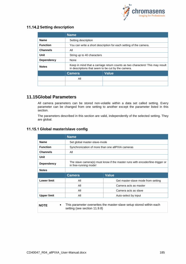
CD40047_R04_allPIXA_User-Manual.docx 185
Setting description
Name
Name Setting description
Function You can write a short description for each setting of the camera.
Channels All
Unit String up to 40 characters
Dependency None
Notes Keep in mind that a carriage return counts as two characters! This may result in descriptions that seem to be cut by the camera.
Camera Value
All
11.15 Global Parameters
All camera parameters can be stored non-volatile within a data set called setting. Every parameter can be changed from one setting to another except the parameter listed in this section.
The parameters described in this section are valid, independently of the selected setting. They are global.
Global master/slave config
Name
Name Set global master-slave-mode
Function Synchronization of more than one allPIXA cameras
Channels All
Unit
Dependency The slave camera(s) must know if the master runs with encoder/line-trigger or in free-running mode!
Notes
Camera Value
Lower limit All Get master-slave mode from setting
All Camera acts as master
All Camera acts as slave
Upper limit All Auto-select by input
NOTE This parameter overwrites the master-slave setup stored within each setting (see section 11.9.8)

CD40047_R04_allPIXA_User-Manual.docx 186
Tracing
For test and debugging purposes, the camera writes process data to an internal logging memory. Which data are logged, can be selected by selecting check boxes on the Tracing page.
For more information, ask the Chromasens support.
E-Mail: [email protected]
NOTE Logging of process data reduces performance of the internal microcontroller. Therefore the internal trace should only be activated for testing. All tracing should be deactivated in real production mode of the camera.
11.16 Line trigger and encoder setup (Line synchronisation)
NOTE I Due to internal timing limitations there is a small delay in the start of the integration time after the line trigger and this delay might jitter. Therefore, a pulsed illumination which is synchronous to the trigger signal might cause problems in image quality.
NOTE II If the camera is used in the “Triggered Frame Scan” with active LineTrigger or encoder, the linesync (Encoder or LineTrigger) has to fit some pulses before light barrier input.
Enable encoder
Name
Name Enable encoder
Function
Enables the line trigger or encoder mode in the camera and the main selection between internal and external line trigger.
Without encoder, camera speed is defined by the values of Integration time and optionally by Line period time. If encoder is enabled, camera speed if
defined by an external line trigger or by encoder pulses.
Channels All
Unit Bool
Dependency None
Notes If you use this mode, the external ports must be connected with the internal function using the IO Configurator of CST.
Camera Function
Lower limit All Off / Internal
Upper limit All On / external

CD40047_R04_allPIXA_User-Manual.docx 187
Synchronization mode
Name
Name Synchronization mode
Function Selects the mode Encoder or Line trigger mode.
Channels All
Unit Integer
Dependency Only available if Enable Encoder is active.
Notes If you use this mode, the external ports must be connected with the internal function using the IO Configurator of CST.
Camera: Values:
All Encoder (Continue update)
All Line trigger mode (Const. int. time)
The following two modes are available:
Line trigger mode:
With the line trigger, the camera sends one line per pulse:
Encoder mode:
The camera measures the distance of the signals and sends lines with the requested resolution. An internal line trigger is generated. The desired transport and encoder resolution must be specified in CST.
NOTE Minimum pulse duration of the line trigger or encoder has to be 5 pulses of the internal pixel clock of 85 MHz. Minimum pulse duration is 60ns. Otherwise, the pulse might be ignored due to debouncing within the camera.
Minimum speed with encoder mode is:
V,min = mm/Encoder pulse 0,789s
Example for the required minimum speed with encoder mode:
Encoder has 12,5 pulses per mm
1 Encoder pulse is 1/12,5mm = 0,08mm
V, min = 0,08mm/0,789s = 0,101mm/s
Int. time Int. time Int. time
Line trigger

CD40047_R04_allPIXA_User-Manual.docx 188
Encoder channels
Name
Name Encoder channels
Function Sets the mode according to the edges of the encoder will be taken for speed measurement.
Channels All
Unit Integer
Dependency Only available if Encoder is selected at Synchronization mode
Notes If you use this mode, the external ports must be connected with the internal function using the IO Configurator of CST.
Camera Value Function
Lower limit All 0 One Channel full step
All 1 One Channel encoder
Upper limit All 2 2 Channel encoder
The following three modes are available:
0. One Channel full step (1 edge per step):
1. One Channel encoder (2 edges per step):
2. Two Channel encoder (4 edges per step):
NOTE Best results are reached with encoder mode 0 and without encoder averaging. This mode avoids errors due to tolerances in the duty factor of the pulses.
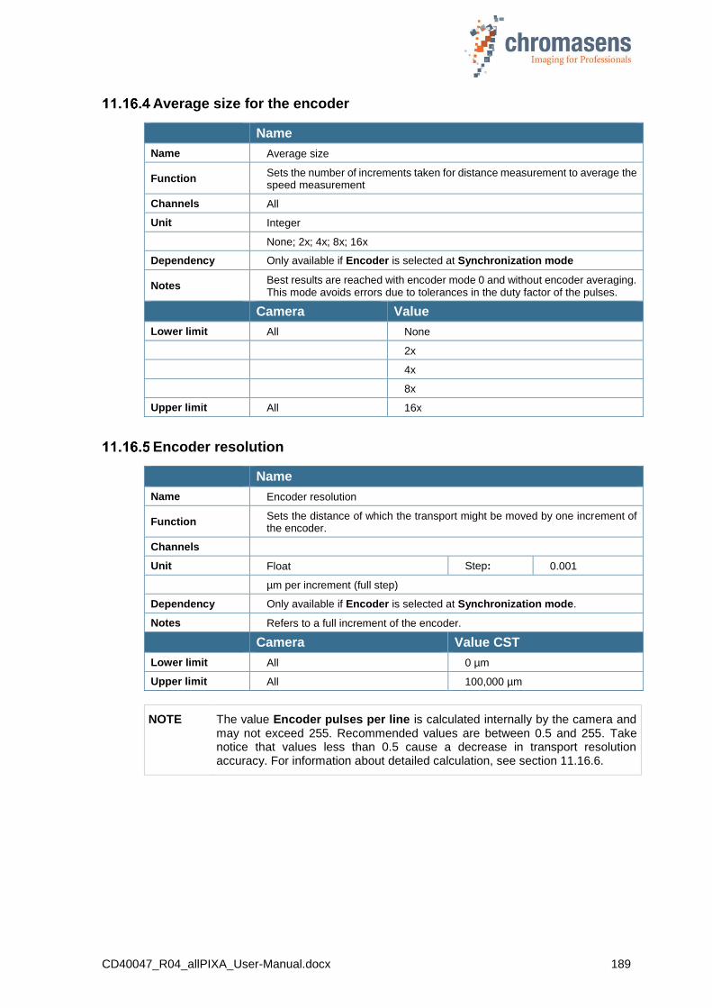
CD40047_R04_allPIXA_User-Manual.docx 189
Average size for the encoder
Name
Name Average size
Function Sets the number of increments taken for distance measurement to average the speed measurement
Channels All
Unit Integer
None; 2x; 4x; 8x; 16x
Dependency Only available if Encoder is selected at Synchronization mode
Notes Best results are reached with encoder mode 0 and without encoder averaging. This mode avoids errors due to tolerances in the duty factor of the pulses.
Camera Value
Lower limit All None
2x
4x
8x
Upper limit All 16x
Encoder resolution
Name
Name Encoder resolution
Function Sets the distance of which the transport might be moved by one increment of the encoder.
Channels
Unit Float Step: 0.001
µm per increment (full step)
Dependency Only available if Encoder is selected at Synchronization mode.
Notes Refers to a full increment of the encoder.
Camera Value CST
Lower limit All 0 µm
Upper limit All 100,000 µm
NOTE The value Encoder pulses per line is calculated internally by the camera and may not exceed 255. Recommended values are between 0.5 and 255. Take notice that values less than 0.5 cause a decrease in transport resolution accuracy. For information about detailed calculation, see section 11.16.6.
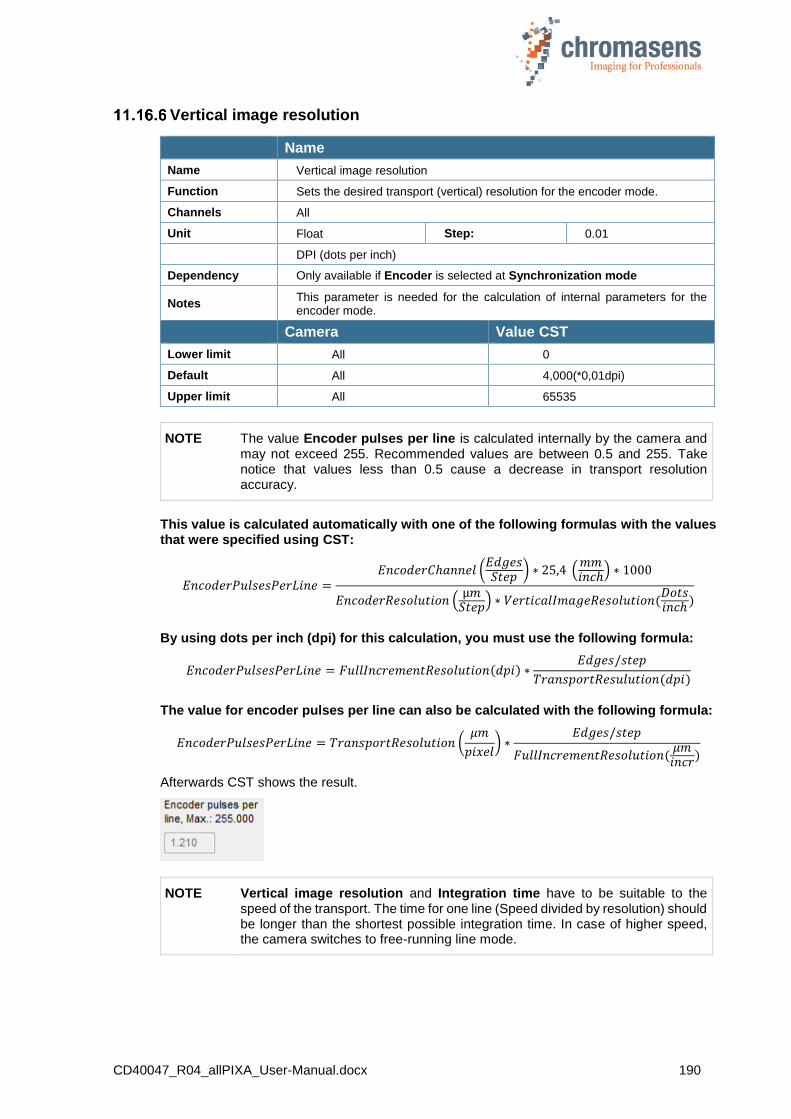
CD40047_R04_allPIXA_User-Manual.docx 190
Vertical image resolution
Name
Name Vertical image resolution
Function Sets the desired transport (vertical) resolution for the encoder mode.
Channels All
Unit Float Step: 0.01
DPI (dots per inch)
Dependency Only available if Encoder is selected at Synchronization mode
Notes This parameter is needed for the calculation of internal parameters for the encoder mode.
Camera Value CST
Lower limit All 0
Default All 4,000(*0,01dpi)
Upper limit All 65535
NOTE The value Encoder pulses per line is calculated internally by the camera and may not exceed 255. Recommended values are between 0.5 and 255. Take notice that values less than 0.5 cause a decrease in transport resolution accuracy.
This value is calculated automatically with one of the following formulas with the values that were specified using CST:
𝐸𝑛𝑐𝑜𝑑𝑒𝑟𝑃𝑢𝑙𝑠𝑒𝑠𝑃𝑒𝑟𝐿𝑖𝑛𝑒 =𝐸𝑛𝑐𝑜𝑑𝑒𝑟𝐶ℎ𝑎𝑛𝑛𝑒𝑙 (
𝐸𝑑𝑔𝑒𝑠𝑆𝑡𝑒𝑝
) ∗ 25,4 (𝑚𝑚𝑖𝑛𝑐ℎ
) ∗ 1000
𝐸𝑛𝑐𝑜𝑑𝑒𝑟𝑅𝑒𝑠𝑜𝑙𝑢𝑡𝑖𝑜𝑛 (µ𝑚
𝑆𝑡𝑒𝑝) ∗ 𝑉𝑒𝑟𝑡𝑖𝑐𝑎𝑙𝐼𝑚𝑎𝑔𝑒𝑅𝑒𝑠𝑜𝑙𝑢𝑡𝑖𝑜𝑛(
𝐷𝑜𝑡𝑠𝑖𝑛𝑐ℎ
)
By using dots per inch (dpi) for this calculation, you must use the following formula:
𝐸𝑛𝑐𝑜𝑑𝑒𝑟𝑃𝑢𝑙𝑠𝑒𝑠𝑃𝑒𝑟𝐿𝑖𝑛𝑒 = 𝐹𝑢𝑙𝑙𝐼𝑛𝑐𝑟𝑒𝑚𝑒𝑛𝑡𝑅𝑒𝑠𝑜𝑙𝑢𝑡𝑖𝑜𝑛(𝑑𝑝𝑖) ∗𝐸𝑑𝑔𝑒𝑠/𝑠𝑡𝑒𝑝
𝑇𝑟𝑎𝑛𝑠𝑝𝑜𝑟𝑡𝑅𝑒𝑠𝑢𝑙𝑢𝑡𝑖𝑜𝑛(𝑑𝑝𝑖)
The value for encoder pulses per line can also be calculated with the following formula:
𝐸𝑛𝑐𝑜𝑑𝑒𝑟𝑃𝑢𝑙𝑠𝑒𝑠𝑃𝑒𝑟𝐿𝑖𝑛𝑒 = 𝑇𝑟𝑎𝑛𝑠𝑝𝑜𝑟𝑡𝑅𝑒𝑠𝑜𝑙𝑢𝑡𝑖𝑜𝑛 (𝜇𝑚
𝑝𝑖𝑥𝑒𝑙) ∗
𝐸𝑑𝑔𝑒𝑠/𝑠𝑡𝑒𝑝
𝐹𝑢𝑙𝑙𝐼𝑛𝑐𝑟𝑒𝑚𝑒𝑛𝑡𝑅𝑒𝑠𝑜𝑙𝑢𝑡𝑖𝑜𝑛(𝜇𝑚𝑖𝑛𝑐𝑟
)
Afterwards CST shows the result.
NOTE Vertical image resolution and Integration time have to be suitable to the speed of the transport. The time for one line (Speed divided by resolution) should be longer than the shortest possible integration time. In case of higher speed, the camera switches to free-running line mode.
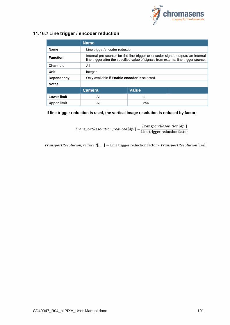
CD40047_R04_allPIXA_User-Manual.docx 191
Line trigger / encoder reduction
Name
Name Line trigger/encoder reduction
Function Internal pre-counter for the line trigger or encoder signal, outputs an internal line trigger after the specified value of signals from external line trigger source.
Channels All
Unit integer
Dependency Only available if Enable encoder is selected.
Notes
Camera Value
Lower limit All 1
Upper limit All 256
If line trigger reduction is used, the vertical image resolution is reduced by factor:
𝑇𝑟𝑎𝑛𝑠𝑝𝑜𝑟𝑡𝑅𝑒𝑠𝑜𝑙𝑢𝑡𝑖𝑜𝑛, 𝑟𝑒𝑑𝑢𝑐𝑒𝑑[𝑑𝑝𝑖] =𝑇𝑟𝑎𝑛𝑠𝑝𝑜𝑟𝑡𝑅𝑒𝑠𝑜𝑙𝑢𝑡𝑖𝑜𝑛[𝑑𝑝𝑖]
Line trigger reduction factor
𝑇𝑟𝑎𝑛𝑠𝑝𝑜𝑟𝑡𝑅𝑒𝑠𝑜𝑙𝑢𝑡𝑖𝑜𝑛, 𝑟𝑒𝑑𝑢𝑐𝑒𝑑[µ𝑚] = Line trigger reduction factor ∗ 𝑇𝑟𝑎𝑛𝑠𝑝𝑜𝑟𝑡𝑅𝑒𝑠𝑜𝑙𝑢𝑡𝑖𝑜𝑛[µ𝑚]
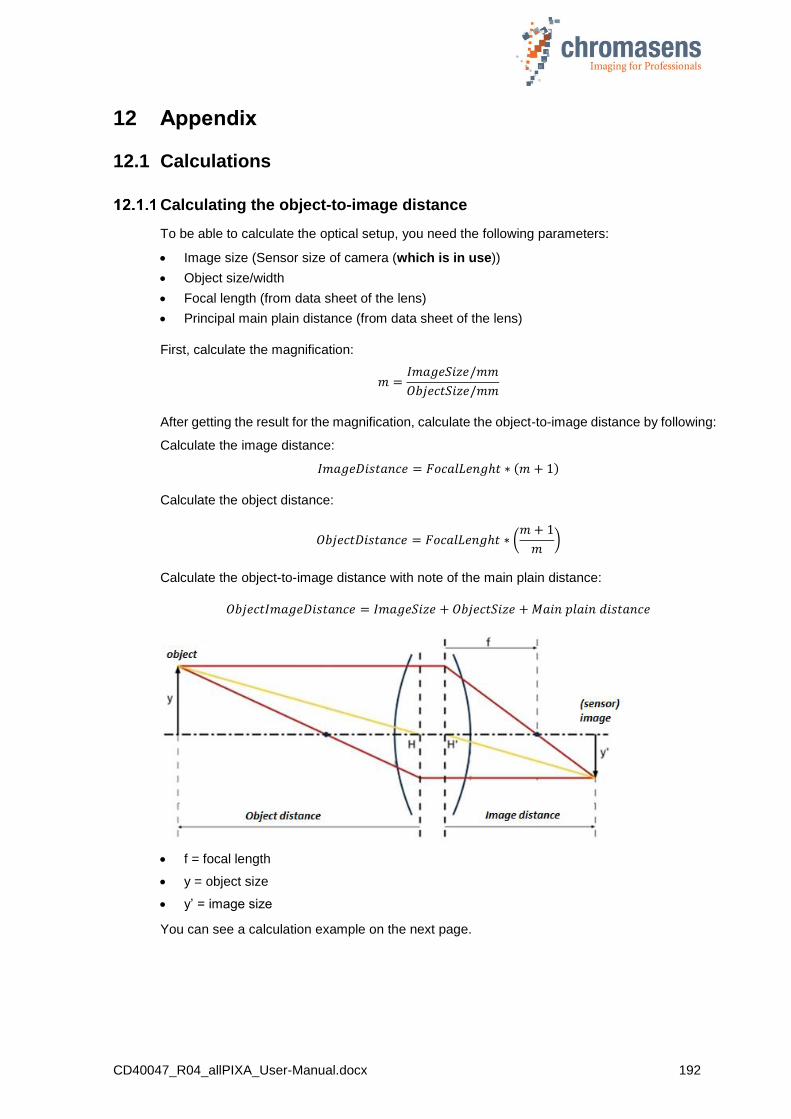
CD40047_R04_allPIXA_User-Manual.docx 192
12 Appendix
12.1 Calculations
Calculating the object-to-image distance
To be able to calculate the optical setup, you need the following parameters:
Image size (Sensor size of camera (which is in use))
Object size/width
Focal length (from data sheet of the lens)
Principal main plain distance (from data sheet of the lens)
First, calculate the magnification:
𝑚 =𝐼𝑚𝑎𝑔𝑒𝑆𝑖𝑧𝑒/𝑚𝑚
𝑂𝑏𝑗𝑒𝑐𝑡𝑆𝑖𝑧𝑒/𝑚𝑚
After getting the result for the magnification, calculate the object-to-image distance by following:
Calculate the image distance:
𝐼𝑚𝑎𝑔𝑒𝐷𝑖𝑠𝑡𝑎𝑛𝑐𝑒 = 𝐹𝑜𝑐𝑎𝑙𝐿𝑒𝑛𝑔ℎ𝑡 ∗ (𝑚 + 1)
Calculate the object distance:
𝑂𝑏𝑗𝑒𝑐𝑡𝐷𝑖𝑠𝑡𝑎𝑛𝑐𝑒 = 𝐹𝑜𝑐𝑎𝑙𝐿𝑒𝑛𝑔ℎ𝑡 ∗ (𝑚 + 1
𝑚)
Calculate the object-to-image distance with note of the main plain distance:
𝑂𝑏𝑗𝑒𝑐𝑡𝐼𝑚𝑎𝑔𝑒𝐷𝑖𝑠𝑡𝑎𝑛𝑐𝑒 = 𝐼𝑚𝑎𝑔𝑒𝑆𝑖𝑧𝑒 + 𝑂𝑏𝑗𝑒𝑐𝑡𝑆𝑖𝑧𝑒 + 𝑀𝑎𝑖𝑛 𝑝𝑙𝑎𝑖𝑛 𝑑𝑖𝑠𝑡𝑎𝑛𝑐𝑒
f = focal length
y = object size
y’ = image size
You can see a calculation example on the next page.
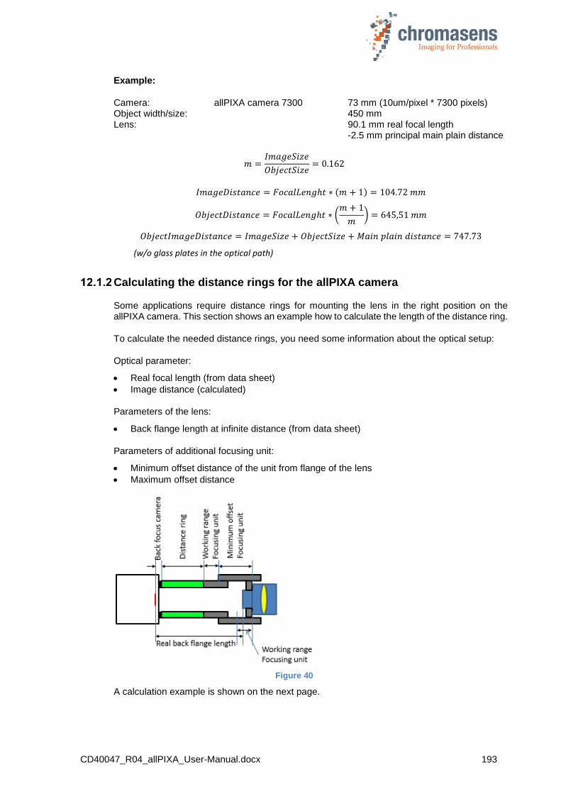
CD40047_R04_allPIXA_User-Manual.docx 193
Example:
Camera: allPIXA camera 7300 73 mm (10um/pixel * 7300 pixels) Object width/size: 450 mm Lens: 90.1 mm real focal length -2.5 mm principal main plain distance
𝑚 =𝐼𝑚𝑎𝑔𝑒𝑆𝑖𝑧𝑒
𝑂𝑏𝑗𝑒𝑐𝑡𝑆𝑖𝑧𝑒= 0.162
𝐼𝑚𝑎𝑔𝑒𝐷𝑖𝑠𝑡𝑎𝑛𝑐𝑒 = 𝐹𝑜𝑐𝑎𝑙𝐿𝑒𝑛𝑔ℎ𝑡 ∗ (𝑚 + 1) = 104.72 𝑚𝑚
𝑂𝑏𝑗𝑒𝑐𝑡𝐷𝑖𝑠𝑡𝑎𝑛𝑐𝑒 = 𝐹𝑜𝑐𝑎𝑙𝐿𝑒𝑛𝑔ℎ𝑡 ∗ (𝑚 + 1
𝑚) = 645,51 𝑚𝑚
𝑂𝑏𝑗𝑒𝑐𝑡𝐼𝑚𝑎𝑔𝑒𝐷𝑖𝑠𝑡𝑎𝑛𝑐𝑒 = 𝐼𝑚𝑎𝑔𝑒𝑆𝑖𝑧𝑒 + 𝑂𝑏𝑗𝑒𝑐𝑡𝑆𝑖𝑧𝑒 + 𝑀𝑎𝑖𝑛 𝑝𝑙𝑎𝑖𝑛 𝑑𝑖𝑠𝑡𝑎𝑛𝑐𝑒 = 747.73
(w/o glass plates in the optical path)
Calculating the distance rings for the allPIXA camera
Some applications require distance rings for mounting the lens in the right position on the allPIXA camera. This section shows an example how to calculate the length of the distance ring.
To calculate the needed distance rings, you need some information about the optical setup:
Optical parameter:
Real focal length (from data sheet)
Image distance (calculated)
Parameters of the lens:
Back flange length at infinite distance (from data sheet)
Parameters of additional focusing unit:
Minimum offset distance of the unit from flange of the lens
Maximum offset distance
Figure 40
A calculation example is shown on the next page.
CD40047_R04_allPIXA_User-Manual.docx 194
Example:
Camera: allPIXA camera 7300 Lens: Linos Apo Rodagon 90 mm
90.1 mm real focal length 93.5 mm flange length@infinite
Focusing unit: Modular Fokus Minimum offset 20 mm Maxium offset 45 mm Object width/size: 450 mm
1. Calculating image distance:
a. Calculating the magnification:
𝑚 =𝐼𝑚𝑎𝑔𝑒𝑆𝑖𝑧𝑒/𝑚𝑚
𝑂𝑏𝑗𝑒𝑐𝑡𝑆𝑖𝑧𝑒/𝑚𝑚
b. Calculating the image distance:
𝐼𝑚𝑎𝑔𝑒𝐷𝑖𝑠𝑡𝑎𝑛𝑐𝑒 = 𝐹𝑜𝑐𝑎𝑙𝐿𝑒𝑛𝑔ℎ𝑡 ∗ (𝑚 + 1) Result is: 104,72 mm
2. Calculating the difference between image distance@infinite and flange length@infinite: Image distance@infinite converged to focal length: 90.1 mm Difference: 93.5 mm -90.1 mm = 3.4 mm
3. Calculating flange distance at working point: Flange distance@working point: 104.72 mm + 3.4 mm =108.12 mm
4. Calculating the sum of the distances: Real flange distance: + 108.12 Back focus of the allPIXA camera: - 17.526 mm (C-Mount) Minimum offset focusing unit: - 20.0 mm Sum: = 70.954 mm Therefore, we use a distance ring of 60.0 mm. This covers flange distances from 97.526 mm up to 122.56 mm.
Calculating the integration time
The relationship between the line frequency and the integration time is as follows:
𝐼𝑛𝑡𝑒𝑔𝑟𝑎𝑡𝑖𝑜𝑛𝑇𝑖𝑚𝑒/𝑠𝑒𝑐. =1
𝐿𝑖𝑛𝑒𝐹𝑟𝑒𝑢𝑞𝑢𝑒𝑛𝑐𝑦/𝐻𝑧
For the calculation of the integration time the following parameters are necessary:
o Maximum or nominal speed of the transport (mm/s)
o Desired transport resolution (mm/pixel or dpi)
Calculate the integration time with the formula as follows:
𝑰𝒏𝒕𝒆𝒈𝒓𝒂𝒕𝒊𝒐𝒏𝑻𝒊𝒎𝒆 =𝑻𝒓𝒂𝒏𝒔𝒑𝒐𝒓𝒕𝑹𝒆𝒔𝒐𝒍𝒖𝒕𝒊𝒐𝒏 (
𝒎𝒎𝒑𝒊𝒙𝒆𝒍
)
𝑵𝒐𝒎𝒊𝒏𝒂𝒍𝑺𝒑𝒆𝒆𝒅 (𝒎𝒎
𝒔 )
Note: If the transport resolution is stated in dpi and the speed in metric values, the values have to be converted (1 inch= 25,4 mm).

CD40047_R04_allPIXA_User-Manual.docx 195
Communication to the camera via the Chromasens API
Figure 41: Chromasens API
The Chromasens API provides a set of functions for communication with the allPIXA camera.
With these functions, connection to the camera can be established via CameraLink or serial RS232 connection.
Internal working parameters of the camera can be read and modified.
Convenience functions for calibration of the camera are provided.
Calibration of the camera can be performed to adapt to current illumination conditions.
Functions for low-level communication are also implemented in the Chromasens API.
A detailed description, example code and the necessary DLLs for integration are provided in the CSAPI package, which can be downloaded from the allPIXA download area on our website.
Chromasens API
Customer application
allPIXA
Configuration data
CD40047_R04_allPIXA_User-Manual.docx 196
13 Maintenance and cleaning of the allPIXA camera
During operation of the device, particles such as dust etc. may be settled on the optical components (lens) of the camera. These negative deposits affect the optical image and the function of the camera.
Chromasens recommends regular inspection and cleaning. The cleaning intervals depend on the actual operating and ambient conditions (for example dust-laden atmosphere).
13.1 Cleaning intervals
Cleaning intervals depend on the environment. Regular inspection and cleaning intervals must be specified depending on the degree of soiling.
13.2 Cleaning process
Body of the allPIXA camera heats up during operation.
Before cleaning, you have to switch off the device. Always allow hot surfaces to cool down before cleaning the device.
The device works with electric power. Before cleaning the device, make sure that the device is disconnected from the power supply.
All surfaces requiring cleaning can be wiped with a soft, lint-free cloth which can be moistened with Isopropanol.
Never use any other liquid or cleaning agent than those stated in this manual.
Never use hard or sharp tools for cleaning the device.
Inspect the device to ensure that cleaning was effective and repeat, if necessary.
If it is not possible to clean a component due to irremovable contamination, it must be replaced.

CD40047_R04_allPIXA_User-Manual.docx 197
14 Service and repair
The device works with electric power. Before cleaning the device, make sure that the device is disconnected from the power supply.
Body of the allPIXA wave camera heats up during operation.
Before you work on the device, you must switch off the device. Always allow hot surfaces to cool down before cleaning the device.
Do not perform any repairs at the device by yourself, except, if you need to maintain, exchange spare parts or adjust scanning position.
The manufacturer of the superior system is responsible for all repairs and service matters, repair activities as well as exceeding the exchange of spare parts have to be done by the manufacturer of the superior system which is either the device manufacturer Chromasens GmbH or the exclusively authorized partner.
Keep the original package for a possible return of the device because the device has to be returned in the original package to avoid damages.
14.1 Return address for repair
Please contact the Chromasens service first before you return the camera.
Please ask for an RMA number before you return the camera to the manufacturer.
Chromasens GmbH Max-Stromeyer-Straße 116 D-78467 Konstanz Germany
Phone: +49 (0) 7531 - 876-0 Fax: +49 (0) 7531 - 876-303
E-Mail: [email protected] Internet: www.chromasens.de
14.2 Disposal
The device consists of different kinds of material and for its disposal the materials have to be separated according to the local regulations. The material has to be disposed properly to avoid and to minimize any environmental or human impact.
CD40047_R04_allPIXA_User-Manual.docx 198
15 EC conformity declaration
CD40047_R04_allPIXA_User-Manual.docx 199
Chromasens GmbH
Max-Stromeyer-Straße 116 Phone: +49 7531 876-0 www.chromasens.de
78467 Konstanz Fax: +49 7531 876-303 [email protected]
Germany
J
uly
2018
Copyrig
ht by C
hro
masens G
mb
H