alliance - ex parte letter (10 30 14)
TRANSCRIPT

34 \\DC - 023165/000003 - 4675609 v1
VI. CONCLUSION
Once deployed, 5.9 GHz band DSRC services for ITS could potentially provide
momentous road safety, traffic management, and environmental benefits. These services could
support safer, faster, and more environmentally friendly travel on our nation’s roadways.
However, these benefits could be severely undermined – and potentially extinguished – by
harmful interference from new untested U-NII devices in the 5.9 GHz band. The Commission
therefore should proceed cautiously and avoid allowing U-NII use of the 5.9 GHz band without
first ensuring that no harm to DSRC systems will occur.
Robert Strassburger Alliance of Automobile Manufacturers, Inc. 803 7th Street, NW Suite 300 Washington, DC 20001 (202) 326-5500 Michael Cammisa Association of Global Automakers, Inc. 1050 K Street, NW, Suite 650 Washington, DC 20001 (202) 650-5555 May 28, 2013
/s/ Ari Q. Fitzgerald Ari Q. Fitzgerald Edmond Thomas Mark W. Brennan Phillip A. Berenbroick HOGAN LOVELLS US LLP 555 Thirteenth Street, NW Washington, DC 20004 (202) 637-5663 [email protected] Counsel to the Alliance of Automobile Manufacturers, Inc. and the Association of Global Automakers, Inc.

\\DC - 023165/000003 - 4675609 v1
TECHNICAL APPENDIX
Alliance of Automobile Manufacturers &
Global Automakers
Tom Schaffnit Advanced Safety Systems
Honda R&D Americas, Inc.
John Kenney Senior Research Manager
Toyota InfoTechnology Center, USA
Mike Shulman Technical Leader
Ford Global Driver Assistance and Active Safety
Hariharan Krishnan Technical Fellow
General Motors Research and Development

2 \\DC - 023165/000003 - 4675609 v1
TECHNICAL APPENDIX
1.1 INTRODUCTION In the United States, the automobile industry (OEMs and their supplier base) has been working with the federal government to develop and deploy connected vehicle systems using spectrum allocated to the Dedicated Short-Range Communications (DSRC) service in the 5.850-5.925 MHz (5.9 GHz) band. Similar efforts are underway in Europe and Japan, where deployment has already begun. In the United States, much of the initial focus has been on crash-imminent safety. The concept is that vehicles would broadcast a “Basic Safety Message,” or BSM, to nearby, equipped vehicles. The BSM would contain information on the vehicle’s state, such as its position, speed and direction. Vehicles receiving these broadcast messages would then be able to determine if other vehicles were on a trajectory that could lead to a collision. The system depends on the reliable, continuous tracking of vehicles from about a 300-meter range to potential collision points. If a threat were determined, a warning to the driver would be issued and/or a control action to avoid the crash initiated. According to the most recent National Highway Traffic Safety Administration (NHTSA) data, in 2011 there were 5,338,000 vehicle crashes and 32,367 deaths. In 2009 traffic crashes were the leading cause of death for persons aged 4 and 11-27. The United States Department of Transportation (USDOT) has estimated that DSRC vehicle-to-vehicle (V2V) systems potentially address up to 79% of all vehicle target crashes, 81% of all light-vehicle target crashes, and 71% of all heavy-truck target crashes. [1] USDOT’s estimates are currently being refined in a year-long model deployment underway in Ann Arbor, Michigan involving almost 3,000 equipped vehicles, including passenger cars and trucks, transit vehicles and commercial vehicles. NHTSA will combine the estimated benefit information with the estimated costs of widespread deployment, and is expected to make a determination later this year regarding a regulation that could require this system on new vehicles. It is currently envisioned that all BSMs will be transmitted on a single, 10 MHz DSRC channel and that vehicles will be equipped with a receiver that is dedicated to receiving messages on this channel. However, a single unmanaged channel cannot support large numbers of equipped vehicles, and congestion management standards will be adopted to most effectively utilize the channel capacity. Based on research underway in the United States and complementary work in Europe and Japan, it is envisioned that the initial DSRC-based V2V crash-imminent safety system will be extended to include other applications that will require additional messages and additional DSRC channels for communication. One of the additional planned uses is support for the security system communications required to establish the necessary trust relationship among V2V and V2I cooperative crash avoidance participants. Other
3 \\DC - 023165/000003 - 4675609 v1
planned applications will offer additional safety, mobility and environmental benefits. These additional applications include both safety and automation applications that, like V2V, require low-latency communication, as well as other mobility and environmental applications that are more latency tolerant. These include:
Pre-crash safety communications to potentially avoid or mitigate a collision; Vehicle-infrastructure communications for safety, including systems to address
violations of traffic control devices (traffic lights and stop signs) and curve-speed-warnings to prevent roadway departures;
Extending the system to vulnerable road users, such as pedestrians, motorcycle
riders, bicyclists, and others;
Extension of adaptive cruise control, lane departure prevention, and crash-imminent braking with increased availability, reliability and speed of information;
Coordination of automated traffic streams;
Dynamic information to allow travelers to make informed multi-modal decisions regarding their travel time, travel cost and the environmental impact of their travel decisions; and
Dynamic information used to better control the traffic system.
1.2 DSRC COOPERATIVE CRASH AVOIDANCE SYSTEM DESCRIPTION Crash-avoidance systems share a common need: the vehicles on which they operate need to know the locations and motions of all neighboring vehicles. Most crash-avoidance systems deployed today try to learn the state of the neighboring vehicles or roadway by using object detection sensors like radar, laser, or vision looking forward, to the rear, to the right lane and left lane. By contrast, a cooperative crash-avoidance system develops its knowledge of the vehicle neighborhood by listening to the wireless communications of other vehicles and reciprocates with communications of its own. 5.9 GHz DSRC provides an opportunity for safer driving, and its use in cooperative crash-avoidance systems would play a major role in addressing vehicle crashes where multiple vehicles are involved. Moreover, NHTSA estimates that cooperative crash avoidance systems have the potential to address approximately 80% of vehicle crash scenarios involving unimpaired drivers. V2V communications technology is a crucial component of the cooperative crash-avoidance system. V2V communications use Global Positioning System (GPS) and DSRC on vehicles to allow vehicles to exchange information with one another in an ad

4 \\DC - 023165/000003 - 4675609 v1
hoc broadcast mode of wireless communication. V2V technology expands a driver’s perception horizon and thus enhances roadway safety. It allows the vehicle to “see” nearby vehicles and become aware of roadway conditions (e.g., road works) that the driver cannot see, and provides 360-degree “visibility” at a lower cost than object detection sensors.
Figure 1 – An illustration of V2V communication
DSRC is used for wireless communications in cooperative crash-avoidance systems because it:
Provides the secure wireless interface required by active safety applications; Supports high speed, low latency, short-range wireless communications; Works in high vehicle speed mobility conditions; Is designed to be tolerant to multi-path transmissions typical with roadway
environments; Supports both inter-vehicle and vehicle to infrastructure (V2I) communications; Operates in a licensed (i.e.., interference protected) frequency band; and Is allocated for vehicle safety applications by a 1999 FCC Report & Order
(75 MHz of spectrum) [2]
1.2.1 Description of System Operation In V2V communications, vehicles equipped with a short range wireless transceiver and a GPS receiver regularly exchange safety-related information, including time, location, and further vehicle status data amongst neighboring vehicles. [3] The communication, in general, is provided as a single-hop, periodic broadcast (although multi-hop routing may also be used to extend the geographical range and region of message reception). [4] It is expected that periodic vehicle broadcast of safety information would be about 10 messages per second with an average message size between 250 and 350 bytes, including security. [5] The required transmission range of safety messages is about 300 meters for

5 \\DC - 023165/000003 - 4675609 v1
cooperative crash-avoidance safety applications. V2V technology would employ the wireless communication protocol based on IEEE 802.11p DSRC in the 5.9 GHz band. [6] Figure 2 shows a simple nominal architecture of a V2V communication-based cooperative crash-avoidance system. The Sensor Data Handler (SDH) processes Host Vehicle (HV) GPS data such as vehicle location, heading, time, etc. and also the vehicle-bus data such as speed, acceleration, brake status, etc. The DSRC radio periodically (e.g., 10 times per second) transmits and receives safety broadcast data required for vehicle safety communication. Messages received from Remote Vehicles (RVs) by the DSRC radio are then processed by the Wireless Message Handler (WMH). Safety applications and algorithms within the Threat Processing & Threat Arbitration module evaluate the collision or other safety threat level of the HV with other communicating RVs in its vicinity. If a certain vehicle safety threat threshold is exceeded, as determined by the Threat Level being above a calibrated threshold, then the Threat Processing & Threat Arbitration module issues a threat notification via the Driver Notification module, and the driver of the HV is made aware of the safety threat via appropriate driver vehicle interfaces inside the vehicle (e.g.., haptic, visual, auditory warnings).
Figure 2 – Nominal Architecture of V2V Safety Communication System
Interoperability of V2V safety communication is ensured by following the Society of Automotive Engineers (SAE) J2735 Basic Safety Message (BSM). [7] As discussed above, BSMs are periodically broadcast (10 times per second). Event-driven BSMs are broadcast immediately upon event occurrence. The BSM consists of Parts I and II. Part I consists of vehicle state data that is so critical for vehicle safety applications that it must be included in every BSM. Part II consists of data that is required by applications at regular intervals (potentially at a reduced frequency), required to notify applications of a
Ignore if No Imposed Threat (e.g. Threat Level <= Threat_Threshold)
Prioritized Threats (e.g. with Threat Level > Threat_Threshold)
Wireless Message Handler (Remote Vehicle Data)
Threat Processing & Threat Arbitration (Safety Applications & Algorithms)
Driver Notification (Driver Vehicle Interface)
Sensor Data Handler (Host Vehicle Data GPS, Vehicle Bus)
DSRC Radio
Antenna

6 \\DC - 023165/000003 - 4675609 v1
given event, or required for application processing. Figure 3 shows the components and format of the BSM in SAE J2735. It is important to note that the information transmitted by the vehicles is completely anonymous. It does not include any personally identifying information such as an individual’s name, license plate number, etc. The data is also transmitted with a sophisticated security system that ensures that only authorized vehicles are permitted to send and receive safety related information.
Figure 3 –V2V Safety Communication Message
1.2.2 Crash Scenarios and Safety Applications During the Vehicle Safety Communications – Applications (VSC-A) Project, [6] the USDOT evaluated pre-crash scenarios based on the 2004 General Estimate Systems (GES) crash database. [8] This list served as the basis for the selection of the safety applications to be prototyped under the Project. Each crash scenario was assigned a composite crash ranking determined by taking the average of the crash rankings by frequency, cost, and functional years lost for each scenario. The crash scenarios were then sorted based on the composite ranking and analyzed to evaluate whether
Other optional safety-related data
Vehicle Safety Extension
Basic Vehicle State (38 bytes)
(Veh. ID, Seq. #, time, position, motion, control, veh. size)
Part I is mandatory in Basic Safety message Part
I
J2735 Basic Safety Message (BSM)
Part II
• Event Flags • Path History • Path Prediction • RTCM Corrections Required for V2V safety applications,
Event Flags are sent on event occurrence PH and PP are sent in every message

7 \\DC - 023165/000003 - 4675609 v1
autonomous safety systems and/or vehicle safety communications would offer the best opportunity to adequately address the scenarios. From this ranked list of crash scenarios (based on crash frequency, crash cost and functional years lost), the top eight (8) crash scenarios were selected. The selected crash-imminent scenarios were analyzed and potential, DSRC-based safety applications concepts capable of addressing them were developed. The crash-imminent scenarios and the applications selected are shown in Table 1. The VSC-A team, together with the USDOT, analyzed the scenarios in Table 1 and developed concepts for safety applications that could address them through vehicle safety communications. This analysis resulted in the identification of the following safety applications cooperative crash-avoidance safety system: Emergency Electronic Brake Lights (EEBL) The EEBL application enables a Host Vehicle (HV) to broadcast a self-generated emergency brake event to surrounding Remote Vehicles (RVs). Upon receiving the event information, the RV determines the relevance of the event and issues a warning to the driver, if appropriate. This application is particularly useful if the driver’s line of sight is obstructed by other vehicles or bad weather conditions (e.g., fog, heavy rain). Forward Collision Warning (FCW) The FCW application is intended to warn the driver of the HV of an impending rear-end collision with an RV ahead in traffic in the same lane and direction of travel. FCW is intended to help drivers avoid or mitigate rear-end vehicle collisions in the forward path of travel. Blind Spot Warning+Lane Change Warning (BSW+LCW) The BSW+LCW application is intended to warn the driver during a lane change attempt if the blind-spot zone into which the HV intends to switch is, or will soon be, occupied by another vehicle traveling in the same direction. Moreover, the application provides advisory information intended to inform the driver of the HV that a vehicle in an adjacent lane is positioned in a blind-spot zone of the HV when a lane change is not being attempted. Do Not Pass Warning (DNPW) The DNPW application is intended to warn the driver of the HV during a passing maneuver attempt when a slower moving vehicle, ahead and in the same lane, cannot be safely passed using a passing zone that is occupied by vehicles in the opposite direction of travel. In addition, the application provides advisory information intended to inform the driver of the HV that the passing zone is occupied when a vehicle is ahead and in the same lane and a passing maneuver is not being attempted. Intersection Movement Assist (IMA) The IMA application is intended to warn the driver of a HV when it is not safe to enter an intersection due to high collision probability with other RVs. Initially, IMA is intended to

8 \\DC - 023165/000003 - 4675609 v1
help drivers avoid or mitigate vehicle collisions at stop sign-controlled and uncontrolled intersections. Control Loss Warning (CLW) The CLW application enables a HV to broadcast a self-generated control-loss event (e.g., loss of control on ice) notification to surrounding RVs. Upon receiving such event notification, the RV determines the relevance of the event and provides a warning to the driver, if appropriate. Table 1 illustrates the mapping between the crash-imminent scenarios and the safety applications defined above.
Table 1: Mapping of Safety Applications to Crash-Imminent Scenarios
V2V Safety Applications/ Crash Scenarios
EEBL FCW BSW LCW DNPW IMA
CLW
1 Lead Vehicle Stopped
2 Control Loss without Prior Vehicle Action
3 Vehicle(s) Turning at Non-Signalized Junctions
4 Straight Crossing Paths at Non-Signalized Junctions
5 Lead Vehicle Decelerating
6 Vehicle(s) Not Making a Maneuver – Opposite Direction
7 Vehicle(s) Changing Lanes – Same Direction
8 LTAP/OD at Non-Signalized Junctions
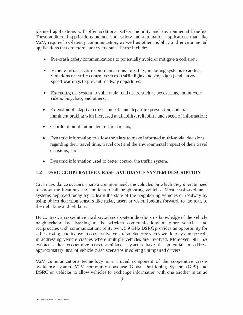
1.2.3 Example Concept of Operation for Safety Applications Forward Collision Warning (FCW) and Avoidance Feature Using V2V communications, the vehicle monitors messages from other vehicles up to 300 meters ahead. It then uses the information transmitted in safety messages from other
9 \\DC - 023165/000003 - 4675609 v1
vehicles, along with its own dynamic state information, to select lead vehicles of interest for this safety feature up to 150 meters away and in the same lane. Threat assessment calculations are performed periodically (e.g., every 100 ms) to determine, in real-time, whether there is a danger of rear-end collision with the vehicle ahead in the lane. The FCW & Avoidance feature in the HV warns the driver first (e.g., with visual icons and seat vibrations) and then automatically brakes (if the driver does not respond) if there is danger of a rear-end collision with the vehicle ahead. An illustration of a scenario for this feature is shown in Figure 4.
Figure 4 –Illustration of V2V Forward Collision Warning Feature
Intersection Movement Assist (IMA) Feature Using V2V communications, the HV monitors messages from other vehicles at an intersection up to a quarter of a mile. It then uses the information transmitted in safety messages from other vehicles, along with its own dynamic state information, to select cross path RVs of interest for this safety feature. Threat assessment calculations are performed periodically (e.g.., every 100 ms) to determine, in real-time, whether there is a danger of intersection crash with a RV in its cross path of travel. Intersection Movement Assist feature in the HV warns the driver if there is danger of a straight crossing path crash with a RV at the intersection. An illustration of this feature is shown in Figure 5, where the HV is shown to have the right of travel and the RV is shown as potentially violating the stop bar at an intersection.

10 \\DC - 023165/000003 - 4675609 v1
Figure 5 –Illustration of V2V Intersection Movement Assist Feature
1.3 SUSCEPTIBILITY OF DSRC-ENABLED SAFETY APPLICATIONS TO HARMFUL INTERFERENCE
For this section, we use as an example the cooperative Forward Collision Warning feature that provides alerts intended to assist drivers in avoiding or mitigating the rear-end collision. As described earlier, this safety feature of a V2V system may alert the driver to an approaching (or closing) conflict a few seconds before the driver would have detected such a conflict (e.g., if the driver's eyes were off-the-road), so the driver can take any necessary corrective action (e.g., steering, hard braking, etc.). Key to driver acceptance of the FCW feature is appropriate crash alert timing, which refers to the necessary underlying vehicle-to-vehicle kinematic conditions for triggering crash alerts. The goal of the alert timing approach is to allow the driver enough time to avoid the crash, and yet avoid annoying the driver with alerts perceived as occurring too early, too often or unnecessarily. The FCW equipped vehicle must be capable of detecting, classifying, tracking and monitoring “Remote Vehicles of Interest” (typically cars, trucks, motorcycles, etc.). When these estimated trajectories predict a collision course between the Following
Host Vehicle
Remote Vehicle

11 \\DC - 023165/000003 - 4675609 v1
Vehicle (FV) and Lead Vehicle (LV), a measure of crash threat (e.g.., Time-to-Collision or TTC) can be determined and then compared to the criterion used to trigger the FCW warning.
1.3.1 Time-to-Collision Drivers constantly make judgments about how to adjust vehicle speed based on what is seen in the roadway ahead. Much of collision avoidance research investigates the ability of drivers to judge when braking is necessary to avoid an accident. Additionally, once a driver is braking, the driver must monitor and adjust the level of braking input to brake successfully. Time-to-collision is frequently used in literature [9] as a descriptor of how urgent a situation has become, as well as potentially how a driver perceives stimuli during an event.
FV LV
Figure 6 –Illustration of Following and Lead Vehicle in FCW
Consider the FCW scenario shown in Figure 6. Time-to-collision can be calculated or approximated using various measures and theories. In an event with a following and a lead vehicle, time-to-collision when approaching a stationary LV, or when the LV is moving at a constant rate (zero acceleration), is computed as,
,rvrTTC ,
rvrTTC
(1) where r is the range between the vehicles and rv rv is the relative velocity, which is defined as
,FVLVr vvv ,FVLVr vvv (2) where LVv LVv is the velocity of the LV and FVv FVv is the velocity of the FV. Time-to-collision computed in this manner will be referred to as TTC. If the FV acceleration is assumed to be zero and the LV is accelerating (or decelerating), this LV acceleration is included in the equation as follows:
,22
LV
LVrr
aravv
TTC

12 \\DC - 023165/000003 - 4675609 v1
(3)
where LVa ,22
LV
LVrr
aravv
TTC LVa is the acceleration of the LV (negative for a
deceleration). Time-to-collision where acceleration of the LV (typically deceleration) is included will also be referred to as TTC.
1.3.2 Significance of Packet Error Rate (PER) and Inter-Packet Gap (IPG) In general, the cooperative FCW feature requires that a vehicle has good real-time situational awareness and tracking of its neighboring vehicles, and then, based on such situational awareness, the system feature can provide advisory and warning information to the driver. Two related performance metrics are important to the cooperative FCW system:
PER: Ratio, expressed as a percentage, of the number of missed packets (i.e. safety messages) at a receiver from a particular transmitter and total number of packets sent by that transmitter; and IPG: Time, expressed in milliseconds, between successive successful packet (i.e. safety message) receptions from a particular transmitter.
Clearly, IPG is caused by PER, and a large IPG would result in poor performance of the cooperative FCW safety system by the vehicle not being able to perform good real-time situational awareness and tracking of its neighboring vehicles, as well as not being able to provide timely warnings of an imminent rear-end crash to the driver. The USDOT’s New Car Assessment Program (NCAP) FCW requirements are provided in Table 2. The FCW system must meet each of three crash alert test requirements. Each of the tests is to be conducted under clear, daytime weather conditions, and involves the FCW-equipped vehicle approaching a Lead Vehicle on a straight road at 45 MPH (72.4 kph). Furthermore, an alert must be issued prior to the time-to-collision (TTC) criterion associated with each test (shown in Table 2) in at least five of seven test trials, and must not fail to meet the criterion on two consecutive trials. [10]

13 \\DC - 023165/000003 - 4675609 v1
Table 2. Overview of United States Department of Transportation New Car Assessment Program (NCAP) Forward Collision Warning (FCW) confirmation test requirements
The LVD scenario, as shown in Figure 7, is presented for discussion.
FV LVInitially, FVfollows LV
Then, LV beginsto brake
Figure 7 –Lead Vehicle Decelerating Scenario
Based on the LVD scenario described in Table 2, the cooperative FCW system must be capable of issuing an alert at a theoretical minimum TTC of 2.40 seconds. Based on Equation 3, the initial TTC when the lead vehicle initiates its braking of 0.3g is 4.5175 seconds. Assuming that the driver of the following vehicle is issued an FCW alert, following which he takes action to apply braking to his vehicle at a deceleration of 0.6 g after a driver reaction time of 1.5 seconds, the following statements can be made:
If the IPG is significant such that the warning is provided by the system with a delay greater than 3.0175 seconds after the lead vehicle initiates braking, the driver will have less than 1.5 seconds to react to the warning. Based on the

14 \\DC - 023165/000003 - 4675609 v1
assumed driver reaction time of 1.5 seconds, the following vehicle will crash into the lead vehicle with a significant Delta Speed of 13.3 m/s.
If the IPG is such that the warning is provided by the system with a delay of 2.5175 seconds after the lead vehicle initiates braking, the driver will have the time to react to the warning. In this situation the warning is provided at a TTC of 2.0 seconds. However, based on the assumed driver reaction time of 1.5 seconds, the following vehicle will still crash into the lead vehicle with a Delta Speed of 10.1 m/s.
If the IPG is such that the warning is provided by the system with a delay of 2.1175 seconds after the lead vehicle initiates braking, the driver will have sufficient time to react to the warning. In this situation, the warning is provided at a TTC of 2.4 seconds. However, based on the assumed driver reaction time of 1.5 seconds, the following vehicle will still crash into the lead vehicle with a Delta Speed of 7.0 m/s.
If the IPG is such that the warning is provided by the system with a delay of 1.675 seconds after the lead vehicle initiates braking, the driver will have sufficient time to react to the warning. In this situation the warning is provided at a TTC of 2.8425 seconds. Based on the assumed driver reaction time of 1.5 seconds, the following vehicle will be prevented from crashing into the lead vehicle.
Thus, for the stated driver to prevent a crash in this scenario, the warning should be provided at a TTC larger than 2.84 seconds. However, prior to issuing this alert, the system must detect, classify, and estimate the range and range-rate to the lead vehicle and accommodate various system latencies (i.e., network communication, interface delays, etc.). Consequently, in order to ensure robust operation, the cooperative FCW system must be able to detect, classify and estimate the range (TTC) to the target lead vehicle at a TTC of at least 3.5 seconds. Therefore, in this example, the IPG should be less than 1.0 seconds for initial detection, and subsequently to track the target vehicle, classify and estimate the threat continuously, the IPG from the lead vehicle should be typically low, nominally 100 ms until the warning is provided. UNII devices operating in the DSRC Band can cause significant interference to packet (i.e. safety messages) reception in cooperative safety systems, leading to unknown and perhaps very high IPG and PER. Consequently, they could negatively affect the performance of cooperative safety applications and the benefits to be derived from these safety systems. IPG and PER would also affect security verification in cooperative safety systems since the messages with certificates attached may be lost or delayed due to interference from UNII devices in the DSRC Band. Significant real world testing is required to assess the consequence of interference from UNII devices.

15 \\DC - 023165/000003 - 4675609 v1
1.4 CO-CHANNEL INTERFERENCE MECHANISMS This section describes a number of the mechanisms that could be involved in co-channel interference if DSRC and Wi-Fi technologies share the same spectrum. Further technical details regarding these mechanisms are contained in a later section entitled – “Co-channel Interference Analysis”.
1.4.1 Lower Layer Sensing Mechanisms
Although both DSRC and Wi-Fi technologies share the lower layer technologies of IEEE 802.11, there are differences in the options selected from the IEEE 802.11 standard. One of the most significant potential causes of co-channel interference is the different channel width of 10 MHz used by DSRC, as compared to the 20 MHz minimum channel width used for Wi-Fi. The 10 MHz channel width is allowed under IEEE 802.11, and was selected for DSRC for specific characteristics of vehicles traveling at highway speeds. The 10 MHz channels have been thoroughly field-tested to support V2V cooperative safety applications among vehicles traveling at highway speeds.
As a result of the different channel widths used by DSRC and Wi-Fi technologies, the Carrier Sense Multiple Access (CSMA) mechanism in IEEE 802.11 may not be interoperable between these two technologies. The DSRC devices have been designed to detect the IEEE 802.11 preamble within the 10 MHz channel width, so these devices may not be able to detect the Wi-Fi packet preamble sent on a 20 MHz channel. The current Wi-Fi devices have not been designed to detect channels that are 10 MHz wide, so they may need to be modified to detect the 10 MHz DSRC channels in order to detect DSRC packets and avoid interfering with DSRC transmissions. Wi-Fi devices would also need to be modified to be capable of verifying that two or more DSRC channels are clear simultaneously.
1.4.2 Application Layer Sensing Mechanisms
DSRC crash-avoidance safety applications are expected to experience channel congestion in vehicle traffic situations that are likely to occur under realistic roadway conditions, especially during peak traffic periods in major metropolitan centers. Application layer protocols that adjust transmission power and/or BSM transmission interval timing based upon the likelihood of vehicles being in a conflict situation have been developed to address the expected channel congestion resulting from these dense traffic situations. It is expected that all DSRC devices supporting V2V cooperative crash-avoidance safety applications will participate in this application layer channel congestion mitigation protocol in order to ensure that the appropriate vehicles are able to communicate effectively. Non-DSRC devices will need to sense the V2V safety use of the DSRC channel and move to another channel, or else utilize the application layer channel congestion mitigation protocol in order to share the channel without causing harmful interference to the V2V safety applications.
16 \\DC - 023165/000003 - 4675609 v1
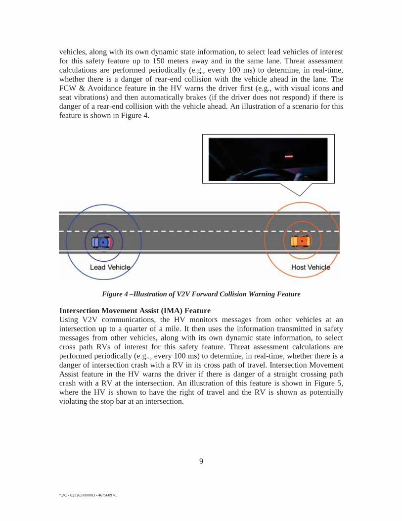
1.4.3 Power Disparity Challenge The current implementations of V2V safety applications utilize DSRC transmission power in the range of 18-20 dBm EIRP. This corresponds roughly to a maximum of 100 mW in transmitter output. This power level has been shown through significant field testing to provide suitable range to support the V2V crash-avoidance safety applications without creating excessive channel congestion outside the range necessary to support these safety applications. If non-DSRC devices are to share the spectrum with DSRC devices and are operated with much higher power, such as “…the lesser of 1 Watt and 17dBm+10 Log (B) where B is 26 dB emission bandwidth,” then the large power differential will contribute to extensive harmful interference for the DSRC V2V safety applications. With critical V2V safety applications operating at much lower power levels in the proposed shared DSRC spectrum, the prospect of asymmetrical sensing issues represents a major concern. The transmission range of the U-NII devices will be much farther than the V2V DSRC safety devices, due to the power differential. The U-NII devices are likely to initiate transmissions to the DSRC devices, due to their limited ability to sense the lower-powered DSRC devices within the range of the U-NII units. When the U-NII devices cannot detect the lower-powered DSRC devices, U-NII packets will be sent at the same time as the DSRC units are sending packets for critical safety applications, causing the DSRC packets to be unreadable by DSRC receiving devices. In this situation, it is likely that significant sequences of DSRC packets supporting crash-avoidance safety applications could be unreadable.
1.4.4 Aggregate U-NII Noise Floor Mechanisms In major metropolitan areas, channel congestion on DSRC V2V safety channels is expected to be encountered in fairly commonly-occurring traffic situations. These major metropolitan areas are also where significant numbers of deployed U-NII devices likely will be operated. Even if the U-NII devices were running at very low power levels, or operating at significant distance from vehicles using DSRC to support V2V safety applications, the aggregation of many such U-NII devices in operation would likely raise the noise floor within the DSRC channel, causing potentially harmful interference with DSRC V2V cooperative crash-avoidance safety applications.
1.5 CO-CHANNEL INTERFERENCE ANALYSIS U-NII-4 devices sharing the DSRC band could provide harmful interference to incumbent DSRC operations unless more constraints on the operation of the U-NII-4 devices are required. The following proposed U-NII-4 characteristics and related FCC NPRM paragraph numbers are helpful when considering such spectrum sharing:
17 \\DC - 023165/000003 - 4675609 v1
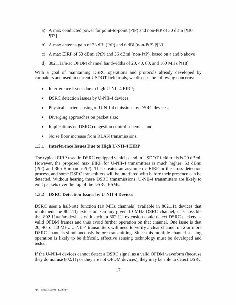
a) A max conducted power for point-to-point (PtP) and non-PtP of 30 dBm [¶30, ¶97]
b) A max antenna gain of 23 dBi (PtP) and 6 dBi (non-PtP) [¶33]
c) A max EIRP of 53 dBmi (PtP) and 36 dBmi (non-PtP), based on a and b above
d) 802.11a/n/ac OFDM channel bandwidths of 20, 40, 80, and 160 MHz [¶18]
With a goal of maintaining DSRC operations and protocols already developed by carmakers and used in current USDOT field trials, we discuss the following concerns:
Interference issues due to high U-NII-4 EIRP;
DSRC detection issues by U-NII-4 devices;
Physical carrier sensing of U-NII-4 emissions by DSRC devices;
Diverging approaches on packet size;
Implications on DSRC congestion control schemes; and
Noise floor increase from RLAN transmissions.
1.5.1 Interference Issues Due to High U-NII-4 EIRP The typical EIRP used in DSRC equipped vehicles and in USDOT field trials is 20 dBmi. However, the proposed max EIRP for U-NII-4 transmitters is much higher: 53 dBmi (PtP) and 36 dBmi (non-PtP). This creates an asymmetric EIRP in the cross-detection process, and some DSRC transmitters will be interfered with before their presence can be detected. Without hearing these DSRC transmissions, U-NII-4 transmitters are likely to emit packets over the top of the DSRC BSMs.
1.5.2 DSRC Detection Issues by U-NII-4 Devices DSRC uses a half-rate function (10 MHz channels) available in 802.11a devices that implement the 802.11j extension. On any given 10 MHz DSRC channel, it is possible that 802.11a/n/ac devices with such an 802.11j extension could detect DSRC packets as valid OFDM frames and thus avoid further operation on that channel. One issue is that 20, 40, or 80 MHz U-NII-4 transmitters will need to verify a clear channel on 2 or more DSRC channels simultaneously before transmitting. Since this multiple channel sensing operation is likely to be difficult, effective sensing technology must be developed and tested. If the U-NII-4 devices cannot detect a DSRC signal as a valid OFDM waveform (because they do not use 802.11j or they are not OFDM devices), they may be able to detect DSRC

18 \\DC - 023165/000003 - 4675609 v1
packets as noise energy using physical carrier sensing. However, this physical carrier detection level is relatively high (about -65dBm). Initial DSRC communications at max 300m range occur with a received signal strength (RSS) as low as -92 to -94dBm. U-NII-4 devices simply will not be able to detect and avoid interference at such low RSS values. The issue of nomadic departures and arrivals will still apply, even if physical carrier sensing can operate at such low RSS levels.
1.5.3 Physical Carrier Sense of U-NII-4 Emissions by DSRC Devices Current DSRC devices cannot easily detect 20, 40, 80, or 160 MHz transmissions in the DSRC band. Although not required under the Commission’s rules, the manufacturers of DSRC devices might feel compelled to attempt a redesign of such devices in order to use physical carrier sensing to sense U-NII-4 transmissions in the DSRC spectrum. Assuming high packet traffic and channel usage from U-NII-4 devices, if DSRC transmitters did back off upon sensing U-NII-4 packets, the DSRC devices would likely be suspended for significant periods of time that could result in BSM latency and higher DSRC packet errors. This would certainly reduce the efficacy of the DSRC systems.
1.5.4 Diverging Approaches on Packet Size DSRC BSMs sent are small broadcasted packets of 250 to 350 bytes (0.5ms range for transmit duration), which allows very short transmissions using the WAVE Short-Message (WSM) protocol, at a robust 6 mbps burst data rate, and conveyed among highly-mobile, ad hoc nodes. Although each transceiver sends only 10 BSMs per second, the packet success rate must be high in order to track the movement of nearby vehicles and determine with confidence a warning status for the driver. U-NII-4 devices such as IEEE 802.11ac mandate the use of longer aggregated packets up to 5.5ms in length. A single U-NII-4 packet could collide with a number of BSMs, even assuming the U-NII-4 device had detected no packets at the time immediately preceding its own transmission. Therefore, it would likely be necessary to limit the U-NII-4 devices to a specific short packet length interval and a very low duty cycle in order to avoid harmful interference to the DSRC communications.
1.5.5 Implications on DSRC Congestion Control Schemes DSRC defines and detects a range of acceptable packet congestion levels and implements application-level protocols when needed to lower and maintain a level of performance. It is not known if it would be feasible for U-NII-4 devices to be aware of the DSRC application layer channel congestion mitigation factors or protocols. Further, it is likely that U-NII-4 nodes will also be concentrated in major urban areas where V2V channel congestion is most likely. This conjunction of situations illustrates the need to create interference mitigation approaches such that U-NII-4 devices can effectively sense and

19 \\DC - 023165/000003 - 4675609 v1
vacate the congested DSRC channels being used for safety applications, especially in major metropolitan areas.
1.5.6 Noise Floor Increase from U-NII-4 Transmissions DSRC safety communications includes V2V links to the 300m range, when RSS is low, safety links begin tracking, and PER must be low. Because proposed U-NII-4 transmissions in the DSRC band overlap the DSRC channels and have undetectable preambles, they would be detected by DSRC receivers as high noise signals. As the highly mobile nomadic vehicles pass through a U-NII-4 hotspot or the large coverage area of a U-NII-4 Wireless Internet Service Provider (WISP), the noise floor in the DSRC mobile receivers will be raised. This makes receiving BSMs difficult, particularly at the 200 to 300 meter range, where vehicles must first be tracked. It is not clear what technical mitigation strategies are available to counter this effect and allow sharing of the channel with U-NII-4 devices while maintaining reliable V2V links to support V2V and related low-latency safety applications. U-NII-4 transmitters inside the DSRC band add significantly more noise to adjacent DSRC channels than DSRC transmitters themselves. This is shown in the spectral plot below. The U-NII-4 TX mask (example 20 MHz transmitter) is shown in blue. The DSRC mask is shown in black. A DSRC mask-compliant 20 dBm signal is shown in green. The U-NII-4 out-of-band mask segments are overlaid on the 10 MHz signal, although they apply to a 20 MHz waveform. The comparison is valid although U-NII-4 operates in wider bandwidths because they can also operate at 10 dB to 20 dB more EIRP than typical in-vehicle DSRC transmitters. As one can observe, the U-NII-4 mask allows much more noise in adjacent bands. This may be acceptable for hot spots with clustered clients separated by frequency from other hotspots, but OBUs on adjacent frequencies are only separated by a lane width. In-band U-NII-4 transmitters will likely generate excessive noise that will de-sense and degrade the safety links.

20 \\DC - 023165/000003 - 4675609 v1
1.6 INTERFERENCE DUE TO STRONG OUT-OF-BAND SIGNALS This section describes a number of the mechanisms that could be expected to be involved with interference originating outside the particular DSRC channel. Further technical details regarding these mechanisms are contained in the section following this one, titled: “Out-of-band Interference Analysis”.
1.6.1 Adjacent DSRC Channel Interference Mechanisms
The DSRC channel to be used for V2V cooperative crash-avoidance safety (Channel 172) was chosen to be purposely separated from higher-powered DSRC control and intersection channels in order to minimize adjacent channel and next-adjacent channel interference. This spectral separation of DSRC channels was implemented even though there are low-density expectations for RSEs compared to U-NII access points - especially in major metropolitan areas.
If U-NII devices are sharing the DSRC spectrum and operating at higher power levels, such as “…the lesser of 1 Watt and 17 dBm+10 Log (B) where B is 26 dB emission bandwidth,” they would be expected to cause harmful interference to V2V safety applications when operating on channels adjacent to the DSRC channel used for V2V safety.
1.6.2 Adjacent U-NII Band Interference Mechanisms
Even if U-NII devices were confined to spectrum that was not within the DSRC range, the U-NII devices could cause harmful interference to the V2V safety applications if the U-NII bands were immediately, or closely adjacent to, the DSRC channel being used for V2V safety. This is especially true with the maximum power levels for U-NII devices

21 \\DC - 023165/000003 - 4675609 v1
mentioned above. In addition to the higher power levels, higher gain antennas are also expected to be used by the U-NII devices. These higher gain antennas are expected to increase the likelihood of harmful interference to the DSRC safety applications from U-NII devices operating in adjacent bands.
1.7 OUT-OF-BAND INTERFERENCE ANALYSIS DSRC transmissions are subject to interference due to unwanted emissions from U-NII-3 devices. They are also subject to interference from emissions outside the occupied channel of a U-NII-4 device. U-NII-4 devices can also provide co-channel interference to DSRC transmissions, as addressed in an earlier section. Unwanted emission limits proposed by the Commission for the U-NII-3 band are: “below -17 dBm/MHz within 10 megahertz of the band edge, and below -27 dBm/MHz beyond 10 megahertz of the band edge.” [¶34] The Commission invites “comment on whether any of these techniques [including limiting unwanted emissions] would be beneficial in protecting other incumbents from interference, not only in the U-NII-2C band but also in other segments of the 5 GHz band.” [¶53]. While the Commission proposes OOBE limits for an unlicensed device operating in the U-NII-4 band, it does not define out-of-channel limits for such a device within the U-NII-4 band. For example, consider a U-NII-4 device that occupies 20 MHz Ch. 177 (5.875-5.895 GHz), which corresponds to 10 MHz DSRC channels 176 and 178. There are no defined limits on the emissions of such a device in non-overlapping 10 MHz DSRC channels 172, 174, 180, 182, or 184. It is clear that without such limits the U-NII-4 device can interfere with the reception of a DSRC transmission in those non-overlapping channels. The draft IEEE P802.11ac D5.0 standard includes transmit spectral mask limits, which impose relative out-of-channel emission constraints. An example transmit spectral mask for 20 MHz occupied bandwidth is shown in Figure 9 below. Given a transmit power in the occupied channel, it is possible to compute worst case out-of-channel emissions using this mask, and the impact of such emissions on DSRC packet reception.

22 \\DC - 023165/000003 - 4675609 v1
Figure 8 –Example 20 MHz Transmit Spectrum Mask (copied from IEEE P802.11ac D5.0)
We consider the following cases:
Impact of unwanted emissions from a U-NII-3 device on a DSRC transmission in 10 MHz DSRC channel 172;
Impact of unwanted emissions from a U-NII-3 device on a DSRC transmission in a 10 MHz DSRC channel above channel 172, e.g.., channel 174;
Impact of unwanted emissions from a 20 MHz U-NII-4 device on a DSRC transmission in an adjacent 10 MHz channel, e.g.., from a U-NII-4 transmission in 20 MHz channel 177 on a DSRC transmission in 10 MHz DSRC channel 174 or 180;
Impact of unwanted emissions from a 20 MHz U-NII-4 device on a DSRC transmission in a second-from-adjacent 10 MHz channel, e.g.., from a U-NII-4 transmission in 20 MHz channel 177 on a DSRC transmission in 10 MHz DSRC channel 172 or 182; and
Impact of unwanted emissions from a 20 MHz U-NII-4 device on a DSRC transmission in a third-from-adjacent 10 MHz channel, e.g.., from a U-NII-4 transmission in 20 MHz channel 177 on a DSRC transmission in 10 MHz DSRC channel 184.
1.7.1 Impact of Unwanted Emissions from a U-NII-3 Device on a DSRC Transmission in 10 MHz DSRC Channel 172
DSRC 10 MHz Ch. 172 occupies the 5.855-5.865 GHz band. The U-NII-3 band edge is 5.850 GHz. According to the proposed unwanted emission rule for U-NII-3 [¶34] there can be as much as -17 dBm/MHz in the 5.855-5.860 GHz band, for a total of 100 microwatts. Furthermore, there can be as much as -27 dBm/MHz in the 5.860-5.865 GHz

23 \\DC - 023165/000003 - 4675609 v1
band, for a total of 10 microwatts. Therefore, there can be 110 microwatts of unwanted emission (-9.6 dBm) in Ch. 172 from a U-NII-3 device. DSRC transmissions use 20 dBm EIRP transmit power by default. They also use QPSK with ½ rate coding [Ref. IEEE 802.11-2012] by default, the successful decoding of which requires approximately 7 dB of Signal-to-interference-and-noise (SINR) ratio. Given the DSRC transmit power, U-NII-3 unwanted emission power, and 7 dB SINR requirement, there is a 20 + 9.6 – 7 = 22.6 dB power margin for the DSRC signal at the transmission point. However, both the DSRC signal and the U-NII-3 interference power experience attenuation in reaching the DSRC receiver. The DSRC signal can be correctly decoded if the DSRC signal attenuation is no more than 22.6 dB higher than the U-NII-3 interference attenuation. Given a path loss model, the 22.6 dB power margin can also be thought of as a relative distance margin. If, for simplicity, one assumes a path loss exponent of 2, the 22.6 dB power margin represents an increase in distance of about 13.5 times, i.e. the DSRC devices can be no more than 13.5 times farther apart than the U-NII-3 device is from the DSRC receiver. Many collision avoidance scenarios require safety message communication ranges on the order of 300 meters between DSRC devices. If the DSRC transmitter is 300 meters from the DSRC receiver, a U-NII-3 device with worst case unwanted emissions whose transmission overlaps in time with the DSRC transmission will likely cause harmful interference if it is within 300/13.5 = 22.2 meters of the DSRC receiver. Figure 9 illustrates a scenario in which a DSRC transmission from a leading car in DSRC Channel 172 overlaps in time with a U-NII transmission from a device in a nearby building. The U-NII-device is within a radius X of a trailing car that is 300 meters from the leading car. According to this analysis, if the U-NII device is within 22.5 meters of the trailing car, its unwanted emission in Channel 172 can prevent successful decoding of the DSRC transmission.

24 \\DC - 023165/000003 - 4675609 v1
Figure 9 –Out-of-Band Interference Scenario
1.7.2 Impact of Unwanted Emissions from a U-NII-3 Device on a DSRC Transmission in 10 MHz DSRC Ch. 174
DSRC 10 MHz Ch. 174 occupies the 5.865-5.875 GHz band. In this channel, and higher numbered channels, unwanted emissions from a U-NII-3 device can have a power density as high as -27 dBm/MHz, or 20 microwatts (-17 dBm) for the 10 MHz channel. Using the same assumptions as above there is a 30 dB power margin, i.e. the DSRC transmission can tolerate as much as 30 dB additional attenuation in reaching the DSRC receiver compared to that experienced by the worst case unwanted emission energy from the U-NII-3 device in reaching the DSRC receiver. If the DSRC transmitter is 300 meters from the DSRC receiver, the U-NII-3 device transmitting an overlapping packet will likely cause harmful interference if it is within 300/32 = 9.4 meters of the DSRC receiver.
1.7.3 Impact of Unwanted Emissions from a U-NII-4 Device in 20 MHz Ch. 177 on a DSRC transmission in adjacent 10 MHz DSRC Ch. 174 or 180
DSRC 10 MHz Ch. 174 occupies the 5.865-5.875 GHz band, and Ch.180 occupies the 5.895-5.905 GHz band. These channels are adjacent to 20 MHz Ch. 177, which occupies the 5.875-5.895 GHz band. See Figure 10 below:

25 \\DC - 023165/000003 - 4675609 v1
Figure 10 –Example: Interference from U-NII 20 MHz Ch. 177
According to the Commission’s proposed rules, a U-NII-4 device transmitting in 20 MHz Ch. 177 can emit as much as 17 dBm/MHz in its occupied channel. [¶97] As noted above, there are no limits on unwanted out-of-channel emissions in the Commission’s rules. However, using the transmit spectrum mask in Figure 8, one can compute worst case unwanted out-of-channel emissions for a device that conforms to the draft standard. In this case, the emissions are relative to the in-channel power spectral density of 17 dBm/MHz. Integrating over the frequency offset range 10 to 20 MHz, the power of unwanted emissions in an adjacent 10 MHz channel can be as high as 6.3 dBm (we approximate the integral with a sum using power spectral density granularity 100 kHz). Using the same assumptions as above, i.e. 20 dBm DSRC transmission and 7 dB SINR required, the power margin between the DSRC signal and the U-NII-4 unwanted emission is only 6.7 dB. This translates to a distance factor of 2.2. If the DSRC transmitter is 300 meters from the DSRC receiver, the U-NII-4 device transmitting an overlapping packet will likely cause harmful interference if it is within 300/2.2 = 138 meters of the DSRC receiver in Ch. 174 or Ch. 180.
1.7.4 Impact of Unwanted Emissions from a U-NII-4 Device in 20 MHz Ch. 177 on a DSRC transmission in second-adjacent 10 MHz DSRC Ch. 172 or 182
Using a similar analysis to the prior section, the power of the unwanted emissions in 10 MHz channels second-from-adjacent to a 20 MHz U-NII-4 transmission can be obtained by integrating over the frequency offset range 20 to 30 MHz in Figure 8. If the U-NII-4 20 MHz transmission uses a maximum power density of 17 dBm/MHz, this unwanted emission power can be as high as -5.6 dBm. The power margin between a second-adjacent-channel DSRC signal and U-NII-4 interference is therefore 18.6 dB. This translates to a distance factor of 8.5. If the DSRC transmitter is 300 meters from the DSRC receiver, the U-NII-4 device transmitting an
Ch. 174
U-NII-4 Ch. 177 20 MHz
Ch. 180
Ch. 172
Ch. 184
Adjacent to U-NII
Second-adjacent to U-NII
Third-adjacent to U-NII

26 \\DC - 023165/000003 - 4675609 v1
overlapping packet will likely cause harmful interference if it is within 300/8.5 = 35 meters of the DSRC receiver in Ch. 172 or Ch. 182.
1.7.5 Impact of Unwanted Emissions from a U-NII-4 Device in 20 MHz Ch. 177 on a DSRC transmission in third-adjacent 10 MHz DSRC Ch. 184
Using a similar analysis to that used in the prior section, the power of the unwanted emissions in 10 MHz channels third-from-adjacent to a 20 MHz U-NII-4 transmission can be obtained by integrating over the frequency offset range 30 to 40 MHz in Figure 8. The mask is flat here at -40 dBm, so if the U-NII-4 20 MHz transmission uses maximum power density 17 dBm/MHz, this unwanted emission power in 10 MHz can be as high as -13 dBm. The power margin between a third-adjacent-channel DSRC signal and U-NII-4 interference is therefore 26 dB. This translates to a distance factor of 20. If the DSRC transmitter is 300 meters from the DSRC receiver, the U-NII-4 device transmitting an overlapping packet will likely cause harmful interference if it is within 300/20 = 15 meters of the DSRC receiver in Ch. 184. While Sections 1.7.3-1.7.5 assume the U-NII device uses maximum power, the interference resulting from even moderate power (7 dBm/MHz) U-NII-4 transmissions could still be significant. A 10 dB reduction in U-NII transmit power increases the power margin by 10 dB. In the case of a DSRC transmitter that is 300 meters from the DSRC receiver, the 10 dB change in margin means the interferer could be approximately 4.4 times closer before it caused DSRC packet decoding failure. For example, the adjacent channel interference range (Section 1.7.3) would be reduced from 138 meters to 31 meters.
1.8 CONCLUSIONS V2V communications technology is a crucial component of the cooperative crash-avoidance system. 5.9 GHz DSRC is the only technology that has been proven to support the range and latency requirements of the cooperative crash-avoidance system. Besides the initial focus on the deployment of 5.9 GHz DSRC for cooperative crash-avoidance, other uses of the DSRC spectrum are under development, or anticipated. These include public safety applications, pre-crash damage mitigation applications, automated driving systems, support for V2V safety security system communications, as well as mobility and environmental applications. Based on deployment planning work underway in the United States, and complementary work in Europe and Japan, it is envisioned that this DSRC-based V2V crash-imminent safety system will be extended to include other applications that will require additional messages and additional channels for communication. These applications will offer additional safety, mobility and environmental benefits. These additional applications

27 \\DC - 023165/000003 - 4675609 v1
include both safety and automation applications that also require low-latency communication, as well as other mobility and environmental applications that are more latency tolerant. Although both DSRC and Wi-Fi technologies share the lower layer technologies of IEEE 802.11, there are significant differences in the options selected from the IEEE 802.11 standard. As a result of the different channel widths used by DSRC and Wi-Fi technologies, the Carrier Sense Multiple Access (CSMA) mechanism in IEEE 802.11 may not be interoperable between these two technologies. Current Wi-Fi receivers would need to be designed to detect possibly multiple 10 MHz DSRC channels in order to detect DSRC packets and avoid interfering with DSRC transmissions. Application layer protocols that adjust transmission power and/or BSM transmission interval timing based upon the likelihood of vehicles being in a conflict situation have been developed to address the expected channel congestion resulting from these dense traffic situations. Non-DSRC devices sharing the DSRC spectrum would need to participate in this application layer channel congestion mitigation protocol in order to ensure that the appropriate vehicles are able to communicate effectively, or else employ interference mitigation approaches that allow U-NII-4 devices to vacate the congested DSRC channels being used for safety applications, especially in major metropolitan areas. Because U-NII-4 transmissions in the DSRC band overlap the DSRC channels and could have undetectable preambles, they are detected by DSRC receivers as high noise signals. It is not clear what technical mitigation strategies might be used to counter this effect and allow sharing of the channel with U-NII-4 devices while maintaining reliable V2V links to support V2V and related low-latency safety applications. This situation also suggests that U-NII-4 devices would likely need some approach to vacate congested DSRC safety channels in major metropolitan areas. U-NII devices have the potential to cause harmful interference to DSRC transmissions due to unwanted out-of-band emissions. This harmful interference could come from a U-NII device located in the same vehicle as the DSRC receiver, or in an adjacent vehicle. Furthermore, in the scenarios without an intervening channel between the U-NII device and the DSRC transmission, the harmful interference could come from a U-NII device located in a building nearby the vehicle with the DSRC receiver. The potential for harmful interference from U-NII devices could span multiple DSRC transmissions. For example, a 4-millisecond U-NII transmission could interfere with the reception of seven DSRC transmissions spaced at 600 microsecond intervals. The harmful interference scenarios discussed above could be persistent throughout the time period that the U-NII device and the DSRC receiver are within range of each other. Some type of function that recognizes one instance of interference and avoids subsequent instances would need to be developed.

28 \\DC - 023165/000003 - 4675609 v1
Additional interference mitigation technologies may also be needed in order to satisfy the requirement that U-NII devices do not cause harmful interference to incumbent DSRC operations. This additional mitigation could be achieved in a variety of ways, for example through a specific DSRC detector in the U-NII device, such that upon detection of a DSRC transmitter the U-NII device ceases to use its current band. Another example would be more stringent unwanted emission limits for U-NII-3 and U-NII-4 devices. For all the reasons mentioned above, extensive field- and bench-testing is required for any U-NII algorithm proposed for channel sharing with DSRC devices.
1.9 REFERENCES 1. U.S. Department of Transportation, National Highway Traffic Safety Administration,
Frequency of Target Crashes for IntelliDrive Safety Systems, DOT HS 811 381 vi (2010).
2. Amendment of Parts 2 and 90 of the Commission’s Rules to Allocate the 5.850-5.925 GHz Band to the Mobile Service for Dedicated Short-Range Communications of Intelligent Transportation Services, ET Docket No. 98-95, RM-9096, Report and Order, 14 FCC Rcd 18221 ¶ 1.1 (1999).
3. U.S. Department of Transportation, National Highway Traffic Safety Administration, Vehicle Safety Communications Project-Final Report, USDOT HS 810 591 (2006).
4. Fan Bai et al., Toward Characterizing and Classifying Communication-based Automotive Applications from a Wireless Networking Perspective (2006), available at http://www.cse.sc.edu/~wyxu/719Spring12/papers/bai-vanet-application_characteristics.pdf.
5. U.S. Department of Transportation, National Highway Traffic Safety Administration, Vehicle Safety Communications – Applications (VSC-A) Final Report, USDOT HS 811 492A (2011).
6. U.S. Department of Transportation, Research and Innovative Technology Administration, Intelligent Transportation Systems (ITS) Standards Program Strategic Plan for 2011-2014: Final Report-April 2011, FHWA-JPO-11-052 17 (2011).
7. Society of Automotive Engineers, DSRC Committee, SAE J2735 Dedicated Short-Range Communications (DSRC) Message Set Dictionary, Revision 35, (2009).
8. U.S. Department of Transportation, National Highway Traffic Safety Administration, General Estimates System Coding and Editing Manual (2006).
9. U.S. Department of Transportation, National Highway Traffic Safety Administration, Development of an FCW Algorithm Evaluation Methodology with Evaluation of Three Alert Algorithms, Final Report, USDOT HS 811 145 2-6 (2009).
10. Eric Raphael, et. al., Society of Automotive Engineers International, Development of a Camera-Based Forward Collision Alert System, SAE 2011-0100579 7 (2011).

\\DC - 023165/000003 - 4675609 v1
ATTACHMENT 1

2 \\DC - 023165/000003 - 4675609 v1

3 \\DC - 023165/000003 - 4675609 v1

4 \\DC - 023165/000003 - 4675609 v1

5 \\DC - 023165/000003 - 4675609 v1

6 \\DC - 023165/000003 - 4675609 v1

7 \\DC - 023165/000003 - 4675609 v1

8 \\DC - 023165/000003 - 4675609 v1

9 \\DC - 023165/000003 - 4675609 v1

10 \\DC - 023165/000003 - 4675609 v1
11 \\DC - 023165/000003 - 4675609 v1

12 \\DC - 023165/000003 - 4675609 v1

13 \\DC - 023165/000003 - 4675609 v1

14 \\DC - 023165/000003 - 4675609 v1

15 \\DC - 023165/000003 - 4675609 v1