allegheny county health department air quality program 301
TRANSCRIPT
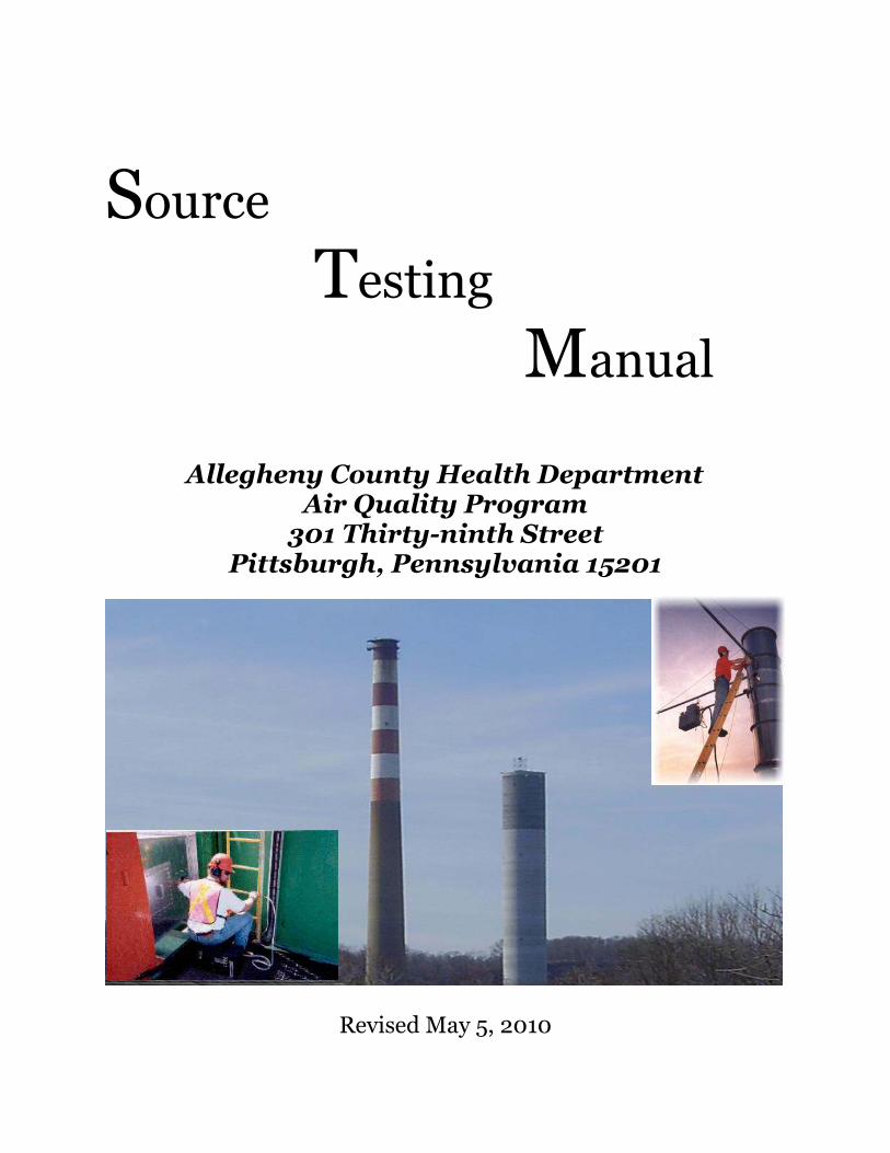
Source Testing
Manual Allegheny County Health Department
Air Quality Program 301 Thirty-ninth Street
Pittsburgh, Pennsylvania 15201
Revised May 5, 2010

INTRODUCTION
This manual is provided by the Air Quality Program of the Allegheny County Health
Department to assist the owners, managers, and operators of regulated sources, consultants, and
members of this agency, to understand and comply with the procedures of source sampling.
Specific detail is included to guide source sampling through the required functions of the
Air Quality Program. Organizational structures are presented with functional duties outlined to
permit all concerned the necessary information as to all sampling responsibilities.
Sampling and analytical procedures likewise cannot always be exactly defined because
they will vary with the purposes intended and the circumstances. There are specific procedures
included, however, which are adaptable to most sampling requirements.

PURPOSES
Source sampling or emission testing, as applied to air pollution is the procedure whereby
a representative sample is removed from some larger, contaminant-bearing gas stream confined in
a duct or stack. This sample is then subjected to further analysis, and the contaminant
concentrations are related to the parent gas stream to determine total quantities. Because the
sample extracted from the main gas stream usually represents a very small fraction of the total
volume, extreme care should be exercised in obtaining a representative sample. Additionally,
because of the many and variable factors encountered in sampling gas streams, complex methods
must frequently be used to obtain representative samples.
Source sampling frequently is employed to answer a variety of questions of which the
main one is: What are the quantities and concentrations of emissions? Subsequent questions that
can be answered from this basic determination include:
1. Is the process in compliance with the present or expected
emission regulations?
2. What is the efficiency of existing pollution control
equipment?
3. What effect do various process variables have on
emissions?
4. Is a valuable product or by-product being emitted?
5. What are the potential (uncontrolled) emissions of
various processes?
6. What further information is required, including legal
enforcement actions, to attain compliance?
7. Is the operation of the process within approved
surveillance limits?
8. Is continuous monitoring of emissions or parameter
necessary?

P R E F A C E
The Air Quality Program regularly uses the test methods described in this manual. The
Program may accept other test methods, as equivalent, suitable or required, in accordance with
the provisions of the applicable regulations. Methods may be re-evaluated, revised, added,
deleted or altered as more information becomes available and the applications are approved.
It is the intent of this manual to outline acceptable standard methods for determining
compliance with the applicable regulations and for other purposes. All elements of a standard
method may not always be exactly applicable or justified in a given situation; experience and
intelligent judgment may be required to develop a usable sampling plan.
Since sampling results may have important legal consequences, and deviations from the
standard methods set forth herein should be approved in advance by the Director in accordance
with the applicable regulations. All such deviations should be thoroughly documented in the test
protocol and reports.

TABLE OF CONTENTS
Chapter 1
EPA Method
1 Sample and Velocity Traverses for Stationary Sources.
1A Sample and Velocity Traverses for Stationary Sources with
Small Stacks or Ducts.
Chapter 2
EPA Method
2 Determination of Stack Gas Velocity and Volumetric Flow Rate
(Type S Pitot Tube).
2A Direct Measurement of Gas Volume Through Pipes and Small
Ducts.
2B Determination of Exhaust Gas Volume Flow Rate From
Gasoline Vapor Incinerators.
2C Determination of Stack Gas Velocity and Volumetric Flow Rate
From Small Stacks or Ducts (Standard Pitot Tube).
2D Measurement of Gas Volume Flow Rates on Small Pipes and
Ducts.
2E Determination of Landfill Gas Production Flow Rate
2G Determination of Stack Gas Velocity an Volumetric Flow Rate
with Two- Dimensional Probes
2H Determination of Stack Gas Velocity Taking Into Account
Velocity Decay Near the Stack Wall
Chapter 3
EPA Method
3 Gas Analysis for Carbon Dioxide, Oxygen, Excess Air and Dry
Molecular Weight.
3A Determination of Oxygen and Carbon Dioxide Concentrations in
Emissions From Stationary Sources (Instrumental Analyze
Procedure).

3B Gas Analysis for the Determination of Emission Rate Correction
Factor or Excess Air
3C Determination of Carbon Dioxide, Methane, Nitrogen, and
Oxygen from Stationary Sources
Chapter 4
EPA Method
4. Determination of Moisture Content in Stack Gases.
Chapter 5
EPA Method
5 Determination of Particulate Matter Emissions From Stationary
Sources.
5A Determination of Particulate Matter Emissions From the Asphalt
Processing and Asphalt Roofing Industry.
5B Determination of Non-sulfuric Acid Particulate Matter From
Stationary Sources.
5C Reserved
5D Determination of Particulate Matter Emissions From Positive
Pressure Fabric Filters.
5E Determination of Particulate Matter Emissions From Wool
Fiberglass Insulation Manufacturing Industry.
5F Determination of Non-sulfate Particulate Matter From Stationary
Sources.
5G Determination of Particulate Matter Emissions from Wood
Heaters (dilution tunnel sampling location)
5H Determination of Particulate Matter emissions form Wood
Heaters from a Stack Location
5I Determination of Low Level Particulate Matter Emissions from
Stationary Sources
Chapter 6
EPA Method
6 Determination of Sulfur Dioxide Emissions From Stationary
Sources.
6A Determination of Sulfur Dioxide, Moisture, and Carbon Dioxide
Emissions From Fossil Fuel Combustion Sources.
6B Determination of Sulfur Dioxide and Carbon Dioxide Daily
Average Emissions From Fossil Fuel Combustion Sources.
6C Determination of Sulfur Dioxide Emissions From Stationary
Sources (Instrument Analyzer Procedure).
Chapter 7
EPA Method
7 Determination of Nitrogen Oxide Emissions From Stationary
Sources.
7A Determination of Nitrogen Oxide Emissions From Stationary
Sources: Ion Chromatographic Method.
7B Determination of Nitrogen Oxide Emissions From Stationary
Sources: (Ultraviolet Spectrometry.)
7C Determination of Nitrogen Oxide Emissions From Stationary
Sources: Alkaline - Permanganate / Colorimetric
Method.
7D Determination of Nitrogen Oxide Emissions From Stationary
Sources: Alkaline - Permanganate / Ion
Chromatographic Method.
7E Determination of Nitrogen Oxide Emissions From Stationary
Sources: Instrumental Analyzer Procedure.
Chapter 8
EPA Method
8 Determination of Sulfuric Acid Mist and Sulfur Dioxide
Emissions From Stationary Sources.
Chapter 9
EPA Method
9 Visual Determination of the Opacity of Emissions From
Stationary Sources (As Modified by Allegheny County
Health Department Air Quality Program).

9A Alternate 1-Determination of the Opacity of Emissions Form
Stationary Sources Remotely by Lidar.
Chapter 10
EPA Method
10 Determination of Carbon Monoxide Emissions From Stationary
Sources.
10A Determination of Carbon Monoxide Emissions in Certifying
Continuous Emissions Monitoring Systems at Petroleum
Refineries.
10B Determination of carbon monoxide emissions from stationary
sources.
Chapter 11
EPA Method
11 Determination of Hydrogen Sulfide Content of Fuel Gas Streams
in Petroleum Refineries.
Chapter 12
EPA Method
12 Determination of Inorganic Lead Emissions From Stationary
Sources.
Chapter 13
EPA Method
13A Determination of Total Fluoride Emissions From Stationary
Sources - SPADNS Zirconium Lake Method.
13B Determination of Total Fluoride Emissions From Stationary
Sources - Specific Ion Electrode Method.
Chapter 14
EPA Method
14 Determination of Fluoride Emissions From Potroom Roof
Monitors for Primary Aluminum Plants.
14A Determination of Total Fluoride Emissions from Selected
Sources at Primary Aluminum Production Facilities.
Chapter 15
EPA Method

15 Determination of Hydrogen Sulfide, Carbonyl Sulfide and
Carbon Disulfide Emissions From Stationary Sources
15A Determination of Total Reduced Sulfur Emissions from Sulfur
Recovery Plants in Petroleum Refineries.
Chapter 16
EPA Method
16 Semi-continuous Determination of Sulfur Emissions From
Stationary Sources.
16A Determination of Total Reduced Sulfur Emissions From
Stationary Sources (Impinger Technique.)
16B Determination of Total Reduced Sulfur Emissions From
Stationary Sources
Chapter 17
EPA Method
17 Determination of Particulate Emissions From Stationary Sources
(In Stack Filtration Method)
Chapter 18
EPA Method
18 Measurement of Gaseous Organic Compound Emissions by Gas
Chromatography.
Chapter 19
EPA Method
19 Determination of Sulfur Dioxide Removal Efficiency and
Particulate, Sulfur Dioxide and Nitrogen oxides
Emission Rates.
Chapter 20
EPA Method
20 Determination of Nitrogen Oxides, Sulfur Dioxide and Diluent
Emissions From Stationary Gas Turbines.
Chapter 21
EPA Method
21 Determination of Volatile Organic Compound Leaks.

Chapter 22
EPA Method.
22 Visual Determination of Fugitive Emissions From Material
Sources and Smoke Emissions From Flares.
Chapter 23
EPA Method
23 Determination of Polychlorinated Dibenzo-p-Dioxins and
Polychlorinated Dibenzofurans From Stationary
Sources.
Chapter 24
EPA Method
24 Determination of Volatile Matter Content, Water Content,
Density, Volume Solids and Weight Solids of Surface Coatings.
24A Determination of Volatile Matter Content and Density of
Printing Inks and Related Coatings.
Chapter 25
EPA Method
25 Determination of Total Gaseous Non-methane Organic
Emissions as Carbon.
25A Determination of Total Gaseous Organic Concentration Using a
Flame Ionization Analyzer.
25B Determination of Total Gaseous Organic Concentration Using
Non-Dispersive Infrared Analyzer.
25C Determination of Non-Methane Organic Compounds (NMOC) in
Landfill Gases.
25D Determination of Volatile Organic Concentration of Waste
Samples.
25E Determination of Vapor Phase Organic Concentration in Waste
Samples.
Chapter 26
EPA Method
26 Determination of Hydrogen Chloride Emissions From Stationary

Sources.
26A Determination of Hydrogen Halide and Halogen Emissions From
Stationary sources – Isokinetic Method
Chapter 27
EPA Method
27 Determination of Vapor Tightness of Gasoline Delivery Tank
Using Pressure-Vacuum Test.
Chapter 28
EPA Method
28 Certification and auditing of wood heaters.
28A Measurement of air to fuel ratio and minimum achievable burn
rates for wood-fired appliances.
Chapter 29
EPA Method
29 Determination of Metal Emissions from Stationary Sources.
Chapter 40 Determination of Incineration Temperatures (ACHD, AQP Methodology).
Chapter 44 Determination of Hydrogen Sulfide From Coke Oven Gas.
Chapter 45 Determination of Particulate Matter From Pressurized Baghouses.
Chapter 47 Determination of Particulate Matter From Modular Baghouses.
Chapter 48 Measurement of Odor Emissions Beyond Source Boundary Lines (ACHD,
AQP Methodology).
Chapter 49 Determination of Sulfur in Coke.
Chapter 50 Calibration and Maintenance
Chapter 51 Monitoring Test Methods for Abrasive Blasting.
Chapter 52 Methods for Waste Derived Liquid Fuel Specifications Analysis and Flue Gas
Analysis.
Chapter 53 Determination of Inhalable Fugitive Particulate Emissions From Air Pollution
Sources Within a Structure (ACHD, AQP Methodology).

Chapter 54 Determination of Particulate Emissions For Coke Oven Pushing Sources.
Chapter 55 Determination of Volatile Organic Compound Emissions From Vapor
Recovery Systems For Gasoline Loading Operations.
Chapter 56 Determination of the Leak tightness of Gasoline Tank Trucks and Vapor
Recovery Systems.
Chapter 57 Determination of the magnitude of Leaks of Volatile Organic Compounds
From Gasoline Tank Trucks and Vapor Collection Systems.
Chapter 58 Determination of Compliance of Perchloroethylene Dry Cleaning Facilities.
Chapter 59 Determination of Compliance of Petroleum Solvent Dry Cleaning Facilities
Employing a Petroleum Solvent Filtration System but not Employing
Cartridge Filters.
Chapter 60 Determination of Asbestos Content of Bulk Samples.
Chapter 101
EPA Method
101 Determination of Particulate and Gaseous Mercury Emissions
From Chlor-alkali Plants (Air Streams.)
101A Determination of Particulate and Gaseous Mercury Emissions
From Sewage Sludge Incinerators.
Chapter 102
EPA Method
102 Determination of Particulate and Gaseous Mercury Emissions
From Chlor-Alkali Plants (Hydrogen Streams.)
Chapter 103
EPA Method
103 Beryllium Screening Method.
Chapter 104
EPA Method
104 Determination of Beryllium Emissions

from Stationary Sources.
Chapter 105
EPA Method
105 Method for Determination of Mercury in Waste Water Treatment
Plant Sewage Sludge.
Chapter 106
EPA Method
106 Determination of Vinyl Chloride From Stationary Sources.
Chapter 107
EPA Method
107 Determination of Vinyl Chloride Content of In process Waste
Water Samples and Vinyl Chloride Content of Polyvinyl
Chloride Resin, Slurry, Wet cake and Latex Samples.
Chapter 108
EPA Method
108 Determination of Particulate and Gaseous Arsenic Emissions.
108A Determination of Arsenic Content in Ore Samples From
Nonferrous Smelters.
108B Determination of Arsenic Content in Ore Samples From
Nonferrous Smelters
108C Determination of Arsenic Content in Ore Samples From
Nonferrous Smelters (Molybdenum Blue Photometric
Procedure.)
Chapter 109
EPA Method
109 Determination of Visible Emissions From Coke Oven Batteries
(As Modified by Allegheny County Health Department,
Air Quality Program.)
Chapter 111

EPA Method
111 Determination of Polonium 210 Emissions From Stationary
Sources.
Chapter 201
EPA Method
201 Determination of PM10 Emissions (Exhaust Gas Recycle
Procedure).
201A Determination of PM 10 Emissions (Constant Sampling Rate
Procedure).
Chapter 202
EPA Method
202 Determination of Condensable Particulate Emissions From
Stationary Sources.
Chapter 205
EPA Method
205 Verification of Gas Dilution Systems for Field Instrument
Calibrations.
Chapter 303
EPA Method
303 Determination of Visible Emissions From By-Product Coke
Oven Batteries.
303A Determination of Visible Emissions From Nonrecovery Coke
Oven Batteries.
Appendix A Summary of EPA Test Methods

CHAPTER 1
"SAMPLE AND VELOCITY TRAVERSES FOR STATIONARY SOURCES", United
States Environmental Protection Agency, 40 CFR 60 Appendix A (Method 1 and 1A)

CHAPTER 2
"DETERMINATION OF STACK GAS VELOCITY AND VOLUMETRIC FLOW RATE
(TYPE S PITOT TUBE)", United States Environmental Protection Agency, 40 CFR 60
Appendix A (Method 2 thru 2H)
CHAPTER 3
"GAS ANALYSIS FOR THE DETERMINATION OF CARBON DIOXIDE, OXYGEN,
EXCESS AIR, METHANE, NITROGEN AND DRY MOLECULAR WEIGHT", United
States Environmental Protection Agency, 40 CFR 60 Appendix A (Method 3 and 3C)
CHAPTER 4
"DETERMINATION OF MOISTURE CONTENT IN STACK GASES", United States
Environmental Protection Agency, 40 CFR 60 Appendix A (Method 4)

CHAPTER 5
"DETERMINATION OF PARTICULATE EMISSIONS FROM STATIONARY
SOURCES", United States Environmental Protection Agency, 40 CFR 60 Appendix A
(Method 5 thru 5I)

CHAPTER 6
"DETERMINATION OF SULFUR DIOXIDE EMISSIONS FROM STATIONARY
SOURCES", United States Environmental Protection Agency, 40 CFR 60 Appendix A
(Method 6 thru 6C)

CHAPTER 7
"DETERMINATION OF NITROGEN OXIDE EMISSIONS FROM STATIONARY
SOURCES", United States Environmental Protection Agency, 40 CFR 60 Appendix A
(Method 7 thru 7E)

CHAPTER 8
"DETERMINATION OF SULFURIC ACID MIST AND SULFUR DIOXIDE EMISSIONS
FROM STATIONARY SOURCES", United States Environmental Protection Agency, 40
CFR 60 Appendix A (Method 8)
CHAPTER 9
"VISUAL DETERMINATION OF THE OPACITY OF EMISSIONS FROM
STATIONARY SOURCES", United States Environmental Protection Agency, 40 CFR 60
Appendix A (Method 9), as modified by the Allegheny County Air Quality Program
(Method 9A)
ALLEGHENY COUNTY METHOD OF DETERMINING VISIBLE EMISSIONS
In determining compliance with the visible emission standards of the Rules and
Regulations of the Allegheny County Health Department, the Following EPA Method 9 shall
be used, except that the "averaging" provisions of paragraph 2.5 of Method 9 shall not apply.
Rather than applying the "averaging" provisions of Method 9, each momentary
observation that is recorded shall be deemed to represent the opacity of emissions for a 15-
second period. Each observation that is recorded to be equal to or greater than 20% opacity
shall be counted in determining the hourly aggregated period.
CHAPTER 10
"DETERMINATION OF CARBON MONOXIDE EMISSIONS FROM STATIONARY
SOURCES", United States Environmental Protection Agency, 40 CFR 60 Appendix A
(Method 10 thru 10B)

CHAPTER 11
"DETERMINATION OF HYDROGEN SULFIDE CONTENT OF FUEL GAS STREAMS
IN PETROLEUM REFINERIES" United States Environmental Protection Agency, 40 CFR
60 Appendix A (Method 11)

CHAPTER 12
"DETERMINATION OF INORGANIC LEAD EMISSIONS FROM STATIONARY
SOURCES" United States Environmental Protection Agency, 40 CFR 60 Appendix A
(Method 12)
CHAPTER 13
"DETERMINATION OF TOTAL FLUORIDE EMISSIONS FROM STATIONARY
SOURCES", United States Environmental Protection Agency, 40 CFR 60 Appendix A
(Method 13A and 13B)
CHAPTER 14
"DETERMINATION OF FLUORIDE EMISSIONS FROM SOURCES AT PRIMARY
ALUMINUM PLANTS", United States Environmental Protection Agency, 40 CFR 60
Appendix A (Method 14 thru 14A)
CHAPTER 15
"DETERMINATION OF HYDROGEN SULFIDE, CARBONYL SULFIDE AND
CARBON DISULFIDE EMISSIONS FROM STATIONARY SOURCES", United States
Environmental Protection Agency, 40 CFR 60 Appendix A (Method 15 and 15A)

CHAPTER 16
"SEMICONTINUOUS DETERMINATION OF SULFUR EMISSIONS FROM
STATIONARY SOURCES", United States Environmental Protection Agency, 40 CFR 60
Appendix A (Method 16 thru 16B)
CHAPTER 17
"DETERMINATION OF PARTICULATE EMISSIONS FROM STATIONARY SOURCES
(IN STACK FILTRATION METHOD)" United States Environmental Protection Agency 40
CFR 60 Appendix A (Method 17)

CHAPTER 18
"MEASUREMENT OF GASEOUS ORGANIC COMPOUND EMISSIONS BY GAS
CHROMATOGRAPHY", United States Environmental Protection Agency, 40 CFR 60
Appendix A (Method 18)
CHAPTER 19
"DETERMINATION OF SULFUR DIOXIDE REMOVAL EFFICIENCY AND
PARTICULATE, SULFUR DIOXIDE AND NITROGEN OXIDES EMISSION RATES
FROM ELECTRIC UTILITY STEAM GENERATORS" United States Environmental
Protection Agency, 40 CFR 60 Appendix A (Method 19)
CHAPTER 20
"DETERMINATION OF NITROGEN OXIDES, SULFUR DIOXIDE AND DILUENT
EMISSIONS FROM STATIONARY GAS TURBINES" United States Environmental
Protection Agency, 40 CFR 60 Appendix A (Method 20)
CHAPTER 21
"DETERMINATION OF VOLATILE ORGANIC COMPOUND LEAKS", United States
Environmental Protection Agency, 40 CFR 60 Appendix A (Method 21)
CHAPTER 22
"VISUAL DETERMINATION OF FUGITIVE EMISSIONS FROM MATERIAL
SOURCES AND SMOKE EMISSIONS FROM FLARES" United States Environmental
Protection Agency, 40 CFR 60 Appendix A (Method 22)

CHAPTER 23
"DETERMINATION OF POLYCHLORINATED DIBENZO-P-DIOXINS AND
POLYCHLORINATED DIBENZOFURANS FROM STATIONARY SOURCES", United
States Environmental Protection Agency, 40 CFR 60 Appendix A (Method 23)
CHAPTER 24
"DETERMINATION OF VOLATILE MATTER CONTENT, WATER CONTENT,
DENSITY, VOLUME SOLIDS AND WEIGHT SOLIDS OF SURFACE COATINGS",
United States Environmental Protection Agency, 40 CFR 60 Appendix A (Method 24 and
24A)
CHAPTER 25
"DETERMINATION OF TOTAL GASEOUS NON-METHANE ORGANIC EMISSIONS
AS CARBON", United States Environmental Protection Agency, 40 CFR 60 Appendix A
(Method 25 thru 25E)
CHAPTER 26
"DETERMINATION OF HYDROGEN CHLORIDE EMISSIONS FROM STATIONARY
SOURCES", United States Environmental Protection Agency, 40 CFR 60 Appendix A
(Method 26)
CHAPTER 26A
“DETERMINATION OF HYDROGEN HALIDE AND HALOGEN EMISSIONS
FROM STATIONARY SOURCES – ISOKINETIC METHOD” United States
Environmental Protection Agency, 40 CFR 60 Appendix A (Method 26A)

CHAPTER 27
"DETERMINATION OF VAPOR TIGHTNESS OF GASOLINE DELIVERY TANK
USING PRESSURE-VACUUM TEST", United States Environmental Protection Agency,
40 CFR 60 Appendix A (Method 27)
CHAPTER 28
"CERTIFICATION AND AUDITING OF WOOD HEATERS", United States
Environmental Protection Agency, 40 CFR 60 Appendix A (Method 28).
"MEASUREMENT OF AIR TO FUEL RATIO AND MINIMUM ACHIEVABLE BURN
RATES FOR WOOD-FIRED APPLIANCES.", United States Environmental Protection
Agency, 40 CFR 60 Appendix A (Method 28A)

CHAPTER 29
"DETERMINATION OF METAL EMISSIONS FROM STATIONARY SOURCES",
United States Environmental Protection Agency, 40 CFR 60 Appendix A (Method 29)

CHAPTER 40
"DETERMINATION OF INCINERATOR TEMPERATURES", Allegheny County Division
of Air Quality
DETERMINATION OF
INCINERATION TEMPERATURES
Insert a shielded thermocouple into the sample gas stream at a downstream point at
least 2' from the center dimension of any burner. The location should be selected to be
completely free of flame impingement and contact with walls or baffles. A normal location
is near the effluent point of an afterburner section.
Contact with surfaces is to be avoided. A volume of sample gas is drawn through the
shield from the incinerator effluent and temperatures are recorded after attaining thermal
equilibrium or a constant temperature range cycle.
The suitable thermocouple is normally enclosed in a 1/8" diameter sheath and inserted
in a 3/8" ID stainless steel tube. The tube is designed to protect the sheathed thermocouple
from exposure to open sight of walls or flame, and reduce radiation effects. The tube
(shield) is opened to the sample gas near the junction end of the thermocouple, but closed at
the instrument end, except for a gas suction connection. A volume of gas is aspirated past
the thermocouple, through the shield, at a 500 fps velocity (about 6.5 SCFM at 1400oF).
The temperature is read and recorded when stable or in a steady cycle.
CHAPTER 44
"DETERMINATION OF HYDROGEN SULFIDE FROM COKE OVEN GAS"
"Tutwiler Method for Hydrogen Sulfide", G.T. Altier, Gas Analysis and Testing of Gaseous
Materials, N.Y. AGA (1945), page 339
and
"Standard Method of Test for Total Sulfur in Fuel Gases", American Society for Testing
Materials, D 1072-56 (reapproved, 1970), 1916 Race Street, Philadelphia, PA.
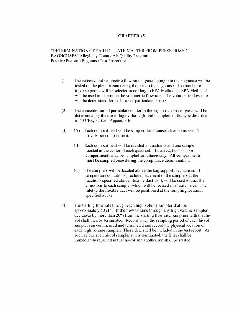
CHAPTER 45
"DETERMINATION OF PARTICULATE MATTER FROM PRESSURIZED
BAGHOUSES" Allegheny County Air Quality Program
Positive Pressure Baghouse Test Procedure
(1) The velocity and volumetric flow rate of gases going into the baghouse will be
tested on the plenum connecting the fans to the baghouse. The number of
traverse points will be selected according to EPA Method 1. EPA Method 2
will be used to determine the volumetric flow rate. The volumetric flow rate
will be determined for each run of particulate testing.
(2) The concentration of particulate matter in the baghouse exhaust gases will be
determined by the use of high volume (hi-vol) samplers of the type described
in 40 CFR, Part 50, Appendix B.
(3) (A) Each compartment will be sampled for 3 consecutive hours with 4
hi-vols per compartment.
(B) Each compartment will be divided in quadrants and one sampler
located at the center of each quadrant. If desired, two or more
compartments may be sampled simultaneously. All compartments
must be sampled once during the compliance determination.
(C) The samplers will be located above the bag support mechanism. If
temperature conditions preclude placement of the samplers at the
locations specified above, flexible duct work will be used to duct the
emissions to each sampler which will be located in a “safe” area. The
inlet to the flexible duct will be positioned at the sampling locations
specified above.
(4) The starting flow rate through each high volume sampler shall be
approximately 50 cfm. If the flow volume through any high volume sampler
decreases by more than 20% from the starting flow rate, sampling with that hi-
vol shall then be terminated. Record when the sampling period of each hi-vol
sampler run commenced and terminated and record the physical location of
each high volume sampler. These data shall be included in the test report. As
soon as one such hi-vol sampler run is terminated, the filter shall be
immediately replaced in that hi-vol and another run shall be started.
(5) Any gratings of the baghouse compartments that may admit outside air into
the baghouse will be sealed before the sampling period.
(6) Temperature of the gases leaving the baghouse compartment will be measured
by a temperature indicator located at each compartment being tested. This
indicator will be located in the vicinity of one of the high volume samplers
used to test the compartment.
(7) Moisture content of the gases going to the baghouse will be measured at the
plenum connecting the fans to the baghouse.
(8) Test high volume sampler mass concentrations results will be determined and
reported separately for each compartment.
(9) In determining compliance with the emissions limitations these steps will be
followed:
(A) A compartment average concentrations shall be computed by
arithmetically averaging the concentrations from the four hi-vol sampler
locations. If more than one run per hi-vol sampler is needed during any
3-hour test, then each of the individual concentrations per hi-vol sampler
shall first be flow weight averaged to determine a concentration for that
hi-vol sampler location.
(B) The separate compartment average concentrations shall be arithmetically
averaged to determine an overall concentration for the entire test.
(C) In computing compliance, the overall concentration determined in (B)
above shall be utilized, in conjunction with the flow rate measured.
PROCEDURE FOR QUALIFYING TEST HI-VOL
All test hi-vols used for testing pressurized baghouses should be qualified against a
properly calibrated Bureau hi-vol sampler. The concentration variation of all test hi-vol
samplers should indicate a concentration variation less than + 15% with the air quality
program hi-vol.
Qualification of test samplers will take place in a clean plant area with the hi-vols
placed at least 10 feet apart from each other and any other obstacles. Adequate power
service should be provided (115 v. @ approximately 100 amp.) to prevent low flow rates at
the individual samplers. Starting flow rates should be approximately 50 to 60 cfm. Final
flow reduction for each individual sampler should be less than 20%. Any sampler showing a
flow reduction greater than 20% should be recalibrated before the baghouse test is
performed.
The samplers will run for four hours. Flow rate readings will be taken at the start and
at one hour intervals during the test. Hi-vol filters will be supplied and weighed by the
Allegheny County Laboratory.

CHAPTER 46
"DETERMINATION OF VOLATILE ORGANIC COMPOUND CONTENT OF
EFFLUENT WATER"
Standard Methods for the Examination of Water from Wastewater, 14th edition, "Organic
Carbon (Total), Combustion - Infrared Method", American Public Health Association,
Washington, D.C.

CHAPTER 47
"DETERMINATION OF PARTICULATE MATTER FROM MODULAR BAGHOUSES",
Allegheny County Air Quality Program
Modular Baghouse Test Procedure
(1) Stack sampling procedures for determining compliance for sources equipped
the modular baghouses shall be the method set forth in chapter 5 of this
manual.
(2) If the baghouse contains more than five stacks, the averaging provisions shall
not apply and one test run per stack shall be performed. Compliance shall be
determined by (a) computing the mass emission rate, in lb. per hour, for each
stack and then (b) summing each of these mass emission rates. During all
sampling periods, the production rate shall be maintained within ten percent of
the mean rate for the entire sampling period.

CHAPTER 48
"MEASUREMENT OF ODOR EMISSIONS BEYOND SOURCE BOUNDARY LINES",
Allegheny County Health Department, Air Quality Program Methodology
Purpose:
This method shall be used to determine compliance with Section 2104.04 of Article
XXI, which prohibits the emission of malodorous matter that is perceptible beyond the
property line of the emitting source.
Observers:
During or immediately prior to making odor observations, the person making the
observation should not smoke, use tobacco, eat, drink or do anything that would significantly
affect his sense of smell. Observers should not wear aftershave, cologne or other products
having a significant odor.
Observations:
The following procedure shall be used insofar as possible in making odor
observations. Information concerning the results of the observation shall be recorded in a
form similar to that set forth in Appendix 1 attached hereto.
(1) Observer should first patrol the area near the source. If odors are detected, the
observer should immediately make an odor observation for approximately ten
minutes and record the information obtained on the observation form.
(2) The observer should then attempt to determine the source responsible for the
odors. This scan can be done by tracing the odor upwind or, if a particular
source is suspected, by going directly to that source. When the source is
identified, the observer should make another odor observation of
approximately ten minutes near the source boundary on the side on which the
initial odor observation was made. Information obtained should be recorded
on the observation form.
(3) If possible, the observer should then go to the opposite side of the source, make
an odor observation approximately 180o from the second observation point,
and record the information obtained.
(4) As time and circumstances permit, the observer should patrol the area around
the source to determine the extent of the area affected by the odors. Additional
observations can be made and recorded as described above.
(5) The observer may interview persons present in the area affected by the odors to
obtain background information. Relevant information includes the frequency
and duration of the odors, whether odor incidents occur at certain times or days
or under certain circumstances, the period over which odor incidents have
occurred, a description of the odors, their strength, characteristics and effects,
and the like.

Observation Forms:
Information for each observation should be recorded at the time of making the
observation.
A. Strength of Odors: The range of odor strengths observed at each observation
point should be recorded using the definitions set forth below. If one odor strength prevails,
that strength should be circled or otherwise marked to indicate that most of the odors during
the observation were of that strength.
No Odors:
Slight Odors: The level at which the odor becomes detectable and can be
described by its characteristics or can be distinguished from
other odors.
Moderate Odors: The level at which the odor becomes strong enough to block
out other odors, but is not so strong as to make someone try
to avoid the odor.
Strong Odors: The level at which a person would take positive action to
attempt to avoid the odor.
Very Strong Odors: The level at which the odor produces physiological effects,
such as nausea, difficulty of breathing, irritation of the eyes,
nose, or throat, or the level at which a residual smell
remains after the odor itself is gone.
B. Odor Description: The observer should describe as fully and objectively as
possible the odors perceived, including as appropriate comparisons to other commonly-
known odors. All physiological effects should be noted.
C. Weather Information: Should be obtained from a qualified meteorologist or from
the National Weather Service. Any significant differences between actual weather
conditions at the observation sites and the information obtained from such meteorologist
should be noted on the observation form.
D. Map: The observation form should include a hand-drawn map showing all
observation points, their approximate distance from the suspected source, wind direction as
perceived at each observation point, other area odor sources, relevant topographical features
and other pertinent information.

APPENDIX 1
ALLEGHENY COUNTY HEALTH DEPARTMENT
AIR QUALITY PROGRAM
ODOR OBSERVATION FORM
DATE: SOURCE:
DAY:
OBSERVATION START: AM/PM OBSERVATION COMPLETE: AM/PM
ODOR STRENGTH WEATHER CONDITIONS
WIND SPEED DIR:
TEMPERATURE: 0 = NONE
1 = SLIGHT
2 = MODERATE
3 = STRONG
4 = VERY STRONG
OBSERVATION TIME ODOR MIN. OD@ ODOR
STATION INTERVAL STRENGTH EA. STRENGTH TYPE
TOTAL MINUTES OF OBSERVATION:
TOTAL MINUTES OF ODOR DETECTION:
OBSERVER:
SIGNATURE:
STATIONS LOCATIONS:
Remarks:
PELASE SKETCH AREA AND STATION LOCATIONS ON BACK
Odor Verified by Citizen Witness: Yes No
Signature of Citizen Witness:

CHAPTER 49
"DETERMINATION OF SULFUR IN COKE"
"Standard Test Method for Total Sulfur in the Analysis of Coal and Coke", American Society for
Testing Materials, D 3177, 1916 Race Street, Philadelphia, PA
CHAPTER 50
CALIBRATION AND MAINTENANCE Of Sampling Equipment Shall be Performed According
to: Jerome J. Rom, Maintenance, Calibration and Operation of Isokinetic Source Sampling
Equipment, Environmental Protection Agency, Research Triangle Park, N.C., APTD-0576,
March, 1972
High Volume Samplers used to determine particulate matter emissions from pressurized
baghouses pursuant to Chapter 45 shall be calibrated, maintained and operated according to
"Reference Method for the Determination of Suspended Particulates in the Atmosphere (High
Volume Method)", 40 CFR 60 Appendix B

CHAPTER 51
"MONITORING TEST METHODS FOR ABRASIVE BLASTING"

MONITORING TEST METHODS FOR ABRASIVE BLASTING
Parameter Method No. Method Name Comments
Lead CFR 40 Part 50
Appendix G
(EPA Method)
Reference Method
for the
determination of
lead in suspended
particulate matter
collected from
ambient air
8 Hours sampling or
longer
Free Silica
(Respirable
Fraction)
NIOSH Method
7500
Free Silica (Quartz,
Cristobalite,
Tridymite) in
atmospheric dust
8 Hours sampling or
longer
TSP CFR40 Part 50
Appendix B
(EPA Method)
Reference method
for the
determination of
suspended
particulate matter in
the atmosphere
(high-volume
method)
8 Hours sampling or
longer
PM-10* (EPA method)
CFR40 Part 50
Appendix J as
proposed in FR Vol.
49, No. 55 Tuesday,
March 20, 1984
Optional method for
PM10 NIOSH
method 7500
Reference method
for the
determination of
particulate matter as
PM10 in the
atmosphere
Personal pump
sampling for PM10
using a 37 mm PVC
filter and a MSA
nylon cyclone (Part
No. 456228) to
fractionate the
particles
8 Hours sampling or
longer
Quartz filters meet
EPA specifications
for SSI PM 10
Samplers
8 Hours sampling
for longer. High
volume respirable
dust sample
(sampling rate of
9L/min.)
* PM-10 sampling is not required for abrasive blasting monitoring

CHAPTER 52
"METHODS FOR WASTE DERIVED LIQUID FUEL SPECIFICATION AND FLUE GAS
ANALYSIS"
I. Sampling for Waste Derived Liquid Fuel Specification Analysis:
1. Sampling
a. For a tank with a capacity of 1,000 gallons or less, a
representative sample of waste-derived liquid fuel shall consist
of at least a single sample of sufficient volume and weight for
all analyses required by Section 2105.31 of Article XXI. Single
samples shall be taken from the tank at a level of fifty percent
(50%) of the liquid height from the bottom of the tank.
b. For a tank with a capacity of greater than 1,000 gallons, a
representative sample of waste-derived liquid fuel shall consist
of a composite sample taken in a manner acceptable to the
Director. A single sample taken in accordance with
Subparagraph a. of this Paragraph shall constitute a composite
sample only where the owner or operator of the waste-derived
liquid fuel-burning operation can demonstrate to the Director’s
satisfaction that the contents of the tank were sufficiently
agitated prior to and during the taking of the sample.
II. Equipment Testing by Direct Emission Reduction for the Waste-Derived Liquid Fuel Regulation:
1. For all equipment except equipment subject to §2105.31.a.4, Article XXI, direct
emission reduction shall be determined by the following equation:
CO2
Percent Direct Emission Reduction = CO+CO2 x 100,where:
a. CO2 = the proportion by volume of carbon dioxide (CO2) in the flue
gas (on a dry basis); and
b. CO = the proportion by volume of carbon monoxide (CO) in the flue
gas (on a dry basis).
2. For equipment subject to §2105.31.a.4 of Article XXI, direct emission reduction
shall be determined by one (1) of the following equations:
CC14 (in) - CC14 (out)
a. Percent Direct Emission Reduction = CC14 (in) x100, where:
i. CC14 (in) = the mass feed rate of carbon tetrachloride
(CC14) going into the equipment in the fuel;
ii. CC14 (out) = the mass emission rate of carbon
tetrachloride ( CC14 ) coming from the equipment in
the flue gas; and
iii. The fuel being burned for the purpose of determining
direct emission reduction under this Subparagraph, in
addition to complying with Paragraph #3 of Section
2105.31. This test procedure is spiked so as to contain
at least 1,000 ppm of carbon tetrachloride (CC14) by
weight.

POHC (in) - POHC (out)
b. Percent Direct Emission Reduction = POHC (in) x 100, where:
I. POHC (in) = the mass feed rate of principal organic
halogenated compounds (POHC) going into the
equipment in the fuel;
ii. POHC (out) = the mass emission rate of principal
organic halogenated compounds (POHC) coming from
the equipment in the flue gas; and
iii. The fuel being burned for the purpose of determining direct
emission reduction under this Subparagraph in addition to
complying with Paragraph #3 of Section 2105.31. This test
procedure is spiked so as to contain at least 1,000 ppm of
principal organic halogenated compounds (POHC) by weight.
3. For the purpose of determining direct emission reduction under Section 2105.31.:
a. The owner or operator of the affected equipment shall conduct the tests required
under testing requirements contained in Subsection §2108.02.e. of Article XXI
unless otherwise specified by this Section or the Director; and
b. The fuel being burned for a test required under Section 2105.31 shall:
I. Contain the maximum routine percentage of waste-derived
liquid fuel that is present when the equipment is operating at
routine operating conditions; and
ii. Contain waste-derived liquid fuel, which is representative of the
waste-derived liquid fuel burned when the equipment is
operating at routine operating conditions.

PARAMETER
Metals
(Ar,Cd,Cr,Ph)
METHOD NO.
1) ASTM D2788-72
2) NBS 1130 (1)
3) EPA Method 200.7
4) ASTM E 1097-86
5) APHA 305-85
6) APPHA 304-85
7) APA 303B
1)
(
METHOD NAME
Trace metals in gas turbine fuels (Atomic
absorption method)
Test procedures for three recycled fuel oil
impurities: Lead
Inductively coupled plasma-atomic emission
spectrometric method for trace element analysis of
water and wastes
Standard guide for direct current plasma emission
spectrometry analysis
Metals by emission spectroscopy using an
inductively coupled plasma source.
Determination of micro quantities of aluminum,
antimony, arsenic, barium, beryllium, cadmium,
chromium, cobalt, copper, iron, lead, manganese,
molybdenum, selenium, silver, and tin by
electrothermal atomic absorption spectrometry
Determination of low concentration of cadmium,
chromium, cobalt, copper, iron, lead, manganese,
nickel, silver, and zinc by chelation with
Ammonium Pyrrolidine Dithiocarbamate (APDC)
and extraction into Methyl Isobutyl Ketone (MIBK)
COMMENTS
Use with NJDEP digestion
procedures in Appendix C
Modified D2788 use with
nitric/perchloric acid digestion as
proposed in Engineering Science
Study
Appendix C to Part 136
Waste Water Method
Used by PTM inspectorate
Waste Water Method
Waste Water Method
Waste Water Method
C
C

PARAMETER
Metals
(Ar,Cd,Cr,Ph)
METHOD NO.
1) ASTM D2788-72
2) NBS 1130 (1)
3) EPA Method 200.7
4) ASTM E 1097-86
5) APHA 305-85
6) APHA 304-85
7) APA 303B
2
METHOD NAME
Trace metals in gas turbine fuels (Atomic
Absorption method)
Test procedures for three recycled fuel oil
impurities: Lead
Inductively coupled plasma-atomic emission
spectrometric method for trace element analysis of
water and wastes
Standard Guide for direct current plasma emission
spectrometry analysis
Metals by emission spectroscopy using an
inductively coupled plasma source
Determination of micro quantities of aluminum,
antimony, arsenic, barium, beryllium, cadmium,
chromium, cobalt, copper, iron, lead, manganese,
molybdenum, selenium, silver, and tin by
electrothermal atomic absorption spectrometry
Determination of low concentration of cadmium,
chromium, cobalt, copper, iron, lead, manganese,
nickel, silver, and zinc by chelation with
Ammonium Pyrrolidine Dithiocarbamate (APDC)
and extraction into Methyl Isobutyl Ketone (MIBK)
COMMENTS
IsUse with NJDEP digestion procedures
in Appendix C
MModified D2788 use with
nitric/perchloric acid digestion as
proposed in Engineering Science Study.
AAppendix C to Part 136 Waste Water
MMethod
UUsed by PTM inspectorate
Waste Water Method
Waste Water Method
Waste Water Method

PARAMETER
PCB’s
BOTTOM SEDIMENT
AND WATER
WATER ONLY
SEDIMENT ONLY
ASH
METHOD NO.
1)--------------------------------
2) NBS 584 (2)
3) ASTM D4059-86
1) ASTM D 96-73
2) ASTM D 1796-83
3) ASTM D 95-83
4) ASTM D 473-81
ASTM D 874-82
ASTM D 482-80
METHOD NAME
Improved method for polychlorinated biphenyl
determination in complex matrices (1)
Determination of polychlorinated biphenyls in
waste and lubricating oils
Analysis of polychlorinated biphenyls in
insulating liquids by gas chromatography
Water and sediment in crude oils
Water and sediment in fuel oils by the
Centrifuge method
Water in petroleum products and Bituminous
material by distillation
Sediment in crude oils and fuel oils by the
extractive method
Sulfated ash from lubricating oils and
additives
Ash from petroleum products
COMMENTS
EPA 608 used as framework (waste
water method) Digestion of sample
according to Copeland and Gohmann
procedure.
Utilized L C clean-up procedure
followed by glass capillary GC method
with electron capture detector.
Requires sample pre-clean up by
NBS584 or Copeland and Gohmann
procedure (used by PTM inspectorate)
Centrifuge method recommended by
NBS 1130 for analysis of difficult
types of oils.
Distillation method.
Extraction method
Sulfated ash
Method is limited to petroleum
products which are free from added ash
forming additives, including certain
phosphorus compounds.
(1) Copeland G.B. and Gohman, C.S., “Improved Method for Polychlorinated Biphenyl Determination in Complex Matrices”, Environmental Science
and Technology
(2) NBS Special Publication 58

METHODS FOR WASTE DERIVED LIQUID FUEL SPECIFICATION ANALYSIS, ANALYSIS BY WEIGHT
PARAMETER METHOD NO. METHOD NAME COMMENTS
FLASH PIONT ASTM D 93-85 Flash point by Pensky-Martens closed tester
TOTAL HALOGENS 1) ASTM D 808-81 Chlorine in new and used petroleum (bomb method)
2) ASTM D 1317-83 Chlorine in new and used lubricants (Sodium Alcoholate
method.
3) ------------------------- X-Ray fluorescence or ion chromatography by ASTM
D 808-63
HEAT OF COMBUSTION 1) ASTM D 240-85 Heat of combustion of liquid hydrocarbon fuels by bomb
Calorimeter
2) NBS 1130 Heating value
METHODS FOR FLUE GAS ANALYSIS APPLICABLE
TO WASTE-DERIVED LIQUID FUEL REGULATION
A. Methods for Carbon Monoxide Analysis:
1) EPA method 10 – analysis using a luft-type NDIR analyzer or
equivalent. This method allows either a continuous or integrated
approach; the modification of the integrated approach using EPA
method 25 sample collection tanks instead of tedlar bags allows
safe storage of the undegraded CO sample to the laboratory for
analysis.
2) ASTM D 1946-77 (uses thermal conductivity detector)
B. Methods for Carbon Dioxide Analysis:
1) EPA Method 3 (orsat or fyrite methods)
2) EPA Method 3A (instrument method) – concurrent measurements
should be obtained using orsat or fyrite analyzers, instrument
specifications are contained in Method 6C
3) EPA Method 6A (method 6 midget impinger train followed by
ascarite II CO2 absorber); acceptable for CO2 values between
2.5% and 25%.
C. Methods for Principal Organic Halogenated Compound Analysis:
1) EPA Method 23 (determination of halogenated organics) – For
analysis, gas chromatographic (GC) analysis using either a flame
ionization detector (FID) or electron capture detector (EDC) is
acceptable to the Administrator.
CHAPTER 53
“DETERMINATION OF INHALABLE FUGITIVE PARTICULATE EMISSIONS
FROM AIR POLLUTION SOURCES WITHIN A STRUCTURE,” Allegheny County
Air Quality Program Methodology

CHAPTER 53
DETERMINATION OF INHALABLE FUGITIVE PARTICULATE EMISSIONS FROM AIR
POLLUTION SOURCES WITHIN A STRUCTURE
Principle and Applicability and Limitations:
a. The method measures the mass concentration of respirable dust smaller
than 10 micron particulate size.
b. This method is applicable to respirable dust from the fugitive emission
sources enclosed within a structure.
c. Depending on predominant wind direction during the sampling, air flow
will be inward at some openings and outward at others. Only the openings
with outward air flow ill be responsible for fugitive emission and
therefore, the area and air velocity through these openings will be taken
into consideration for calculating emission rate.
d. Since the wind direction may change during sampling, the air flow which was outward
may become inward at the same openings where the test is being carried out. Under this
situation, the sampling must continue at the same opening.
If the air flow remains inward for more than 50 percent of sampling time, then the
sample must be discarded and another opening should be selected for sampling.
A. Sample Points:
By visual determination, select the openings with the most fugitive dust leakage out of
enclosed structure.
Each sampling area should be divided into 23 equal areas with the sample point at the
centroid of each area.
B. Velocity and Temperature:
The velocity of the air flowing through the sample point can be measured with a vane
anemometer or Kurtz Model 441 or equivalent at the centroid of the sample point. The
velocity should be measured at the beginning and end of the sampling period for each
sample point. The total of 24 velocity measurements shall be made per two hour run.
The temperature of the air can be measured with a mercury thermometer before and
after each test run.

C. Moisture:
The moisture in the sampled air will be the relative humidity of the ambient air. This
can be determined with a sling psychrometer and should be measured at least once at
each opening.
D. Area of Openings:
The area of every opening shall be measured in square feet.
1.0 Apparatus:
1.1 Sampling train: The sample train consists of a 10 millimeter Dorr-
Oliver cyclone connected to a filter holder (37mm) loaded with a tared
quartz filter and personal sampling pump.
I.I.I. Personal sampling pump: A personal sampling pump
capable of sampling air at 1.7L/min +5% with flexible
Tygon connecting tubing.
I.I.2. Filter: Whatman type ZM-A, 37 mm diameter quartz
filter or equivalent supported with backup pad in a two-
piece, 37mm cassette filter holder held together by tape or
cellulose shrink band.
I.I.3. Cyclone: 10 mm Dorr-Oliver nylon cyclone.
I.I.4. Sampling Head Holder: This holder must keep the
cassette, cyclone and coupler together rigidly so that air
enters only at the cyclone inlet.
2.0 Equipment for Analysis:
2.1 Environmental Chamber for Balance: It shall be maintained at 20
degrees C + 0.3 degrees C and 50% + 5% humidity.
2.2 Vacuum desiccator:
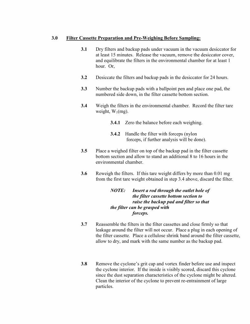
3.0 Filter Cassette Preparation and Pre-Weighing Before Sampling:
3.1 Dry filters and backup pads under vacuum in the vacuum desiccator for
at least 15 minutes. Release the vacuum, remove the desiccator cover,
and equilibrate the filters in the environmental chamber for at least 1
hour. Or,
3.2 Desiccate the filters and backup pads in the desiccator for 24 hours.
3.3 Number the backup pads with a ballpoint pen and place one pad, the
numbered side down, in the filter cassette bottom section.
3.4 Weigh the filters in the environmental chamber. Record the filter tare
weight, W1(mg).
3.4.1 Zero the balance before each weighing.
3.4.2 Handle the filter with forceps (nylon
forceps, if further analysis will be done).
3.5 Place a weighed filter on top of the backup pad in the filter cassette
bottom section and allow to stand an additional 8 to 16 hours in the
environmental chamber.
3.6 Reweigh the filters. If this tare weight differs by more than 0.01 mg
from the first tare weight obtained in step 3.4 above, discard the filter.
NOTE: Insert a rod through the outlet hole of
the filter cassette bottom section to
raise the backup pad and filter so that
the filter can be grasped with
forceps.
3.7 Reassemble the filters in the filter cassettes and close firmly so that
leakage around the filter will not occur. Place a plug in each opening of
the filter cassette. Place a cellulose shrink band around the filter cassette,
allow to dry, and mark with the same number as the backup pad.
3.8 Remove the cyclone’s grit cap and vortex finder before use and inspect
the cyclone interior. If the inside is visibly scored, discard this cyclone
since the dust separation characteristics of the cyclone might be altered.
Clean the interior of the cyclone to prevent re-entrainment of large
particles.

3.9 Assemble the sampler head. Check alignment of filter holder and
cyclone in the sampling head to prevent leakage.
4.0 Procedure
4.1 Calibration
4.1.1. Calibrate each personal sampling pump to
1.7 L/min. With a representative quartz
filter in line.
4.2 Sampling Procedure
4.2.1. For door or window openings, sample at the
centroid of each 12 equal areas used during
the velocity traverse for 10 minutes per
point for a total of 120 minutes per run.
The sample flow rate shall be 1.7 L/min.
Three runs shall comprise a test, one each at
three different window or door openings.
The cyclone air intake shall face the window
or door opening and shall be no more than 6
inches outside the plane of the door or the
window.
NOTE: Do not allow the sample assembly
to be inverted at any time.
Turning the cyclone to anything
more than a Horizontal
orientation may deposit oversized
material from the cyclone body
onto the filter.
5.0 Sample Preparation
5.1 Wipe dust from the external surface of the filter cassette with a moist
paper towel to minimize contamination. Discard the paper towel.
5.2 Remove the top and bottom plugs from the filter cassette. Place the filter
cassettes in a vacuum desiccator for at least 15 minutes followed by
equilibration for at least 1 hour in the environmental chamber, or
desiccate the filter in desiccator for 24 hours.

5.3 Remove the filter cassette band, pry open the filter cassette, and remove
the filter by inserting a rod in the outlet hole of the filter cassette. Handle
the filters very carefully be the edge to avoid loss of dust.
5.4 Zero the microbalance before all weighings. Use the same microbalance
for weighing filters before and after sample collection. Calibrate the
balance with National Bureau of Standards Class M. Weights.
5.5 Take two replicate blank filters for every batch of field samples for
quality assurance on the sampling procedures. The set of replicate blank
filters should be exposed to the same dust environment, either in a
laboratory dust chamber or in the field. The quality control samples must
be taken with the same equipment, procedures and personnel used in the
routine field procedures. Circulate precision from these replicates. Take
corrective action when the precision is out of control.
5.6 Weigh each filter, including field blanks. Record this post-sampling
weight, W2(mg), beside its corresponding weight. Record anything
remarkable about a filter (e.g., visible particulates, overloaded, leaking,
wet, torn, etc.)
6.0 Calculations
6.1 Calculate the concentration of respirable dust, C (mg/m3), in the air
volume sampled, V (liters):
C=(W2-W1) + B . 103, mg/m
3 (1)
V
Where: W1= tare weight of filter before sampling (mg).
W2= post-sampling weight of sample-containing
Filter (mg).
B = mean change in field blank filter weights
between tare and post-sampling (mg) (+or-)
V = Air volume sampled (liters)
6.2 Calculation of Air Volume rate through a door or window.
V0s=Vs x As (2)
Where: V0s = Volumetric flow rate from a single window
or door opening of ft3/min.
Vs = Average of 24 velocity measurements by
anemometer (ft/min) for a single window or door
opening.

As = Cross-sectional area of a single window or
ft2 door opening.
6.3 Calculation of Total Air Volume rate through the building.
V01 = Vϖ = A1 (3)
Where: V01 = Total volumetric outward flow rate
from all building openings (ft3/min).
Vϖ = Opening velocity averaged for 3 runs
(ft/min).
A1 = Cross sectional area (ft2) of all building
openings where air flow was outwards.
6.4 Emission Rate Calculation ( 1 lb/hour )
C = 1.3216 x 10⁴Cavg x VO (4)
3.53
Where: C = Total concentration lb/hour from all openings.
Cavg = Average concentration mg/m3 of 3 runs at
3 different openings.
Cavg = (C1 + C2 + C3) /3
C1 = Concentration from run 1 mg/m3
C2 = Concentration from run 2 mg/m3
V01 = Total volumetric flow rate from all building
openings. Ft3
min.
35.3 = Conversion factor for converting cubic feet
to cubic meters.
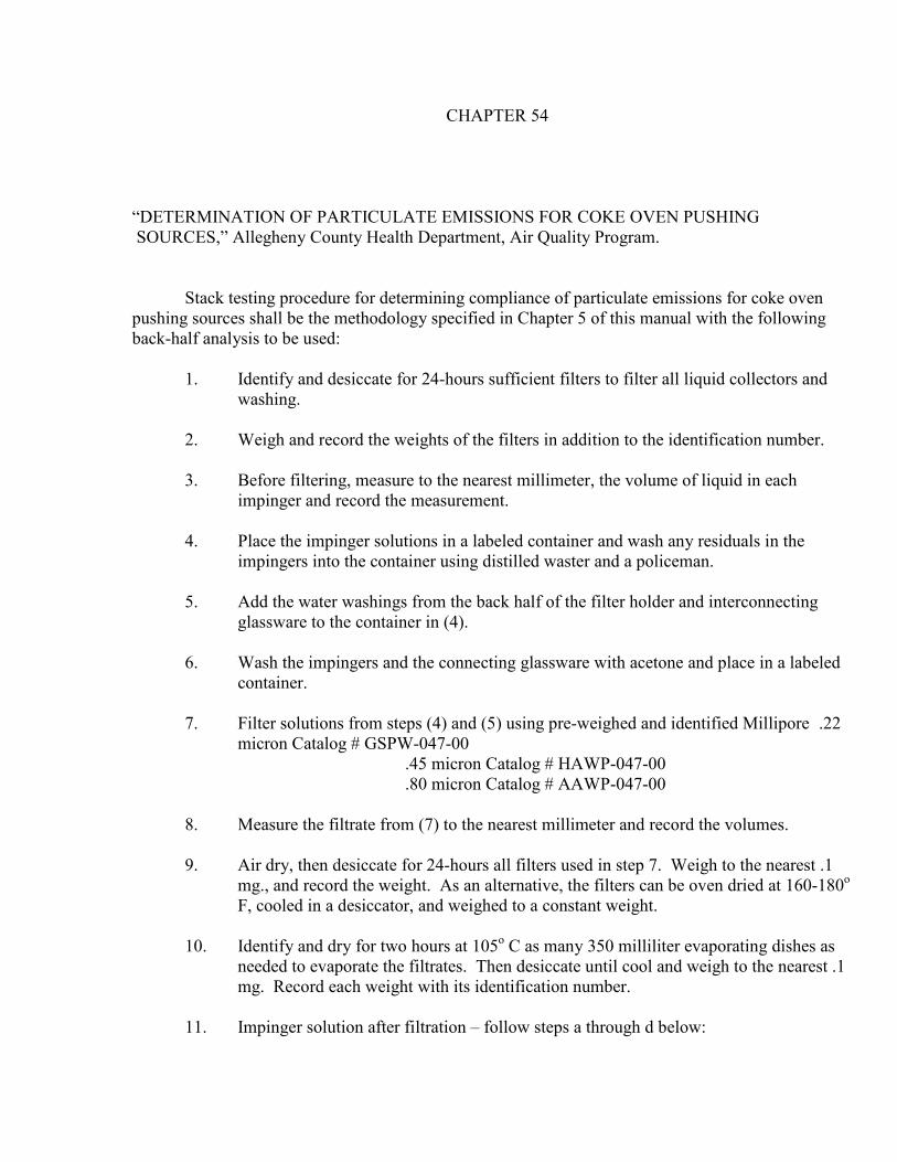
CHAPTER 54
“DETERMINATION OF PARTICULATE EMISSIONS FOR COKE OVEN PUSHING
SOURCES,” Allegheny County Health Department, Air Quality Program.
Stack testing procedure for determining compliance of particulate emissions for coke oven
pushing sources shall be the methodology specified in Chapter 5 of this manual with the following
back-half analysis to be used:
1. Identify and desiccate for 24-hours sufficient filters to filter all liquid collectors and
washing.
2. Weigh and record the weights of the filters in addition to the identification number.
3. Before filtering, measure to the nearest millimeter, the volume of liquid in each
impinger and record the measurement.
4. Place the impinger solutions in a labeled container and wash any residuals in the
impingers into the container using distilled waster and a policeman.
5. Add the water washings from the back half of the filter holder and interconnecting
glassware to the container in (4).
6. Wash the impingers and the connecting glassware with acetone and place in a labeled
container.
7. Filter solutions from steps (4) and (5) using pre-weighed and identified Millipore .22
micron Catalog # GSPW-047-00
.45 micron Catalog # HAWP-047-00
.80 micron Catalog # AAWP-047-00
8. Measure the filtrate from (7) to the nearest millimeter and record the volumes.
9. Air dry, then desiccate for 24-hours all filters used in step 7. Weigh to the nearest .1
mg., and record the weight. As an alternative, the filters can be oven dried at 160-180o
F, cooled in a desiccator, and weighed to a constant weight.
10. Identify and dry for two hours at 105o C as many 350 milliliter evaporating dishes as
needed to evaporate the filtrates. Then desiccate until cool and weigh to the nearest .1
mg. Record each weight with its identification number.
11. Impinger solution after filtration – follow steps a through d below:

a. Evaporate impinger (sample) solution to a minimum weight using evaporating
dishes prepared in step 10 and an equal amount of distilled water used in the
impingers at 160180o F. Record the weight of the distilled water residue. This
will be the distilled water blank.
b. Re-dissolve the sample solution residue in water and neutralize using NaOH
used. Calculate weight of Na + ion. (The NaOH should react with any free H2
SO4 to tie up the SO4 = present in sample as well as other condensibles).
c. Evaporate neutralized solution to constant weight at 160-180o F. Record the
weight. (This weight should include NA +, added plus the SO4 = present in
sample, as well as other condensibles).
d. Re-dissolve in distilled water and use turbidimetric method for determination of
sulfate ion (SO4=). Calculate weight of SO4=. An acceptable alternative for
determining sulfate ion would be the Barium-Thorninn titration method (EPA
Method 6).
12. Transfer the acetone washing from step 6 into a pre-weighed evaporating dish after
measuring and recording the volume of acetone.
13. Place a measured quantity of unused acetone into pre-weighed evaporating dish. This is
the acetone blank.
14. Evaporate both blank (13) and unknowns (12) at less than 60o C. in a vacuum.
15. Dessicate to a constant weight and reweigh. Then record the weight to the nearest
0.1milligram.
16. Calculation of back half particulate catch – determine the total back half particulate
catch from the sum of the weights obtained from steps (9), (11c), and the unknown in
step (15) minus the weights obtained from steps (11a), (11b), and (11d), and the blank
from step (15).
Compliance with the particulate mass emission standard for coke oven pushing shall be
calculated based upon the front half of the EPA train and insoluble weights in the impinger
solution and on sample exposed surfaces subsequent to the final filtration media. Insoluble
weights shall be determined by 0.22 micron filtration

CHAPTER 55
“DETERMINATION OF VOLATILE ORGANIC COMPOUND EMISSIONS FROM VAPOR
RECOVERY SYSTEMS FOR GASOLINE LOADING OPERATIONS”
Emission Test Procedures for Tank Truck Gasoline Loading Terminals (Appendix A) “Control of
Hydrocarbons from Tank Truck Gasoline Loading Terminals,” EPA-450/2-77-026 United States
Environmental Protection Agency, Oct. 1977.

CHAPTER 56
“DETERMINATION OF THE LEAKA TIGHTNESS OF GASOLINE TANK TRUCKS AND
VAPOR RECOVERY SYSTEMS”
Pressure-Vacuum Test Procedures for Leak Tightness of Truck Tanks (Appendix A), “Control
of Volatile Organic Compound Leaks From Gasoline Tank Trucks and Vapor Collection
Systems,” EPA-450/2-78-051, United States Environmental Protection Agency, December,
1978.

CHAPTER 57
“DETERMINATION OF THE MAGNITUDE OF LEAKS OF VOLATILE ORGTANIC
COMPOUNDS FROM GASOLINE TANK TRUCKS AND VAPOR RECOVERY
SYSTEMS”
Gasoline Vapor Leak Detection Procedure by Combustible Gas Detector (Appendix B),
“Control of Volatile Organic Compound leaks from Gasoline Tank Trucks and Vapor
Collection Systems,” EPA-450/2-78-051, United States Environmental Protection Agency,
December, 1978.

CHAPTER 58
“DETERMINATION OF COMPLIANCE OF PERCHLOROETHYLENE DRY CLEANING
FACILITIES”
Appendix V, “Compliance Test Method and Leak Detection Equipment for Perchloroethylene
Dry Cleaners,” Measurement of Volatile Organic Compounds, United States Environmental
Protection Agency, EPA-450/2-78-041, Washington, D.C.

CHAPTER 59
“DETERMINATION OF COMPLIANCE OF PETROLEUM SOLVENT DRY CLEANING
FACILITIES EMPLOYING A PETROLEUM SOLVENT FILTRATION SYSTEM BUT NOT
EMPLOYING CARTRIDGE FILTERS”
ASTM Method D322-901 (Standard Test Method for Gasoline Diluents in Used Gasoline
Engine Oils by Distillation).

CHAPTER 60
“DETERMINATION OF ASBESTOS CONTENT OF BULK SAMPLES”
“Guidance for Controlling Asbestos-Containing Materials In Buildings,” EPA 560/5-85-024
United States Environmental Protection Agency, June 1985.
CHAPTER 101
“DETERMINATION OF PARTICULATE AND GASEOUS MERCURY EMISSIONS FROM
CHLOR-ALKALI PLANTS (AIR STREAMS),” United States Environmental Protection
Agency, 40 CFR 61 Appendix B (Method 101 and 101A)

CHAPTER 102
“DETERMINATION OF PARTICULATE AND GASEOUS MERCURY EMISSIONS FROM
CHLOR-ALKALI PLANTS (HYDROGEN STREAMS),” United States Environmental
Protection Agency, 40 CFR 61 Appendix B (METHOD 102)

CHAPTER 103
“BERYLLIUM SCREENING METHOD,” United States Environmental Protection Agency, 40
CFR 61 Appendix B (METHOD 103)

CHAPTER 104
“DETERMINATION OF BERYLLIUM EMISSIONS FROM STATIONARY SOURCFES,”
United States Environmental Protection Agency, 40 CFR 61 Appendix B (METHOD 104)

CHAPTER 105
“METHOD FOR DETERMINATIN OF MERCURY IN WASTE WATER TREATMETN
PLANT SEWAGE SLUDGE,” United States Environmental Protection Agency, 40 CFR 61
Appendix B (METHOD 105)

CHAPTER 106
“DETERMINATION OF VINYL CHLORIDE FROM STATIONARY SOURCES,” United
States Environmental Protection Agency, 40 CFR 61 (Appendix B (Method 106)

CHAPTER 107
“DETERMINATION OF VINYL CHLORIDE CONTENT OF INPROCESS WASTES,
WATER SAMPLES, AND VINYL CHLORIDE CONTENT OF POLYVINYL CHLORIDES
IN, SLURRY, WETCAKE AND LATEX SAMPLES,” United States Environmental Protection
Agency, 40 CFR 61 Appendix B (METHOD 107 and 107A)

CHAPTER 108
“DETERMINATION OF PARTICULATE AND GASEOUS ARSENIC EMISSIONS,” United
States Environmental Protection Agency, 40 CFR 61 Appendix B (METHOD 108 and 108A)

CHAPTER 109
“DETERMINATION OF VISIBLE EMISSIONS FROM COKE OVEN BATTERIES,” United
States Environmental Protection Agency, 40 CFR 61 (Appendix B (Method 109), as modified
by the Allegheny County Health Department, Air Quality Program.
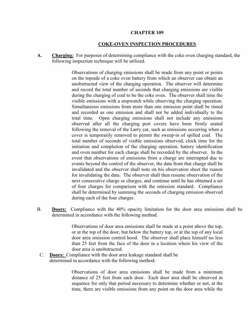
CHAPTER 109
COKE-OVEN INSPECTION PROCEDURES
A. Charging: For purposes of determining compliance with the coke oven charging standard, the
following inspection technique will be utilized.
Observations of charging emissions shall be made from any point or points
on the topside of a coke oven battery from which an observer can obtain an
unobstructed view of the charging operation. The observer will determine
and record the total number of seconds that charging emissions are visible
during the charging of coal to be the coke oven. The observer shall time the
visible emissions with a stopwatch while observing the charging operation.
Simultaneous emissions from more than one emission point shall be timed
and recorded as one emission and shall not be added individually to the
total time. Open charging emissions shall not include any emissions
observed after all the charging port covers have been firmly seated
following the removal of the Larry car, such as emissions occurring when a
cover is temporarily removed to permit the sweep-in of spilled coal. The
total number of seconds of visible emissions observed, clock time for the
initiation and completion of the charging operation, battery identification
and oven number for each charge shall be recorded by the observer. In the
event that observations of emissions from a charge are interrupted due to
events beyond the control of the observer, the data from that charge shall be
invalidated and the observer shall note on his observation sheet the reason
for invalidating the data. The observer shall then resume observation of the
next consecutive charge or charges, and continue until he has obtained a set
of four charges for comparison with the emission standard. Compliance
shall be determined by summing the seconds of charging emission observed
during each of the four charges.
B. Doors: Compliance with the 40% opacity limitation for the door area emissions shall be
determined in accordance with the following method.
Observations of door area emissions shall be made at a point above the top,
or at the top of the door, but below the battery top, or at the top of any local
door area emission control hood. The observer shall place himself no less
than 25 feet from the face of the door in a location where his view of the
door area is unobstructed.
C. Doors: Compliance with the door area leakage standard shall be
determined in accordance with the following method:
Observations of door area emissions shall be made from a minimum
distance of 25 feet from each door. Each door area shall be observed in
sequence for only that period necessary to determine whether or not, at the
time, there are visible emissions from any point on the door area while the

observer walks along side of the battery. If the observer’s view of a door
area is more than momentarily obstructed, as, for example, by door
machinery, pushing machinery, coke guide, Luther truck, or opaque steam
plumes, he shall record the door area obstructed and the nature of the
obstruction and continue the observations with the next door area in
sequence which is not obstructed. The observer shall continue this
procedure along the entire length of the battery for both sides and shall
record the battery identification, battery side, and oven door identification
number of each door area exhibiting visible emissions. Before completing
the traverse or immediately thereafter he shall attempt to re-observe the
obstructed doors. Compliance with this section shall be calculated by
application of the following formula, which excludes two door areas
representing the last oven charged from the numerator and obstructed door
areas from the denominator:
(# of door areas with visible emission) -2 x100=10% or less.
(# of door areas on operating ovens in battery) - (#of door areas obstructed
from view)
D. Charging Ports: For purposes of determining compliance with the
percent charging port leakage standard, observations of any visible
emissions from coke oven topside, other than charging or pushing
emissions, shall be made and recorded during the time an observer walks
the topside of a battery from one end to the other. Each oven shall be
observed in sequence. The observer shall record the battery
identification, the points of topside emissions from each oven, and the
oven number, and whether an oven was dampered off. Compliance shall
be determined by application of the following formula:
(#of charging ports with visible emissions) x(100)=2% or less.
(# of charging ports on operating ovens)
E. Offtake Piping:
For purposes of determining compliance with the percent off take piping leakage
standard, observations of any visible emissions from the off take piping shall be made
by traversing the topside of the battery near the centerline. During the traverse, the
observer may stray from near the centerline of battery and walk as close as possible to
the offtake piping to determine whether an observed emission is emanating from the
offtake piping. The observer shall traverse the battery once per each collector main.
Therefore, to observe a battery with two collector mains, one observer may traverse
the battery in one direction for one offtake system and traverse the battery in one
direction for the second offtake system or two observers can traverse the battery in
one direction. Each oven shall be observed in sequence. The observer shall record
the battery identification, the points of offtake piping emission from any oven and the

oven number. Compliance shall be determined by application of the following
formula:
(# of offtake piping with visible emissions x (100) = 5% or less.
(# of offtake piping on operating ovens)
F. Pushing: Compliance with the visible emission standards for pushing shall be
determined in accordance with the following methods:
(1) Visible emission observers shall be certified in accordance with the
procedures specified at 40 C.F.R. Part 60 Appendix A. Method 9.
(2) The provisions of Method 9 Section 2.5 shall not apply in that
averaging shall not be used to determine compliance with the visible
emissions performance standards.
(3) In making observations of any pushing emissions control device outlet
the observer shall be positioned in accordance with the provisions of
Section 2.1 of Method 9 except that if it is an overcast day and the
reader need not position himself with his back to the sun.
(4) In viewing the pushing operation the observer shall stand on the coke
side of the battery where a clear view of the push can be obtained.
This generally should be a location on the ground, in the coke side
yard, outside the hot car tracks approximately perpendicular to the
observed oven. However, the observer is not restricted to the ground
level, but may make the observation from some elevated level. If it is
an overcast day or if the plume is in a shadow, the reader need not
follow the requirements about positioning his back to the sun.
(5) During the pushing operation, the reader shall observe all the pushing
emissions including, but not limited to, fugitive emissions from the
pushing emission control device and from open quench cars during
travel.
(6) Except as provided in paragraph (7) below, the reader upon observing
any visible emissions with opacity equal to or greater than 20%
opacity, as determined against any contrasting background, shall start
an accumulating stopwatch. The reader shall stop the watch whenever
the visible emissions are less than 20% opacity. Observations shall not
be made until the coke side door machine is in the final spotted
position and ready to receive coke at the oven to be pushed. The
reader continues this procedure for the entire pushing operation. The
reader shall independently observe emission from the pushing
emission control device gas cleaning outlet and fugitive emissions
form the pushing operation.

(7) Pushing emissions during the transport of coke to quench tower shall
be evaluated separately. In this case, the readers shall be positioned in
accordance with paragraph 4 above.
G. Combustion Stacks: Compliance with the visible emission standard for
combustion stacks shall be determined in accordance with the provisions
of chapter 9.
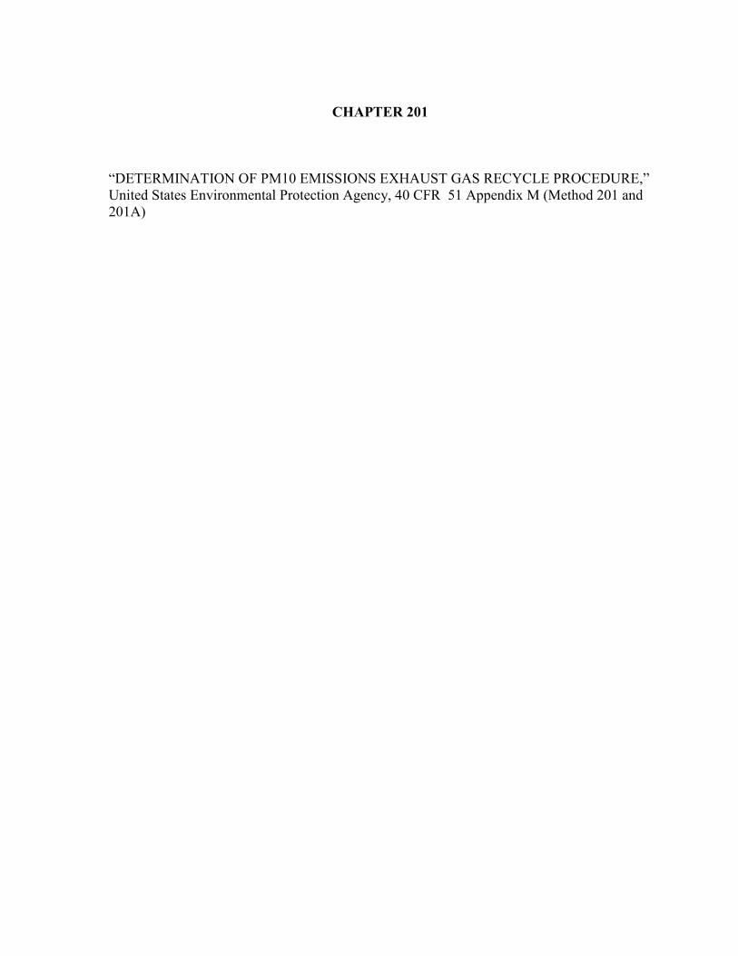
CHAPTER 201
“DETERMINATION OF PM10 EMISSIONS EXHAUST GAS RECYCLE PROCEDURE,”
United States Environmental Protection Agency, 40 CFR 51 Appendix M (Method 201 and
201A)

CHAPTER 202
“DETERMINATION OF CONDENSIBLE PARTICULATE EMISSIONS FROM
STATIONARY SOURCES,” United States Environmental Protection Agency, 40 CFR 51
Appendix M (Method 202)
CHAPTER 205
“VERIFICATION OF GAS DILUTION SYSTEMS FOR FIELD INSTRUMENT
CALIBRATIONS,” United States Environmental Protection Agency, 40 CFR 51 Appendix
M (Method 202)


CHAPTER 303
“DETERMINATION OF VISIBLE EMISSINS FROM COKE OVEN BATTERIES,”
United States Environmental Protection Agency, 40 CFR 61 Appendix A (Method 303 thru
303A)

APPENDIX A
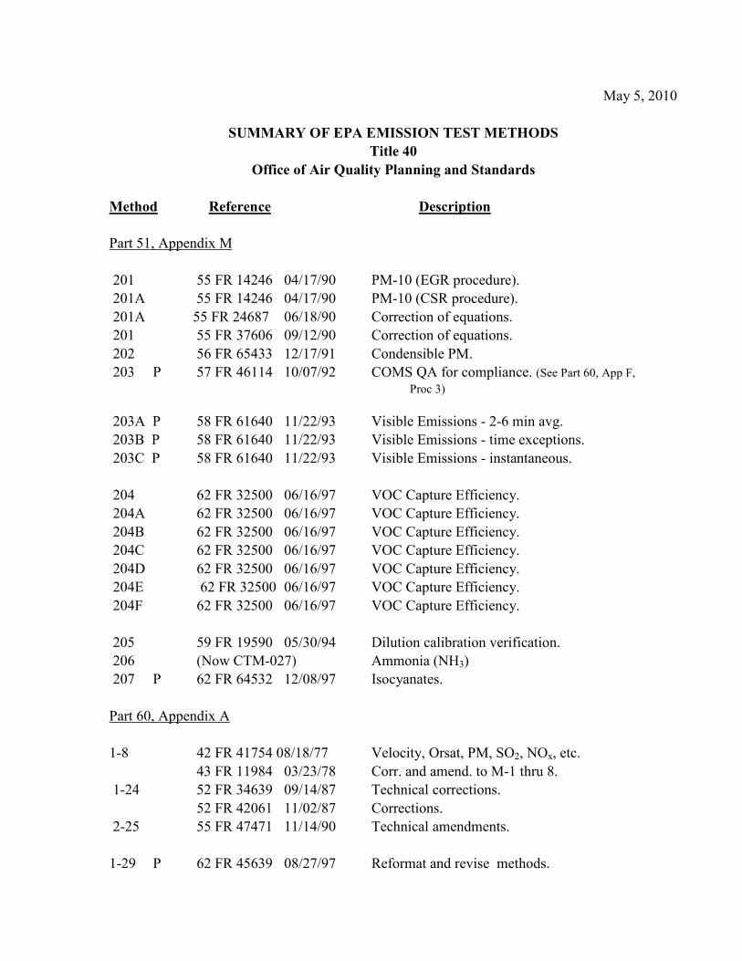
May 5, 2010
SUMMARY OF EPA EMISSION TEST METHODS
Title 40
Office of Air Quality Planning and Standards
Method Reference Description
Part 51, Appendix M
201 55 FR 14246 04/17/90 PM-10 (EGR procedure).
201A 55 FR 14246 04/17/90 PM-10 (CSR procedure).
201A 55 FR 24687 06/18/90 Correction of equations.
201 55 FR 37606 09/12/90 Correction of equations.
202 56 FR 65433 12/17/91 Condensible PM.
203 P 57 FR 46114 10/07/92 COMS QA for compliance. (See Part 60, App F,
Proc 3)
203A P 58 FR 61640 11/22/93 Visible Emissions - 2-6 min avg.
203B P 58 FR 61640 11/22/93 Visible Emissions - time exceptions.
203C P 58 FR 61640 11/22/93 Visible Emissions - instantaneous.
204 62 FR 32500 06/16/97 VOC Capture Efficiency.
204A 62 FR 32500 06/16/97 VOC Capture Efficiency.
204B 62 FR 32500 06/16/97 VOC Capture Efficiency.
204C 62 FR 32500 06/16/97 VOC Capture Efficiency.
204D 62 FR 32500 06/16/97 VOC Capture Efficiency.
204E 62 FR 32500 06/16/97 VOC Capture Efficiency.
204F 62 FR 32500 06/16/97 VOC Capture Efficiency.
205 59 FR 19590 05/30/94 Dilution calibration verification.
206 (Now CTM-027) Ammonia (NH3)
207 P 62 FR 64532 12/08/97 Isocyanates.
Part 60, Appendix A
1-8 42 FR 41754 08/18/77 Velocity, Orsat, PM, SO2, NOx, etc.
43 FR 11984 03/23/78 Corr. and amend. to M-1 thru 8.
1-24 52 FR 34639 09/14/87 Technical corrections.
52 FR 42061 11/02/87 Corrections.
2-25 55 FR 47471 11/14/90 Technical amendments.
1-29 P 62 FR 45639 08/27/97 Reformat and revise methods.

1-29 65 FR 61744 10/17/02 Performance specs.
1 48 FR 45034 09/30/83 Reduction of number of traverse points.
1 51 FR 20286 06/04/86 Alternative procedure for site selection.
1A 54 FR 12621 03/28/89 Traverse points in small ducts.
2A 48 FR 37592 08/18/83 Flow rate in small ducts - vol. meters.
2B 48 FR 37594 08/18/83 Flow rate - stoichiometry.
2C 54 FR 12621 03/28/89 Flow rate in small ducts - std. pitot.
2D 54 FR 12621 03/28/89 Flow rate in small ducts - rate meters.
2E 61 FR 9929 03/12/96 Flow rate from landfill wells.
2F 64 FR 26484 05/14/99 3D pitot for velocity.
2G 64 FR 26484 05/14/99 2D pitot for velocity.
2H 64 FR 26484 05/14/99 Velocity decay near the stack wall.
3 55 FR 05211 02/14/90 Molecular weight.
3/3B 55 FR 18876 05/07/90 Method 3B applicability.
3A 51 FR 21164 06/11/86 Instrumental method for 02 and CO2.
3B 55 FR 05211 02/14/90 Orsat for correction factors and excess air.
3C 61 FR 9929 03/12/96 Gas composition from landfill gases.
3 48 FR 49458 10/25/83 Addition of QA/QC.
4 48 FR 55670 12/14/83 Addition of QA/QC.
5 48 FR 55670 12/14/83 Addition of QA/QC.
5 45 FR 66752 10/07/80 Filter specification change.
5 48 FR 39010 08/26/83 DGM revision.
5 50 FR 01164 01/09/85 Incorp. DGM and probe cal. procedures.
5 52 FR 09657 03/26/87 Use of critical orifices as cal stds.
5 52 FR 22888 06/16/87 Corrections.
5A 47 FR 34137 08/06/82 PM from asphalt roofing (Prop. as M-26).
5A 51 FR 32454 09/12/86 Addition of QA/QC.
5B 51 FR 42839 11/26/86 Nonsulfuric acid PM.
5C Tentative PM from small ducts.
5D 49 FR 43847 10/31/84 PM from fabric filters.
5D 51 FR 32454 09/12/86 Addition of QA/QC.
5E 50 FR 07701 02/25/85 PM from fiberglass plants.
5F 51 FR 42839 11/26/86 PM from FCCU.
5F 53 FR 29681 08/08/88 Barium titration procedure.
5G 53 FR 05860 02/26/88 PM from wood stove - dilution tunnel.
5H 53 FR 05860 02/26/88 PM from wood stove - stack.
5I 64 FR 53027 09/30/99 PM for RATA of PM CEMS.
6 49 FR 26522 06/27/84 Addition of QA/QC.
6 48 FR 39010 08/26/83 DGM revision.
6 52 FR 41423 10/28/87 Use of critical orifices for FR/vol meas.
6A 47 FR 54073 12/01/82 SO2/CO2 - manual method.
6B 47 FR 54073 12/01/82 Auto SO2/CO2.
6A/B 49 FR 09684 03/14/84 Incorp. coll. test changes.
6A/B 51 FR 32454 09/12/86 Addition of QA/QC.
6C 51 FR 21164 06/11/86 Instrumental method for S02.
6C 52 FR 18797 05/27/87 Corrections.
7 49 FR 26522 06/27/84 Addition of QA/QC.
7A 48 FR 55072 12/08/83 Ion chromatograph NOx analysis.
7A 53 FR 20139 06/02/88 ANPRM.
7A 55 FR 21752 05/29/90 Revisions.
7B 50 FR 15893 04/23/85 UV N0x analysis for nitric acid plants.
7A/B Tentative High SO2 interference.
7C 49 FR 38232 09/27/84 Alkaline permanganate/colorimetric for NOx.
7D 49 FR 38232 09/27/84 Alkaline permanganate/IC for NOx.
7E 51 FR 21164 06/11/86 Instrumental method for NOx.
8 36 FR 24876 12/23/71 Sulfuric Acid mist and SO2.
8 42 FR 41754 08/18/77 Addition of particulate and moisture.
8 43 FR 11984 03/23/78 Miscellaneous corrections
9 39 FR 39872 11/12/74 Opacity.
9A 46 FR 53144 10/28/81 Lidar opacity; called Alternative 1.
10 39 FR 09319 03/08/78 CO.
10 53 FR 41333 10/21/88 Alternative trap.
10A 52 FR 30674 08/17/87 Colorimetric method for PS-4.
10A 52 FR 33316 09/02/87 Correction notice.
10B 53 FR 41333 10/21/88 GC method for PS-4.
11 43 FR 01494 01/10/78 H2S.
12 47 FR 16564 04/16/82 Pb.

12 49 FR 33842 08/24/84 Incorp. method of additions.
13A 45 FR 41852 06/20/80 F - colorimetric method.
13B 45 FR 41852 06/20/80 F - SIE method.
13A/B 45 FR 85016 12/24/80 Corr. to M-13A and 13B.
14 45 FR 44202 06/30/80 F from roof monitors.
14A 62 FR 52383 10/07/97 F from roof monitors- Alcan cassettes.
15 43 FR 10866 03/15/78 TRS from petroleum refineries.
15 54 FR 46236 11/02/89 Revisions.
15 54 FR 51550 12/15/89 Correction notice.
15A 52 FR 20391 06/01/87 TRS alternative/oxidation.
16 43 FR 07568 02/23/78 TRS from kraft pulp mills.
16 43 FR 34784 08/07/78 Amend. to M-16, H2S loss after filters.
16 44 FR 02578 01/12/79 Amend. to M-16, S02 scrubber added.
16 54 FR 46236 11/02/89 Revisions.
16 55 FR 21752 05/29/90 Correction of figure (10%).
16A 50 FR 09578 03/08/85 TRS alternative.
16A 52 FR 36408 09/29/87 Cylinder gas analysis alternative method.
16B 52 FR 36408 09/29/87 TRS alternative/GC analysis of S02.
16A/B 53 FR 02914 02/02/88 Correction 16A/B.
17 43 FR 07568 02/23/78 PM, in-stack.
18 48 FR 48344 10/18/83 VOC, general GC method.
18 49 FR 22608 05/30/84 Corrections to M-18.
18 52 FR 51105 02/19/87 Revisions to improve method.
18 52 FR 10852 04/03/87 Corrections.
18 59 FR 19308 04/22/94 Revisions to improve QA/QC.
19 44 FR 33580 06/11/79 F-factor, coal sampling.
19 52 FR 47826 12/16/87 M-19A incorp, into M-19
19 48 FR 49460 10/25/83 Corr. to F factor equations and Fc value.
20 44 FR 52792 09/10/79 NOx from gas turbines.
20 47 FR 30480 07/14/82 Corr. and amend.
20 51 FR 32454 09/12/86 Clarifications.
21 48 FR 37598 08/18/83 VOC leaks.
21 49 FR 56580 12/22/83 Corrections to Method 21.

21 55 FR 25602 06/22/90 Clarifying revisions.
22 47 FR 34137 08/06/82 Fugitive VE.
22 48 FR 48360 10/18/83 Add smoke emission from flares.
23 56 FR 5758 02/13/91 Dioxin/dibenzo furan.
23 P 60 FR 28378 05/31/95 Revisions and corrections.
24 45 FR 65956 10/03/80 Solvent in surface coatings.
24A 47 FR 50644 11/08/82 Solvent in ink (Prop. as M-29).
24 Tentative Solvent in water-borne coatings.
24 57 FR 30654 07/10/92 Multicomponent coatings.
24 60 FR 47095 09/11/95 Radiation-cured coatings.
25 45 FR 65956 10/03/80 TGNMO.
25 53 FR 04140 02/12/88 Revisions to improve method.
25 53 FR 11590 04/07/88 Correction notice.
25A 48 FR 37595 08/18/83 TOC/FID.
25B 48 FR 37597 08/18/83 TOC/NDIR.
25C 61 FR 9929 03/12/96 VOC from landfills.
25D 59 FR 19311 04/22/94 VO from TSDF - purge procedure.
25E 59 FR 62896 12/06/94 VO from TSDF - vapor pressure procedure.
26 56 FR 5758 02/13/91 HCl.
26 57 FR 24550 06/10/92 Corrections to Method 26.
26 59 FR 19309 04/22/94 Add 26 HCl, halogens, other hydrogen halides.
26A 59 FR 19309 04/22/94 Isokinetic HCl, halogens, hydrogen halides.
27 48 FR 37597 08/18/83 Tank truck leaks.
28 53 FR 05860 02/26/88 Wood stove certification.
28A 53 FR 05860 02/26/88 Air to fuel ratio.
29 61 FR 18262 04/25/96 Multiple metals.
29 63 FR 06493 02/09/98 Amends promulgation dates.
Part 60, Appendix B
PS-2 - 9 P 62 FR 45639 08/27/97 Reformat and revise performance specs.
PS-2 - 9 65 FR 61744 10/17/02 Reformat and revise performance specs.
PS-1 48 FR 13322 03/30/83 Opacity.
PS-1 P 59 FR 60585 11/25/94 Revisions.
PS-1 65 FR 48914 08/10/00 Revisions, final rule.
PS-2 48 FR 23608 05/25/83 SO2 and NOx.
PS 1-5 55 FR 47471 11/14/91 Technical amendments.
PS-3 48 FR 23608 05/25/83 CO2 and O2.
PS-4 50 FR 31700 08/05/85 CO.
PS-4A 56 FR 5526 02/11/91 CO for MWC.
PS-4B P 61 FR 17495 04/19/96 CO and O2 for HWI (BIF rules)
PS-4B 64 FR 53032 09/30/99 Final rule.
PS-5 48 FR 32984 07/20/83 TRS.
PS-6 53 FR 07514 03/09/88 Velocity and mass emission rate.
PS-7 55 FR 40171 10/02/90 H2S.
PS-8 59 FR 64580 12/15/94 VOC CEMS performance specifications.
PS-8A P 61 FR 17495 04/19/96 VOC CEMS for HWI (BIF rules)
PS-8A 64 FR 53033 09/30/99 Final rule.
PS-9 59 FR 64580 12/15/94 GC CEMS performance specifications.
PS-10 P 61 FR 17495 04/19/96 Metals CEMS (HWC MACT)
PS-11 69 FR 1786 01/12/04 PM CEMS.
PS-11A P 61 FR 17495 04/19/96 PM CEMS (HWC MACT).
PS-12A 70 FR 28606 05/18/05 Hg CEMS (Coal-fired Boilers)
PS-12 P 61 FR 17495 04/19/96 Hg CEMS (HWC MACT).
PS-13 P 61 FR 17495 04/19/96 HCl CEMS (HWC MACT).
PS-14 P 61 FR 17495 04/19/96 Cl CEMS (HWC MACT).
PS-15 P 62 FR 45372 08/27/97 FTIR CEMS.
PS-16 P 70 FR 45608 08/08/05 Predicative Emissions Monitoring Systems
Part 60, Appendix F
Proc 1 52 FR 21003 06/04/87 Quality assurance for CEMS.
Proc 1 56 FR 5527 02/11/91 Revision.
Proc 2 69 FR 1768 01/12/04 QA for PM CEMS
Proc 3 P 68 FR 24692 05/08/03 QA for COMS
Part 60, Appendix J
App-J 55 FR 33925 08/20/90 Wood stove thermal efficiency.
Alternative Procedures and Miscellaneous

48 FR 44700 09/29/83 S-Factor method for sulfuric acid plants.
48 FR 48669 10/20/83 Corrections to S-Factor publication.
49 FR 30672 07/31/84 Add fuel analysis procedures for gas turbines.
51 FR 21762 06/16/86 Alternative PST for low level concentrations.
54 FR 46234 11/02/89 Misc. revisions to Appendix A, 40 CFR Part 60.
55 FR 40171 10/02/90 Monitoring revisions to Subpart J (Petr. Ref.).
Part 60
54 FR 06660 02/14/89 Test methods & procedures rev. (40 CFR 60).
54 FR 21344 05/17/89 Correction notice.
54 FR 27015 06/27/89 Correction notice.
Part 61, Appendix B
101-111 P 62 FR 45639 08/27/97 Reformat, revise, amend methods.
101 47 FR 24703 06/08/82 Hg in air streams.
101A 47 FR 24703 06/08/82 Hg in sewage sludge incinerators.
101A 61 FR 18262 04/25/96 Revisions - Consistency with Method 29.
101 49 FR 35768 09/12/84 Corrections to M-101 and 101A.
102 47 FR 24703 06/08/82 Hg in H2 streams.
103 48 FR 55266 12/09/83 Revised Be screening method.
104 48 FR 55268 12/09/83 Revised beryllium method.
105 40 FR 48299 10/14/75 Hg in sewage sludge.
105 49 FR 35768 09/12/84 Revised Hg in sewage sludge.
106 47 FR 39168 09/07/82 Vinyl chloride.
107 47 FR 39168 09/07/82 VC in process streams.
107 52 FR 20397 06/01/87 Alternative calibration procedure.
107A 47 FR 39485 09/08/82 VC in process streams.
108 51 FR 28035 08/04/86 Inorganic arsenic.
108A 51 FR 28035 08/04/86 Arsenic in ore samples.
108B 51 FR 22026 05/31/90 Arsenic in ore alternative.
108C 55 FR 22026 05/31/90 Arsenic in ore alternative.
108B/C 55 FR 32913 08/13/90 Correction notice.
111 50 FR 05197 02/06/85 Polonium-210.
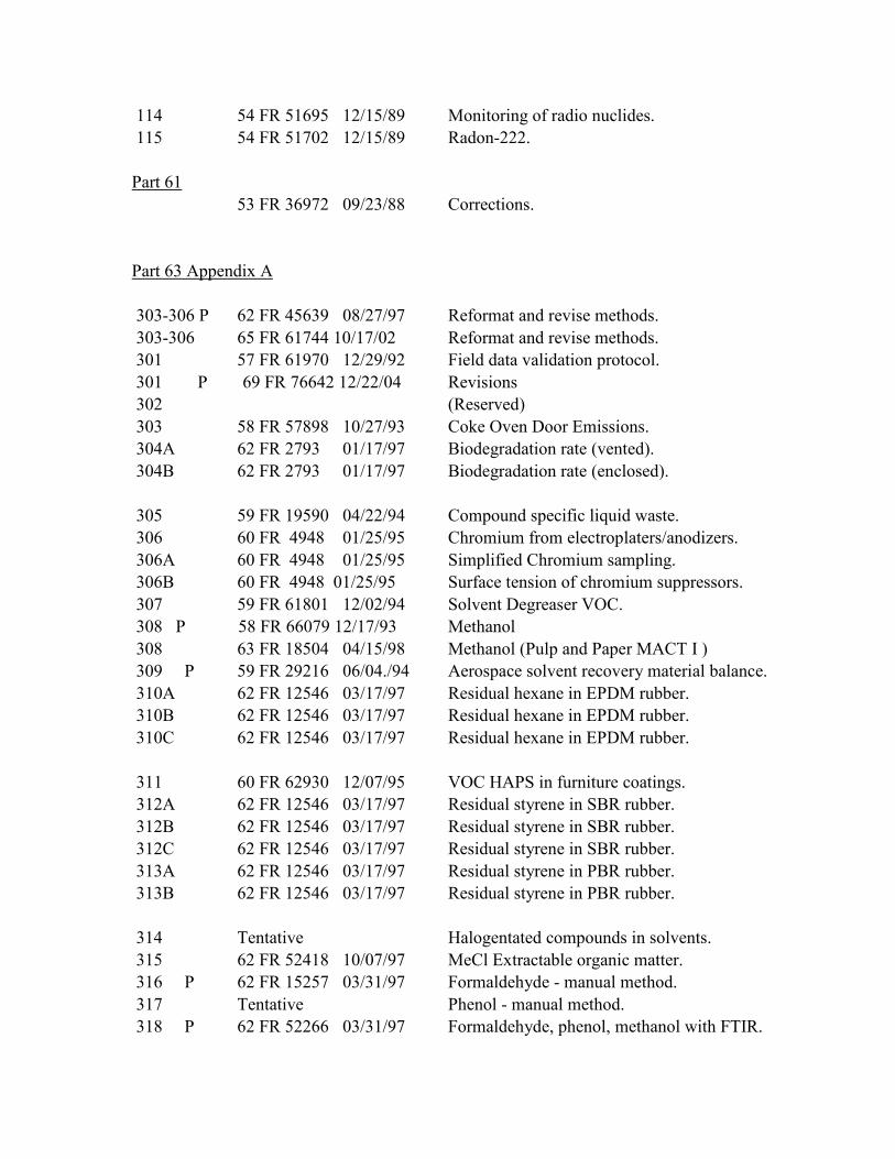
114 54 FR 51695 12/15/89 Monitoring of radio nuclides.
115 54 FR 51702 12/15/89 Radon-222.
Part 61
53 FR 36972 09/23/88 Corrections.
Part 63 Appendix A
303-306 P 62 FR 45639 08/27/97 Reformat and revise methods.
303-306 65 FR 61744 10/17/02 Reformat and revise methods.
301 57 FR 61970 12/29/92 Field data validation protocol.
301 P 69 FR 76642 12/22/04 Revisions
302 (Reserved)
303 58 FR 57898 10/27/93 Coke Oven Door Emissions.
304A 62 FR 2793 01/17/97 Biodegradation rate (vented).
304B 62 FR 2793 01/17/97 Biodegradation rate (enclosed).
305 59 FR 19590 04/22/94 Compound specific liquid waste.
306 60 FR 4948 01/25/95 Chromium from electroplaters/anodizers.
306A 60 FR 4948 01/25/95 Simplified Chromium sampling.
306B 60 FR 4948 01/25/95 Surface tension of chromium suppressors.
307 59 FR 61801 12/02/94 Solvent Degreaser VOC.
308 P 58 FR 66079 12/17/93 Methanol
308 63 FR 18504 04/15/98 Methanol (Pulp and Paper MACT I )
309 P 59 FR 29216 06/04./94 Aerospace solvent recovery material balance.
310A 62 FR 12546 03/17/97 Residual hexane in EPDM rubber.
310B 62 FR 12546 03/17/97 Residual hexane in EPDM rubber.
310C 62 FR 12546 03/17/97 Residual hexane in EPDM rubber.
311 60 FR 62930 12/07/95 VOC HAPS in furniture coatings.
312A 62 FR 12546 03/17/97 Residual styrene in SBR rubber.
312B 62 FR 12546 03/17/97 Residual styrene in SBR rubber.
312C 62 FR 12546 03/17/97 Residual styrene in SBR rubber.
313A 62 FR 12546 03/17/97 Residual styrene in PBR rubber.
313B 62 FR 12546 03/17/97 Residual styrene in PBR rubber.
314 Tentative Halogentated compounds in solvents.
315 62 FR 52418 10/07/97 MeCl Extractable organic matter.
316 P 62 FR 15257 03/31/97 Formaldehyde - manual method.
317 Tentative Phenol - manual method.
318 P 62 FR 52266 03/31/97 Formaldehyde, phenol, methanol with FTIR.
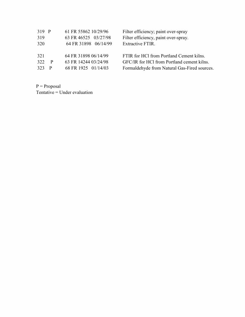
319 P 61 FR 55862 10/29/96 Filter efficiency; paint over-spray
319 63 FR 46525 03/27/98 Filter efficiency, paint over-spray.
320 64 FR 31898 06/14/99 Extractive FTIR.
321 64 FR 31898 06/14/99 FTIR for HCl from Portland Cement kilns.
322 P 63 FR 14244 03/24/98 GFC/IR for HCl from Portland cement kilns.
323 P 68 FR 1925 01/14/03 Formaldehyde from Natural Gas-Fired sources.
P = Proposal
Tentative = Under evaluation