all-season patio room assembly and installation … patio room aspr-05.pdfwhen the floor channel...
TRANSCRIPT

All-Season Patio RoomAssembly and Installation
Instructions(Use in conjunction with All-Season Sunroom Sliding Glass Door Installation Instructions)
Dura-Bilt Products, Inc. P.O. Box 188 Wellsburg, N.Y. 14894Dealer Service 570-596-2000 E-Mail [email protected]
DURA-BILT RESERVES THE RIGHT TO CHANGE DESIGN AND/OR SPECIFICATIONS WITHOUT NOTICE.
Check the material received.Match your shipment with the Bill of Materials.
If there is a shortage or wrong material,call Dealer Service immediately.
Safety is important!Wear Safety Glasses and Work Gloves.
Follow all safety practices while assemblingand installing this product.
Read the instructions before starting the job. They explain the steps requiredto produce a fi nished product that will meet factory specifi cations.All references to “Left” and “Right” are while facing the home.
ASPR-13

Tools RequiredCordless Drill Tape Measure Metal Saw Level Chalk Line Clamp Hammer Utility Knife Caulk Gun Silicone Lubricant Spray Masking Tape
Nut Driver Bits with Magnetic Head: 1/4” - 5/16” Drill Bits: 3/16” - 13/64” - 1/4” Masonry
Page 1
Foam UniversalSpacer InsulatorInner Foam Corner Insulator
Component Descriptions
Foam Panel Frame Insulator
Foam Door Header Insulator Deluxe Header Extension Universal Spacer
Outer Foam Corner Insulator
Fasteners
Fastener Description
#8 X 1/2” Self Drilling Screw
#12 X 3/4” Self Drilling Screw
#12 X 2” Slotted Hex Head Screw
#10 X 1” Hex Head ScrewMagni 599 Coated
Plastic Lag Shield
Nylon Spacer Washer
1/2” x 3/4” Foam Tape (For underside of Front Beam and Gable End Channel)

Component Descriptions
Page 2
Gable End Channel Gable End Channel Clamp Floor Channel
Corner Joiner Wall Channel
True “H” Bar Front Beam Cover Header Extension Joiner
Gable & Wall Trim Angle1-1/2” X 1-1/4” X 1/16”
Panel FrameFront BeamDeluxe Front Header Cover(Used for Roof Extension)
Page 3
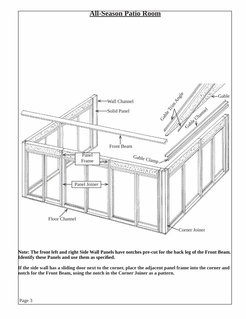
All-Season Patio Room
Front Beam
Corner Joiner
Wall Channel
Solid Panel
Floor Channel
Gable Clamp
Gable C
hannel
Gable
Trim
Ang
lePanel Joiner
PanelFrame
Gable
Note: The front left and right Side Wall Panels have notches pre-cut for the back leg of the Front Beam. Identify these Panels and use them as specifi ed.
If the side wall has a sliding door next to the corner, place the adjacent panel frame into the corner and notch for the Front Beam, using the notch in the Corner Joiner as a pattern.

Installation Basics
The installation is completed in three stages.
1. Stage One: Layout and install Floor Channel, Mounting Rail and Wall Channel.
2. Stage Two: Install the Wall and Door Frames.
3. Stage Three: Install Roof and Gable Ends.
3. Stage Four: Install Glass and Screen Panels.
It is suggested that you read these instructions completely before starting the job. They detail the steps in each of the three stages of the project.
All references to ‘Left and ‘Right are while you are facing the room from outside the room.
As in all quality construction, key elements are to be kept square, level and plumb. This is especially critical with the Floor Channel and Wall Channel. Taking the time to install these correctly will help avoid problems later in the project.
Because of the wide variety of patio, porch and deck fl oors, it is left to the judgment of the job contractor on how best to level the Floor Channel.
The length of Front Wall is distance between the outside edge of the Side Floor Channels. Length of the Side Walls is from the back of the Wall Channel to the front of the Floor Channel. The measurements in your Project Planner are these outside measurements.
*If you are installing a Dura-Bilt Roof and All-Season Room at the same time, the Mounting Rail is to be installed in Stage One. Establishing the Mounting Rail location is covered in these instructions. However, you must follow the Dura-Therm or Dura-Lock instructions for proper Mounting Rail installation procedures.
If the roof is already installed, it is necessary to raise the front of the roof several inches above the fi nal height of the room wall. Brace the roof solidly in position. Remove any Roof Post Assemblies not needed. If the existing Front Header will interfere with the All Season Front Beam, it must be removed. New screws are provided for the new All Season Front Beam.
Because you may encounter out of plumb home walls or some growth in the side walls of the room, the two Starter Panels will give you the fl exibility to position them within the wall channel or to cut down their width, if necessary.
Page 4

Stage OneMarking Floor Channel Locations
1. Find the previously determined location of the back Right Corner of the room. Mark that location on the home at the deck level.
Get the length of the Right Side Wall from the Project Planner in your Installation Package. Mark this dimension on the deck with a chalk line.
Helpful Hint: Use the 3’ x 4’ x 5’ triangle method to make sure your wall is at a right angle to the home. See Drawing.
2. Determine the location of the back Left Corner of the room. (Use the Front Wall Length given in your Project Planner as a guide.) Mark the Left Side Wall with a chalk line the same way you marked the Right Side Wall.
It is important to use the 3’ x 4’ x 5’ triangle method again to be sure your Left Side Wall is at a right angle to the home.
3. Measure distance between front corners. It must be the same dimension as in your Project Planner. Then snap a chalk line to mark the Front Wall.
Marking Wall Channel Locations
1. At the Back Right Corner location of the room, use a carpenter’s level and a long straight edge to continue the line on the deck up the Right side of the home.
2. Refer to your Project Planner for the Mounting Rail height provided when this order was placed. Otherwise refer to the Mounting Rail Height Chart in the Roof Installation Instruction Book. Then mark the point where bottom edge of the Mounting Rail will be located. See Drawing at top of Page 6.
3. Move to the Back Left Corner of the room and repeat process used in Step 1 of Marking Wall Channel Locations.
Page 5

Mounting Rail Heigtht
Use This chart to determine Mounting Rail Height
Note: Actual Front Wall Height at the Front Beam will be 3/4” higher when measured from Deck or Patio to underside of Roof as listed in the Wall Height Chart. (Example: 82-3/16” + 3/4” = 82-15/16”)
The minimum and maximum Mounting Rail heightsgiven in the chart above are calculated to bracketthe six degree pitch built into the Mounting Railand Front Beam. In theory, there should be nogaps between the roof and the Front Beam and/orthe Mounting Rail. However, there may be installations where gaps may still occur due tolocal installation conditions.
Page 6
RoomWidth
Front Wall Height82-3/16” 90” 96” 102”
Height to Bottom of Mounting RailMin. Max. Min. Max. Min. Max. Min. Max.
8’ 91” 93-1/8” 98-3/4” 100-7/8” 104-3/4” 106-7/8” 110-3/4” 112-7/8”9’ 92” 94-3/8” 99-3/4” 102-1/8” 105-3/4” 108-1/8” 111-3/4” 114-1/8”10’ 93” 95-5/8” 100-3/4” 103-3/8” 106-3/4” 109-3/8” 112-3/4” 115-3/8”11’ 94” 96-7/8” 101-3/4” 104-5/8” 107-3/4” 110-5/8” 113-3/4” 116-5/8”12’ 95” 98-1/8” 102-3/4” 106” 108-3/4” 112” 114-3/4” 118”13’ 96” 99-3/8” 103-3/4” 107-1/4” 109-3/4” 113-1/4” 115-3/4” 119-1/4”14’ 97” 100-5/8” 104-3/4” 108-1/2” 110-3/4” 114-1/2” 116-3/4” 120-1/2”15’ 98” 101-7/8” 105-3/4” 109-3/4” 111-3/4” 115-3/4” 117-3/4” 121-3/4”16’ 99” 103-1/8” 106-3/4” 111” 112-3/4” 117” 118-3/4” 123”

Marking Mounting Rail Location
1. From the Project Planner get the distance the Roof is to extend beyond the Right Side Wall. This is found in “Roof” information box on front cover. Mark the distance from the top of your Wall Channel line to the Right. Be sure it is level.
2. Move Back to Left Side Wall Channel location and mark the Left Side roof extension to the left of the Wall Channel. Be sure its level.
3. Using a chalk line, snap a line on the home joining the two lines you have just made. This marks where the bottom edge of the Mounting Rail is to be located.
Attaching Mounting Rail for Roof
Follow the instructions provided with the Dura-Bilt Roof you are installing.
Install Floor Channel
Place Right Side Floor Channel sections on deck with outside of the Floor Channel aligned with Line “A” established in Step 1, Page 5. High side of the Floor Channel is to be inside room.
Continue laying out the Front and Left Side Floor Channel sections. Then make sure that the Floor Channel dimensions agree with measurements given in the Project Planner.
Floor Channel Continued on Next pagePage 7
Deck or Patio
MountingRailHeight
Home
Deck or PatioLine
“A”
Home
Page 8
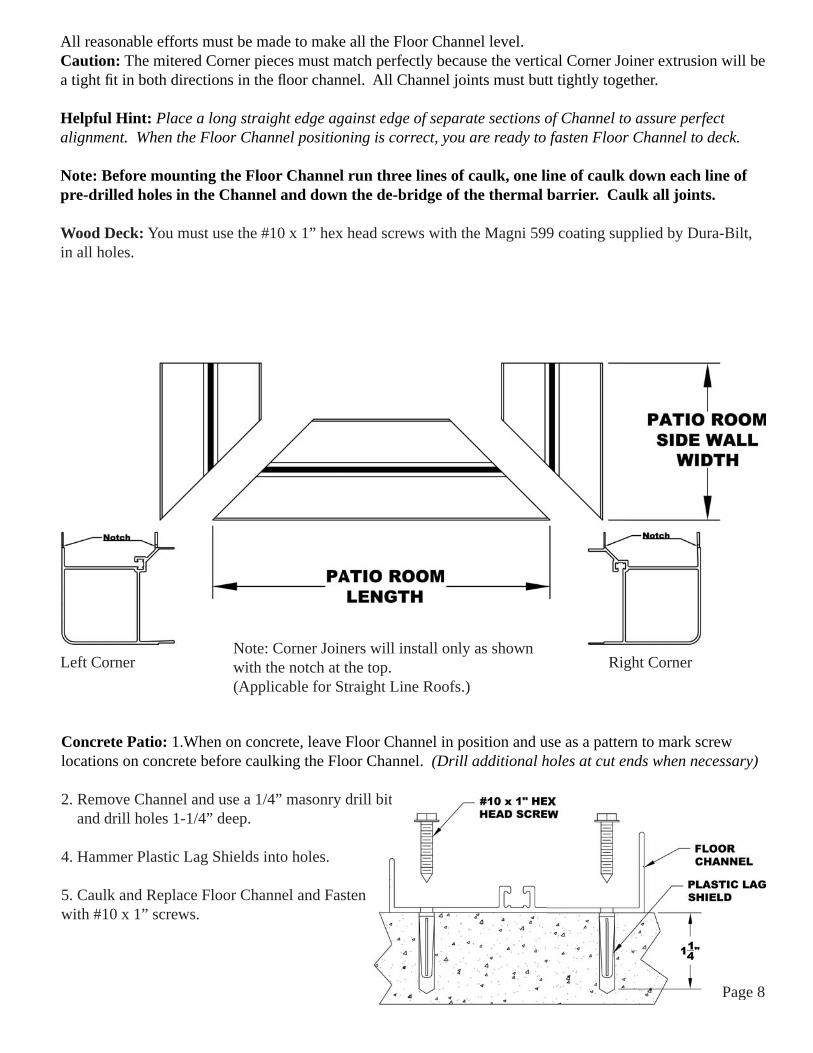
All reasonable efforts must be made to make all the Floor Channel level.Caution: The mitered Corner pieces must match perfectly because the vertical Corner Joiner extrusion will be a tight fi t in both directions in the fl oor channel. All Channel joints must butt tightly together.
Helpful Hint: Place a long straight edge against edge of separate sections of Channel to assure perfect alignment. When the Floor Channel positioning is correct, you are ready to fasten Floor Channel to deck.
Note: Before mounting the Floor Channel run three lines of caulk, one line of caulk down each line of pre-drilled holes in the Channel and down the de-bridge of the thermal barrier. Caulk all joints.
Wood Deck: You must use the #10 x 1” hex head screws with the Magni 599 coating supplied by Dura-Bilt, in all holes.
Concrete Patio: 1.When on concrete, leave Floor Channel in position and use as a pattern to mark screw locations on concrete before caulking the Floor Channel. (Drill additional holes at cut ends when necessary)
2. Remove Channel and use a 1/4” masonry drill bit and drill holes 1-1/4” deep.
4. Hammer Plastic Lag Shields into holes.
5. Caulk and Replace Floor Channel and Fastenwith #10 x 1” screws.
Left Corner Right CornerNote: Corner Joiners will install only as shown with the notch at the top.(Applicable for Straight Line Roofs.)
N t C J i ill i t ll l h
Page 8
bit
Page 9
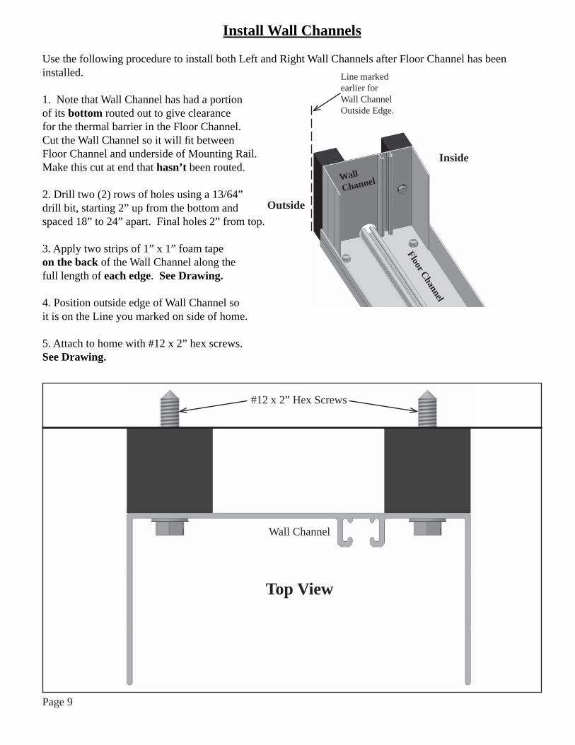
Install Wall Channels
Use the following procedure to install both Left and Right Wall Channels after Floor Channel has been installed.
1. Note that Wall Channel has had a portion of its bottom routed out to give clearance for the thermal barrier in the Floor Channel. Cut the Wall Channel so it will fi t between Floor Channel and underside of Mounting Rail. Make this cut at end that hasn’t been routed.
2. Drill two (2) rows of holes using a 13/64”drill bit, starting 2” up from the bottom andspaced 18” to 24” apart. Final holes 2” from top.
3. Apply two strips of 1” x 1” foam tapeon the back of the Wall Channel along the full length of each edge. See Drawing. 4. Position outside edge of Wall Channel so it is on the Line you marked on side of home.
5. Attach to home with #12 x 2” hex screws. See Drawing.
Outside
Inside
Line markedearlier forWall ChannelOutside Edge.
#12 x 2” Hex Screws
Wall Channel
Top View
WallChannel
Floor Channel

Page 10
Stage TwoBasics of The Wall and Door Panel Assembly
(Use in conjunction with All-Season Sunroom Sliding Glass Door Installation Instructions)
Wall, Door and Solid Panels have factory installed Panel Frames (H-Bars) on each unit. You will be slipping the legs of the Panel Frames together and fastening them with screws to build the walls of the room. (Sliding Glass Door Frames and Panel Frames are assembled at the job site).
Occasionally these instructions will make references to your Right or Left. It is important that you remember these are based on your being outside the room. Please observe that the Panel Frames have one side or “leg” that has an inset while the other leg is fl at. The Panel Frame leg with the inset will always be on your Right. The inset will slide behind the fl at Panel Frame Leg of the adjacent panel. Note that the Panel Frames have semi-circle holes routed out of the Bottom of each Panel Frame. (See Illustration 1 on next page.) These provide clearance for the Thermal Barrier and the screws in the Floor Channel.
Helpful Hint: Your layout sheet provides the accumulated measurements of each wall. Before beginning installation of Wall Panels, take a few moments to mark location of the panel joints on the fl oor next to the Floor Channel. This is an easy guide to make sure the wall is not “growing” or “shrinking” as you proceed with the installation.
The Solid Panels in each wall are there to provide the fl exibility to correct any wall growing or shrinking beyond acceptable limits.
Installation of Wall Panels
These instructions are written on the basis of starting the installation with the Right Wall. You may start with the Left Wall of the room. However, this could cause confusion because the Left and Right references in these instructions are based on starting with the Right Wall.
For most installations you would (1) start at the home and work to the front corner, (2) work across the front wall to the other corner.
Another option is: (1) Move to the home and install the other side wall to the corner. (2) Slide the Corner Joiner into position by inserting into wall Panel Frame about one-half or two-thirds of the way up the wall and then sliding it down-and-in to its fi nal position.

Installing Starter Panel
1. You can begin installing Wall Panelsat either Right or Left Wall Channel. This instruction starts at the Right Wall Channel with the Right Starter Panel. This panel has a Panel Frame on one edge, start the other edge (without the Panel Frame) into the Wall Channel. The Bottom of Panel Frame has holes cut to fi t thermal barrier and screw heads in Floor Channel. (See Illustration 1) Seat the Panel in the Floor Channel. Do not fasten Starter Panel in Wall Channel at this time. Insert Panel Frame Insulator into the Panel Frame on the Starter Panel.
Helpful Hint: Use your fi ngers to break out a piece of foam, (3/8” x 5/8”) to give thermal barrier clearance in Floor Channel. Tape Panel Frame Insulator in position while installing next panel.
2. Following your Project Planner, use your All-Season SunroomSliding Glass Door Installation Instructions to install the Sliding Door(s)to the solid panel or Corner Joiner. Insert Panel Frame of the next Panelinto the Panel Frame of the fi rst Sliding Door just installed. InstallPanel Frame Insulator in panel just installed. Then install next door.Fasten Panel Joiner at top, center and bottom of both inside and outsideof Panel Joiner using #8 x 1/2” self-drilling screws. Do not install screwsin Floor Channel at Panel Frame until Corner Joiner has been installed.
Note: Install foam tape to Panel Frames as indicated in the All-SeasonSunroom Sliding Glass Door Installation Instructions.
WallChannel
Illustration 1
Page 11
2”
2”
Center ofPanelSt
arte
r Pa
nel
Floor Channel
Wall Channel
Installing the Corner Joiner
Select the Corner Joiner that has the Inset Leg on the Right Side to joinwith Side Wall. (If Insert Leg is on Front Wall side, use other Joiner).Then slide the inset side behind the Panel Frame on the side wall as you havebeen doing with the Wall and/or Door Modules.
Note: that the Corner Joiner and adjacent Side Wall Panel have beennotched at the top for the back leg of the Front Beam. Be sure thatthe Corner Insulators are packed into each corner cavity.
The Corner Joiner needs to be plumb inboth directions—for the Side Wall and the Front Wall.
Install #8 x 1/2” Self-Drilling Screws as with the Side Wall installation.
The bottom of the Corner Joiner is notched to fi t over the thermal barrier. Top Viewof
Right Front Corner

Install the balance of Front Wall/Door Panels
1. Simply continue using the same procedure...making sure the “inset” side of Panel Frame is on your right while your on the outside of the room as you slide it behind the Panel Frame leg of the panel just installed. Fasten in position with #8 x 1/2” Self-Drilling Screws. Remember - put foam insulator in Panel Frame of Panel just installed.
2. Stop before you install the Left Front Corner Joiner. Make sure the Inset is on the right, joining the last Front Panel. Also check that the Joiner is plumb in both directions as you did with the Right Front Corner Joiner.
3. Continue installing the Sliding Door(s)/Solid Panels shown in your Project Planner until you have completed the Room Walls installation at a Corner Joiner.
4. Install #8 x 1/2” Screws through Floor Channel into each Panel Frame, inside and outside.
Front Beam Installation
1. Remove paper from the back of the 1/2” x 3/4” Foam Tape and stick two (2) rows to the underside of the Front Beam. (See Drawing)
2. The Front Beam fi ts down over the top of the Wall/Door Panels. Refer to your Layout Sheet for Front Beam placement. If you have two or more sections of Beam, the Layout Sheet shows proper sequence. Note that the Corner Joiner and Front Side Panel have notches pre-cut for back leg of Beam.
3. Working inside the room, fasten Beam in place with #12 x 3/4” Self-Drilling Screws at corners and at each Panel Frame where they join. It is suggested the screws be installed in the wider leg of the Panel Frame. Screws are installed outside the room and are placed in the same location as inside the room after the roof is installed.If you are adding a Front Header Extension, please refer to Page 14. Gable End Channel Installation1. Measure from inside leg (back) of Wall Channel to the back ofthe Front Beam. Cut the Gable End Channel and Gable EndChannel Clamp to length. Then cut notches in Gable EndChannel to allow the Wall Channel legs to slide into theGable End Channel. Also cut relief for the Wall Channel thermalbarrier. Then Remove paper from back of the 1/2” x 3/4”Foam Tape and stick two (2) rows to the underside of theGable End Channel.(High leg of the Gable End Channel goes inside the room.)
Page 12
Front BeamFront RightSide Panel
Right Corner Joiner
1/2” x 3/4” Foam Tape
2”
1/8” 3/4”
Gable End Channel
15/16”
3/8”

2. Install the Gable End Channel by sliding it back into the Wall Channel and then down over the top of the side wall of the room.
3. From inside the room, place a straight edge fl at on the top of the Front Beam and continuing along the side of the Gable End Channel Leg. Draw a line marking this angle. Trim the excess. Fasten with #8 x 1/2”Self-Drilling Screws placed in same positions as whenfastening Front Beam.
4. Match this same angle cut on the Gable Clamp.
5. Repeat these procedures for the other Gable.
Stage ThreeInstall Roof per Instructions provided with Roof.
If a Roof Header Extension is required install it First. See Page 14.Install screws on outside of Front Beam.
After Roof is Installed, continue here for Gables
Cutting Gable to Fit
The 24” wide panel(s) provided is to be cut to match your roof pitch.
1. Start layout for cutting the Panel bygetting measurement “A” which is along the top of the Side Wall, from thermalbarrier inside Wall Channel to back of Front Beam.
2. Measurement “C” is 3/8” up the side of Panel from edge of “A”.
3. “D” is line drawn between “B” and “C”.Mark Line “D” on both sides of 4” thick panelbecause you will need to cut from both sides withstandard skill saw. Cut panel on line “D”. Repeatsteps 2 and 3 for other gable.
4. Install Gable into position from outside the room.
5. Install the Gable Clamp using #8 x 1/2” screws.
6. Cut Gable Trim Angles to length; from the home to the back of the Front Beam. If you have installed a Header Extension, the Gable Trim Angle should extend to back of Front Header and cover the open portion of the Front Beam. Apply a bead of caulk and install theGable Trim Angles with #8 x 1/2” screws approximately every 12”.
Front Beam Gable End
Channel
Trim Excess
Gable TrimAngle
Caulk
Roof Panel
Gable #8 x 1/2”Screws
Page 13

Page 14
Front Beam Cover
Insert the Front Beam Cover intothe bottom of the Front Beam.Fasten with #8 x 1/2” Screws.
Header “Slice”
Installing Roof Header Extension Joiner
1. Locate the Header Extension Joiner that is pre-inserted into a “Slice” of Header.
2. Position the Header “Slice” to match the front of the Front Beam at the Corner of the room where the roof will be continued. See Drawing.
3. Use two #12 x 1” Self-Drilling Screws and two Nylon Spacer Washers in the pre-drilled holes to attach Joiner to the Corner Joiner.Note: If Header “slice” is facing backwards, slide it off the Joiner, reverse it and then re-position on the Joiner.

4. Remove Header “Slice” (it is no longer needed) and install the Header. Secure the Header to the Joiner with four (4) #12 x 3/4” Self Drilling Screws . . .two (2) in the front side and two (2) in the back side of the Header.
5. Locate and install Post Anchor Bracket on deck or patio. Then locate and install Post(s) using #12 x 3/4” screws to attach to the Roof Header Extension. (See your Roof Installation instructions for Anchor Brack-et installation)
6. Measure and cut to length the Deluxe Front Header Cover to fi t on both sides of the Post(s). Install by using #8 x 1/2” Screws as shown below.
Note: If you are installing Columns on a Pressure Treated Lumber Deck. With your order you will receive a 4” x 4-1/2” piece of Black Flashing with paper coated adhesive on one side for each Dura-Post and Deluxe Post.Peel the paper off from the Flashing and stick the fl ashing to the bottomof the Anchor Bracket. Then trim the excess Flashing from around theAnchor Bracket.
Page 15