all in one multi-purpose cable tester and cable tracer€¦ · · 2016-04-14all in one...
TRANSCRIPT
INSTRUCTION MANUAL
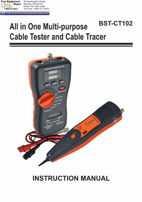
All in One Multi-purposeCable Tester and Cable Tracer
BST-CT102
99 Washington Street Melrose, MA 02176 Phone 781-665-1400Toll Free 1-800-517-8431
Visit us at www.TestEquipmentDepot.com
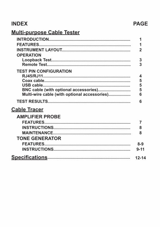
INDEX PAGEMulti-purpose Cable Tester
INTRODUCTION...................................................................... 1FEATURES............................................................................... 1INSTRUMENT LAYOUT........................................................... 2OPERATION
Loopback Test....................................................................Remote Test........................................................................
33
TEST PIN CONFIGURATIONRJ45/RJ11...........................................................................Coax cable..........................................................................USB cable...........................................................................BNC cable (with optional accessories)............................Multi-wire cable (with optional accessories)...................
45556
TEST RESULTS....................................................................... 6
Cable TracerAMPLIFIER PROBE
FEATURES.......................................................................... 7INSTRUCTIONS.................................................................. 8MAINTENANCE................................................................... 8
TONE GENERATORFEATURES.......................................................................... 8-9INSTRUCTIONS.................................................................. 9-11
Specifications....................................................................... 12-14

-1-
Multi-purpose Cable TesterINTRODUCTION
● A newly designed tool that can easily test the correct pin configuration of the RJ45/RJ11 modular cables, USB, COAX, BNC cable & Multi-wire
cable. ● By comparing one transmitting end and the corresponding receiving end, the Multi-purpose Cable Tester also can test installed cable far away by using the receiving unit. ● The tester provides the variety for wiring check, such as cable continuity, open status, short status and miss-wired.
FEATURES ● Designed for testing : -RJ45/RJ11 -USB-COAX -BNC cable-Multi-wire cable ● The tester can verify cable continuity, open, short circuit and miss-wired. ● The receiving unit is available for installed cables far away either on the
wall plates or on the patch panels. ● Auto-scan and manual-check function. ● Buzzer sound warning for wire status. ● 2 LED module indicators on the master unit which can do both of transmitter and receiver functions for RJ45/RJ11 cable testing. Users
don’t need to use the receiving unit. ● Ground ( shielded ) wire test. ● Display: indication by LED modules for wire status. ● Power source : 9V battery ● Safety standard:EN 61326-1EN 55011EN 61000-4-2EN 61000-4-3
-2-
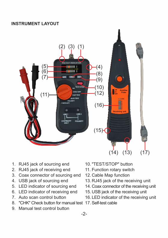
INSTRUMENT LAYOUT
1. RJ45 jack of sourcing end2. RJ45 jack of receiving end3. Coax connector of sourcing end4. USB jack of sourcing end5. LED indicator of sourcing end6. LED indicator of receiving end7. Auto scan control button8. "CHK" Check button for manual test9. Manual test control button
10. "TEST/STOP" button11. Function rotary switch12. Cable Map function13. RJ45 jack of the receiving unit14. Coax connector of the receiving unit15. USB jack of the receiving unit16. LED indicator of the receiving unit17. Self-test cable
(8)
(2) (1)(3)
(5)(6)(7)
(10)(11) (12)
(13)(14)
(16)
(17)
(4)
(9)
(15)
-3-
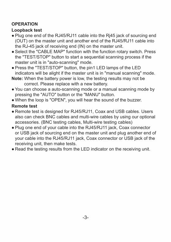
OPERATIONLoopback test
● Plug one end of the RJ45/RJ11 cable into the Rj45 jack of sourcing end (OUT) on the master unit and another end of the RJ45/RJ11 cable into
the RJ-45 jack of receiving end (IN) on the master unit. ● Select the "CABLE MAP" function with the function rotary switch. Press the "TEST/STOP" button to start a sequential scanning process if the master unit is in "auto-scanning" mode. ● Press the "TEST/STOP" button, the pin1 LED lamps of the LED
indicators will be alight if the master unit is in "manual scanning" mode.Note: When the battery power is low, the testing results may not be
correct. Please replace with a new battery. ● You can choose a auto-scanning mode or a manual scanning mode by
pressing the "AUTO" button or the "MANU" button. ● When the loop is "OPEN", you will hear the sound of the buzzer.
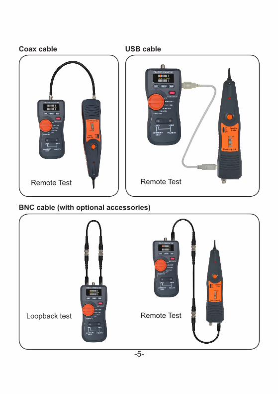
Remote test ● Remote test is designed for RJ45/RJ11, Coax and USB cables. Users also can check BNC cables and multi-wire cables by using our optional
accessories. (BNC testing cables, Multi-wire testing cables) ● Plug one end of your cable into the RJ45/RJ11 jack, Coax connector or USB jack of sourcing end on the master unit and plug another end of your cable into the RJ45/RJ11 jack, Coax connector or USB jack of the receiving unit, then make tests. ● Read the testing results from the LED indicator on the receiving unit.

-4-
Wall Plate Patch Panel
TEST PIN CONFIGURATIONRJ45/RJ11
Receivingend (IN)
Loopback Test
Sourcingend (OUT)
Remote Test
-5-
Coax cable
Remote Test
USB cable
Remote Test
BNC cable (with optional accessories)
Loopback test Remote Test
-6-
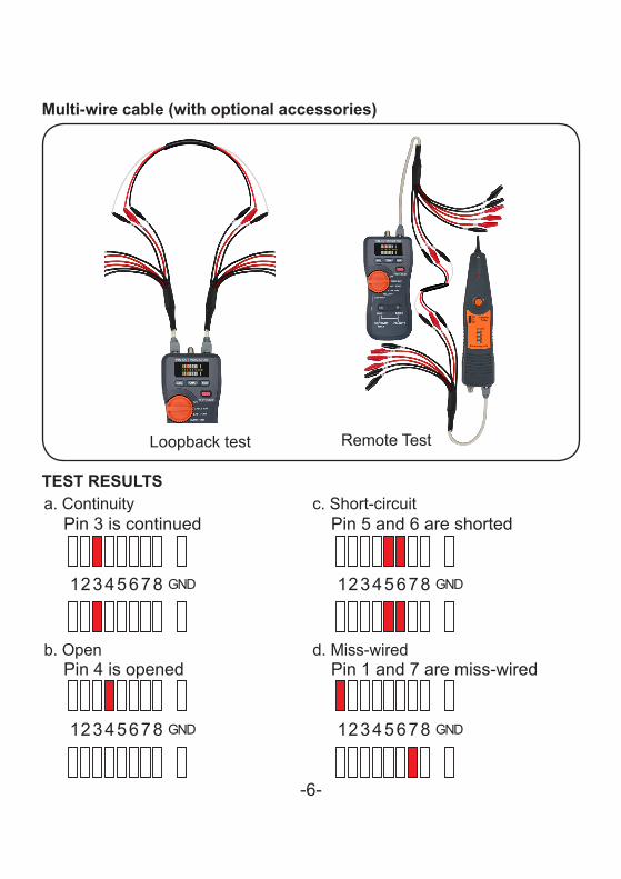
Multi-wire cable (with optional accessories)
Loopback test Remote Test
TEST RESULTSa. Continuity c. Short-circuit
b. Open d. Miss-wired

-7-
Cable Tracer
AMPLIFIER PROBEFEATURES
● The Amplifier Probe is designed to identify and trace wires or cables within a group without damaging the insulation.
● The flashlight function for easier cable tracing in the dark. ● An LED indication for the signal strength ● Works with any Tone Generator to identify wires. ● Volume control for increased sensitivity and adjustable to suit work
environment. ● Recessed ON/OFF button prevents battery drain. ● Power supply is from any 9V battery with a life of approximately 100
hours. ● An audio jack is provided for headset.
ON/OFFbutton
LED of signalstrength
Sensitivity control
Phone jack
Flashlight
Figure1.Cable tracing
Flashlightswitch
Function rotaryswitch
LINE1LED LINE2
LED
RJ11connectorAlligator clips

-8-
INSTRUCTIONS ● Connecting the tone generator.In terminated working cables:Connect one test lead to a terminated wire and the other test lead to earth or equipment ground.(See Figure 1)In unterminated or non-working cables:Connect one test lead to an unterminated wire and the other test lead to another unterminated wire.
MAINTENANCEThe amplifier probe is maintenance free except for battery replacement. Remove the screw from the battery compartment, replace the 9V battery and reassemble.Warranty limited solely to repair or replacement; no warranty of merchantability, fitness for a particular purpose or consequential damages.
TONE GENERATOR
Fast tone
Slow tone
Figure2
Function rotaryswitch

-9-
FEATURES ● Tone Generator is a great tool for locating and identifying cable pairs or
individual conductors. ● Two bi-colored LEDs for Line1 and Line 2 indication of the polarities of
the telephone lines. ● Identifying Tip and Ring of telephone lines. ● Identifying telephone line condition : Clear line, Busy line and Ringing line. ● It does not only serves as a tone generator, but it also serves as a
continuity and polarity tester. ● Users can select a fast dual tone or a slow dual tone by the function
rotary switch. (See Figure 2) ● The unit has red and black alligator type terminals, a modular cable of 4
conductors with a strong connector. ● The continuity function only applies to Line1.
INSTRUCTIONSAll of the following tests can be performed by using the red and black test leads or the modular plug.NOTE:When using the modular test plug, the polarity test function applies to Lines 1 and 2. The continuity function ONLY applies to Line 1.
Figure3
-10-
● POLARITY TEST: IDENTIFYING TIP & RING (SWITCH TO "POLARITY")1. Connect the RED test lead to the side of one line and the BLACK lead
to the side of another line. (See Figure 3)2. The LED will glow "GREEN" when you connect the RED test lead to
the RING SIDE of the line.3. The LED will glow "RED" when you connect the RED test lead to the
TIP SIDE of the line.
● IDENTIFYING LINE CONDITION (SWITCH TO "POLARITY")1. Connect the RED test lead to the RING SIDE of the line and the
BLACK to the TIP. (See Figure 3)2. Watch the LED:
1.1 A BRIGHT "GREEN" LED indicates a CLEAR line.1.2 A DIM "GREEN" LED indicates a BUSY line.1.3 A BRIGHTLY FLICKERING "GREEN and RED" LED indicates a
RINGING line.
● VERIFYING LINES (SWITCH TO "POLARITY" THEN "CONTINUITY") 1. Dial the line to be verified.2. While the line is ringing, connect the RED lead to the RING SIDE of
the line and the BLACK to the TIP.3. In the "POLARITY" position, the indicator lamp will flicker "RED and
GREEN" when the test leads are connected to the subject pair.4. If you switch the test set to "CONTINUITY", it will terminate the call on
the subject line.
● SENDING TONE (SWITCH TO "FAST TONE" or "SLOW TONE")
CAUTION:DO NOT CONNECT TO ANY ACTIVE AC CIRCUIT EXCEEDING 24V IN THIS MODE.
1. Connect the test leads to the pair, or attach one lead to ground andone lead to either side of the line.(See Figure 1)
2. A fast dual alternating tone, or a slow dual alternating tone can beselected from the function rotaty switch.

-11-
3. Probe the suspected wires with the amplifier probe. Reception of tonewill be strongest on the subject wire. In case of ready access to bareconductors, a handset or headphone may be used to receive the tone.
● TESTING CONTINUITY (SWITCH TO "CONTINUITY")
CAUTION:DO NOT CONNECT TO ANY ACTIVE AC OR DC CIRCUIT IN THIS MODE.
1. Connect the test leads to the subject pair.2. Switch to "CONTINUITY".3. A bright "GREEN" light indicates continuity. The LED will not glow if
the line resistance exceeds 12kΩ
● TESTING CONTINUITY BY USING TONE (SWITCH TO "FAST TONE" or "SLOW TONE")
CAUTION:DO NOT CONNECT TO ANY ACTIVE AC OR DC CIRCUIT IN THIS MODE.
1. Connect the test leads to the subject pair.2. Use a handset or headset at the remote end and touch the wire end(s)
with the clip lead(s).3. Reception of tone is an indication of continuity.
● MODULAR TESTING 1. All above tests are available through the modular plug for line 1 only - red and green wires.
● COAX TESTING1. To test unterminated coax, connect red to outer shield and black to
center conductor or red to outer shield and black to ground.2. To test terminated coax, connect red to connector housing and black
to center pin or red to connector housing and black to ground.

-12-
SpicificationsMaster unit & Tone Generator
Display LED ModulesBi-colored LEDs
Waveform Square waveFrequency 1kHz±15%Over Voltage Protection 80V DCSingle ToneAlternating Tone Fast and slowConnection RJ11 connector
Amplifier Probe & Receiving unitFrequency Detection 1Hz~12kHzReceiver Distance <50cmSensitivity Control VFlash light VLED for signal strength VLED module V

-13-
GeneralOperating Temperature & Humidity 0°C~40°C, 80% Max
Storage Temperature & Humidity -10°C~50°C, 80% Max
Power Source Amplifier Probe & Receiving unit : 9V batteryMaster unit & Tone Generator : 9V battery
Dimensions
Amplifier Probe & Receiving unit :263(L) x 55(W) x 37.3(H)mmMaster unit & Tone Generator :180(L) x 82(W) x 43.8(H)mm
Weight Amplifier Probe & Receiving unit : 210gMaster unit & Tone Generator : 280g
Safety Standard EN 61326-1 EN 55011EN 61000-4-2 EN 61000-4-3
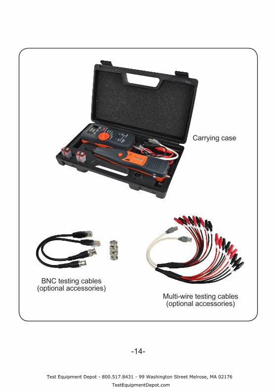
Accessories
Instruction manualBatteriesCarrying caseSelf-test cable
Optional Accessories BNC testing cablesMulti-wire testing cables
-14-
Carrying case
Multi-wire testing cables(optional accessories)
BNC testing cables(optional accessories)
Test Equipment Depot - 800.517.8431 - 99 Washington Street Melrose, MA 02176
TestEquipmentDepot.com