all crosby 320 eye hoist hooks incorporate the following … · · 2017-07-14zone a: repair not...
TRANSCRIPT

®
Copyright © 2016 The Crosby Group LLC All Rights Reserved114
HO
OK
S &
SW
IVEL
S
On Pages 142-143
SEE APPLICATION AND WARNING INFORMATION
S-320 / S-320N EYE HOOKS
All Crosby 320 Eye Hoist Hooks incorporate the following features: • The most complete line of Eye hoist hooks.• Available in carbon steel and alloy steel.• Designed with a 5:1 Design Factor for (Carbon Steel); 4.5:1 Design Factor for 30t - 60t (Alloy Steel).• Eye hooks are load rated.• Proper design, careful forging and precision controlled quenched and tempering give maximum strength without
excessive weight and bulk.• Every Crosby Eye Hook has a pre-drilled cam which can be equipped with a latch. Even years after purchase of
the original hook, latch assemblies can be added. (See pages 123 - 125)• Chemical analysis and tensile tests performed on each PIC to verify chemistry and mechanical properties.• Type Approval certification in accordance with ABS 2007 Steel Vessel Rules 1-11-17.7 and ABS Guide for
Certification on Cranes available. Certificates available when requested at time of order and may include additional charges.
• Hoist hooks incorporate two types of strategically placed markings forged into the product which address two (2)QUIC-CHECK® features:• Deformation Indicators and Angle Indicators (see following page for detailed definition).
The following additional features have been incorporated in the new Crosby S-320N Eye Hoist Hooks. (Sizes 3/4 metric ton Carbon through 22 metric ton Alloy.)• Metric Rated at 5:1 Design Factor for (Carbon Steel); 5:1 Design Factor for 1t - 22t (Alloy Steel).• Can be proof tested to 2 times the Working Load Limit.• Low profile hook tip.• New integrated latch (S-4320) meets the world-class standard for lifting.
• Heavy duty stamped latch interlocks with the hook tip.• High cycle, long life spring.• When secured with proper cotter pin through the hole in the tip of hook, meets the intent of OSHA Rule
1926.1431(g) and 1926.1501(g) for personnel hoisting.
L-320NEYE HOOK
Crosby® Eye Hooks
*Eye Hooks (3/4 TC - 22TA), Proof load is 2 times Working Load Limit. Eye Hooks (20 TC - 60TA). All carbon hooks-average straightening load (ultimate load) is 5 times Working Load Limit. Alloy eye hooks 1 ton through 22 ton-average straightening load (ultimate load) is 5 times Working Load Limit. Alloy eye hooks 30 tons through 60 tons-average straightening load (ultimate load) is 4.5 times Working Load Limit. † New 320N style hook.
S-320EYE HOOK
WorkingLoad Limit
(t)
Hook ID
Code
Eye HookStock No.
WeightEach(lbs.)
ReplacementLatch Kits
Carbon Alloy
CarbonS-320C
S-320CNS.C.
Carbon L-320C
L-320CNS.C.
CarbonG-320CN
Galv.
AlloyS-320A
S-320ANS.C.
AlloyL-320A
L-320ANS.C.
S-4320Stock No.
PLStock No.
SS-4055Stock No.
3/4 1 †D 1022200 1022205 1022208 1022375 1022380 .61 1096325 - -
1 1-1/2 †F 1022211 1022216 1022219 1022386 1022391 .89 1096374 - -
1-1/2 2 †G 1022222 1022227 1022230 1022397 1022402 1.44 1096421 - -
2 3 †H 1022233 1022238 1022241 1022406 1022413 2.07 1096468 - -
3 5 †I 1022244 1022246 1022249 1022419 1022424 4.30 1096515 1092000 -
5 7 †J 1022255 1022260 1022262 1022430 1022435 8.30 1096562 1092001 -
7-1/2 11 †K 1022264 1022271 1022274 1022441 1022446 15.00 1096609 1092002 -
10 15 †L 1022277 1022282 1022285 1022452 1022457 20.77 1096657 1092003 -
15 22 †N 1022288 1022293 1022296 1022465 1022468 39.50 1096704 1092004 -
20 30 O 1023289 1022302 - 1023546 1022477 60.00 - 1093716 1090161
25 37 P 1023305 - - 1023564 - 105.00 - 1093717 1090189
30 45 S 1023323 - - 1023582 - 148.00 - 1093718 1090189
40 60 T 1023341 - - 1023608 - 228.00 - 1093719 1090205

®
Copyright © 2016 The Crosby Group LLC All Rights Reserved 115
HO
OK
S &
SW
IVE
LS
On Pages 144 - 145
SEE APPLICATION AND WARNING INFORMATION
S-320 / S-320N EYE HOOKS
• Hoist hooks incorporate markings forged into the product which address two (2) QUIC-CHECK® features.• Deformation Indicators -- Two strategically placed marks, one just below the shank or eye and the other on the
hook tip, which allows for a QUIC-CHECK® measurement to determine if the throat opening has changed, thusindicating abuse or overload. To check, use a measuring device (i.e. tape measure) to measure the distancebetween the marks. The marks should align to either an inch or half-inch increment on the measuring device.If the measurement does not meet this criteria, the hook should be inspected further for possible damage.
• Angle Indicators -- Indicates the maximum included angle which is allowed between two (2) sling legs in the hook.These indicators also provide the opportunity to approximate other included angles between two sling legs.
L-320NEYE HOOK
C
Q
N
K
G
M
D
FAA
J
T
O O2
T2
Crosby® Eye Hooks
*Eye Hooks (3/4 TC-22TA), Proof load is 2 times Working Load Limit. Eye Hooks (20 TC-60TA). All carbon hooks - average straightening load (ultimate load) is 5 times Working Load Limit. Alloy eye hooks 1t through 22t - average straightening load (ultimate load) is 5 times Working Load Limit. Alloy eye hooks 30t through 60t - average straightening load (ultimate load) is 4.5 times Working Load Limit.** Deformation Indicators.† 3/4tC - 22tA dimensions shown are for S-4320 Latch Kits. Dimensions for sizes 20t carbon and larger are for PL Latch Kits.†† Dimensions are for PL-N latch kits.
HookID
Code*
Dimensions(in.)
C D F G J K M N O † O2 †† Q T † T2 †† AA**
D 3.34 2.83 1.25 .73 .90 .63 .63 .36 .89 - .75 .87 - 1.50
F 3.81 3.11 1.38 .84 .93 .71 .71 .42 .91 - .91 .98 - 2.00
G 4.14 3.53 1.50 1.00 1.00 .88 .88 .55 1.00 - 1.13 1.03 - 2.00
H 4.69 3.97 1.63 1.13 1.13 .94 .94 .58 1.09 - 1.25 1.16 - 2.00
I 5.77 4.81 2.00 1.44 1.47 1.31 1.31 .72 1.36 1.00 1.56 1.53 1.50 2.50
J 7.37 6.27 2.50 1.81 1.75 1.66 1.66 .90 1.61 1.31 2.00 1.96 1.88 3.00
K 9.07 7.45 3.00 2.25 2.29 1.88 1.63 1.11 2.08 1.81 2.44 2.47 2.25 4.00
L 10.08 8.30 3.25 2.59 2.50 2.19 1.94 1.27 2.27 2.00 2.84 2.62 2.31 4.00
N 12.53 10.30 4.25 3.00 3.30 2.69 2.38 1.56 3.02 2.75 3.50 2.83 2.56 5.00
O 14.06 13.62 5.00 3.62 4.00 3.00 3.00 1.75 3.25 - 3.50 3.44 - 6.50
P 18.19 14.06 5.38 4.56 4.25 3.75 3.19 2.00 3.00 - 4.50 3.88 - 7.00
S 20.12 15.44 6.00 5.06 4.75 4.50 3.25 2.18 3.38 - 4.94 4.75 - 8.00
T 23.72 18.50 7.00 6.00 5.75 5.50 3.91 2.53 4.12 - 5.69 5.69 - 10.00

Copyright © 2016 The Crosby Group LLC All Rights Reserved142
S-319 Series
S-3316 Series
S-320 Series
S-322 Series
Positioning Only
S-3322B
WARNING• Loads may disengage from hook if proper procedures are not
followed.• A falling load may cause serious injury or death.• See OSHA Rule 1926.1431(g)(1)(i)(A) and 1926.1501(g)(4)(iv)(B)
for personnel hoisting by cranes and derricks, and OSHADirective CPL 2-1.36 - Interim Inspection Procedures DuringCommunication Tower Construction Activities. A Crosby 319, 320 or 322 hook with a PL latch attached and secured with abolt, nut and cotter pin (or toggle pin) may be used for liftingpersonnel. A Crosby 319N, 320N or 322N hook with an S-4320latch attached and secured with cotter pin or bolt, nut and pin; or a PL-N latch attached and secured with toggle pin may beused for lifting personnel. A hook with a Crosby SS-4055 latchattached shall NOT be used for personnel lifting.
• See OSHA Directive CPL 2-1.36 - Crosby does not recommendthe placement of lanyards directly into the positive lockingCrosby hook when hoisting personnel. Crosby requires thatall suspension systems (vertical lifelines / lanyard) shall begathered at the positive locked load hook by use of a masterlink, or a bolt-type shackle secured with cotter pin.
• Threads may corrode and/or strip and drop the load.• Remove securement nut to inspect or to replace S-322, S-3316,
and S-3319 bearing washers (2).• Hook must always support the load. The load must never be
supported by the latch.• Never apply more force than the hook’s assigned Working Load
Limit (WLL) rating.• Read and understand these instructions before using hook.
from the hook body, or is in any other way distorted or bent. Note: A latch will not work properly on a hook with a bent or worn tip.
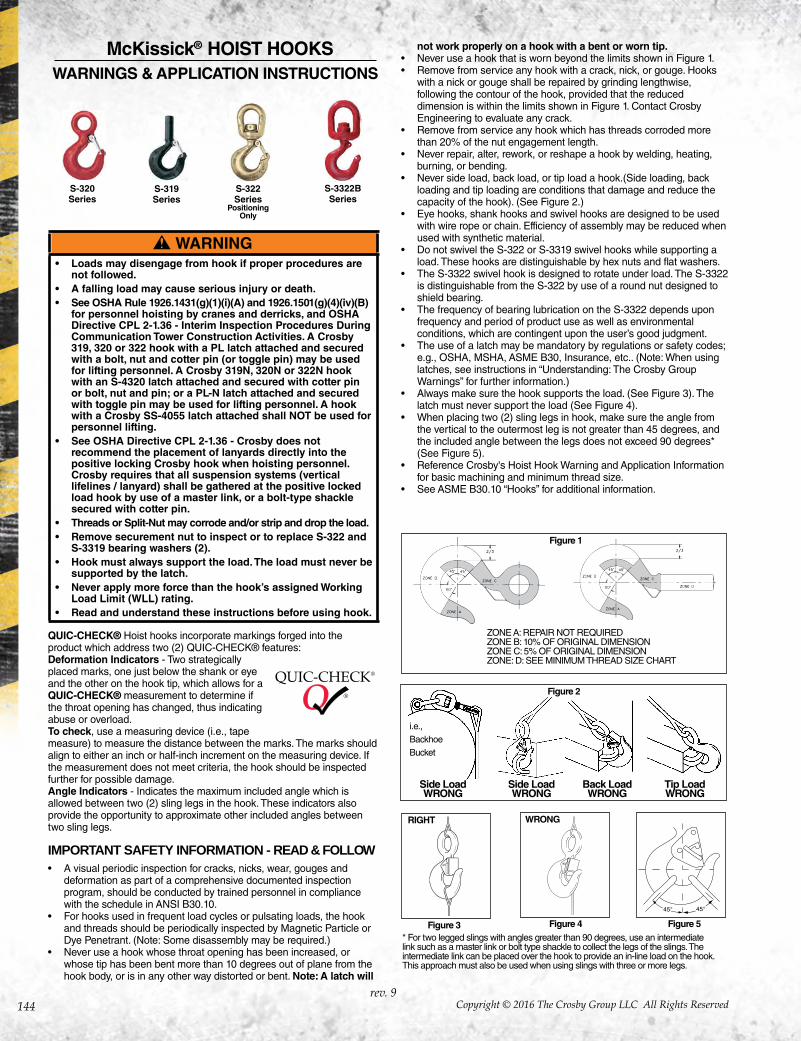
• Never use a hook that is worn beyond the limits shownin Figure 1.
• Remove from service any hook with a crack, nick, or gouge. Hooks with a nick or gouge shall be repaired by grindinglengthwise, following the contour of the hook, provided thatthe reduced dimension is within the limits shown in Figure 1. Contact Crosby Engineering to evaluate any crack.
• Never repair, alter, rework, or reshape a hook by welding,heating, burning, or bending.
• Never side load, back load, or tip load a hook.(Side loading,back loading and tip loading are conditions that damage andreduce the capacity of the hook). (See Figure 2.)
• Eye hooks, shank hooks and swivel hooks are designed to beused with wire rope or chain. Efficiency of assembly may bereduced when used with synthetic material.
• Do not swivel the S-322, S-3316, or S-3319 swivel hooks whilesupporting a load. These hooks are distinguishable by hexnuts and flat washers.
• The S-3322 swivel hook is designed to rotate under load. TheS-3322 is distinguishable from the S-322 by use of a round nutdesigned to shield bearing.
• The frequency of bearing lubrication on the S-3322 dependsupon frequency and period of product use as well asenvironmental conditions, which are contingent upon theuser’s good judgment.
• The use of a latch may be mandatory by regulations or safetycodes; e.g., OSHA, MSHA, ANSI/ASME B30, Insurance, etc.. (Note: When using latches, see instructions in “UnderstandingThe Crosby Group Warnings” for further information.)
• Always make sure the hook supports the load. (See Figure 3). The latch must never support the load (See Figure 4).
• When placing two (2) sling legs in hook, make sure the anglefrom the vertical to the outermost leg is not greater than 45degrees, and the included angle between the legs does notexceed 90 degrees* (See Figure 5).
• See ANSI/ASME B30.10 “Hooks” for additional information.
ZONE A: REPAIR NOT REQUIREDZONE B: 10% OF ORIGINAL DIMENSIONZONE C: 5% OF ORIGINAL DIMENSIONZONE: D: SEE MINIMUM THREAD SIZE CHART
* For two legged slings with angles greater than 90 degrees, use an intermediate link such as a master link or bolt type shackle to collect the legs of the slings. The intermediate link can be placed over the hook to provide an in-line load on the hook. This approach must also be used when using slings with three or more legs.
Figure 3 Figure 4 Figure 5
RIGHT RIGHTWRONG
Figure 2
Side LoadWRONG
i.e.,BackhoeBucket
Side LoadWRONG
Back LoadWRONG
Tip LoadWRONG
S-3319Series
PositioningOnly
Crosby® HOIST HOOKSWARNINGS & APPLICATION INSTRUCTIONS
QUIC-CHECK® Hoist hooks incorporate markings forged into the product which address two (2) QUIC-CHECK® features:1. Deformation Indicators – Two strategically placed marks,
one just below the shank or eye and the other on thehook tip, which allows for a QUIC-CHECK® measurementto determine if the throat opening haschanged, thus indicating abuse oroverload.To check, use a measuringdevice (i.e., tape measure) to measurethe distance between the marks. Themarks should align to either an inchor half-inch increment on the measuring device. If themeasurement does not meet criteria, the hook should beinspected further for possible damage.
2. Angle Indicators – Indicates the maximum includedangle which is allowed between two (2) sling legs in thehook. These indicators also provide the opportunity toapproximate other included angles between two slinglegs.
IMPORTANT SAFETY INFORMATION - READ & FOLLOW A visual periodic inspection for cracks, nicks, wear, gouges and deformation as part of a comprehensive documented inspection program, should be conducted by trained personnel in compliance with the schedule in ANSI B30.10.• For hooks used in frequent load cycles or pulsating loads, the
hook and threads should be periodically inspected by MagneticParticle or Dye Penetrant. (Note: Some disassembly maybe required.)
• Never use a hook whose throat opening has been increased,or whose tip has been bent more than 10 degrees out of plane
Figure 1

Copyright © 2016 The Crosby Group LLC All Rights Reserved 143
HO
OK
S &
SW
IVE
LS
Warning and Application Instructions For Crosby® Hook Latch Kit
WARNING• Loads may disengage from hook if proper procedures are
not followed.• A falling load may cause serious injury or death.• See OSHA Rule 1926.1431(g)(1)(i)(A) and 1926.1501(g)(4)(iv)(B) for
personnel hoisting for cranes and derricks. Only a Crosbyor McKissick hook with a PL Latch attached and securedwith bolt, nut and cotter (or Crosby Toggle Pin) or a Crosbyhook with a S-4320 Latch attached and secured with acotter pin, or a Crosby SHUR-LOC® hook in the lockedposition may be used for any personnel hoisting. A hookwith a Crosby SS-4055 latch attached shall NOT be used forpersonnel lifting.
• Hook must always support the load. The load must neverbe supported by the latch.
• DO NOT use this latch in applications requiring non-sparking.
• Read and understand these instructions before using hookand latch.
• Always inspect hook and latch before using.• Never use a latch that is distorted or bent.• Always make sure spring will force the latch against the tip of the
hook.• Always make sure hook supports the load. The latch must never
support the load. (See Figures 1 & 2)• When placing two (2) sling legs in hooks, make sure the angle
between the legs is less the 90° and if the hook or load is tilted,nothing bears against the bottom of this latch. (See Figures 3 & 4)
• Latches are intended to retain loose sling or devices underslack conditions.
• Latches are not intended to be an anti-fouling device.
RIGHT WRONG WRONG
Figure 2Figure 1 Figure 4Figure 3
RIGHT
IMPORTANT SAFETY INFORMATION - READ & FOLLOW
READ AND UNDERSTAND THESE INSTRUCTIONS BEFORE USING HOOKSIMPORTANT – BASIC MACHINING AND THREAD INFORMATION
• Wrong thread and/or shank size can cause stripping and lossof load.
• The maximum diameter is the largest diameter, after cleanup,that could be expected after allowing for straightness, pits, etc.
• All threads must be Class 2 or better.• The minimum thread length engaged in the nut should not
be less than one (1) thread diameter. Install a properly sizedretention device to secure the nut to the hook shank after thenut is properly adjusted at assembly. Nut retention devicessuch as set screws or roll pins are suitable for applicationsusing anti-friction thrust bearings or bronze thrust washers. If the hook is intended for other applications that introduce ahigher torque into the nut, a more substantial retaining devicemay be required.
• Hook shanks are not intended to be swaged on wire rope orrod. See S319SWG for hook designed for swaging.
• Hook shanks are not intended to be drilled (length of shank)and internally threaded.
• Crosby can notassume responsibilityfor, (A) the quality ofmachining, (B) thetype of application,or (C) the means ofattachment to thepower source or load.
• Consult the CrosbyHook Identification &Working Load LimitChart (See below) forthe minimum threadsize for assignedWorking Load Limits (WLL).†
• Remove from service any Hook which has threads corrodedmore than 20% of the nut engaged length.
Minimum Thread Size
Maximum Shank Diameter
CROSBY HOOK IDENTIFICATION & WORKING LOAD LIMIT CHART†
Hook Identification Working Load Limit (t)
Maximum Shank
Diameter after
Machining (in.)
Minimum Thread Size
319-C319-CN320-C
320-CN322-C
322-CN
319-AN320-A
320-AN322-A
322-AN3319
3322B 319-BN
319-C 319-CN320-C
320-CN322-C
322-CN
319-A 319-AN320-A
320-AN322-A
322-ANS-3322B 319-BN S-3319 S-3316
319-C 319-CN
(Carbon)
319-A 319-AN(Alloy)319-BN(Bronze)
DC DA DB .75 1 .5 — −− .53 1/2 - 13unc 1/2 - 13 uncFC FA FB 1 1.5 .6 — .45 .62 5/8 - 11unc 5/8 - 11 uncGC GA GB 1.5 2 1 — −− .66 5/8 - 11unc 5/8 - 11 uncHC HA HB 2 3 1.4 1.63 .91 .81 3/4 - 10unc 3/4 - 10 uncIC IA IB 3 *4.5 / 5 2.0 2.5 −− 1.03 7/8 - 9unc 7/8 - 9 uncJC JA JB 5 7 3.5 4.5 −− 1.27 1-1/8 - 7unc 1-1/8 - 7 uncKC KA KB 7.5 11 5.0 — −− 1.52 1-1/4 - 7unc 1-3/8 - 6 uncLC LA LB 10 15 6.5 — −− 1.75 1-5/8 - 8un 1-5/8 - 8 unNC NA NB 15 22 10 — −− 2.00 2 - 8un 2 - 8 unOC OA — 20 30 — — −− 2.50 2-1/4 - 8un 2-1/4 - 8 unPC PA — 25 37 — — −− 3.50 2-3/4 - 8un 2-3/4 - 8 unSC SA — 30 45 — — −− 3.50 3 - 8un 3 - 8 unTC TA — 40 60 — — −− 4.00 3-1/4 - 8un 3-1/2 - 8 unUC UA — 50 75 — — −− 4.50 3-3/4 - 8un 4 - 4 unc— WA — — 100 — — −− 6.12 — 4-1/2 - 8 un— XA — — 150 — — −− 6.38 — 5-1/2 - 8 un— YA — — 200 — — −− 7.00 — 6-1/4 - 8 un— ZA — — 300 — — −− 8.62 — 7-1/2 - 8 un
* 319AN, 320-AN, 3322 and 322AN are rated at 5 tons.† Working Load Limit - The maximum mass or force which the product is authorized to support in general service when the pull is applied in-line, unless noted otherwise, with respect to the centerline of the product. This term is used interchangeably with the following terms: 1. WLL, 2. Rated Load Value, 3. SWL, 4. Safe Working Load, 5. Resultant Safe Working Load.
Copyright © 2016 The Crosby Group LLC All Rights Reserved144
WARNING• Loads may disengage from hook if proper procedures are
not followed.• A falling load may cause serious injury or death.• See OSHA Rule 1926.1431(g)(1)(i)(A) and 1926.1501(g)(4)(iv)(B)
for personnel hoisting by cranes and derricks, and OSHADirective CPL 2-1.36 - Interim Inspection Procedures DuringCommunication Tower Construction Activities. A Crosby 319, 320 or 322 hook with a PL latch attached and securedwith a bolt, nut and cotter pin (or toggle pin) may be usedfor lifting personnel. A Crosby 319N, 320N or 322N hookwith an S-4320 latch attached and secured with cotter pinor bolt, nut and pin; or a PL-N latch attached and securedwith toggle pin may be used for lifting personnel. A hookwith a Crosby SS-4055 latch attached shall NOT be used forpersonnel lifting.
• See OSHA Directive CPL 2-1.36 - Crosby does notrecommend the placement of lanyards directly into thepositive locking Crosby hook when hoisting personnel. Crosby requires that all suspension systems (verticallifelines / lanyard) shall be gathered at the positive lockedload hook by use of a master link, or a bolt-type shacklesecured with cotter pin.
• Threads or Split-Nut may corrode and/or strip and drop the load.• Remove securement nut to inspect or to replace S-322 and
S-3319 bearing washers (2).• Hook must always support the load. The load must never be
supported by the latch.• Never apply more force than the hook’s assigned Working
Load Limit (WLL) rating.• Read and understand these instructions before using hook.
S-319 Series
S-320 Series
S-3322BSeries
ZONE A: REPAIR NOT REQUIREDZONE B: 10% OF ORIGINAL DIMENSIONZONE C: 5% OF ORIGINAL DIMENSIONZONE: D: SEE MINIMUM THREAD SIZE CHART
* For two legged slings with angles greater than 90 degrees, use an intermediate link such as a master link or bolt type shackle to collect the legs of the slings. The intermediate link can be placed over the hook to provide an in-line load on the hook. This approach must also be used when using slings with three or more legs.
Figure 3 Figure 4 Figure 5
RIGHT WRONG
QUIC-CHECK® Hoist hooks incorporate markings forged into the product which address two (2) QUIC-CHECK® features:Deformation Indicators - Two strategically placed marks, one just below the shank or eye and the other on the hook tip, which allows for a QUIC-CHECK® measurement to determine if the throat opening has changed, thus indicating abuse or overload.To check, use a measuring device (i.e., tape measure) to measure the distance between the marks. The marks should align to either an inch or half-inch increment on the measuring device. If the measurement does not meet criteria, the hook should be inspected further for possible damage.Angle Indicators - Indicates the maximum included angle which is allowed between two (2) sling legs in the hook. These indicators also provide the opportunity to approximate other included angles between two sling legs.
IMPORTANT SAFETY INFORMATION - READ & FOLLOW• A visual periodic inspection for cracks, nicks, wear, gouges and
deformation as part of a comprehensive documented inspectionprogram, should be conducted by trained personnel in compliancewith the schedule in ANSI B30.10.
• For hooks used in frequent load cycles or pulsating loads, the hookand threads should be periodically inspected by Magnetic Particle orDye Penetrant. (Note: Some disassembly may be required.)
• Never use a hook whose throat opening has been increased, orwhose tip has been bent more than 10 degrees out of plane from thehook body, or is in any other way distorted or bent. Note: A latch will
not work properly on a hook with a bent or worn tip.• Never use a hook that is worn beyond the limits shown in Figure 1.• Remove from service any hook with a crack, nick, or gouge. Hooks
with a nick or gouge shall be repaired by grinding lengthwise,following the contour of the hook, provided that the reduceddimension is within the limits shown in Figure 1. Contact CrosbyEngineering to evaluate any crack.
• Remove from service any hook which has threads corroded morethan 20% of the nut engagement length.
• Never repair, alter, rework, or reshape a hook by welding, heating,burning, or bending.
• Never side load, back load, or tip load a hook.(Side loading, backloading and tip loading are conditions that damage and reduce thecapacity of the hook). (See Figure 2.)
• Eye hooks, shank hooks and swivel hooks are designed to be usedwith wire rope or chain. Efficiency of assembly may be reduced whenused with synthetic material.
• Do not swivel the S-322 or S-3319 swivel hooks while supporting aload. These hooks are distinguishable by hex nuts and flat washers.
• The S-3322 swivel hook is designed to rotate under load. The S-3322is distinguishable from the S-322 by use of a round nut designed toshield bearing.
• The frequency of bearing lubrication on the S-3322 depends uponfrequency and period of product use as well as environmentalconditions, which are contingent upon the user’s good judgment.
• The use of a latch may be mandatory by regulations or safety codes; e.g., OSHA, MSHA, ASME B30, Insurance, etc.. (Note: When usinglatches, see instructions in “Understanding: The Crosby GroupWarnings” for further information.)
• Always make sure the hook supports the load. (See Figure 3). Thelatch must never support the load (See Figure 4).
• When placing two (2) sling legs in hook, make sure the angle fromthe vertical to the outermost leg is not greater than 45 degrees, andthe included angle between the legs does not exceed 90 degrees*(See Figure 5).
• Reference Crosby's Hoist Hook Warning and Application Informationfor basic machining and minimum thread size.
• See ASME B30.10 “Hooks” for additional information.
Figure 2
Side LoadWRONG
i.e.,BackhoeBucket
Side LoadWRONG
Back LoadWRONG
Tip LoadWRONG
rev. 9
S-322 Series
Positioning Only
McKissick® HOIST HOOKS WARNINGS & APPLICATION INSTRUCTIONS
Figure 1

Copyright © 2016 The Crosby Group LLC All Rights Reserved 145
HO
OK
S &
SW
IVE
LS
Warning and Application Instructions For McKISSICK® Hook Latch Kit
WARNING• Loads may disengage from hook if proper procedures are
not followed.• A falling load may cause serious injury or death.• See OSHA Rule 1926.1431(g)(1)(i)(A) and 1926.1501(g)(4)(iv)
(B) for personnel hoisting for cranes and derricks. Only aCrosby or McKissick hook with a PL Latch attached andsecured with bolt, nut and cotter (or Crosby Toggle Pin) ora Crosby hook with a S-4320 Latch attached and securedwith a cotter pin, or a Crosby SHUR-LOC® hook in thelocked position may be used for any personnel hoisting. A hook with a Crosby SS-4055 latch attached shall NOT beused for personnel lifting.
• Hook must always support the load. The load must neverbe supported by the latch.
• Do not use this latch in applications requiring non-sparking. • Read and understand these instructions before using hook
and latch.
IMPORTANT SAFETY INFORMATION - READ & FOLLOW• Always inspect hook and latch before using.• Never use a latch that is distorted or bent.• Always make sure spring will force the latch against the tip of the
hook.• Always make sure hook supports the load. The latch must never
support the load. (See Figures 1 & 2)• When placing two (2) sling legs in hooks, make sure the angle
between the legs is less the 90° and if the hook or load is tilted,nothing bears against the bottom of this latch. (See Figures 3 & 4)
• Latches are intended to retain loose sling or devices underslack conditions.
• Latches are not intended to be an anti-fouling device.
RIGHT WRONG WRONG
Figure 2Figure 1 Figure 4Figure 3
RIGHT
Removal of Split-Nut assembly (Reference Figure A):
• Remove vinyl cover. • Remove spring retaining ring.• Slide steel keeper ring off split nuts Removal
of keeper ring will allow split nut halves to fall from hook shank).
• Remove split nut halves.
Inspection of split nut assembly and hook shank interface area
(Reference Figure B):• Inspect hook shank and split nut for signs of deformation on
and adjacent to the load bearing surfaces.• Inspect outside corner of hook shank load bearing surface to
verify the corner is sharp. • Verify retaining ring groove will allow proper seating of the
retaining ring.• Inspect retaining ring for corrosion or deformation. Remove
from service any retaining ring that has excessive corrosion oris deformed.
• Use fine grit emery or crocus cloth to remove any corrosionfrom machined hook shank and split nut assembly.
• Follow inspection recommendations listed in this documentunder IMPORTANT SAFETY INFORMATION.
• If corrosion is present on the nut / shank interface area anddeterioration or degradation of the metal components isevident, further inspection is required.• The use of a feeler gauge is required to properly measure
the maximum allowable gap width between the split nutinside diameters and shank outside diameters.
• With one split nut half seated against the hook shank, pushthe nut to one side and measure the maximum gaps asshown in Figure B. The hook should be measured in fourplaces, 90-degrees apart.
• Repeat above inspection procedure with other half ofsplit nut.
• Remove from service any hook and split nut assembly thatexhibits a gap greater than 0.030”.
Installation of split nut assembly (Reference Figure A):
• Coat hook shank and inside of split nut with an anti-seizecompound or heavy grease.
• Install split nut halves onto shank. The flanged bottom of thesplit nut should be closest to the hook shoulder.
• Slide steel keeper ring over split nut halves. Verify the split nuthalves properly seat against the load bearing surface of thehook shank and the steel keeper ring seats against the flangeof the split nut.
• Install retaining ring onto split nut halves. Verify the retainingring seats properly in the retaining ring groove on the outsidediameter of the split nut assembly.
• Install vinyl cover over split nut and hook shank assembly.• Verify all fasteners are correctly installed. • Always use Genuine Crosby replacement parts.
VINYL COVERS
RETAINING RINGSTEEL KEEPER RING
SPLIT NUT HALVES
Figure A
Figure B
(CAUTION: