all button and onetouch control systems installation · pdf fileall button and onetouch...
TRANSCRIPT

All Button and OneTouchControl Systems
™
Installation ManualPool/Spa Combination Systems
and Pool/Spa Only Systems


Table of Contents
Safety Information1. Important Safety Information ............................................................. 4
System Overview1. Package Contents ............................................................................... 52. Specifications and Dimensions............................................................ 63. Basic Plumbing ................................................................................... 7
Installation1. Power Center Mounting ..................................................................... 92. High Voltage Wiring ............................................................................ 9
2.1 System Power ............................................................................ 92.2 3HP Relay (filter pump) ............................................................. 102.3 Bonding ....................................................................................... 102.4 Underwater Lighting ................................................................... 11
3. Low Voltage Wiring ............................................................................ 123.1 Connecting the Power Center Bezel .......................................... 123.2 Controller Cable to Power Center PCB ..................................... 123.3 Gas Heater Connections ............................................................. 133.4 Sensor Connections .................................................................... 163.5 Jandy Valve Actuators ................................................................ 173.6 Auxiliary Power Centers ............................................................ 173.7 All Button Indoor Control Panels ................................................ 183.8 OneTouch Indoor Control Panels ............................................... 193.9 Wireless OneTouch Indoor Control Panels ................................. 22
System Startup1. All Button Programming ..................................................................... 242. All Button Reset and Display Messages ............................................ 253. OneTouch/Wireless OneTouch Programming .................................... 264. OneTouch/Wireless OneTouch Reset and Display Messages............ 275. All Button and OneTouch System Defaults and General Modes ....... 276. All Button Menu Flow Chart .............................................................. 297. All Button Cancel Button Flow Chart ................................................. 308. OneTouch Menu Flow Chart .............................................................. 31
Troubleshooting1. Quick Troubleshooting Guide .............................................................. 322. Battery Wireless Quick Troubleshooting Guide .................................. 34
Appendix1. Power Center Wiring Diagram ........................................................... 352. Power Center DIP Switch Settings .................................................... 363. General, Water Feature and Light Label Menus ................................ 384. Warranty Information ......................................................................... 40

4 Jandy® AquaLink® RS
Safety Information
1. Important Safety Information
1.1. READ AND FOLLOW ALL INSTRUCTIONS.Lire la notice technique.
1.2. DANGER- To reduce the risk of injury, do not permit children to usethis product unless they are closely supervised at all times.
1.3. All electrical work must be performed by a licensed electrician and must conform toall national, state, and local codes.
1.4. WARNING- Water temperature in excess of 100°F/38°C may beinjurious to your health.
AVERITSSEMENT: Des Températures de l'eau supérieures à 38°C/100°F peuvent présenter un danger pour la santé.
Prolonged immersion in hot water may induce hyperthermia. Hyperthermia occurswhen the internal temperature of the body reaches a level several degrees abovethe normal body temperature of 98.6°F. The symptoms include dizziness, fainting,drowsiness, lethargy, and an increase in the internal temperature of the body. Theeffects of hyperthermia include unawareness of impending danger, failure toperceive heat, failure to recognize the need to exit the spa, physical inability to exitthe spa, fetal damage in pregnant women, and unconsciousness resulting in adanger of drowning.
WARNING- The use of alcohol, drugs or medication can greatlyincrease the risk of fatal hyperthermia in hot tubs & spas.La consommation d'alcool ou de drogue augmenteconsidérablement les risques d'hyperthermie mortelledans une cuve de relaxation.
1.5. Install to provide drainage of compartment for electrical components.
1.6. Install the Power Center at least five (5) feet (152.4cm) from the inside wall of thepool and/or hot tub. Canadian installations must be at least three (3) meters fromthe water. Les installations Canadiennes doivent se trouver à au moins trois (3)mètres de l’eau.
1.7. A ground-fault circuit-interrupter must be provided if this device is used to controlunderwater lighting fixtures. The conductors on the load side of the ground-faultcircuit-interrupter shall not occupy conduit, boxes, or enclosures containing otherconductors unless the additional conductors are also protected by a ground-faultcircuit-interrupter. Refer to local codes for complete details.
1.8. A terminal bar marked GROUND is provided within the Power Center. To reducethe risk of electrical shock, connect this terminal bar to the grounding terminal ofyour electric service or supply panel with a continuous green insulated copper wireequivalent in size to the circuit conductors supplying this equipment, but no smallerthan No. 12 AWG (3.3mm). In addition, a second wire connector should be bondedwith a No. 8 AWG (4.115mm) copper wire to any metal ladders, water pipes, orother metal within five (5) feet (1.52m) of the tub.
1.9. CONTROL SYSTEM IS INTENDED TO CONTROL HEATERS WITH BUILT-INHIGH LIMIT CIRCUITS ONLY.
1.10 PLEASE SAVE THESE INSTRUCTIONS.

Jandy® Controls 5
System Overview
1. Package ContentsPackage contents will depend on which AquaLink RS System you are installing. All JandyAquaLink RS Systems come complete with the appropriate number of 3HP relays needed.
All Button Control Panel,Power Center PCB,
Two (2) Temp Sensors,Additional Relays,
Two (2) JVAs (Pool/Spa Combo Systems)
OneTouch Control Panel,Power Center PCB,
Two (2) Temp Sensors,Additional Relays,
Two (2) JVAs (Pool/Spa Combo Systems)
Standard Power Center(with mounting brackets)
Wireless OneTouch Control Panel,Outdoor Transceiver J-box,
Power Center PCB,Two (2) Temp Sensors,
Additional Relays,Two (2) JVAs
Control System Sub-Assemblies
Power Centers
All Button OneTouch Wireless OneTouch
Sub-Panel Power Center(with mounting brackets)
6 Jandy® AquaLink® RS
System Overview
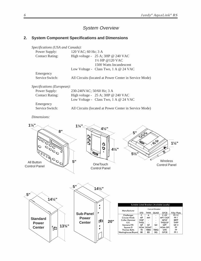
2. System Component Specifications and Dimensions
Specifications (USA and Canada):Power Supply: 120 VAC; 60 Hz; 3 AContact Rating: High voltage - 25 A; 3HP @ 240 VAC
1½ HP @120 VAC1500 Watts Incandescent
Low Voltage - Class Two, 1 A @ 24 VACEmergencyService Switch: All Circuits (located at Power Center in Service Mode)
Specifications (European):Power Supply: 230-240VAC; 50/60 Hz; 3 AContact Rating: High voltage - 25 A; 3HP @ 240 VAC
Low Voltage - Class Two, 1 A @ 24 VACEmergencyService Switch: All Circuits (located at Power Center in Service Mode)
Dimensions:
StandardPowerCenter
5"14½"
13¾"
8"
5"
1¼"
5½"
1½"
5"4½"
4½"
1¼"
Sub-PanelPowerCenter 20"
14½"5"
All ButtonControl Panel
OneTouchControl Panel
WirelessControl Panel

Jandy® Controls 7
Plumbing for Pool and Spa Combination
System Overview
3. Basic Plumbing3.1. This is a simplified version of a standard plumbing setup for a pool and spa that share the
same filter pump, filter, and heater. The intake and return JVA’s turn simultaneously so whenthe Spa button is pressed on the AquaLink RS Control Panel, water circulation switchesbetween pool and spa (consult the Jandy JVA Installation Manual to ensure that the JVA’sare "in sync" and rotate properly). Please consult the Jandy Valve Plumbing Manual forfurther examples of pool/spa plumbing.
Please note that if you have a pool only or a spa only, the diagram does not apply, and if yourpool and spa have separate sets of equipment, you should install an AquaLink RS DualEquipment model, designed to control separate equipment sets.
Note: When the filter system is shared (a Pool/Spa Combo), the spa water must be able tooverflow back to the pool.
Heater
Filter
FilterPump
Pool Drain
Spa DrainSpa ReturnPool Return
CheckValve
SpaMake-up
CheckValve
Heat Pump
SkimmersSkimmers
From Solar To Solar

8 Jandy® AquaLink® RS
Non-Booster Pump Pool Cleaner Plumbing
System Overview
Heater
FilterFilterPump
Pool Intake Spa Intake
Spa ReturnPool Return
CheckValve
Spa Make-up
EnergyFilter
CleanerLine
Booster Pump Pool Cleaner Plumbing
Heater
Filter FilterPump
Pool Intake Spa IntakeSpa ReturnPool Return
CheckValve
Spa Make-upBoosterPump

Jandy® Controls 9
Installation
1. Power Center Mounting1.1. The Power Center should be located at or near the equipment pad. Locate the Power Center at
least five (5) feet or more away from pool/spa and five (5) feet off the ground. All national,state, and local codes are applicable.
1.2. Use the mounting brackets and instructions provided with the Standard Power Center and/orSub-Panel Power Center.
1.3. Sub-Panel Power Centers have special code requirements. Be sure to follow all applicablelocal and state codes to insure safe installation.
2. High Voltage Wiring2.1. System Power- Depending on the amount of equipment being controlled, run ½" or ¾"
conduit from the power supply panel to the bottom of the Power Center. If you are usingthe Sub-Panel Power Center, wire power to the appropriate breakers. Pull in appropriate wirefor equipment. Each piece of equipment requires its own high voltage relay. Connect 120volts to the Power Center terminals. Connect equipment ground(s).
Filter Pump Relay Aux. 3 Relay
Ground
Neu
tral
Filter Pump Relay Aux. 3 Relay
Standard Power Center
Transformer
Earth Ground
Breaker Panel
To 120 VACBreaker
Neutral
BlackWhite
Wire nut to 120 VAC power
Transformer
Sub-Panel Power Center
Earth Ground
BlackWhite
BlackWhite
Prim
ary
Lo
w v
olta
ge
race
way
, d
o n
ot
run
hig
h v
olta
ge
in t
his
co
mpa
rtm
ent
BlackWhite Ground
From MainPower
Lo
w v
olta
ge
race
way
, d
o n
ot
run
hig
h v
olta
ge
in t
his
co
mpa
rtm
ent
Pri
mar
y
10 Jandy® AquaLink® RS
Filter Pump Relay Aux. 3 Relay
Load
2
Line
2
Load
1
Line
1
Ground
Neu
tra
l
PR
IMA
RY
24 V
AC
SE
CO
ND
AR
Y
BondingLug
Installation
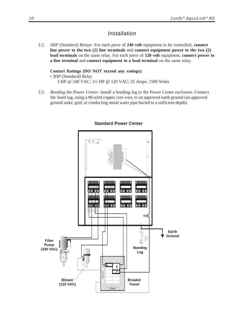
2.2. 3HP (Standard) Relays- For each piece of 240 volt equipment to be controlled, connectline power to the two (2) line terminals and connect equipment power to the two (2)load terminals on the same relay. For each piece of 120 volt equipment, connect power toa line terminal and connect equipment to a load terminal on the same relay.
Contact Ratings (DO NOT exceed any ratings):• 3HP (Standard) Relay
3 HP @ 240 VAC; 1½ HP @ 120 VAC; 25 Amps; 1500 Watts
2.3. Bonding the Power Center- Install a bonding lug to the Power Center enclosure. Connectthe bond lug, using a #8 solid copper core wire, to an approved earth ground (an approvedground stake, grid, or conducting metal water pipe buried to a sufficient depth).
EarthGround
BreakerPanel
Blower(120 VAC)
FilterPump
(240 VAC)
Standard Power Center

Jandy® Controls 11
Installation
2.4. Underwater Lighting- High voltage pool/spa lights require Ground Fault Circuit Interrupter(GFCI) protection. To meet code requirements the pool/spa light must be connected directly tothe GFCI. Do not use a GFCI circuit breaker.2.4.1. For a Standard Power Center, install a GFCI receptacle next to the breaker panel.
For a Sub-Panel Power Center install a GFCI receptacle in the Power Center (usethe knockout provided on the right side of the Sub-Panel Power Center).
2.4.2. Connect neutral and hot wire (from circuit breaker) to the LINE side of the GFCI.2.4.3. Connect neutral (white wire) and the hot (black wire) from the light to the LOAD
side of the GFCI.2.4.4. Connect ground from the light to the grounding bar inside the Power Center.
O PTIO N AL
GFCIOutlet
O PTIO N AL
GFCIOutlet
(Optional)
12 Jandy® AquaLink® RS
Installation
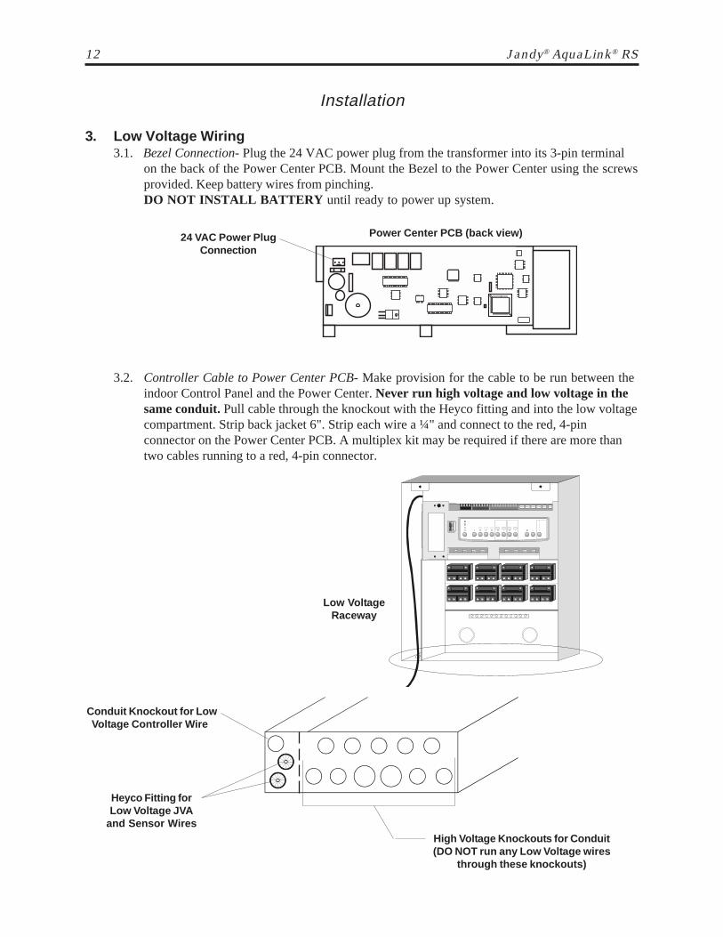
3. Low Voltage Wiring3.1. Bezel Connection- Plug the 24 VAC power plug from the transformer into its 3-pin terminal
on the back of the Power Center PCB. Mount the Bezel to the Power Center using the screwsprovided. Keep battery wires from pinching.DO NOT INSTALL BATTERY until ready to power up system.
Low VoltageRaceway
Conduit Knockout for LowVoltage Controller Wire
Heyco Fitting forLow Voltage JVA
and Sensor WiresHigh Voltage Knockouts for Conduit(DO NOT run any Low Voltage wires
through these knockouts)
3.2. Controller Cable to Power Center PCB- Make provision for the cable to be run between theindoor Control Panel and the Power Center. Never run high voltage and low voltage in thesame conduit. Pull cable through the knockout with the Heyco fitting and into the low voltagecompartment. Strip back jacket 6". Strip each wire a ¼" and connect to the red, 4-pinconnector on the Power Center PCB. A multiplex kit may be required if there are more thantwo cables running to a red, 4-pin connector.
24 VAC Power PlugConnection
Power Center PCB (back view)
Jandy® Controls 13
Installation
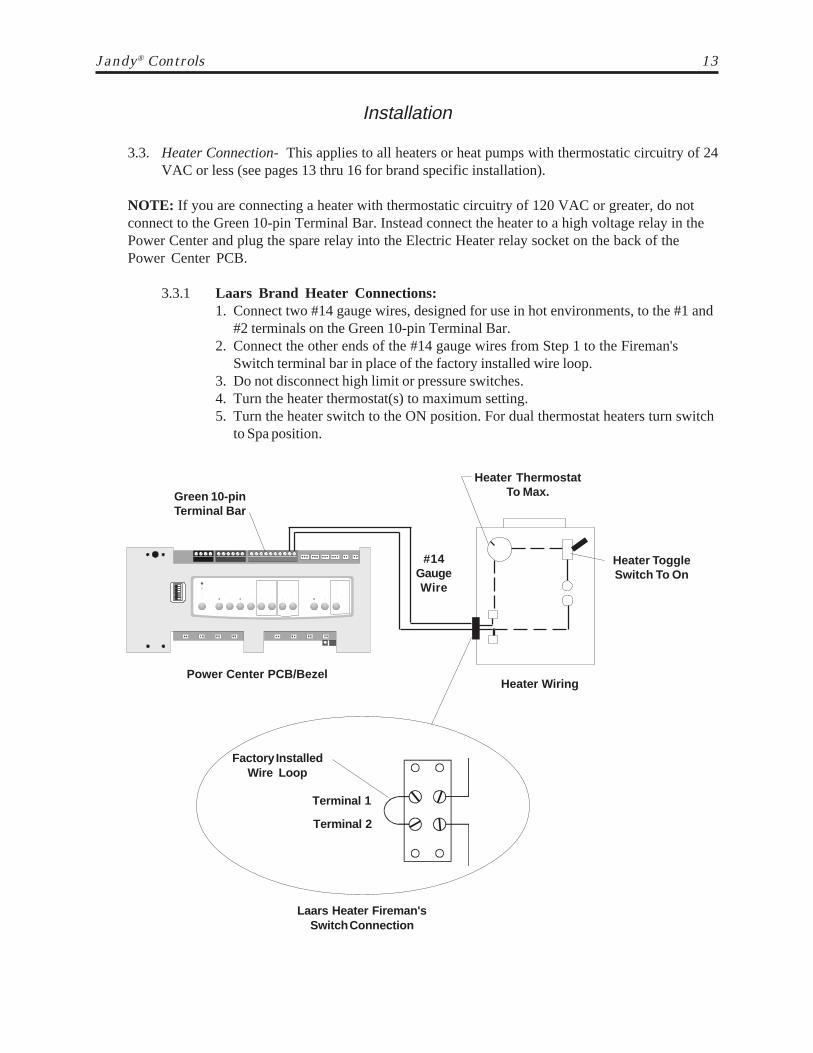
3.3. Heater Connection- This applies to all heaters or heat pumps with thermostatic circuitry of 24VAC or less (see pages 13 thru 16 for brand specific installation).
NOTE: If you are connecting a heater with thermostatic circuitry of 120 VAC or greater, do notconnect to the Green 10-pin Terminal Bar. Instead connect the heater to a high voltage relay in thePower Center and plug the spare relay into the Electric Heater relay socket on the back of thePower Center PCB.
3.3.1 Laars Brand Heater Connections:1. Connect two #14 gauge wires, designed for use in hot environments, to the #1 and
#2 terminals on the Green 10-pin Terminal Bar.2. Connect the other ends of the #14 gauge wires from Step 1 to the Fireman's
Switch terminal bar in place of the factory installed wire loop.3. Do not disconnect high limit or pressure switches.4. Turn the heater thermostat(s) to maximum setting.5. Turn the heater switch to the ON position. For dual thermostat heaters turn switch
to Spa position.
Power Center PCB/BezelHeater Wiring
#14GaugeWire
Green 10-pinTerminal Bar
Heater ThermostatTo Max.
Heater ToggleSwitch To On
Terminal 1
Terminal 2
Laars Heater Fireman'sSwitch Connection
Factory InstalledWire Loop
14 Jandy® AquaLink® RS
LX GUI
OPTIONAL
4 3 2 1
43
21
OR
REDBLKYELGRN
RS PowerCenter4-Conductor Wire
GR
NY
EL
BL
KR
ED
Installation
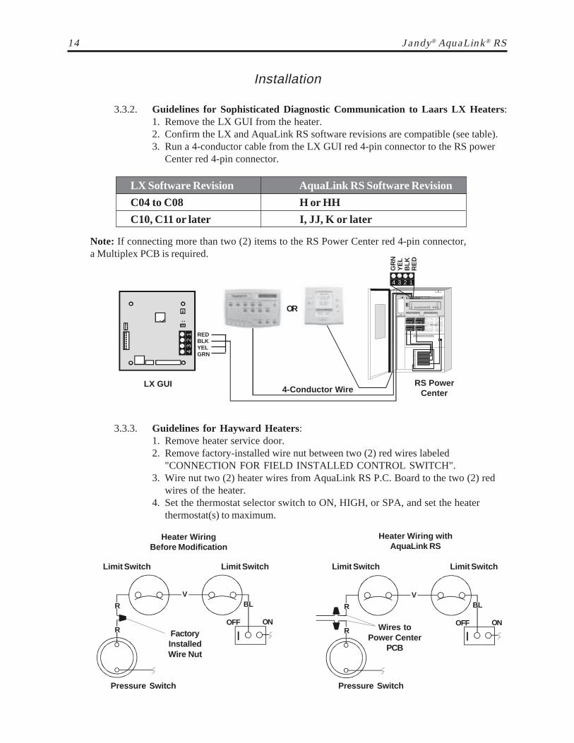
3.3.2. Guidelines for Sophisticated Diagnostic Communication to Laars LX Heaters:1. Remove the LX GUI from the heater.2. Confirm the LX and AquaLink RS software revisions are compatible (see table).3. Run a 4-conductor cable from the LX GUI red 4-pin connector to the RS power
Center red 4-pin connector.
Note: If connecting more than two (2) items to the RS Power Center red 4-pin connector,a Multiplex PCB is required.
Limit Switch
Heater WiringBefore Modification
Heater Wiring withAquaLink RS
FactoryInstalledWire Nut
R
Limit Switch Limit Switch Limit Switch
R
V
OFF ON
BL R
R
V
OFF ON
BL
Pressure Switch Pressure Switch
Wires toPower Center
PCB
3.3.3. Guidelines for Hayward Heaters:1. Remove heater service door.2. Remove factory-installed wire nut between two (2) red wires labeled
"CONNECTION FOR FIELD INSTALLED CONTROL SWITCH".3. Wire nut two (2) heater wires from AquaLink RS P.C. Board to the two (2) red
wires of the heater.4. Set the thermostat selector switch to ON, HIGH, or SPA, and set the heater
thermostat(s) to maximum.
LX Software Revision AquaLink RS Software Revision
C04 to C08 H or HH
C10, C11 or later I, JJ, K or later
Jandy® Controls 15
VIO
Heater WiringBefore Modification
Heater Wiring withAquaLink RS
BLK
BLK
RED
VIO
BLK
BLK
RED
Wires fromPower Center
PCB
Installation
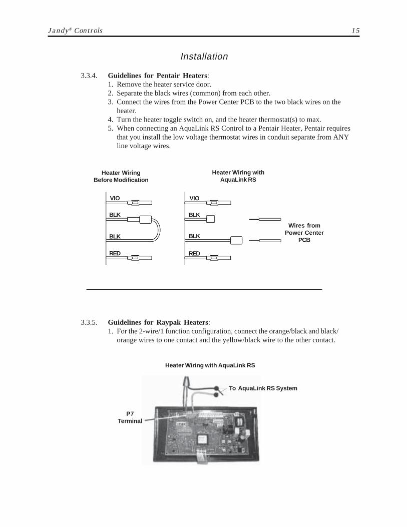
3.3.4. Guidelines for Pentair Heaters:1. Remove the heater service door.2. Separate the black wires (common) from each other.3. Connect the wires from the Power Center PCB to the two black wires on the
heater.4. Turn the heater toggle switch on, and the heater thermostat(s) to max.5. When connecting an AquaLink RS Control to a Pentair Heater, Pentair requires
that you install the low voltage thermostat wires in conduit separate from ANYline voltage wires.
P7Terminal
To AquaLink RS System
Heater Wiring with AquaLink RS
3.3.5. Guidelines for Raypak Heaters:1. For the 2-wire/1 function configuration, connect the orange/black and black/
orange wires to one contact and the yellow/black wire to the other contact.

16 Jandy® AquaLink® RS
Water Temperature Sensor
Freeze/Air Temperature Sensor Solar Temperature Sensor
Green 10-Pin Terminal Bar (Wiring for a Pool/Spa Combination)
3.4. Temperature Sensors-3.4.1. Drill 3/8" hole in pipe between filter pump and filter and install the Water
Temperature Sensor per instructions (make certain the o-ring is in place).3.4.2. Install Air Temperature Sensor outside the Power Center can, not in direct
sunlight and away from motors and other heat sources.3.4.3. Install Solar Temperature Sensor (optional) adjacent to solar panels.
Note: if a solar sensor (or a 2.2k Ohms resistor) is not installed, the solar button can be labeledand used as an extra auxiliary.
3.4.4. Run the wire to the Power Center, through the low voltage raceway. Cut off excesswire and strip each wire ¼". Connect sensor wires to the Green 10-pin terminal bar.
Installation
3.3.6. Guidelines for a Gas Heater in addition to a Heat Pump:1. Install a fixed resistor, with a value of 2.2k Ohms, in the solar sensor terminals
#3 and #4 of the green 10-pin terminal bar of the AquaLink RS Power Center(see figure below). The RS will auto-relabel Solar as Heat Pump within 24 hours.
2. The Solar/Heat Pump Button will activate the heat pump and the Pool and/or SpaHeater Buttons will activate the gas heater. In this manner the pool or spa can beheated by the heat pump, the gas heater or both.
TM
4 3 2 1 6 5 4 3 2 1
Battery(9Volt)
Gas Heater
Standard HighVoltage Relay
HeatPump
Green- EnabledRed- On
2.2 K OhmsResistor- in
Solar SensorTerminals
Gas HeaterConnections
Terminals 1 and 2
Fireman'sSwitch
From FusibleLink
To PressureSwitch
LED will notcome on forHeat Pump
Jandy® Controls 17
Installation
3.5. Jandy Valve Actuators- Mount the JVA's according to the JVA Installation Manual.JVA cable is type SJW-A marked water resistant class 3 cable and does not requireconduit. Knockouts and Heyco fittings are provided in the Low Voltage Raceway.
3.5.1. Route the JVA wire to the Power Center.3.5.2. Run the wire through the low voltage raceway and plug the JVA connectors into their
proper sockets (see Wiring Diagram in Appendix). Verify that the JVA on the suctionplumbing is connected to the Intake JVA Socket, and the discharge plumbing isconnected to the Return JVA Socket.
Note: Do not coil the JVA wires inside Power Center. To shorten the wire, remove theJVA cover and undo the wire nuts. Shorten, strip, and reconnect.
3.5.3. For alternate plumbing configurations the JVA cam settings can be adjusted asneeded. See JVA Installation Manual, Cam Setting Chart for proper settings.
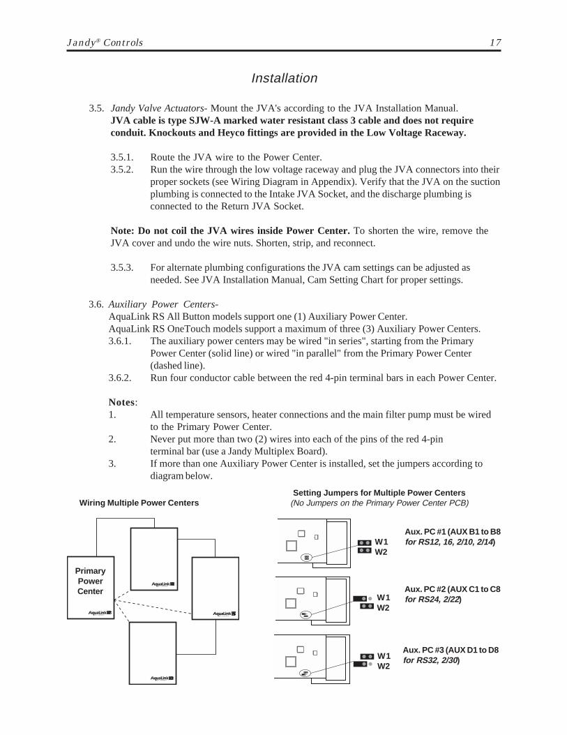
3.6. Auxiliary Power Centers-AquaLink RS All Button models support one (1) Auxiliary Power Center.AquaLink RS OneTouch models support a maximum of three (3) Auxiliary Power Centers.3.6.1. The auxiliary power centers may be wired "in series", starting from the Primary
Power Center (solid line) or wired "in parallel" from the Primary Power Center(dashed line).
3.6.2. Run four conductor cable between the red 4-pin terminal bars in each Power Center.
Notes:1. All temperature sensors, heater connections and the main filter pump must be wired
to the Primary Power Center.2. Never put more than two (2) wires into each of the pins of the red 4-pin
terminal bar (use a Jandy Multiplex Board).3. If more than one Auxiliary Power Center is installed, set the jumpers according to
diagram below.
PrimaryPowerCenter
Wiring Multiple Power Centers
Aux. PC #1 (AUX B1 to B8for RS12, 16, 2/10, 2/14)W1
W2
Setting Jumpers for Multiple Power Centers(No Jumpers on the Primary Power Center PCB)
Aux. PC #2 (AUX C1 to C8for RS24, 2/22)
Aux. PC #3 (AUX D1 to D8for RS32, 2/30)
W1W2
W1W2

18 Jandy® AquaLink® RS
3.7.2. Multiple AquaLink RS All Button Controller Installation:The AquaLink RS allows each system to support a maximum of 4 indoorcontrollers. The controllers may be wired "in series" starting from the first controller(Solid Line), or wired "in parallel" from the AquaLink RS Power Center (DottedLine), or any combination of the two (i.e. any number of Indoor Controllers and/orPower Centers can be connected via the red 4-pin terminal bar in any combination of"series" or "parallel" wiring).
Note: Voltage drop can be a problem when connecting more than one controller. Use largewire (16 or 18 AWG) to minimize voltage loss.
TM
TM
TM TM
MountingScrew Holes
4 3 2 1
4-Conductor CableAccess Hole
Back of Control Panel Inside the Front Control Panel
Red 4-Pin ConnectorG
reen
Yel
low
Bla
ckR
ed
Installation
3.7. All Button Control Panel-3.7.1. Single Indoor Control Panel:
1. With the aid of the homeowner, find the best location for the Control Panel.2. Open the Indoor Control Panel Assembly by pressing in on the tab at the bottom.
Place the back of the control panel against the wall. Level the back of the controlpanel and mark the three (3) mounting screw holes and the cable access hole.
3. Drill ¼" holes at the three (3) mounting screw marks and insert the plastic anchors.Drill a 1¼" (min.) to 2" (max.) hole for cable access.
4. Mount the back of the control panel housing to the wall and secure in place.5. Pull the 4-conductor cable through the access hole and tie a loose knot to prevent
the cable from slipping back through the access hole. Strip cable jacket 6", andeach individual wire ¼".
6. Remove the red 4-pin terminal bar from the control panel PCB. Connect the 4conductor cable to the red 4-pin terminal bar. Reconnect the red 4-pin terminalbar back to the Control Panel PCB.
7. Hang the Control Panel front over the two tabs at the top of the control panelback. Swing the bottom of the Control Panel front down and snap into place.
Tab
Jandy® Controls 19
W2W1
Second ControllerFirst Controller
Third Controller Fourth Controller
W2W1
W2W1
W2W1
Yello
wG
reen
Bla
ckR
ed
W2W1
Multiple Control Panels
Installation
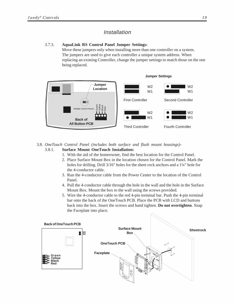
3.7.3. AquaLink RS Control Panel Jumper Settings:Move these jumpers only when installing more than one controller on a system.The jumpers are used to give each controller a unique system address. Whenreplacing an existing Controller, change the jumper settings to match those on the onebeing replaced.
JumperLocation
Back ofAll Button PCB
Jumper Settings
3.8. OneTouch Control Panel (includes both surface and flush mount housings)-3.8.1. Surface Mount OneTouch Installation:
1. With the aid of the homeowner, find the best location for the Control Panel.2. Place Surface Mount Box in the location chosen for the Control Panel. Mark the
holes for drilling. Drill 3/16" holes for the sheet rock anchors and a 1¼" hole forthe 4-conductor cable.
3. Run the 4-conductor cable from the Power Center to the location of the ControlPanel.
4. Pull the 4-conductor cable through the hole in the wall and the hole in the SurfaceMount Box. Mount the box to the wall using the screws provided.
5. Wire the 4-conductor cable to the red 4-pin terminal bar. Push the 4-pin terminalbar onto the back of the OneTouch PCB. Place the PCB with LCD and buttonsback into the box. Insert the screws and hand tighten. Do not overtighten. Snapthe Faceplate into place.
Surface MountBox
OneTouch PCB
Faceplate
SheetrockW2W1
Back of OneTouch PCB
GreenYellowBlackRed
43
21
20 Jandy® AquaLink® RS
Installation
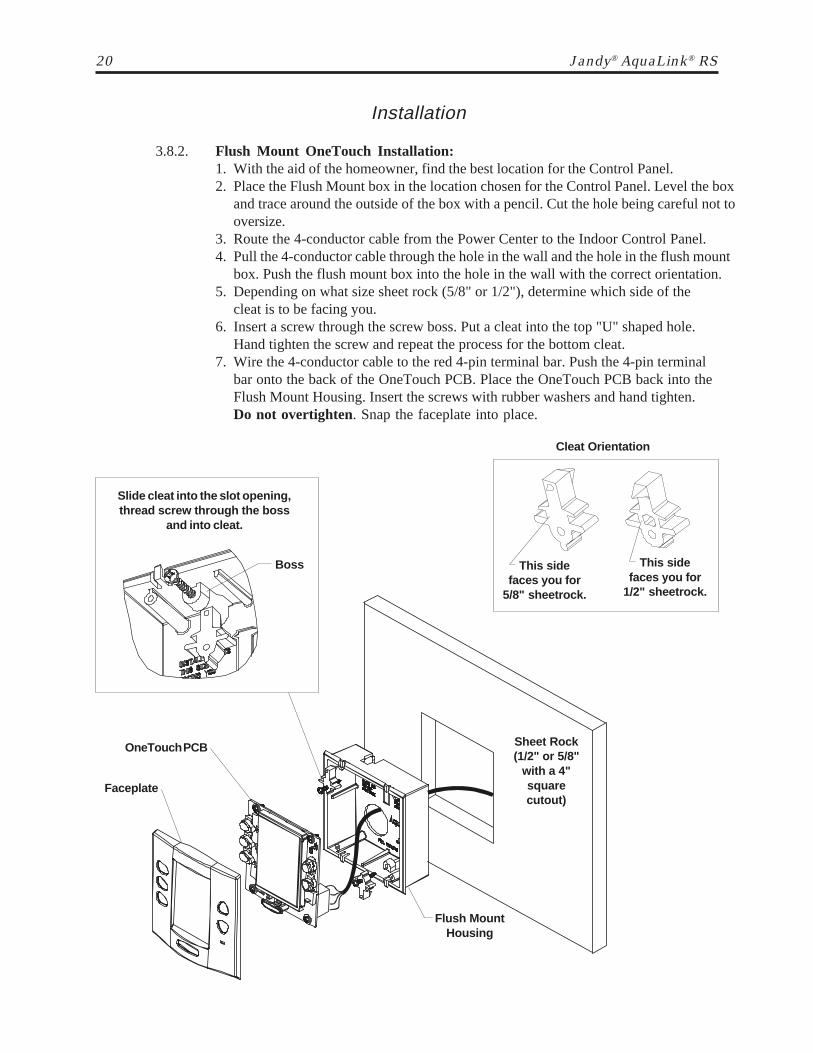
3.8.2. Flush Mount OneTouch Installation:1. With the aid of the homeowner, find the best location for the Control Panel.2. Place the Flush Mount box in the location chosen for the Control Panel. Level the box
and trace around the outside of the box with a pencil. Cut the hole being careful not tooversize.
3. Route the 4-conductor cable from the Power Center to the Indoor Control Panel.4. Pull the 4-conductor cable through the hole in the wall and the hole in the flush mount
box. Push the flush mount box into the hole in the wall with the correct orientation.5. Depending on what size sheet rock (5/8" or 1/2"), determine which side of the
cleat is to be facing you.6. Insert a screw through the screw boss. Put a cleat into the top "U" shaped hole.
Hand tighten the screw and repeat the process for the bottom cleat.7. Wire the 4-conductor cable to the red 4-pin terminal bar. Push the 4-pin terminal
bar onto the back of the OneTouch PCB. Place the OneTouch PCB back into theFlush Mount Housing. Insert the screws with rubber washers and hand tighten.Do not overtighten. Snap the faceplate into place.
Sheet Rock(1/2" or 5/8"
with a 4"squarecutout)
Flush MountHousing
Slide cleat into the slot opening,thread screw through the boss
and into cleat.
Boss
Cleat Orientation
This sidefaces you for
5/8" sheetrock.
This sidefaces you for
1/2" sheetrock.
Faceplate
OneTouch PCB

Jandy® Controls 21
Installation
3.8.3. Multiple AquaLink RS OneTouch Control Panel Installation:The AquaLink RS allows each system to support a maximum of 4 indoorcontrollers. The controllers may be wired "in series" starting from the first controller(Solid Line), or wired "in parallel" from the AquaLink RS Power Center (DottedLine), or any combination of the two (i.e. any number of Indoor Controllers and/orPower Centers can be connected via the red 4-pin terminal bar in any combination of"series" or "parallel" wiring).
Note: Voltage drop can be a problem when connecting more than one controller. Use largewire (16 or 18 AWG) to minimize voltage loss or install the optional Booster Power Supply Kit(part #7477).
W2W1
Second ControllerFirst Controller
Third Controller Fourth Controller
W2W1
W2W1
W2W1
W2W1
JumperLocation
Back ofOneTouch
PCB
Jumper Settings
3.8.4. AquaLink RS OneTouch Control Panel Jumper Settings:Move these jumpers only when installing more than one controller on a system.The jumpers are used to give each controller a unique system address. Whenreplacing an existing Controller, change the jumper settings to match those on the onebeing replaced.

22 Jandy® AquaLink® RS
Installation
3.9. Wireless OneTouch Control Panel-Installation Considerations- The transceivers will transmit through walls and around corners.Steel framing, aluminum siding, wrought iron, cyclone fences, leaded glass may , microwaveovens, and other 2.4 GHz frequency items may inhibit/prevent communication between theWireless AquaLink RS Control Panel and the Power Center. The transceivers do not requireline of sight to communicate. To optimize communication, locate transceivers to minimizeinterference. The Battery Wireless AquaLink RS system requires OneTouch Indoor PCBrevision "E" and firmware revision "B11" in order to work properly.
3.9.1. Outdoor Transceiver J-box Installation:1. Turn off all power to the Power Center.2. Mount the Outdoor Transceiver J-box at least 5' above the ground and at least 8'
from an air blower.3. Remove the cover from the Transceiver J-box. Use the template provided to drill
the mounting holes. Mount the Transceiver J-box and replace the cover.4. Open the door to the Power Center and remove the dead panel.5. Feed the four conductor wire into the Power Center through the low voltage
raceway.6. Cut off the excess wire. Strip the jacket back 6" and strip the individual wires
approximately ¼". Connect the four conductor wire to the red terminal bar on thePower Center PCB.
7. Install the dead panel to the Power Center and restore all power.
J-boxTransceiver
5'
Low Voltage Raceway
Minimum 8' AirBlower
PowerCenter
When not in use, turnthe ON/OFF Switch tothe off position.
Power Supply/Charger Cord
3 Y
ello
w
1 R
ed
2 B
lack
4 G
reen
Red 4-PinTerminal Bar
3.9.2. Indoor Control Panel Installation:1. Connect the transformer to the back of the control panel.2. Plug the transformer into a wall socket.3. Charge for 24 hours before removing the Power Supply/Charger (the
system is operational while charging).
GroundLevel

Jandy® Controls 23
Installation
3.9.3. Changing the Transmission Code:If your AquaLink RS system is turning items on or off at odd times it may be theresult of another AquaLink RS Wireless Controller in close proximity using the sameor similar code. To prevent unwanted operation, the code for your AquaLink RSWireless system can be personalized. Except for dip switch #8, both the PowerCenter Transceiver and the Control Panel Transceiver must be set to the same code.The Indoor Control Panel Transceiver dip switch #8 must be OFF and the PowerCenter Transceiver dip switch #8 must be ON.1. Go to the Indoor Control Panel and remove the screws to expose the transceiver
PCB.2. Locate the small set of dip switches on the Control Panel PCB. Except for dip
switch #8, turn on one or more dip switches. Important- before installing theControl Panel cover, press the reset button (SW1). Note which switchesyou have turned on then reinstall the cover and screws.
3. At the Outdoor Transceiver J-box, remove the cover to expose the TransceiverPCB and set the dip switches (except #8) to the same settings as the ControlPanel Transceiver PCB that is in the house. Important- before installingthe J-box cover, press the reset button (SW1). Close the cover and test thesystem.
Always OFF
If any DIP Switch is moved,you must press SW1 toestablish communication(may need to press morethan one time).
SW1
IndoorControlPanelTransceiverPCB
Power Center J-Box
Always ON
If any DIP Switch is moved,you must press SW1 toestablish communication(may need to press morethan one time).
SW1
PowerCenterTransceiverPCB
Indoor Control Panel
24 Jandy® AquaLink® RS
System Startup
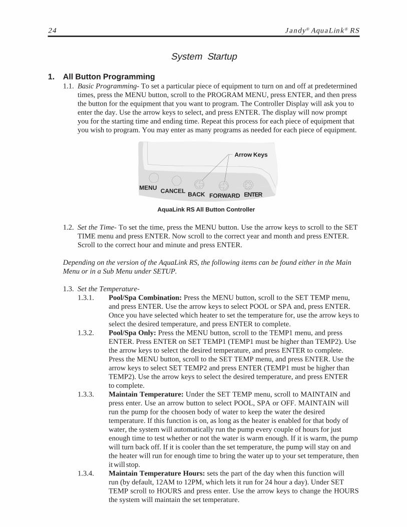
1. All Button Programming1.1. Basic Programming- To set a particular piece of equipment to turn on and off at predetermined
times, press the MENU button, scroll to the PROGRAM MENU, press ENTER, and then pressthe button for the equipment that you want to program. The Controller Display will ask you toenter the day. Use the arrow keys to select, and press ENTER. The display will now promptyou for the starting time and ending time. Repeat this process for each piece of equipment thatyou wish to program. You may enter as many programs as needed for each piece of equipment.
Arrow Keys
AquaLink RS All Button Controller
1.2. Set the Time- To set the time, press the MENU button. Use the arrow keys to scroll to the SETTIME menu and press ENTER. Now scroll to the correct year and month and press ENTER.Scroll to the correct hour and minute and press ENTER.
Depending on the version of the AquaLink RS, the following items can be found either in the MainMenu or in a Sub Menu under SETUP.
1.3. Set the Temperature-1.3.1. Pool/Spa Combination: Press the MENU button, scroll to the SET TEMP menu,
and press ENTER. Use the arrow keys to select POOL or SPA and, press ENTER.Once you have selected which heater to set the temperature for, use the arrow keys toselect the desired temperature, and press ENTER to complete.
1.3.2. Pool/Spa Only: Press the MENU button, scroll to the TEMP1 menu, and pressENTER. Press ENTER on SET TEMP1 (TEMP1 must be higher than TEMP2). Usethe arrow keys to select the desired temperature, and press ENTER to complete.Press the MENU button, scroll to the SET TEMP menu, and press ENTER. Use thearrow keys to select SET TEMP2 and press ENTER (TEMP1 must be higher thanTEMP2). Use the arrow keys to select the desired temperature, and press ENTERto complete.
1.3.3. Maintain Temperature: Under the SET TEMP menu, scroll to MAINTAIN andpress enter. Use an arrow button to select POOL, SPA or OFF. MAINTAIN willrun the pump for the choosen body of water to keep the water the desiredtemperature. If this function is on, as long as the heater is enabled for that body ofwater, the system will automatically run the pump every couple of hours for justenough time to test whether or not the water is warm enough. If it is warm, the pumpwill turn back off. If it is cooler than the set temperature, the pump will stay on andthe heater will run for enough time to bring the water up to your set temperature, thenit will stop.
1.3.4. Maintain Temperature Hours: sets the part of the day when this function willrun (by default, 12AM to 12PM, which lets it run for 24 hour a day). Under SETTEMP scroll to HOURS and press enter. Use the arrow keys to change the HOURSthe system will maintain the set temperature.
MENU CANCEL BACK FORWARD ENTER
Jandy® Controls 25
System Startup
1.4. Label Auxiliary Functions- Press the MENU button, scroll to SYSTEM SETUP and pressENTER. Scroll to the LABEL AUX menu and press ENTER. Press the button (on thecontroller) to be labeled (example: AUX1). Scroll to the desired label and press ENTER.Repeat for all functions. Note 1: the labels TIMED AUX, AIR BLOWER, and FILL LINE are30 minute timed functions. Note 2: If DIP switch 1,2 or 3 are on, auxiliaries 1, 2 and 3 arelabeled CLEANER, LOW SPEED and SPILLOVER respectively and cannot be relabeled.
1.5. Set Freeze Protection- The AquaLink RS Freeze Protection senses when the air temperaturefalls below 38° F and will automatically turn on the filter pump to circulate the water. To addfreeze protection to other equipment press the MENU button. Scroll to SYSTEM SETUP andpress ENTER, then scroll to FRZ PROTECT and press ENTER. Press the button for theequipment you want to protect.
1.6. Assign JVAs- The assign JVA menu lets you assign Jandy Valve Actuators (JVA) to anyauxiliary button. This means that whenever you press that auxiliary button, a valve turns. Onpool/spa combination models, there are two JVAs that can be assigned to auxiliary buttons: theCleaner JVA and the Solar JVA (unless the solar function is installed). On pool only/spa onlymodels, there are four JVAs available. The AquaLink RS installer must set up these JVAs forthis feature to operate correctly. Assigning JVAs lets the owner control certain features likediverting water to a waterfall or bank of spa jets. To assign JVA values, press the MENU button. Use the arrow keys to scroll to SYSTEMSETUP, press ENTER. Use the arrow keys to scroll to ASSIGN JVA menu and press ENTER.The AquaLink RS display will read CLEANER JVA. If both JVAs are being used, you will notbe able to use this menu. Use the arrow keys to choose among the JVAs listed. When the JVA you want to assign to anauxiliary is displayed, press ENTER. The AquaLink RS display will read SELECT AUX TO ASSIGN JVA TO. Press the button ofthe auxiliary you want to activate the JVA.
2. All Button Reset and Display Messages2.1. Reviewing- To review equipment, press the MENU button, then use the FORWARD arrow key
to scroll to the REVIEW menu. Press ENTER, use the arrow keys to scroll to the item you wishto review, and press ENTER again.
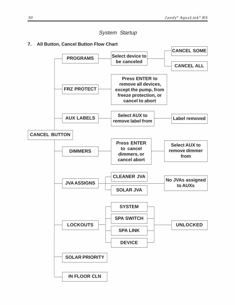
2.2. Canceling Items- If you make a mistake in programming or you want to change, for example,the ON/OFF times for a specific device, you can cancel programs for that piece of equipment.For example, to cancel a dimmer, press the CANCEL button; use the arrow keys toadvance to DIMMERS and press ENTER. The AquaLink RS display will prompt you to selectan Aux. Press the button of the auxiliary for which you want to cancel the dimmer.If you want to cancel a JVA assignment, first press the CANCEL button. Use the arrowkeys to scroll to JVA ASSIGNS and press ENTER. The AquaLink RS display will readCLEANER JVA. Use the arrow keys to toggle between JVAs to cancel. When the JVAassignment that you want to cancel is displayed, press ENTER. The AquaLink RS display willread PRESS ENTER TO CANCEL JVA ASSIGNMENT, OR CANCEL TO ABORT. PressENTER to cancel the JVA assignment, or press CANCEL to abort.
2.3. Resetting the System- To remove all labeling, programming, assignments, and temperaturesettings, press the MENU button, use the arrow keys to scroll to SYSTEM SETUP and pressENTER. Scroll to CLEAR MEMORY and press ENTER.

26 Jandy® AquaLink® RS
3.2. Set the Time- To set the time, highlight the MENU/HELP and press SELECT. Highlight SETTIME and press SELECT. Use the UP or DOWN button to set the values. Press SELECT tocontinue.
The following items can be found either in the MENU/HELP or in a Sub Menu under SYSTEMSETUP.
3.3. Set the Temperature3.3.1. Pool/Spa Combination: Highlight MENU/HELP and press SELECT. Highlight
SET TEMP and press SELECT. Use the UP or DOWN button to highlight eitherPOOL or SPA and press SELECT. Use the UP or DOWN button to increase ordecrease the temperature and press SELECT. Use the BACK button to return to themain screen.
3.3.2. Pool/Spa Only: Highlight MENU/HELP and press SELECT. HighlightSET TEMP and press SELECT (TEMP1 must be higher than TEMP2). PressSELECT on TEMP1. Use the UP or DOWN button to increase or decrease thetemperature and press SELECT. Highlight TEMP2 and press SELECT. Use the UPor DOWN button to increase or decrease the temperature and press SELECT. Usethe BACK button to return to the main screen.
3.3.3. Maintain Temperature: In the SET TEMP menu, highlighting MAINTAIN andpressing select will turn on (or off) the MAINTAIN function. MAINTAIN will runthe pump for the choosen body of water to keep the water at the desiredtemperature. If this function is on, as long as the heater is enabled for that body ofwater, the system will automatically run the pump every couple of hours for justenough time to test whether or not the water is warm enough. If it is warm, the pumpwill turn back off. If it is cooler than the set temperature, the pump will stay on andthe heater will run for enough time to bring the water up to your set temperature, thenit will stop.
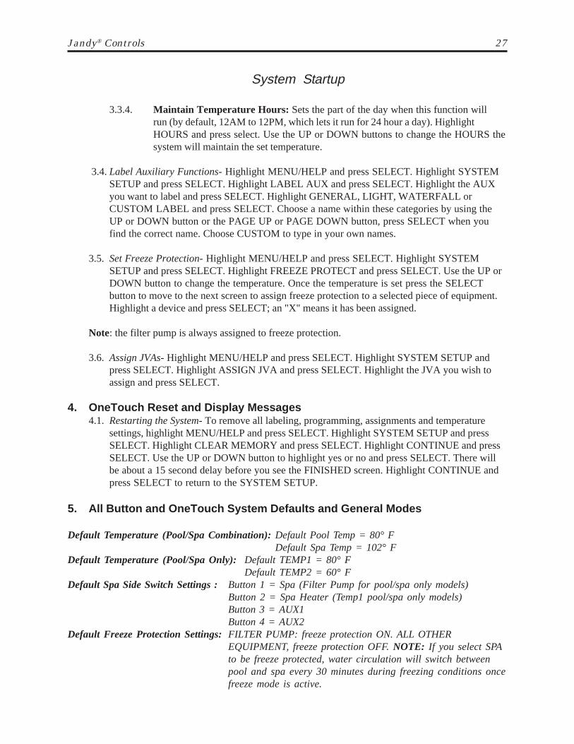
JANDY AquaLink RS
FILTER PUMP OFFAIR 79°
01/31/03 MON6:00 PM
EQUIPMENT ON/OFFONETOUCH ON/OFF
MENU / HELP
UP Button
DOWN Button
SELECT Button
Page Up
BACK
Page Down
Heater LEDGreen- heating enabledor up to temperatureRed- heater on andfiring
System Startup
3. OneTouch Programming3.1. Basic Programming- To set a particular piece of equipment to turn on and off at predetermined
times, highlight MENU/HELP and press SELECT. Highlight PROGRAM and press SELECT.Use the UP or DOWN buttons to highlight the equipment (e.g.: Filter Pump) then pressSELECT. Follow the on-screen prompts. Use the UP or DOWN buttons to pick each number,starting with ON hours, press SELECT to enter and move on to the next item to change,including picking what day(s) the program will run. If you make a mistake, use the BACKbutton to return to a number. If the program is already entered, highlight CHANGEPROGRAM and step through to the entry that should be corrected.
Jandy® Controls 27
System Startup
3.3.4. Maintain Temperature Hours: Sets the part of the day when this function willrun (by default, 12AM to 12PM, which lets it run for 24 hour a day). HighlightHOURS and press select. Use the UP or DOWN buttons to change the HOURS thesystem will maintain the set temperature.
3.4. Label Auxiliary Functions- Highlight MENU/HELP and press SELECT. Highlight SYSTEMSETUP and press SELECT. Highlight LABEL AUX and press SELECT. Highlight the AUXyou want to label and press SELECT. Highlight GENERAL, LIGHT, WATERFALL orCUSTOM LABEL and press SELECT. Choose a name within these categories by using theUP or DOWN button or the PAGE UP or PAGE DOWN button, press SELECT when youfind the correct name. Choose CUSTOM to type in your own names.
3.5. Set Freeze Protection- Highlight MENU/HELP and press SELECT. Highlight SYSTEMSETUP and press SELECT. Highlight FREEZE PROTECT and press SELECT. Use the UP orDOWN button to change the temperature. Once the temperature is set press the SELECTbutton to move to the next screen to assign freeze protection to a selected piece of equipment.Highlight a device and press SELECT; an "X" means it has been assigned.
Note: the filter pump is always assigned to freeze protection.
3.6. Assign JVAs- Highlight MENU/HELP and press SELECT. Highlight SYSTEM SETUP andpress SELECT. Highlight ASSIGN JVA and press SELECT. Highlight the JVA you wish toassign and press SELECT.
4. OneTouch Reset and Display Messages4.1. Restarting the System- To remove all labeling, programming, assignments and temperature
settings, highlight MENU/HELP and press SELECT. Highlight SYSTEM SETUP and pressSELECT. Highlight CLEAR MEMORY and press SELECT. Highlight CONTINUE and pressSELECT. Use the UP or DOWN button to highlight yes or no and press SELECT. There willbe about a 15 second delay before you see the FINISHED screen. Highlight CONTINUE andpress SELECT to return to the SYSTEM SETUP.
5. All Button and OneTouch System Defaults and General Modes
Default Temperature (Pool/Spa Combination): Default Pool Temp = 80° FDefault Spa Temp = 102° F
Default Temperature (Pool/Spa Only): Default TEMP1 = 80° FDefault TEMP2 = 60° F
Default Spa Side Switch Settings : Button 1 = Spa (Filter Pump for pool/spa only models)Button 2 = Spa Heater (Temp1 pool/spa only models)Button 3 = AUX1Button 4 = AUX2
Default Freeze Protection Settings: FILTER PUMP: freeze protection ON. ALL OTHEREQUIPMENT, freeze protection OFF. NOTE: If you select SPAto be freeze protected, water circulation will switch betweenpool and spa every 30 minutes during freezing conditions oncefreeze mode is active.

28 Jandy® AquaLink® RS
System Startup5.1. Power Center Service Switch-
5.1.1. AUTO Mode (automatic)-• The controller has complete control of all functions.• All programmed settings will operate.• All safety delays and equipment protection interlocks are operational.
5.1.2. SERVICE Mode-• The power center has complete control of all functions.• Service mode must be turned on/off at the power center.• No programmed settings will work.
CAUTION: In service mode, the safety interlocks for equipment protection are overridden.
5.1.3. TIMEOUT Mode-• The power center has complete control for three (3) hours.• After three (3) hours the system will return to AUTO mode.• Programmed on/off times will be overridden during the three (3) hours.• After the three (3) hour "time out", the system will resume any programmed
items that were overridden.5.1.4. Battery Backup- A nine-volt battery is located at the power center. Do not install the
battery in the power center until the system is ready to operate. Battery will drain ifpower is left off. Review DIAGNOSTICS in the SYSTEM SETUP section of themenu. The DIAGNOSTICS will indicate when the battery needs replacement.
Special Note to Startup PersonThe AquaLink RS allows you two (2) options for operating the pool equipment forthe first day of operation:
Option #1- Once all programming of equipment is completed, go to the power centerservice switch, press the button three (3) times. This will cycle the system fromAUTO to SERVICE to TIMEOUT and finally back to AUTO. The AquaLink RSwill now "look back" (review) all programs and turn on any equipment which isprogrammed to be on. Close the Power Center door. It will now operate asprogrammed.
Option #2- If you want the filter pump or cleaner to operate continually for the firstday, leave the power center service button in AUTO mode. Go to the indoorcontroller and press the AUX buttons for the equipment you want to run. Theequipment activated will now run continuously, ignoring the first programmed offtime, and will turn off at the programmed off time for the next day (only if a programhas been entered).

Jandy® Controls 29
System Startup
6. All Button, Menu Flow Chart
† Items Seen Only With Optional Equipment* Items Seen Only In Revision "K"** Not Available on Export Models
REVIEW
PROGRAMSelect
EquipmentOn All Days
On Weekends
On Weekdays
On Specific Day
SET TEMP
POOL TEMP
SET TIME Set Year, DayHour & Minute
LOCKOUTS
SYSTEM
SPA SWITCH
SPA LINK
DEVICEPGM GROUPGROUP A
DISPLAY LIGHT
ON
PROGRAMS
TEMP SET
SPA SWITCH
SPA LINK
FRZ PROTECT
AUX LABELS
DIMMERS
JVA ASSIGNS
SOLAR PRIORITY
ALL OFF TIME*
SET CHLORINE GEN† SET CHLORINEGEN %
SYSTEM SETUP
ALL OFF TIME*
ASSIGN JVA
TEMP CAL
DEGREES F/C
AIR TEMP
FRZ PROTECT
SPA LINK**
SPA SWITCH**
Main Label Menu(see Appendix
for expanded list)
SET DIMMERS**
SELECT EQUIPMENT
ALL OFF*
LABEL AUX
CHLORINE GEN HRS†
FLOWLINK SETUP* †
DAYLIGHT SAVINGS*
DIAGNOSTICS
CLEAR MEMORY
IN FLOOR CLN
SOLAR PRIORITY
PUMP LOCKOUT*
SET HOURS
FEATURE ON
SET BASELINE
ADJUST MIN
ADJUST MAX
ADJUST DIFF3 SWITCHES
2 SWITCHES
1 SWITCH
3 SPA LINKS
2 SPA LINKS
1 SPA LINK
OFF
ON Temp Settings
Assign Items
Warning! Clears All Memory
Diagnostic Readout
Choose JVA Choose Button
Celsius
Fahrenheit
Select Equipment
OFF
ON
OFF
ON
OFF
ON
OFF
ON
IN FLOOR CLN
SET TIME
Press Enter to Calibrate Use Arrow Buttons to Adjust Temperature
LOCKOUTS
FLOWLINK SETUP* †
30 Jandy® AquaLink® RS
System Startup
7. All Button, Cancel Button Flow Chart
CANCEL BUTTON
DIMMERSSelect AUX to
remove dimmerfrom
Press ENTERto cancel
dimmers, orcancel abort
JVA ASSIGNS
SOLAR JVA
CLEANER JVANo JVAs assigned
to AUXs
AUX LABELS Select AUX toremove label from Label removed
FRZ PROTECT
Press ENTER to remove all devices,
except the pump, fromfreeze protection, or
cancel to abort
PROGRAMS
CANCEL SOME
CANCEL ALL
Select device tobe canceled
SOLAR PRIORITY
IN FLOOR CLN
LOCKOUTS
DEVICE
SPA LINK
SPA SWITCH
SYSTEM
UNLOCKED

Jandy® Controls 31
System Startup
8. OneTouch, Menu Flow Chart
EQUIPMENT ON/OFF
ONETOUCH ON/OFF
SPA MODE
CLEAN MODE
ONETOUCH 3
ON
OFF
SELECT EQUIPMENT ON
OFF
MENU/HELP
HELP
KEYS
SERVICE
DIAGNOSTICS
PROGRAMSelect
Equipment ADD PROGRAM
SET TEMP
POOL HEAT
SPA HEAT
SET TIMESet Month, Day,
Year, & Time
DISPLAY LIGHT
ON
OFF
2 MIN. DELAY
LOCKOUTS
SYSTEM
SPA SWITCH
SPA LINK
DEVICES
LOCK
UNLK
SelectDevice
LOCK
UNLKPROGRAM
GROUP
GROUP A
GROUP B
SYSTEM SETUP
LABEL AUX
TEMP CALIBRATE
IN FLOOR CLEAN
SOLAR PRIORITY
ASSIGN JVA
DIMMERS**
SPA SWITCH**
SPA LINK**
PRODUCT INFO
CLEAR MEMORY
ONETOUCH
ONETOUCH 1
SelectDevice
ONETOUCH 2
ONETOUCH 3
SELECT NAME
CUSTOM NAME
SET DEVICESON
OFF
SelectDevice
GENERAL LABELS
LIGHT LABELS
WTRFALL LABELS
CUSTOM LABELS(Type Personalized
description)
SelectLabel
INTAKE
RETURN
CLEANER
SOLAR
1
23
1
23
OK
GO BACK
ENABLED
DISABLED
ENABLED
DISABLED
SET TEMP
FREEZE PROTECTION
AIR TEMP
DEGREES F/C
ENABLEDDISABLED
FAHRENHEIT
CELCIUS
SET TIME
FLOWLINK* †
BASELINE
DIFF
MIN
MAX
DAYLIGHT SAVINGS*ENABLED
DISABLED
PUMP LOCKOUT*ENABLED
DISABLED
DUSK SETUP*
DUSK CTRL
DURATIONTIME ADJUST
YOUR LOCATION
YOUR TIME ZONESET DEVICES
Choose Location
PACIFIC
MOUNTAIN
CENTRAL
EASTERN
Choose Equipment
SUPERCHLORINATE †
SET CHLORINE GENERATOR † Set % OFCHLORINE
SelectDevice
START
GO BACK
CHLORINEGENERATORHOURS†
SetTime
MAINTAIN*
HOURS*
OFF*
SPA*
POOL*
ON
OFF
SET TIME
ALL OFF TIME*
FEATURE
OFF TIME
OFF
ONSET TIME
ALL OFF
† Items Seen Only With Optional Equipment* Items Seen Only In Revision "K"** Not Available on Export Models

32 Jandy® AquaLink® RS
Troubleshooting
1. All Button and OneTouch Quick Troubleshooting Guide
Symptom Problem Possible Solution
Power Center override switchesoperate when in Service or TimeOut Mode, but the controlleris completely dead (no lights on,no display).
All LEDs are on at the controllerand the part # and revision letterof the controller software aredisplayed. The override switchesat the power center operate asthey should.
All LEDs are on at the controllerand the part # and revision letterare displayed, but overrideswitches at the power center donot operate at all.
Some buttons do not operate fromthe controller, nor from the powercenter override switches.
System locked up.
Programs do not run at thecorrect time.
Power supply problem.
Controller is not communicatingwith the power center PCB.
1. Damaged or improperlyinstalled PPD.
2. Damaged power center PCB.
Wrong PPD chip installed at thepower center PCB.
Microprocessor locked.
AquaLink does not displaycorrect time and date.
Check connection of the outsidetwo wires (red & green) of thefour conductor cable. If wiredcorrectly, check the voltagebetween these two wires. Voltagefor an All Button system should be7+ VDC and for a OneTouchsystem, 8+ VDC (use the highervoltage for a mixed system).
Check the two center wires (black& yellow) of the four conductorcable. Also check the installationof the PPD on the power centerPCB. If the PPD is not seatedcorrectly the system will notcommunicate.
1. Check alignment of the PPD.2. If PPD is installed correctly,
replace the power center PCB.
Check part number and revisionletter by pressing the reset buttonat the controller. The second partnumber and revision letter dis-played is for the PPD indicatingwhich model.
Turn off power to the system.Disconnect battery and turn onpower. Reconnect the battery andreset time and date.
At the controller set correct timeand date. In Diagnostics checkbattery level. If LOW BATTERYis displayed, replace battery toensure correct time and date aremaintained.
Jandy® Controls 33
Troubleshooting
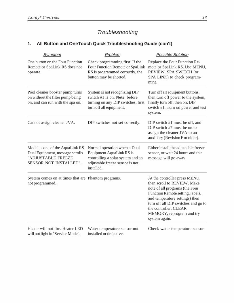
1. All Button and OneTouch Quick Troubleshooting Guide (con't)
Symptom Problem Possible Solution
One button on the Four FunctionRemote or SpaLink RS does notoperate.
Pool cleaner booster pump turnson without the filter pump beingon, and can run with the spa on.
Cannot assign cleaner JVA.
Model is one of the AquaLink RSDual Equipment, message scrolls"ADJUSTABLE FREEZESENSOR NOT INSTALLED".
System comes on at times that arenot programmed.
Heater will not fire. Heater LEDwill not light in "Service Mode".
Check programming first. If theFour Function Remote or SpaLinkRS is programmed correctly, thebutton may be shorted.
System is not recognizing DIPswitch #1 is on. Note: beforeturning on any DIP switches, firstturn off all equipment.
DIP switches not set correctly.
Normal operation when a DualEquipment AquaLink RS iscontrolling a solar system and anadjustable freeze sensor is notinstalled.
Phantom programs.
Water temperature sensor notinstalled or defective.
Replace the Four Function Re-mote or SpaLink RS. Use MENU,REVIEW, SPA SWITCH (orSPA LINK) to check program-ming.
Turn off all equipment buttons,then turn off power to the system,finally turn off, then on, DIPswitch #1. Turn on power and testsystem.
DIP switch #1 must be off, andDIP switch #7 must be on toassign the cleaner JVA to anauxiliary (Revision F or older).
Either install the adjustable freezesensor, or wait 24 hours and thismessage will go away.
At the controller press MENU,then scroll to REVIEW. Makenote of all programs (the FourFunction Remote setting, labels,and temperature settings) thenturn off all DIP switches and go tothe controller. CLEARMEMORY, reprogram and trysystem again.
Check water temperature sensor.
34 Jandy® AquaLink® RS
Troubleshooting
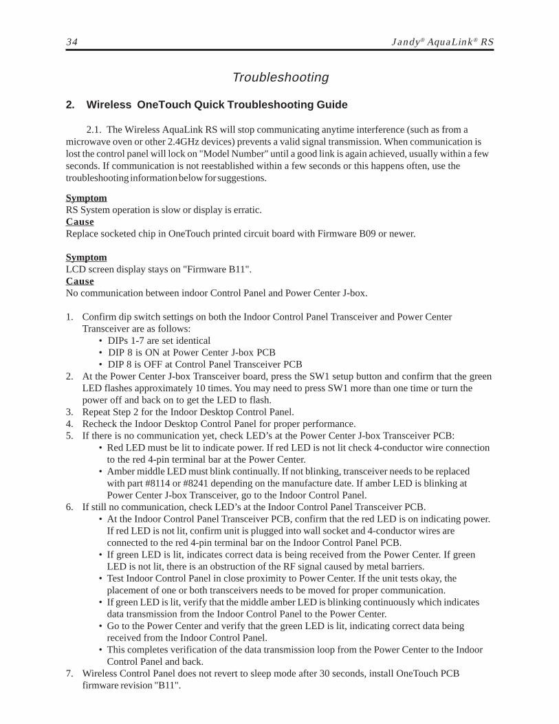
2. Wireless OneTouch Quick Troubleshooting Guide
2.1. The Wireless AquaLink RS will stop communicating anytime interference (such as from amicrowave oven or other 2.4GHz devices) prevents a valid signal transmission. When communication islost the control panel will lock on "Model Number" until a good link is again achieved, usually within a fewseconds. If communication is not reestablished within a few seconds or this happens often, use thetroubleshooting information below for suggestions.
SymptomRS System operation is slow or display is erratic.CauseReplace socketed chip in OneTouch printed circuit board with Firmware B09 or newer.
SymptomLCD screen display stays on "Firmware B11".CauseNo communication between indoor Control Panel and Power Center J-box.
1. Confirm dip switch settings on both the Indoor Control Panel Transceiver and Power CenterTransceiver are as follows:
• DIPs 1-7 are set identical• DIP 8 is ON at Power Center J-box PCB• DIP 8 is OFF at Control Panel Transceiver PCB
2. At the Power Center J-box Transceiver board, press the SW1 setup button and confirm that the greenLED flashes approximately 10 times. You may need to press SW1 more than one time or turn thepower off and back on to get the LED to flash.
3. Repeat Step 2 for the Indoor Desktop Control Panel.4. Recheck the Indoor Desktop Control Panel for proper performance.5. If there is no communication yet, check LED’s at the Power Center J-box Transceiver PCB:
• Red LED must be lit to indicate power. If red LED is not lit check 4-conductor wire connectionto the red 4-pin terminal bar at the Power Center.
• Amber middle LED must blink continually. If not blinking, transceiver needs to be replacedwith part #8114 or #8241 depending on the manufacture date. If amber LED is blinking atPower Center J-box Transceiver, go to the Indoor Control Panel.
6. If still no communication, check LED’s at the Indoor Control Panel Transceiver PCB.• At the Indoor Control Panel Transceiver PCB, confirm that the red LED is on indicating power.
If red LED is not lit, confirm unit is plugged into wall socket and 4-conductor wires areconnected to the red 4-pin terminal bar on the Indoor Control Panel PCB.
• If green LED is lit, indicates correct data is being received from the Power Center. If greenLED is not lit, there is an obstruction of the RF signal caused by metal barriers.
• Test Indoor Control Panel in close proximity to Power Center. If the unit tests okay, theplacement of one or both transceivers needs to be moved for proper communication.
• If green LED is lit, verify that the middle amber LED is blinking continuously which indicatesdata transmission from the Indoor Control Panel to the Power Center.
• Go to the Power Center and verify that the green LED is lit, indicating correct data beingreceived from the Indoor Control Panel.
• This completes verification of the data transmission loop from the Power Center to the IndoorControl Panel and back.
7. Wireless Control Panel does not revert to sleep mode after 30 seconds, install OneTouch PCBfirmware revision "B11".
Jandy® Controls 35
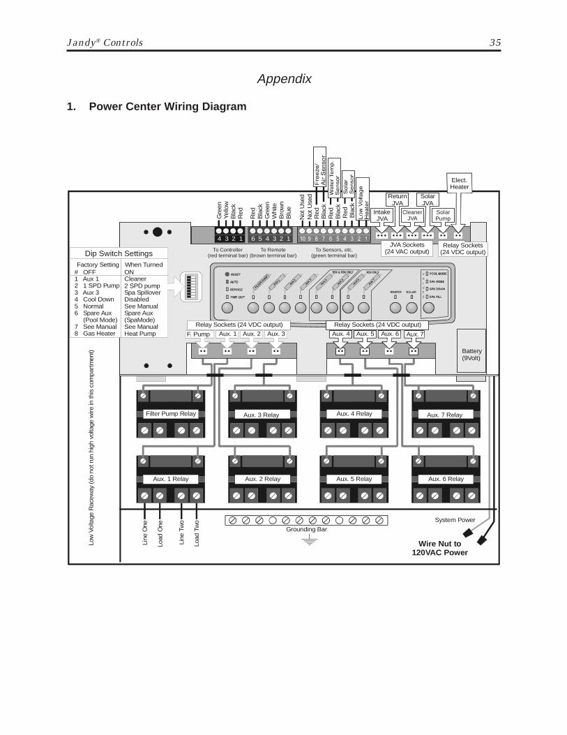
Appendix
1. Power Center Wiring Diagram
Aux. 4 Relay Aux. 7 Relay
Aux. 5 Relay Aux. 6 Relay
Filter Pump Relay Aux. 3 Relay
Aux. 1 Relay
Line
One
Low
Vol
tage
Rac
eway
(do
not
run
hig
h vo
ltage
wire
in th
is c
ompa
rtm
ent)
Line
Tw
o
Load
One
Load
Tw
o
Aux. 2 Relay
Grounding Bar
Wire Nut to 120VAC Power
System Power
IntakeJVA
CleanerJVA
SolarPump
ReturnJVA
SolarJVA
Elect.Heater
Red
Bla
ckG
reen
Whi
te
Yello
wG
reen
Bla
ckR
ed
Bro
wn
To Remote (brown terminal bar)
To Sensors, etc. (green terminal bar)
To Controller(red terminal bar)
4 3 2 1 6 5 4 3 2 1
Blu
e
Red
Bla
ckR
edB
lack
F. Pump Aux. 1 Aux. 2 Aux. 3 Aux. 6Aux. 5Aux. 4
Relay Sockets (24 VDC output)
JVA Sockets (24 VAC output)
# OFF1 Aux 12 1 SPD Pump3 Aux 34 Cool Down5 Normal6 Spare Aux (Pool Mode)7 See Manual8 Gas Heater
Battery(9Volt)
Dip Switch SettingsFactory Setting
ONCleaner2 SPD pumpSpa SpilloverDisabledSee ManualSpare Aux(SpaMode)See ManualHeat Pump
Red
Bla
ck
Not
Use
dN
ot U
sed
FILTER
PUMP
AUX 1AU
X 2
AUX 3
AUX 4
AUX 5
AUX 6
AUX 7
Relay Sockets (24 VDC output) Relay Sockets (24 VDC output)
When Turned

36 Jandy® AquaLink® RS
Appendix
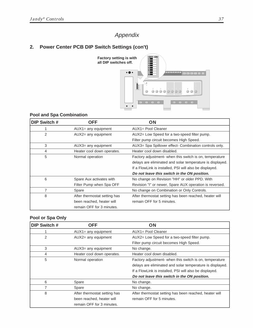
2. Power Center PCB DIP Switch Settings1. DIP #1 ON- AUX 1 Controls Pool Cleaner: If you installed a booster pump for a pool
cleaner, the relay coil for the booster pump must be plugged into the AUX 1 relay socket.If a non-booster pump cleaner is installed, plug the JVA into the cleaner JVA socket.Turn ON DIP Switch #1.• Main filter pump turns on whenever cleaner turns on.• Cleaner will not turn on until filter pump has been on for three (3) minutes (to ensure
priming of system).• Cleaner turns off when water circulation is to spa.• Cleaner turns off when spa spillover feature is activated.• Cleaner turns off for three (3) minutes when solar is activated (to ensure air is purged
from the system).• AquaLink RS Control Panel display reads "CLEANER" rather than "AUX 1".
2. DIP #2 ON- AUX 2 controls low speed of filter pump: Turn this switch ON if you want tocontrol both speeds of a two-speed filter pump. With this switch on, the filter pump button on theAquaLink RS Control Panel will control high speed and the AUX 2 button will control lowspeed. IMPORTANT: You must also install a Jandy Two-Speed Relay.
3. DIP #3 ON- AUX 3 controls spa spillover (operates with pool/spa combination):Turn this switch ON, and when the AUX 3 button on the AquaLink RS Control Panel (or SpaSide Switch) is pressed, the Return Valve Actuator will rotate to spa circulation. Because theIntake Valve Actuator does not rotate, the spa will fill with water and overflow into the pool.Note: leave AUX 3 relay socket empty.
4. DIP #4 ON- Heater cool down disabled: Turn this switch ON to disable the heater cool downsafety feature on the AquaLink RS. WARNING: Turn this DIP Switch ON only if you are usingan electric heater or a heat pump that does not retain residual heat. If you are turning this switchON for service purposes, be sure to turn it back off.
5. DIP #5 ON- Factory use only: This switch is used for calibration by Jandy certified techniciansonly (will momentarily display the solar temperature). If a FlowLink is installed, this will displaywater pressure. Please leave this switch in the off position.
6. DIP #6 ON- Change Spare AUX to activate when Filter Pump is on and system is in spa mode(pool/spa combination units only). Spare AUX socket is on the back side of the Power CenterPCB.
7. DIP #7 ON- Not used
8. DIP #8 ON- Heat pump instead of gas heater: Turn this switch ON if you have installed a heatpump instead of a gas heater.
Jandy® Controls 37
1OFF ON
345678
2Factory setting is withall DIP switches off.
Appendix
2. Power Center PCB DIP Switch Settings (con't)
Pool and Spa Combination
DIP Switch # OFF ON1 AUX1= any equipment AUX1= Pool Cleaner
2 AUX2= any equipment AUX2= Low Speed for a two-speed filter pump.
Filter pump circuit becomes High Speed.
3 AUX3= any equipment AUX3= Spa Spillover effect- Combination controls only.
4 Heater cool down operates. Heater cool down disabled.
5 Normal operation Factory adjustment- when this switch is on, temperature
delays are eliminated and solar temperature is displayed.
If a FlowLink is installed, PSI will also be displayed.
Do not leave this switch in the ON position.6 Spare Aux activates with No change on Revision "HH" or older PPD. With
Filter Pump when Spa OFF Revision "I" or newer, Spare AUX operation is reversed.
7 Spare No change on Combination or Only Controls.
8 After thermostat setting has After thermostat setting has been reached, heater will
been reached, heater will remain OFF for 5 minutes.
remain OFF for 3 minutes.
Pool or Spa Only
DIP Switch # OFF ON1 AUX1= any equipment AUX1= Pool Cleaner
2 AUX2= any equipment AUX2= Low Speed for a two-speed filter pump.
Filter pump circuit becomes High Speed.
3 AUX3= any equipment No change.
4 Heater cool down operates. Heater cool down disabled.
5 Normal operation Factory adjustment- when this switch is on, temperature
delays are eliminated and solar temperature is displayed.
If a FlowLink is installed, PSI will also be displayed.
Do not leave this switch in the ON position.6 Spare No change.
7 Spare No change.
8 After thermostat setting has After thermostat setting has been reached, heater will
been reached, heater will remain OFF for 5 minutes.
remain OFF for 3 minutes.
38 Jandy® AquaLink® RS
Appendix
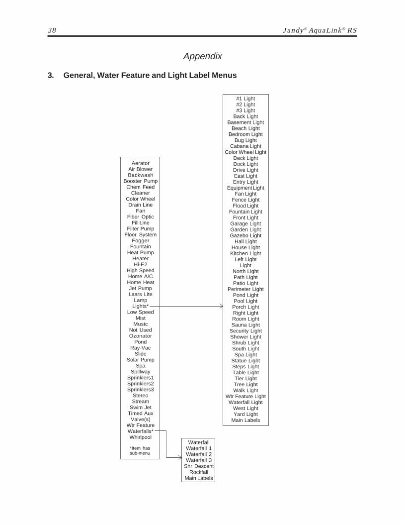
3. General, Water Feature and Light Label Menus
AeratorAir BlowerBackwash
Booster PumpChem Feed
CleanerColor WheelDrain Line
FanFiber Optic
Fill LineFilter Pump
Floor SystemFogger
FountainHeat Pump
HeaterHi-E2
High SpeedHome A/CHome HeatJet PumpLaars Lite
LampLights*
Low SpeedMist
MusicNot UsedOzonator
PondRay-Vac
SlideSolar Pump
SpaSpillway
Sprinklers1Sprinklers2Sprinklers3
StereoStream
Swim JetTimed AuxValve(s)
Wtr FeatureWaterfalls*Whirlpool
*Item hassub-menu
#1 Light#2 Light#3 Light
Back LightBasement Light
Beach LightBedroom Light
Bug LightCabana Light
Color Wheel LightDeck LightDock LightDrive LightEast LightEntry Light
Equipment LightFan Light
Fence LightFlood Light
Fountain LightFront Light
Garage LightGarden LightGazebo Light
Hall LightHouse LightKitchen Light
Left LightLight
North LightPath LightPatio Light
Perimeter LightPond LightPool Light
Porch LightRight LightRoom LightSauna Light
Security LightShower LightShrub LightSouth LightSpa Light
Statue LightSteps LightTable LightTier LightTree LightWalk Light
Wtr Feature LightWaterfall Light
West LightYard Light
Main Labels
WaterfallWaterfall 1Waterfall 2Waterfall 3
Shr DescentRockfall
Main Labels

6000 Condor Drive, Moorpark, CA, USA 93021 • 707.776.8200 FAX 707.763.7785480 S. Service Road West, Oakville, Ontario, Canada L6K 2H4 • 905.844.8233 FAX 905.844.2635
Litho in U.S.A. © Water Pik Technologies, Inc. 0307
Sheet # 6594 Rev. F For Technical Support call 707-776-8200, ext. 260
EXCLUSIONS: The liability of Laars and Jandy shall not exceed the repair or replacement of defective parts and does not include any costs for labor to remove and reinstall the defective part, transportation to or from the factory, and any other materials required to make the repair.
This warranty does not cover failures or malfunctions resulting from the following:
1. Failure to properly install, operate or maintain the product(s) in accordance with our published Installation, Op er a tion and Maintenance Manuals provided with the product(s); 2. The workmanship of any installer of the product(s); 3. Not maintaining a proper chemical balance [pH level between 7.2 and 7.8, Total Alkalinity (TA) between 80 to 120 ppm, Total Dissolved Solids (TDS) less than 2000]; 4. Abuse, alteration, accident, fi re, fl ood, lightning, rodents, insects, negligence or acts of God; 5. Scaling, freezing, or other conditions causing inadequate water circulation; 6. Operating the product(s) at water fl ow rates outside the published minimum and maximum specifi cations; 7. Use of non-factory authorized parts or accessories in conjunction with the product(s); 8. Chemical con tam i na tion of combustion air or improper use of sanitizing chemicals such as, introducing sanitizing chemicals upstream of the heater and cleaner hose or through the skimmer; 9. Over heat ing, incorrect wire runs, improper electrical supply, collateral damage caused by failure of O-Rings, DE grids, or cartridge elements, damage caused by running the pump with insuffi cient water; 10. The installation of a surge protection kit does not extend the warranty of the original product(s).
LIMITATION OF LIABILITY: This is the only warranty given by Laars and Jandy. No one is authorized to make any other warranties on Laars and Jandy be-half. THIS WAR RAN TY IS IN LIEU OF ALL OTHER WARRANTIES, EXPRESS OR IMPLIED, IN CLUD ING BUT NOT LIM IT ED TO ANY IMPLIED WAR RAN TIES OF FITNESS FOR A PARTICULAR PURPOSE AND MER CHANT ABIL I TY. LAARS AND JANDY EXPRESSLY DISCLAIMS AND EX CLUDES ANY LI A BIL I TY FOR CON SE QUEN TIAL, IN CI DEN TAL, IN DI RECT OR PU NI TIVE DAMAGES FOR BREACH OF ANY EX PRESS OR IMPLIED WAR RAN TY. This warranty gives you specifi c legal rights, and you may also have other rights which vary from state to state or by province.
WARRANTY CLAIMS: For prompt warranty consideration, contact your dealer and provide the following information: proof of purchase, model number, serial number and date of installation. The installer will notify the factory for instructions regarding the claim and for the location of the nearest Laars and Jandy des ig -nat ed service center. If the dealer is not available, you can locate a service center in your area by visiting www.jandy.com or you can call the Technical Support De part ment at (707) 776-8200 ext. 260 for as sis tance. All returned parts must have a Returned Material Au tho ri za tion number in order to be con sid ered for war-ranty eval u a tion. If there are any ques tions about the coverage of this warranty, please contact Laars and Jandy at the address below.
LIMITED WARRANTYThese warranties extend only to the fi rst retail purchaser of Laars and Jandy products that have not been moved from their original installation sites. Laars and Jandy warrants all parts to be free from manufacturing defects in ma te ri al and work man ship as detailed below for the designated time frame, commencing from the date of in stal la tion. If any parts are found to have manufacturing defects, Laars and Jandy will provide re place ment of such de fec tive parts.
1 year 2 years 3 years 5 years LifetimeCleaners:Ray-Vac® X Others XControl Systems:AquaLink® RS and Accessories XAquaLink® RS (w/Surge Protection) X X($50 Deductible) X($75 Deductible) AquaSwitch®, Pool Control, Ji, and Solar Control XFilters: X TankHeaters:Lite2 Controls, Firebox Panels, All Other Parts Heat Exchanger, BurnersLX, Hi-E2 Controls, Firebox Panels, All Other Parts Heat Exchanger, Fan Motor, Burners Hot Shot XOil-Fired, XL-2, XL-3 Oil Burner, Controls All Other Parts Heat Exchanger, Firebox Pumps: X Motor (from Manufacturer)Jandy Valve Actuator: X Valves:NeverLube® XOthers XWater Features: X