all about ac motors - plc-doc
TRANSCRIPT
All about AC Motors This part of document only provides brief definitions of the key terms and concepts that is just a part of the complete document. You may download the complete document from website just by clicking on:
Symbol to download the PDF file.
Two-phase induction motors Although the 3-phase induction motor is more efficient, some two-phase power motors are used. Also, the two-phase motor is used in many servo applications because transistor circuits can be used to control its speed and direction of rotation. Figure 19(A) shows the schematic diagram used to represent a two-phase ac motor. Each phase has a separate winding displaced 90° from the other phase winding. The rotor is squirrel-cage type just like that used in the 3-phase motor. Figure 19(B) shows the stator of two-pole, two-phase induction motor. Poles 1 and 3 are energized by phase A and poles 2 and 4 are energized by phase B. phase A and B of the supply voltage are 90° out of phase as shown in the voltage waveforms of figure 19(C). This two-phase supply sets up a magnetic field in the poles of the stator. The magnetic fields combine to form a single resultant magnetic field. The strength and direction of the magnetic fields change in sequence to cause the resultant magnetic field to rotate. Just as in the 3-phase motor, the resultant magnetic field has a constant strength and rotates one complete revolution for one cycle of the ac supply voltage. This makes the synchronous speed 3600 rpm for a two-pole stator. The synchronous speed formula applies to the 2-phase motor the same as the 3-phase motor. Like the 3-phase motor, the 2-phase motor can be made with more poles per phase to decrease the synchronous speed. In figure 19(C), phase a leads phase B by 90° causing the rotating field to turn clockwise. If either phase A or phase B is shifted 180°, phase B will lead phase A by 90° and the rotating field will turn counterclockwise. Therefore, if we want to reverse the direction of rotation of any 2-phase motor, we can simply reverse the supply leads to one phase. The discussion on slip and torque given with the 3-phase motor applies equally well to the 2-phase motor.
1
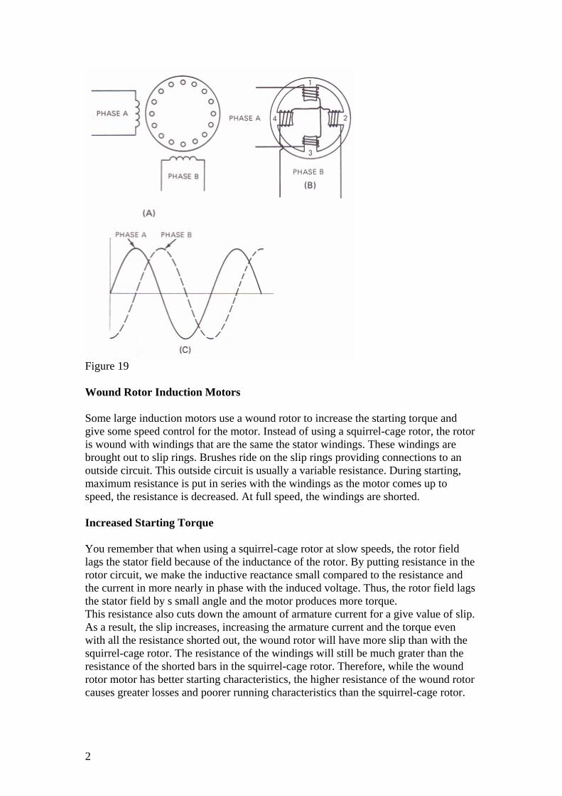
Figure 19 Wound Rotor Induction Motors Some large induction motors use a wound rotor to increase the starting torque and give some speed control for the motor. Instead of using a squirrel-cage rotor, the rotor is wound with windings that are the same the stator windings. These windings are brought out to slip rings. Brushes ride on the slip rings providing connections to an outside circuit. This outside circuit is usually a variable resistance. During starting, maximum resistance is put in series with the windings as the motor comes up to speed, the resistance is decreased. At full speed, the windings are shorted. Increased Starting Torque You remember that when using a squirrel-cage rotor at slow speeds, the rotor field lags the stator field because of the inductance of the rotor. By putting resistance in the rotor circuit, we make the inductive reactance small compared to the resistance and the current in more nearly in phase with the induced voltage. Thus, the rotor field lags the stator field by s small angle and the motor produces more torque. This resistance also cuts down the amount of armature current for a give value of slip. As a result, the slip increases, increasing the armature current and the torque even with all the resistance shorted out, the wound rotor will have more slip than with the squirrel-cage rotor. The resistance of the windings will still be much grater than the resistance of the shorted bars in the squirrel-cage rotor. Therefore, while the wound rotor motor has better starting characteristics, the higher resistance of the wound rotor causes greater losses and poorer running characteristics than the squirrel-cage rotor.
2

Speed Adjustment The speed of the wound rotor induction motor can be adjusted over a small range by adjusting the value of resistance in series with the rotor windings. The added resistance limits the rotor current causing the rotor slip to increase and the motor to run at a slower speed. Wound rotors are more expensive to build than squirrel-cage rotors. Therefore, wound rotor induction motors are used only where a large starting torque is needed or where some speed adjustment is required, making the increased cost of the wound rotor worthwhile. 3-phase synchronous motors A synchronous motor is an ac motor in which the rotor turns at the synchronous speed of the rotating field. The speed of the motor is locked to the frequency of the ac supply. Synchronous motors are used where constant motor speed is important. These motors are made in sizes ranging from 5000 hp or more down to one-millionth of a horsepower. The large power synchronous motors use 3-phase stator windings like 3-phase induction motors. The stator of the 3-phase synchronous motor is exactly like the stator of the 3-phase induction motor we studied earlier in this lesson. Like the induction motor, this 3-phae winding sets up a rotating magnetic field. The difference between 3-phase induction motor and a 3-phase synchronous motor is in the rotor. Instead of the squirrel-cage rotor, the synchronous motor uses a dc electromagnet for the rotor. This electromagnet lock to the rotating magnetic field and the rotor turns at the synchronous speed wit no slip.
DC-excited rotor
Direct-Current Field Excitation
In the early models, the field circuits excited from an external direct-current source. A dc generator may be coupled to the motor shaft to supply the dc excitation current.
Figure 20 shows the connections for a synchronous motor. A field rheostat in the separately excited field circuit varies the current in the field circuit. Changes in the field current affect the strength of the magnetic field developed by the revolving rotor. Variations in the rotor field strength don't affect the motor which continues to operate at a constant speed. However, changes in the dc field excitation do change the power factor of a synchronous motor.
3

Figure 20 Brushless Solid-State Excitation An improvement in synchronous motor excitation is the development of the brushless dc exciter. The commutator of a conventional direct-connected exciter is replaced with a three-phase, bridge-type, solid-state rectifier. The dc output is then fed directly to the motor field winding. Simplified circuitry is illustrated in figure 21. A stationary field ring for the ac exciter receives dc from a small rectifier in the motor control cabinet. This rectifier is powered from the ac source. The exciter dc field is also adjustable. Rectifier solid-state diodes change the exciter ac output to dc. This dc is the source of excitation for the rotor field poles. Silicon-controlled rectifiers, activated by the solid-state field control circuit, replace electromechanical relays and the contactors of the conventional brush-type synchronous motor.
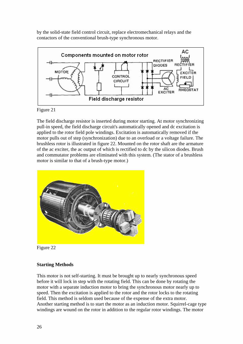
Figure 21 The field discharge resistor is inserted during motor starting. At motor synchronizing pull-in speed, the field discharge circuit's automatically opened and dc excitation is applied to the rotor field pole windings. Excitation is automatically removed if the motor pulls out of step (synchronization) due to an overload or a voltage failure. The brushless rotor is illustrated in figure 22. Mounted on the rotor shaft are the armature of the ac exciter, the ac output of which is rectified to dc by the silicon diodes. Brush and commutator problems are eliminated with this system. (The stator of a brushless motor is similar to that of a brush-type motor.)
4

Figure 22 Starting Methods This motor is not self-starting. It must be brought up to nearly synchronous speed before it will lock in step with the rotating field. This can be done by rotating the motor with a separate induction motor to bring the synchronous motor nearly up to speed. Then the excitation is applied to the rotor and the rotor locks to the rotating field. This method is seldom used because of the expense of the extra motor. Another starting method is to start the motor as an induction motor. Squirrel-cage type windings are wound on the rotor in addition to the regular rotor windings. The motor comes up to nearly synchronous speed as an induction motor. Then the dc excitation voltage is applied to the regular rotor windings and the rotor locks to the rotating field, turning the rotor at the synchronous speed. These motors may not produce enough starting torque t get the motor near synchronous speed when starting under load. In this case, you may find a clutch between the motor and the load. The motor is started with the clutch disengaged. When the motor is up to synchronous speed, the clutch is slowly engaged, bringing the load up to synchronous speed. Special rotor windings can be used to give the motor a high starting torque and bring the rotor up to synchronous speed. These rotors are expensive and are used only where the motor must be coupled directly to a heavy load. The rotor has high-resistance squirrel-cage type windings to give the higher starting torque. The regular electromagnet windings are made of heavier wire and are excited by a lower dc voltage. Constant speed
Synchronous speed = (120 × frequency) / number of poles
S = (120×f) / p
Figure 23 shows the speed-torque curve for a typical synchronous motor. The dotted line shows the motor coming up to speed as an induction motor. When the dc excitation is applied, the rotor suddenly pulls into step with the rotating field. The
5

speed-torque curve becomes a straight line at 100 percent synchronous speed. The motor maintains this constant speed from no load to over 150 percent of full-load torque.
Figure 23 Power Factor The amount of dc excitation used controls the power factor of the motor. If the excitation is weak, some of the magnetizing voltage for the rotor is taken from the ac supply. This causes a lagging power factor like an ordinary induction motor. If the excitation is increased above that needed for magnetizing the rotor core, the rotor is said to be overexcited. This causes a leading power factor. This feature is taken advantage of only in very large installations where it is desirable to correct the power factor as close to unity as possible.
These tags are related to the topics will be discussed in the PDF file are: AC motors, single-phase motors, rotor, stator, stator windings, rotor windings , secondary windings of a transformer, slip rings , stator , Squirrel-cage Rotor, copper shorting rings, windings, Rotor of an induction motor, Rotating field, 3-phase motor field, rotating magnetic field , two -pole, 3-phase stator , Two-pole , phase, 3-phase supply voltage, Induced Voltage, 3-phase supply is applied to the stator, changing the direction of rotation, clockwise, clockwise rotation ,Synchronous Speed, supply frequency ,N = synchronous speed in rpm, f = frequency of applied voltage in Hz, P = number of poles per phase, the synchronous speed , slip and Torque, increase the slip , torque, Locked rotor torque, starting-current ,full load current, overcurrent protection devices, AC motors de-rating factors, AC motors and Drives, adjustable speed drives (ASD) , adjustable frequency drives (AFD), variable frequency drives (VFD) , variable speed drives (VSD) , frequency converters (FC),fixed speed , fixed torque, (variable speed) AC drive, 3-phase motor voltage , Torque= force × radius, Mounting Positions of AC motors, Two-phase induction motors, two-phase power motors, squirrel-cage, two-phase supply, synchronous speed formula applies to the 2-phase motor the same as the 3-phase motor, 3-phase motor applies equally well to the 2-phase motor, Wound Rotor Induction Motors, Increased Starting Torque, squirrel-
6

cage rotor at slow speeds, squirrel-cage rotor, Speed Adjustment, 3-phase synchronous motors, Excitation ,synchronization, overload or a voltage failure, brushless rotor, brush-type motor, starting Methods, Squirrel-cage windings , rotor windings, excitation voltage , Synchronous speed = (120 × frequency) / number of poles , full-load torque, Power Factor, Single-phase Motors, shaded pole motor, the split phase motor, the permanent split capacitor motor (also called the single value capacitor motor), and Capacitor start/capacitor run, permanent split capacitor (PSC) , two value capacitor motors , split phase and the two value capacitor motors , centrifugal switch, PSC motors don’t have a switch, Split phase motors , PSC motors ,higher starting torque and higher efficiency than motors with no capacitor, AC single-phase induction motor, shaded-pole motor, squirrel-cage motor , shaded pole, 2-phase rotating magnetic field, Shaded-pole motors , TRIAC-based variable-speed controls, Split phase motor, split-phase motor , permanent split capacitor motor (PSC), Capacitor start/capacitor run, capacitor-start/induction-run motor , permanent split capacitor motor, breakdown or overload torque, capacitor-start/capacitor-run motor, lower full-load currents , horsepower, powerhouse, high-pressure water pumps, vacuum pumps ,
7

WNcc5dqKeHD/be.youtu://http
All about AC motors ADfFPOzIUE0/be.youtu://http
oqLRxXcHk51/be.youtu://http
Introduction
8 oCeo1z4mJfT/be.youtu://http

Welcome to another course offered from educational department of plcgoods.net. These technical educational programs are designed to educate those who come to checkout tutorial materials related to single base computers or PLCs. This course shall cover All about AC motors and some related components or products.
Table of content 3-phase induction motors, Squirrel-cage rotor...................................................... 10 Rotating field ........................................................................................................ 11 Induced voltage, conclusion.................................................................................. 14 Direction of rotation, synchronous speed ............................................................. 15 Slip and torque ...................................................................................................... 16 Locked rotor torque, Breakdown torque, full-load torque.................................... 18 Starting and full-load current ................................................................................ 18 AC motors de-rating factors.................................................................................. 19 AC motors and Drives, calculating torque............................................................ 20 Mounting positions of AC motors, mounting faces.............................................. 22 Two-phase induction motors................................................................................. 23 Wound rotor induction motors, increased starting torque .................................... 24 DC-excited rotor, Direct-Current field excitation ................................................ 25 Starting methods ................................................................................................... 26 Split phase motor ................................................................................................. 30 The permanent split capacitor motor (PSC).......................................................... 31 Capacitor start/capacitor run ................................................................................. 32
9

3-phase induction Motors An electric motor is a machine that converts electrical energy into mechanical energy. The flow of current through a system of conductors placed in a magnetic field is converter into a motion of these conductors about a shaft. Mechanical power is thus made available at the shaft. The type and size of motor used for a particular job depends on the load. Some jobs, such as the operation of an elevator, require that the motor start under heavy load. Other jobs need a motor that will maintain a constant speed, such as the motor in an electric clock. Still other applications require that the motor be controlled by electronic circuitry. In such cases, the control circuits are designed to match the characteristics of the motor. There are many types of AC motors, but this course focuses on 3-phase AC induction motors, the most common type of motor used in industrial applications. Most large AC power motors are polyphase motors because they are more efficient than single-phase motors. Also, polyphase induction motors are simply constructed and require little maintenance. Induction motors get their name from the fact that the current in the rotor is induced from the stator. The stator windings are connected to the supply line and act like the primary of a transformer. The rotor windings act like the secondary windings of a transformer. When current flows in the stator windings, a voltage is induced in the rotor windings, causing current to flow. The rotor has neither slip rings nor commutator, so it has no direct electrical connection to the supply. Next figure shows (A) stator and (B) rotor of a typical three-phase ac induction motor.
Figure 1: As you see from the picture, the frame supports the stator core, which is made of laminated steel to cut down on losses. The stator windings are embedded in slots in the stator core. Squirrel-cage Rotor The rotor core is also made of laminated steel. Heavy copper bar conductors are embedded in slots on the rotor core. The ends of the bars are welded to copper shorting rings. Next shows the construction of the rotor without the steel core. This is called a squirrel-cage rotor because of its appearance. These bars And shorting rings form short-circuited windings. The voltage in the stator induces a voltage in these windings, which causes large currents flow in these shorted windings.
10

Fig. 2: Rotor of an induction motor without the steel laminations. Rotating field The 3-phase motor voltage supplied to the stator of an induction motor sets up a rotating magnetic field. To see how this rotating magnetic field is produced, look at the next figure which shows the winding connections of the stator. Notice how each phase produces a magnetic field. These three magnetic fields combine to form a single resultant magnetic field. We sill relate the current in the stator windings to the magnetic fields to see how the resultant magnetic field rotates. Figure A shows a delta-connected, two-pole, 3-phase stator connected to a 3-phase AC supply. Two-pole refers to the fact that there are two poles for each phase. The windings for poles 1 and 4 are connected to phase A. Likewise, poles 3 and 6 are supplied by phase B and poles 2 and 5 are supplied by phase C. These pairs of poles are wound so that when one pole is N, the other pole of that pair is S.
Fig.3 Next figure shows a plot of the 3-phase supply voltage. Each phase is displaced 120° from the other two phases. As these voltages rise and fall, they cause currents to flow
11

in the stator windings. These currents set up the magnetic fields. In discussing the action of these fields, we will relate the current in the windings to the magnetic field. The windings of a motor are highly inductive so the current lags the applied voltage by a large angle. The fields produced are in phase with the current through the windings.
Fig.4 The magnetic field of an electromagnet has the same characteristics as a natural magnet, including a north and south pole. However, when the direction of current flow through the electromagnet changes, the polarity of the electromagnet changes. The polarity of an electromagnet connected to an AC source changes at the frequency of the AC source. This is demonstrated in the following illustration. At time 1, there is no current flow, and no magnetic field is produced. At time 2, current is flowing in a positive direction, and a magnetic filed builds up around the electromagnet. Note that the South Pole is on the top and the North Pole is on the bottom. At time 3, current flow is at its peak positive value, and the strength of the electromagnetic field has also peaked. At time 4, current flow decreases, and the magnetic field begins to collapse. At time 5, no current is flowing and no magnetic field is produced. At time 6, current is increasing in the negative direction. Note that the polarity of the electromagnetic field has changed. The North Pole is now on the top, and the South Pole is on the bottom. The negative half of the cycle continues through times 7 and 8, returning to zero at time 9. for a 60 HZ AC power supply, this process repeats 60 times a second. Induced Voltage In the previous examples, the coil was directly connected to a power supple. However, a voltage can be induced across a conductor by merely moving it though a magnetic field. This same effect is caused when a stationary conductor encounters a changing magnetic field. This electrical principle is critical to the operation of AC induction motors.
12

Fig.5: This picture illustrates that the polarity of an electromagnet connected to an AC source changes at the frequency of the AC source. In the following illustration, an electromagnet is connected to an AC power source. Another electromagnet is placed above it. The second electromagnet is in a separate circuit and there is no physical connection between the two circuits. This illustration shows the build up of magnetic flux during the first quarter of the AC waveform. At time 1, voltage and current are zero in both circuits. At time 2, voltage and current are increasing in the bottom circuit. As magnetic field builds up in the bottom electromagnet, lines of flux from its magnetic field cut across the top electromagnet and induce a voltage across the electromagnet. This causes current to flow through the ammeter. At time 3, current flow has reached its peak in both circuits. As in the previous example, the magnetic field around each coil expands and collapses in each half cycle, and reverses polarity from one half cycle to another.
13

Fig. 6: To see why the magnetic field will rotate when the 3-phase supply is applied to the stator, we must examine the magnetic fields at different times in the cycle. Next figure shows how the rotating field is produced in the 3-phase stator. figure shows the current waveform IA, of the current flow through windings 1 and 4 for one cycle. The small illustrations below the current waveform show the magnitude and polarity of the field set up by poles 1 and 4 at different times in the current cycle. Figure (B) shows the same relationship for phase B consisting of coils 3 and 6. this current waveform IB lags IA by 120 °. Figure (C) shows current IC for phase C lags IB 120° and sets up fields in poles 2 and 5. Figure (D) combines the vectors representing the field strength and direction for the 3-phases. The heavy black arrow represents the resultant magnetic field. The strength of this resultant magnetic field remains the same as it rotates. Conclusion By examining the currents and fields through one complete cycle, you can see that the resultant magnetic field remains the same strength and rotates one complete revolution for one cycle of the applied voltage. In this way, the strength and direction of the fields of the individual phases change in sequence to produce one rotating magnetic field. Now let's see how this rotating magnetic field can make a squirrel-cage rotor turn. We saw in the previous picture that the squirrel-cage rotor has many shorted conductors. When this rotor is placed in the rotating field set up by the stator, the lines of flux of the rotating field cut the shorted conductors. This induces a voltage in the conductors, causing a large current to flow in the shorted conductors. This large current sets up a magnetic field in the rotor, which is the opposite polarity of the field in the stator. Consequently, an S pole is induced in the end of the rotor, which is opposite the N pole in the stator field. As the field of the stator rotates, it attracts the field in the rotor and the rotor turns in the same direction as the rotating magnetic field.
14

The rotor does not turn as fast as the rotating field. When the rotor is not turning, the field cuts the conductors at the maximum rate and induces the maximum voltage in the rotor. As the rotor turns and follows the rotating field, less voltage is induced because the field cuts the conductors at a slower rate. If the rotor turned at the same speed as the rotating field, there would be no voltage induced in the rotor conductors. With no voltage induced in the rotor, the rotor would not have a magnetic field. We know that the torque produced by a motor is proportional to the strength of the two fields that are interacting to cause rotation. With no current in the rotor, there would be no field in the rotor and no turning force. Therefore, the rotor would slow down. As the rotor slows down, the lines of the field cut the conductors of the rotor and cause the rotor to produce a field. The rotor field interacts with the stator field to produce the turning force. Direction of Rotation Because the rotor turns in the same direction as the rotating magnetic field, the direction of rotation of the motor can be reversed by changing the direction of rotation of the rotating field. The direction of rotation of the rotating field depends upon the phase relationship of the currents in the stators windings. In the previous figure, IB lags IA by 120° and IC lags IB by 120°. This causes the rotating field to turn clockwise. Interchanging any two of the supply leads will change the phase relationship of two of these phases and cause the rotating field to rotate in the opposite direction. Next figure shows how reversing the phase terminals of a 3-phase motor will change the direction of rotation.
Fig. 7: The connections are shown for clockwise rotation at 1. By interchanging connections C and B as at 2, the motor turns counterclockwise as shown by the arrow. Interchanging connections A and B as shown in 3 will cause the motor again to turn clockwise. Thus, anytime you want to reverse the direction of rotation of a 3-phase motor, just reverse any two leads. Synchronous Speed
The synchronous speed of an induction motor is based on the supply frequency and the number of poles in the motor winding and can be expressed as:
15

Where
N = synchronous speed in rpm
f = frequency of applied voltage in Hz
P = number of poles per phase
In a two pole machine using a 60 Hz supply, the synchronous speed is:
N = (60 × 120) ÷ 2 = 3600 rpm
In an ac motor with four poles per phase and a 60 Hz supply, the synchronous speed is:
N = (60 × 120) ÷ 4 = 1800 rpm
Slip and Torque
You have learned that the rotor of an induction motor turns slower than the rotating field. This allows the lines of flux of the field to cut the conductors of the rotor and induce a voltage in the rotor. The difference between the synchronous speed and the speed of the rotor is called slip. With more slip, more current will flow in the rotor and the motor will develop more torque. Also, as the slip increases, the speed of the motor decreases.
Thus, motor speed is equal to the synchronous speed minus the slip. Slip in expressed in percentage of the synchronous speed. For example, a motor with a full-load of 1750 rpm and a synchronous speed of 1800 has a slip of 50 rpm.
= 2.78 %
A heavier load on the motor will increase the slip and the torque. Induction motors have good torque at near synchronous speeds. Following figure shows the speed-torque curve for a typical 3-phase induction motor. The percentage of full-load torque is plotted against the percentage of synchronous speed. At no load, the torque is nearly zero and the motor runs at nearly its synchronous speed. As the load increased, the speed falls off slightly. At full load (100 percent full-load torque), the slip is about 4 percent and the motor runs at 96% percent of its synchronous speed. With the load
16

increased to 200 percent of full load torque, the speed is still nearly 90 percent of the synchronous speed.
Speed-Torque curve for NEMA B motor
Fig.8 Because motor torque varies with speed, the relationship between speed and torque is often shown in a graph, called a speed-torque curve. This curve shows the motor's torque, as a percentage of full-load torque, over the motor's full speed range, shown as a percentage of its synchronous speed. The above speed-torque curve is for a NEMA B motor. NEMA B motors are general purpose, single speed motors suited for applications that require normal starting and running torque, such as pumps, lightly-loaded conveyors, and machine tools. Using a 30 HP, 1765 RPM NEMA B motor as an example, full-load torque can be calculated by transposing the formula for horsepower.
Torque (in lb-ft) = (HP × 5252) ÷ (Speed (in RPM)) = (30 × 5252) / 1765 = 89.3 lb-ft
17

Locked rotor torque Starting torque or locked rotor torque is the torque that the motor develops each time it is started at rated voltage and frequency. So the definition of Lock rotor torque is The torque that a motor produces when full power is supplied to the motor and the rotor is not yet moving. Pull-up Torque
Pull-up torque - such a value of torque which allows an electric motor to accelerate the load to the normal operating conditions. In other words: a maximum load which can be accelerated to the nominal conditions. This is the lowest point on the torque curve and for asynchronous motors can be synonymous with starting torque.
Fig. 9 Breakdown Torque Breakdown torque is the greatest amount of torque a motor can attain without stalling. High breakdown torque is necessary for applications that may undergo frequent overloading. One such application is a conveyor belt. Often, conveyor belts have more product placed upon them than their rating allows. High breakdown torque enables the conveyor to continue operating under these conditions without causing heat damage to the motor. Full-Load Torque Full load torque is produced by a motor functioning at a rated speed and horsepower. The operating life is significantly diminished in motors continually run at levels exceeding full load torque. Also, refer to figure 10. Starting and full-Load Current Starting-current (also called inrush) is the current drawn by a motor during its runup, or acceleration, to normal operating speed. Its value is in Amperes. Typically it can be from 4 to 8 times the rated current. Ignoring the transients of the first 2 or 3 cycles,
18

then starting-current lasts from the time the motor is first energized (breakaway) until the motor nears full speed... often defined as starting-time. The "full load current" is the current taken by a motor when it is delivering its full rated output power. Now, how is the "full load current" different to the "starting current"- is the "full load current" higher or lower than the starting current? And what about the lengths of time that a motor can safely run on "starting" and "full load" currents? And how do these currents affect the temperature of the motor casing, its windings and its surroundings?
Figure 10 For a NEMA B motor, starting current is typically 600-650% of full-load current knowledge of the current requirements for a motor is critical for the proper application of overcurrent protection devices. AC motors de-rating factors
Temperature rise for NEMA rated motors is based on operation at altitudes of 3,300 feet or less, with a maximum ambient temperature of 104 Degrees F. Altitudes up to and including 3,300 feet are considered the equivalent of sea level. One typical characteristic of high altitude locations is low air density. Low density air does not allow a motor to cool as well as the air at sea-level. However, the decrease in ambient temperature characteristic of high altitudes generally compensates for the increase in temperature rise due to low air density.
Motors with Class B or F insulation systems operate satisfactorily at altitudes above 3,300 feet if the ambient temperature is lower than 104 Degrees F. This table shows how lower ambient at high altitude make up for lower air density.
Figure11
19

AC motors and Drives An AC drive is a device that is used to control the speed of an electrical motor, either an induction motor or a synchronous motor. AC drives are also known by various other names such as adjustable speed drives (ASD) or adjustable frequency drives (AFD), variable frequency drives (VFD) or variable speed drives (VSD) or frequency converters (FC). Electrical motors convert electric energy into mechanical energy by electromagnetic induction. These motors are characterized by: 1- fixed speed (determine by the frequency of the power supply) 2- fixed torque. If speed control is required, that controller is called a (variable speed) AC drive. AC drives are used in a wide variety of industrial applications. However, variable speed AC drives are commonly used in more complex environments such as water and wastewater processing, paper mills, tunnel boring, oil drilling platforms or mining. The speed is controlled by changing the frequency of the electrical supply to the motor. The 3-phase motor voltage in the national electrical grid connected to a motor creates a rotating magnetic field in it. The rotor of the electrical motor will follow this rotating magnetic filed. An AC drive converts the frequency of the network to anything between 0 to 300 HZ or even higher, and thus controls the speed of motor proportionally to the frequency. Fig.12 illustrates photo of some typical adjustable frequency drives offer the greatest selection of size and performance available, with power ranges from fractional HP to 1750 HP.
Figure 12 Calculating load torque The following illustration shows a pulley fastened to the shaft of a load. A cord is wrapped around the pulley with one end connected to a spring scale. Pull on the scale until the shaft turns and note the force reading on the scale. Then, just multiply the force required to turn the shaft by the radius of the pulley to calculate the torque value. See figure 13.
20

Torque= force × radius Load torque is the minimum amount of force that a motor would have to apply to a system with a known load. For example, a crane with a 2-foot diameter cable drum holding a 1,000-pound weight aloft would have to apply a force of at least 1,000-foot-pounds of torque to the drum shaft just to hold the weight in place. However, this force could be supplied by a motor with a much lower torque rating if the right load torque multiplication calculation is performed Torque = 1000 × 1 = 1000-foot- pounds Mounting Positions of AC motors The typical floor mounting positions are illustrated in the following drawing, and are referred to as F-1 and F-2 mountings.
Figure 14 Type wall and ceiling mounts are shown in the following illustration. Wall mounting positions have the prefix W and ceiling mounted positions have the prefix C.
21

Figure 15 Mounting Faces It is sometimes necessary to connect the motor directly to the equipment it drives. In the following example a motor is connected directly to a gear box.
Figure 16 The C-face, or the end, of a C-face motor has threaded bolt holes. Bolts to mount the motor pass through mating holes in the equipment and into the face of the motor.
Figure 17 D-flange The bolts go through the holes in the flange of a D-flange motor and into threaded mating holes of the equipment. See figure 18.
Figure 18
22

Two-phase induction motors Although the 3-phase induction motor is more efficient, some two-phase power motors are used. Also, the two-phase motor is used in many servo applications because transistor circuits can be used to control its speed and direction of rotation. Figure 19(A) shows the schematic diagram used to represent a two-phase ac motor. Each phase has a separate winding displaced 90° from the other phase winding. The rotor is squirrel-cage type just like that used in the 3-phase motor. Figure 19(B) shows the stator of two-pole, two-phase induction motor. Poles 1 and 3 are energized by phase A and poles 2 and 4 are energized by phase B. phase A and B of the supply voltage are 90° out of phase as shown in the voltage waveforms of figure 19(C).
Figure 19 This two-phase supply sets up a magnetic field in the poles of the stator. The magnetic fields combine to form a single resultant magnetic field. The strength and direction of the magnetic fields change in sequence to cause the resultant magnetic field to rotate. Just as in the 3-phase motor, the resultant magnetic field has a constant strength and rotates one complete revolution for one cycle of the ac supply voltage. This makes the synchronous speed 3600 rpm for a two-pole stator. The synchronous speed formula applies to the 2-phase motor the same as the 3-phase motor. Like the 3-phase motor, the 2-phase motor can be made with more poles per phase to decrease the synchronous speed. In figure 19(C), phase A leads phase B by 90° causing the rotating field to turn clockwise. If either phase A or phase B is shifted 180°, phase B will lead phase A by 90° and the rotating field will turn counterclockwise. Therefore, if we want to reverse
23

the direction of rotation of any 2-phase motor, we can simply reverse the supply leads to one phase. The discussion on slip and torque given with the 3-phase motor applies equally well to the 2-phase motor. Wound Rotor Induction Motors Some large induction motors use a wound rotor to increase the starting torque and give some speed control for the motor. Instead of using a squirrel-cage rotor, the rotor is wound with windings that are the same the stator windings. These windings are brought out to slip rings. Brushes ride on the slip rings providing connections to an outside circuit. This outside circuit is usually a variable resistance. During starting, maximum resistance is put in series with the windings as the motor comes up to speed, the resistance is decreased. At full speed, the windings are shorted. Increased Starting Torque You remember that when using a squirrel-cage rotor at slow speeds, the rotor field lags the stator field because of the inductance of the rotor. By putting resistance in the rotor circuit, we make the inductive reactance small compared to the resistance and the current in more nearly in phase with the induced voltage. Thus, the rotor field lags the stator field by s small angle and the motor produces more torque. This resistance also cuts down the amount of armature current for a give value of slip. As a result, the slip increases, increasing the armature current and the torque even with all the resistance shorted out, the wound rotor will have more slip than with the squirrel-cage rotor. The resistance of the windings will still be much grater than the resistance of the shorted bars in the squirrel-cage rotor. Therefore, while the wound rotor motor has better starting characteristics, the higher resistance of the wound rotor causes greater losses and poorer running characteristics than the squirrel-cage rotor. Speed Adjustment The speed of the wound rotor induction motor can be adjusted over a small range by adjusting the value of resistance in series with the rotor windings. The added resistance limits the rotor current causing the rotor slip to increase and the motor to run at a slower speed. Wound rotors are more expensive to build than squirrel-cage rotors. Therefore, wound rotor induction motors are used only where a large starting torque is needed or where some speed adjustment is required, making the increased cost of the wound rotor worthwhile. 3-phase synchronous motors A synchronous motor is an ac motor in which the rotor turns at the synchronous speed of the rotating field. The speed of the motor is locked to the frequency of the ac supply. Synchronous motors are used where constant motor speed is important. These motors are made in sizes ranging from 5000 hp or more down to one-millionth of a horsepower. The large power synchronous motors use 3-phase stator windings like 3-phase induction motors.
24

The stator of the 3-phase synchronous motor is exactly like the stator of the 3-phase induction motor we studied earlier in this lesson. Like the induction motor, this 3-phae winding sets up a rotating magnetic field. The difference between 3-phase induction motor and a 3-phase synchronous motor is in the rotor. Instead of the squirrel-cage rotor, the synchronous motor uses a dc electromagnet for the rotor. This electromagnet lock to the rotating magnetic field and the rotor turns at the synchronous speed wit no slip. DC-excited rotor
Direct-Current Field Excitation
In the early models, the field circuits excited from an external direct-current source. A dc generator may be coupled to the motor shaft to supply the dc excitation current.
Figure 20 shows the connections for a synchronous motor. A field rheostat in the separately excited field circuit varies the current in the field circuit. Changes in the field current affect the strength of the magnetic field developed by the revolving rotor. Variations in the rotor field strength don't affect the motor which continues to operate at a constant speed. However, changes in the dc field excitation do change the power factor of a synchronous motor.
Figure 20 Brushless Solid-State Excitation An improvement in synchronous motor excitation is the development of the brushless dc exciter. The commutator of a conventional direct-connected exciter is replaced with a three-phase, bridge-type, solid-state rectifier. The dc output is then fed directly to the motor field winding. Simplified circuitry is illustrated in figure 21. A stationary field ring for the ac exciter receives dc from a small rectifier in the motor control cabinet. This rectifier is powered from the ac source. The exciter dc field is also adjustable. Rectifier solid-state diodes change the exciter ac output to dc. This dc is the source of excitation for the rotor field poles. Silicon-controlled rectifiers, activated
25
by the solid-state field control circuit, replace electromechanical relays and the contactors of the conventional brush-type synchronous motor.
Figure 21 The field discharge resistor is inserted during motor starting. At motor synchronizing pull-in speed, the field discharge circuit's automatically opened and dc excitation is applied to the rotor field pole windings. Excitation is automatically removed if the motor pulls out of step (synchronization) due to an overload or a voltage failure. The brushless rotor is illustrated in figure 22. Mounted on the rotor shaft are the armature of the ac exciter, the ac output of which is rectified to dc by the silicon diodes. Brush and commutator problems are eliminated with this system. (The stator of a brushless motor is similar to that of a brush-type motor.)
Figure 22 Starting Methods This motor is not self-starting. It must be brought up to nearly synchronous speed before it will lock in step with the rotating field. This can be done by rotating the motor with a separate induction motor to bring the synchronous motor nearly up to speed. Then the excitation is applied to the rotor and the rotor locks to the rotating field. This method is seldom used because of the expense of the extra motor. Another starting method is to start the motor as an induction motor. Squirrel-cage type windings are wound on the rotor in addition to the regular rotor windings. The motor
26

comes up to nearly synchronous speed as an induction motor. Then the dc excitation voltage is applied to the regular rotor windings and the rotor locks to the rotating field, turning the rotor at the synchronous speed. These motors may not produce enough starting torque t get the motor near synchronous speed when starting under load. In this case, you may find a clutch between the motor and the load. The motor is started with the clutch disengaged. When the motor is up to synchronous speed, the clutch is slowly engaged, bringing the load up to synchronous speed. Special rotor windings can be used to give the motor a high starting torque and bring the rotor up to synchronous speed. These rotors are expensive and are used only where the motor must be coupled directly to a heavy load. The rotor has high-resistance squirrel-cage type windings to give the higher starting torque. The regular electromagnet windings are made of heavier wire and are excited by a lower dc voltage. Constant speed
Synchronous speed = (120 × frequency) / number of poles
S = (120×f) / p
Figure 23 shows the speed-torque curve for a typical synchronous motor. The dotted line shows the motor coming up to speed as an induction motor. When the dc excitation is applied, the rotor suddenly pulls into step with the rotating field. The speed-torque curve becomes a straight line at 100 percent synchronous speed. The motor maintains this constant speed from no load to over 150 percent of full-load torque.
Figure 23 Power Factor
27
The amount of dc excitation used controls the power factor of the motor. If the excitation is weak, some of the magnetizing voltage for the rotor is taken from the ac supply. This causes a lagging power factor like an ordinary induction motor. If the excitation is increased above that needed for magnetizing the rotor core, the rotor is said to be overexcited. This causes a leading power factor. This feature is taken advantage of only in very large installations where it is desirable to correct the power factor as close to unity as possible.
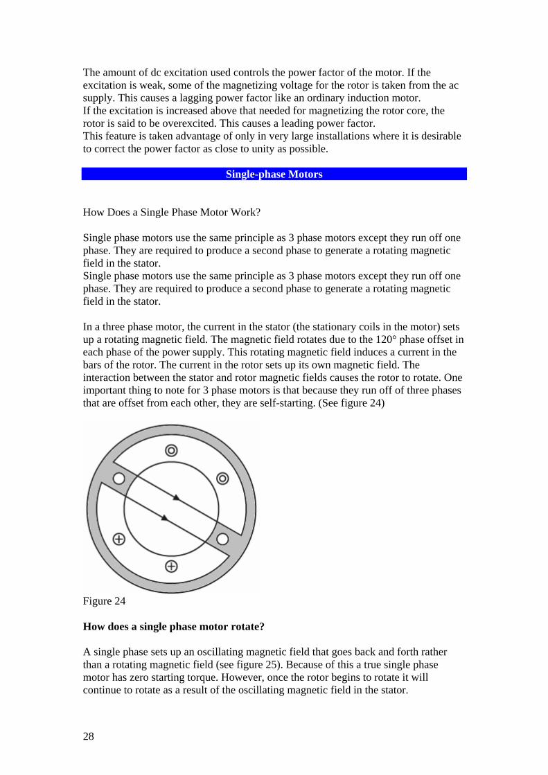
Single-phase Motors How Does a Single Phase Motor Work? Single phase motors use the same principle as 3 phase motors except they run off one phase. They are required to produce a second phase to generate a rotating magnetic field in the stator. Single phase motors use the same principle as 3 phase motors except they run off one phase. They are required to produce a second phase to generate a rotating magnetic field in the stator. In a three phase motor, the current in the stator (the stationary coils in the motor) sets up a rotating magnetic field. The magnetic field rotates due to the 120° phase offset in each phase of the power supply. This rotating magnetic field induces a current in the bars of the rotor. The current in the rotor sets up its own magnetic field. The interaction between the stator and rotor magnetic fields causes the rotor to rotate. One important thing to note for 3 phase motors is that because they run off of three phases that are offset from each other, they are self-starting. (See figure 24)
Figure 24 How does a single phase motor rotate? A single phase sets up an oscillating magnetic field that goes back and forth rather than a rotating magnetic field (see figure 25). Because of this a true single phase motor has zero starting torque. However, once the rotor begins to rotate it will continue to rotate as a result of the oscillating magnetic field in the stator.
28
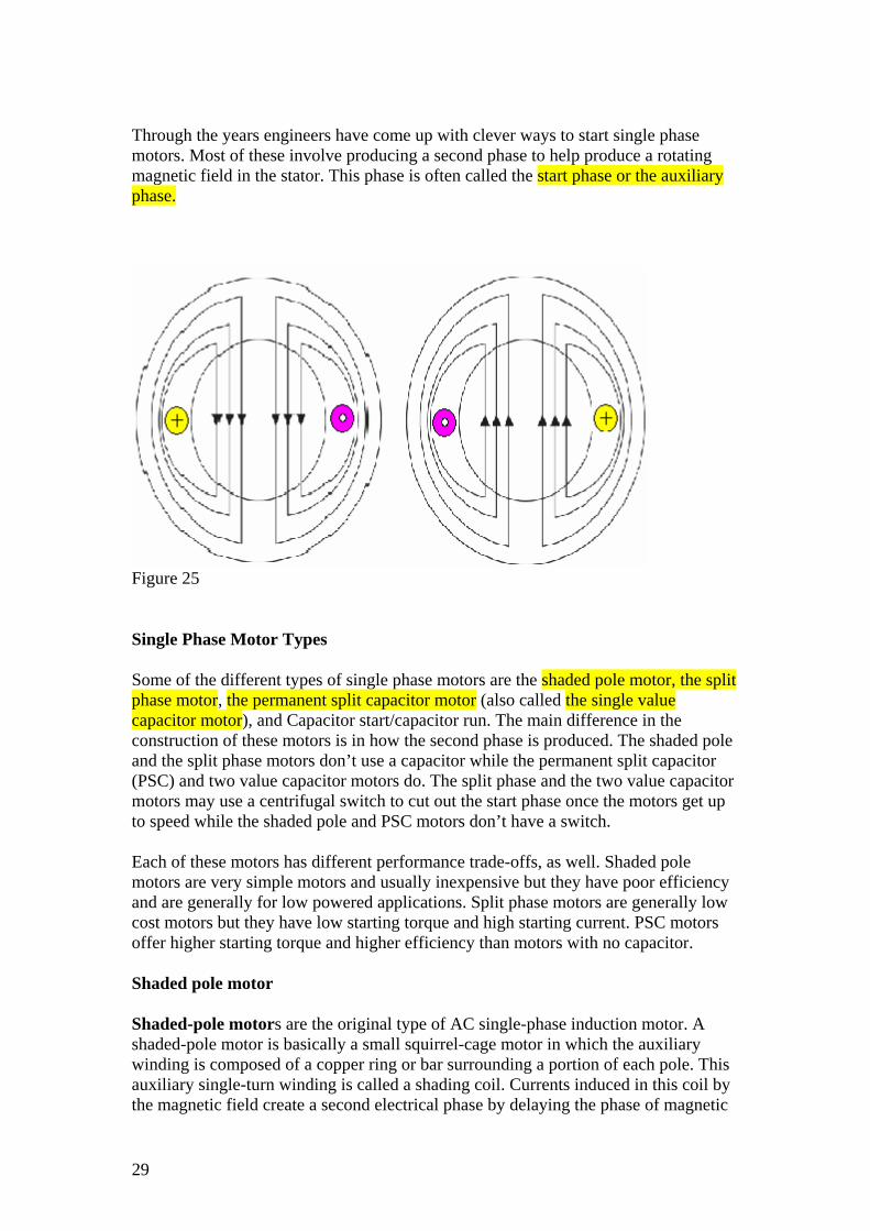
Through the years engineers have come up with clever ways to start single phase motors. Most of these involve producing a second phase to help produce a rotating magnetic field in the stator. This phase is often called the start phase or the auxiliary phase.
Figure 25
Single Phase Motor Types
Some of the different types of single phase motors are the shaded pole motor, the split phase motor, the permanent split capacitor motor (also called the single value capacitor motor), and Capacitor start/capacitor run. The main difference in the construction of these motors is in how the second phase is produced. The shaded pole and the split phase motors don’t use a capacitor while the permanent split capacitor (PSC) and two value capacitor motors do. The split phase and the two value capacitor motors may use a centrifugal switch to cut out the start phase once the motors get up to speed while the shaded pole and PSC motors don’t have a switch.
Each of these motors has different performance trade-offs, as well. Shaded pole motors are very simple motors and usually inexpensive but they have poor efficiency and are generally for low powered applications. Split phase motors are generally low cost motors but they have low starting torque and high starting current. PSC motors offer higher starting torque and higher efficiency than motors with no capacitor.
Shaded pole motor
Shaded-pole motors are the original type of AC single-phase induction motor. A shaded-pole motor is basically a small squirrel-cage motor in which the auxiliary winding is composed of a copper ring or bar surrounding a portion of each pole. This auxiliary single-turn winding is called a shading coil. Currents induced in this coil by the magnetic field create a second electrical phase by delaying the phase of magnetic
29

flux change for that pole (a shaded pole) enough to provide a 2-phase rotating magnetic field. The direction of rotation is from the unshaded side to the shaded (ring) side of the pole. Since the phase angle between the shaded and unshaded sections is small, shaded pole motors produce only a small starting torque relative to torque at full speed. Shaded-pole motors of the asymmetrical type shown are only reversible via disassembly and flipping over the stator, though some similar-looking motors have small, switch-shortable auxiliary windings of thin wire instead of thick copper bars and can reverse electrically. Another method of electrical reversing involves four coils (two pairs of identical coils)
The common, asymmetrical form of these motors (pictured) has only one winding, with no capacitor or starting windings/starting switch, making them economical and reliable. Larger and more modern types may have multiple physical windings, though electrically only one, and a capacitor may be used. Because their starting torque is low, they are best suited to driving fans or other loads that are easily started. They may have multiple taps near one electrical end of the winding, which provides variable speed and power via selection of one tap at a time, as in ceiling fans. Moreover, they are compatible with TRIAC-based variable-speed controls, which often are used with fans. They are built in power sizes up to about 1/6 hp or 125 watts output. For larger motors, other designs offer better characteristics.
Figure 26 (A) illustrates a small C-frame shaded-pole squirrel-cage motor. With the poles shown, the rotor will rotate in the clockwise direction. Figure 26 (B) illustrates Shading coils (copper bars)
Figure 26 A, and B Split phase motor
30
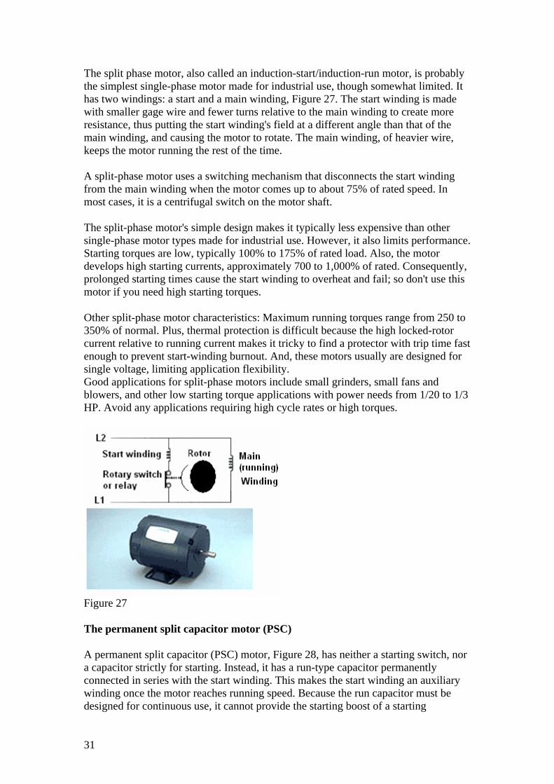
The split phase motor, also called an induction-start/induction-run motor, is probably the simplest single-phase motor made for industrial use, though somewhat limited. It has two windings: a start and a main winding, Figure 27. The start winding is made with smaller gage wire and fewer turns relative to the main winding to create more resistance, thus putting the start winding's field at a different angle than that of the main winding, and causing the motor to rotate. The main winding, of heavier wire, keeps the motor running the rest of the time. A split-phase motor uses a switching mechanism that disconnects the start winding from the main winding when the motor comes up to about 75% of rated speed. In most cases, it is a centrifugal switch on the motor shaft. The split-phase motor's simple design makes it typically less expensive than other single-phase motor types made for industrial use. However, it also limits performance. Starting torques are low, typically 100% to 175% of rated load. Also, the motor develops high starting currents, approximately 700 to 1,000% of rated. Consequently, prolonged starting times cause the start winding to overheat and fail; so don't use this motor if you need high starting torques. Other split-phase motor characteristics: Maximum running torques range from 250 to 350% of normal. Plus, thermal protection is difficult because the high locked-rotor current relative to running current makes it tricky to find a protector with trip time fast enough to prevent start-winding burnout. And, these motors usually are designed for single voltage, limiting application flexibility. Good applications for split-phase motors include small grinders, small fans and blowers, and other low starting torque applications with power needs from 1/20 to 1/3 HP. Avoid any applications requiring high cycle rates or high torques.
Figure 27 The permanent split capacitor motor (PSC) A permanent split capacitor (PSC) motor, Figure 28, has neither a starting switch, nor a capacitor strictly for starting. Instead, it has a run-type capacitor permanently connected in series with the start winding. This makes the start winding an auxiliary winding once the motor reaches running speed. Because the run capacitor must be designed for continuous use, it cannot provide the starting boost of a starting
31

capacitor. Typical starting torques of PSC motors are low, from 30 to 150% of rated load, so these motors are not for hard-to-start applications. However, unlike split-phase motors, PSC motors have low starting currents, usually less than 200% of rated load current, making them excellent for applications with high cycle rates. Breakdown torque varies depending on the design type and application, though it is typically somewhat lower than with a cap start motors. PSC motors have several advantages. They need no starting mechanism and so can be reversed easily. Designs can be easily altered for use with speed controllers. They can also be designed for optimum efficiency and high power factor at rated load. And they're considered to be the most reliable of the single phase motors, mostly because no starting switch is needed. Permanent split capacitor motors have a wide variety of applications depending on the design. These include fans, blowers with low starting torque needs, and intermittent cycling uses such as adjusting mechanisms, gate operators and garage door openers, many of which also need instant reversing.
Figure 28 Capacitor start/capacitor run This type, Figure 29, combines the best of the capacitor-start/induction-run motor and the permanent split capacitor motor. It has a start-type capacitor in series with the auxiliary winding like the capacitor-start motor for high starting torque. And, like a PSC motor, it also has a run-type capacitor that is in series with the auxiliary winding after the start capacitor is switched out of the circuit. This allows high breakdown or overload torque. Another advantage of the capacitor-start/capacitor-run type motor: It can be designed for lower full-load currents and higher efficiency. Among other things, this means it operates at lower temperature than other single-phase motor types of comparable horsepower. The only disadvantage to a cap-start/cap-run motor is its higher price -- mostly the result of more capacitors, plus a starting switch. But it's a real powerhouse, able to handle applications too demanding for any other kind of single-phase motor. These
32

include woodworking machinery, air compressors, high-pressure water pumps, vacuum pumps and other high torque applications requiring 1 to 10 hp.
Figure 29 AC_MOTORS_DOC.doc
33