alfa standard brochure - chi li · pdf filethe alfa standard isolated phase bus systems are...
TRANSCRIPT
alfa standard S.p.A.
HEADQUARTER ADDRESS
Via Giordano Bruno, 1/3 - 24040 Arcene (BG) ITALY
Tel. +39 - (035) 419 3053 Fax +39 - (035) 419 3052 www.alfastandard.it [email protected]
ww
w.g
rafo
com
.it
1
0/06
Summary
General Characteristics
1
Iso Phase Bus Technical Data
2
Standard Technology
3
Auxiliary Equipment
4
Quality Control
5
General Characteristics
Iso Phase Bus Technical Data
Standard Technology
• Conductor• Enclosure• Supporting insulators• Expansion joints• Bushing insulators• Flexible braids• Current transformers • Supporting structures • Wall passage• Transformer & Generator terminal casing
Auxiliary Equipment
• Pressurization• Voltage Transformer Cubicle• Neutral Grounding Cubicle & Star Point Cubicle• Air Forced Cooling System• Hydrogen leakage monitoring
Quality Control
2
4
5
5566777888
9
99
101111
12

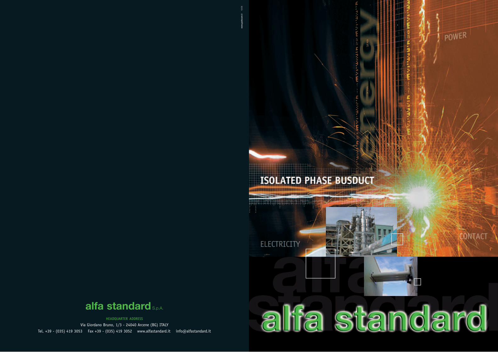
The Alfa Standard Isolated Phase Bus systems are
“continuous enclosure type”, bonded at the extremities
and usually earthed on one end as standard; this
configuration offers more electrical advantages than the
“non-continuous enclosure type” solution.
The magnetic field produced by the conductor current
induces in the enclosure a current, equal to about 90 -
98% of the conductor current, in the opposite direction.
The resulting external magnetic field is negligible.
Structural works, grated panels and rods of reinforced
concrete are therefore not influenced by losses due to
the magnetic induction. The only remaining stresses are
those due to the zero-current component in case of
short circuit currents.
There is no problem with steelwork structures in the
proximity of the continuous enclosure type Isolated
Phase Buses because significant losses and the resultant
rise in temperature cannot happen.
The serious problems found in using conventional bare
bars or cables, for the main circuit connections between
generator and main, auxiliary or voltage transformers, in
all types of power plants (Hydroelectric, Thermoelectric,
Nuclear…) with high ratings of current up to 50 kA at
36 kV, can be solved by the use of Isolated Phase Bus
systems.
Since 1967 Alfa Standard (ISO certified 9001 & 14001)
has been designing, producing and building Isolated
Phase Bus continuous enclosure type, for installations
all over the world.
General Characteristics General Characteristics
cylindrical shape, seam welded aluminium
enclosure.
� No losses on adjacent steelwork.- Due to the
configuration of this system, the induction effect of
the currents i.e. heating and losses in the nearby
components such as steelwork, cables, pipes, etc. is
cancelled.
� Personal security.- The personnel can safely touch
the busbar enclosures because all the accessible
parts are grounded, the temperature rise is in
accordance with the standards (IEC, ANSI, CSA,
etc.) and the voltage rise in the enclosure is
negligible, having a resistive origin only.
� No maintenance.- The degree of protection (IP65)
afforded by AS IPB prevents pollution and foreign
bodies from being deposited on the conductor
support insulators. This removes the risks of a
flashover, even in a corrosive industrial
environment.
This system is an assembly of rigid conductors,
supported by porcelain or epoxy resin insulators and
mounted into an earthed metal enclosure.
The advantages of this solution are:
� Continuous operation.- Not possible for a phase-
to-phase fault to occur. Reduction of the risk of a
phase to earth fault and not possible to transmit
this fault to other phases. Air insulation is the most
reliable of all dielectrics, exhibiting the highest
consistency and resistance to degeneration as well
as the property to easily re-generate itself.
� Simplified support structures.- Greatly reduces
the electromagnetic forces between conductors of
adjacent phases and reduces the forces in bends and
other discontinuities caused by high short-circuit
currents. Allows the possibility of large unsupported
spans because of the high moment of inertia of the
32
Electromagnetic Field

Conductor
The conductors are normally made of aluminium sheets
(Al - 99.5%) rolled and welded to one another so as to
form of a cylinder (in some cases conductor can be
copper 99.9%). Aluminium extruded tube is also used
for diameters ≤ 330 mm.
Several IPB standard sizes carry currents up to 25kA
with natural cooling and 50kA with forced ventilation
cooling. For plant terminals and expansion joints (where
required), flexible connections are provided. When
expansion joints are used, one of the ends of the
expansion connector is factory welded to a conductor
while the other end is field welded to the matching
conductor.
In order to increase the heat-dissipating capacity by
radiation and reduce the temperature rise of the bus
conductors, matt black paint is used on the external
surface.
Iso Phase Bus Technical Data
4
Our IPB are classified into three types depending on the
voltage and current rate. � Type CX for Large Power.- This is Isolated Phase Bus
characterized by the use of aluminum conductor that is
supported by porcelain insulators in an enclosure that is
also made of aluminum. Air is the main insulating medium.
It is used primarily in the transport of large power from
Generator to GSU Transformer in large Thermo-electric,
Nuclear and Hydro Power Plants (up to 50 kA and 36 kV).� Type MR for Medium Power.- This is Isolated Phase Bus
D1D2
II
A
400
400
B
300300 150 150
with the same characteristics as type CX except here the
insulators may be either porcelain or resin. It is used
primarily in the transport of power in medium size
power plants (up to 25 kA and 36 kV).� Type MP for Medium Power.- This is Isolated Phase Bus using
the same technologies of the types CX and MR, designed to
have the most economical solution for the transport of power
in Hydroelectric, Gas Turbine and Combined Cycle Power
Plants of a smaller capacity, which adds the possibility of
housing copper conductor (up to 10 kA and 24 kV).
Standard Technology
Enclosure
The enclosure is made of aluminium sheets (Al - 99.5%)
rolled and butt-welded to form a tubular shape.
Inspection doors are provided to allow access for
assembly or removal of current transformers, expansion
joints, thermometers, flexible joints and other such
equipment.
The three enclosures phases are short circuited at the
ends by the welding of aluminium shunts sized in
accordance with the nominal current carried.
One of these shunts will be grounded for the service
staff’s protection.
As for the conductors, the enclosures are also matt black
painted on the internal surface in order to increase the
heat-dissipating capacity by radiation and reduce the
temperature rise of the accessible element of the
Isolated Phase Bus system.
Furthermore, when required by technical specification or
suggested by enviromental conditions, external surface
may be also painted.
Rated Rated IPB type D1 (mm) D2 (mm) I (mm) A (mm) B (mm)Voltage Current3000A 100 480 680 2340 12804000A 150 540 740 2520 13406000A 200 600 800 2700 1400
up to 9000A 330 720 920 3060 152017,5kV 12000A 450 850 1050 3450 1650
13000A 600 1010 1210 3930 181015000A 700 1110 1310 4230 191018000A 800 1210 1410 4530 201025000A CX 1000 1370 1570 5010 21703000A 100 600 800 2700 14004000A 150 640 840 2820 14406000A 200 700 900 3000 15009000A 330 850 1050 3450 1650
24kV 12000A 450 975 1175 3825 177513000A 600 1110 1310 4230 191015000A 700 1210 1410 4530 201018000A 800 1310 1510 4830 211025000A 900 1410 1610 5130 22103000A 100 800 1000 3300 16004000A 150 860 1060 3480 16606000A 200 900 1100 3600 17009000A 330 1050 1250 4050 1850
36kV 12000A 450 1200 1400 4500 200013000A 600 1310 1510 4830 211015000A 700 1410 1610 5130 221020000A 800 1510 1710 5430 231025000A 900 1610 1810 5730 241030000A CX 1000 1710 1910 6030 2510
MP
MP
MR
MR
CX
CX/MR
Reported values are given as a mere indication; these ones could be changed according to technical and environmental specific requirementsConductor temperature rise: 65°C (149 F). Enclosure temperature rise: 40°C (104 F).
5
6 7
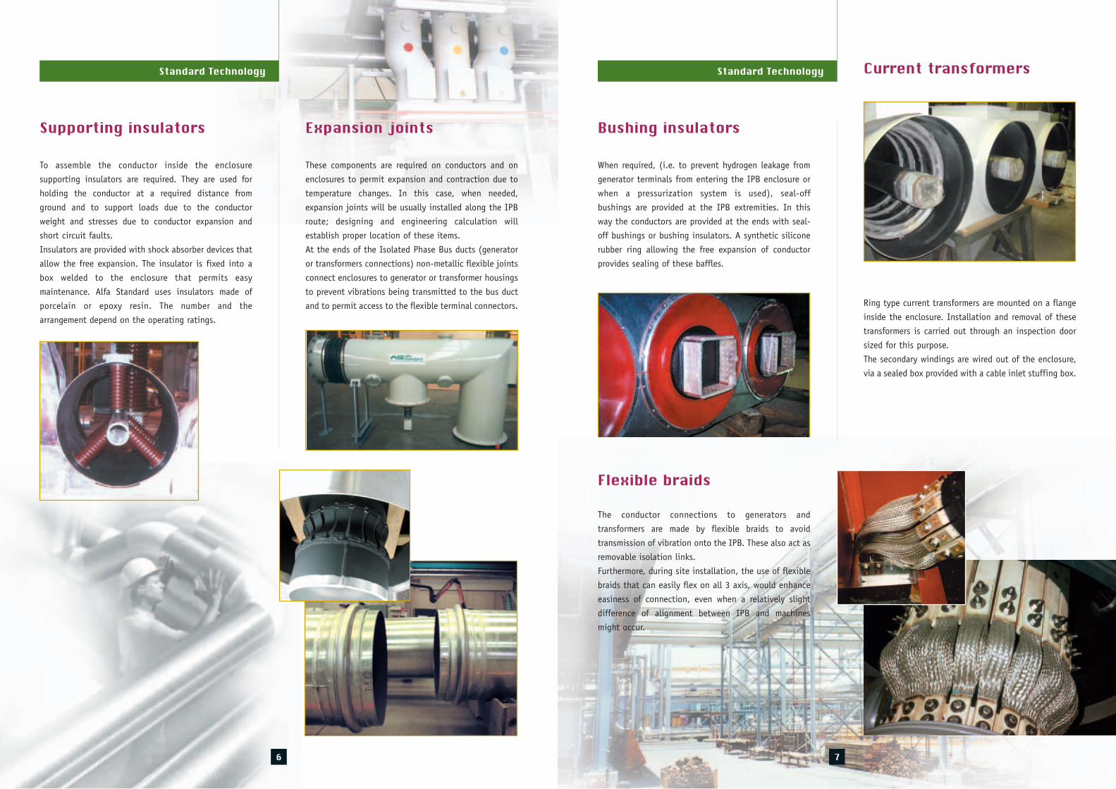
Supporting insulators
To assemble the conductor inside the enclosure
supporting insulators are required. They are used for
holding the conductor at a required distance from
ground and to support loads due to the conductor
weight and stresses due to conductor expansion and
short circuit faults.
Insulators are provided with shock absorber devices that
allow the free expansion. The insulator is fixed into a
box welded to the enclosure that permits easy
maintenance. Alfa Standard uses insulators made of
porcelain or epoxy resin. The number and the
arrangement depend on the operating ratings.
Standard Technology
Expansion joints
These components are required on conductors and on
enclosures to permit expansion and contraction due to
temperature changes. In this case, when needed,
expansion joints will be usually installed along the IPB
route; designing and engineering calculation will
establish proper location of these items.
At the ends of the Isolated Phase Bus ducts (generator
or transformers connections) non-metallic flexible joints
connect enclosures to generator or transformer housings
to prevent vibrations being transmitted to the bus duct
and to permit access to the flexible terminal connectors.
When required, (i.e. to prevent hydrogen leakage from
generator terminals from entering the IPB enclosure or
when a pressurization system is used), seal-off
bushings are provided at the IPB extremities. In this
way the conductors are provided at the ends with seal-
off bushings or bushing insulators. A synthetic silicone
rubber ring allowing the free expansion of conductor
provides sealing of these baffles.
Bushing insulators
The conductor connections to generators and
transformers are made by flexible braids to avoid
transmission of vibration onto the IPB. These also act as
removable isolation links.
Furthermore, during site installation, the use of flexible
braids that can easily flex on all 3 axis, would enhance
easiness of connection, even when a relatively slight
difference of alignment between IPB and machines
might occur.
Flexible braids
Current transformers
Ring type current transformers are mounted on a flange
inside the enclosure. Installation and removal of these
transformers is carried out through an inspection door
sized for this purpose.
The secondary windings are wired out of the enclosure,
via a sealed box provided with a cable inlet stuffing box.
Standard Technology

9
Pressurization
The superior degree of protection (IP65) provided by AS
IPB makes it unnecessary to provide air conditioning of
any type under normal conditions. However, in the case
of a particularly aggressive environment or polluted air,
the IPB system may be pressurized as an additional
safety precaution.
The standard pressurization equipment uses the existing
station air supply and consists of a panel containing:
relief valves, filters, safety valves and control devices.
A dryer and compressor may be also supplied if necessary.
Auxiliary Equipment
Voltage Transformer Cubicle P.T.
Voltage Transformer Cubicles are commonly used to
house P.T.’s for generator metering and protection. These
cubicles also permit the installation of capacitors, surge
arresters and earthing switches if is required.
The P.T. cubicles are normally phase segregated,
although phase isolated cubicles may also be supplied if
required. Low voltage wiring is brought to a common
box for the three phases.
8
Standard Technology
Supporting structures
The enclosures are mounted on rolled aluminium sheet
supports for support of the IPB from above or below,
according to the installation requirement.
These supports are secured to the supporting structure
by means of insulated devices allowing the longitudinal
expansion of the enclosures while maintaining electrical
insulation from the structural work.
Wall passage
This assembly is available and designed even for passing
through light walls, allowing the hermetically sealed
enclosures to pass without exerting any forces on the
walls. When required, wall passages can be supplied
with fire barriers both inside and outside of the IPB.
Wall passages are fully insulated from the busduct.
Transformer & Generatorterminal casingConductor connections to the transformer or generator
terminals are protected by aluminium bolted sheet
casings. Solid aluminium segregations can be provided
for phase to phase and phase to neutral segregation.
11
Auxiliary Equipment
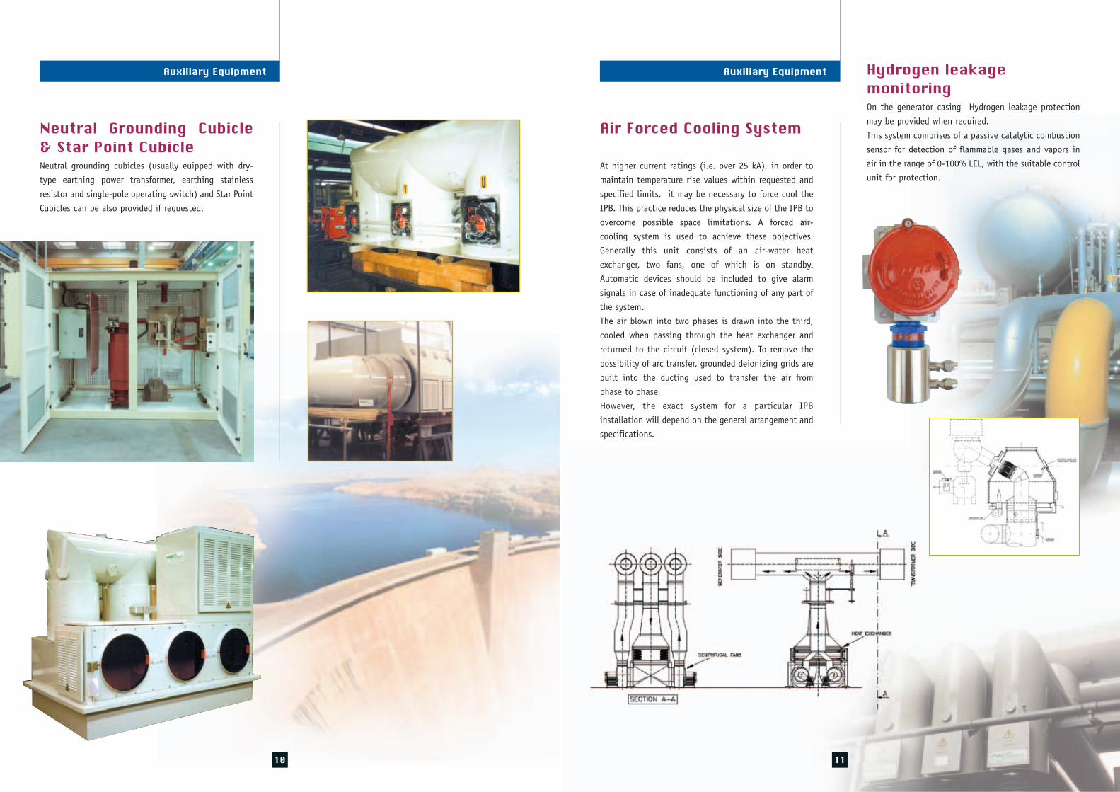
Air Forced Cooling System
At higher current ratings (i.e. over 25 kA), in order to
maintain temperature rise values within requested and
specified limits, it may be necessary to force cool the
IPB. This practice reduces the physical size of the IPB to
overcome possible space limitations. A forced air-
cooling system is used to achieve these objectives.
Generally this unit consists of an air-water heat
exchanger, two fans, one of which is on standby.
Automatic devices should be included to give alarm
signals in case of inadequate functioning of any part of
the system.
The air blown into two phases is drawn into the third,
cooled when passing through the heat exchanger and
returned to the circuit (closed system). To remove the
possibility of arc transfer, grounded deionizing grids are
built into the ducting used to transfer the air from
phase to phase.
However, the exact system for a particular IPB
installation will depend on the general arrangement and
specifications.
10
Neutral Grounding Cubicle& Star Point CubicleNeutral grounding cubicles (usually euipped with dry-
type earthing power transformer, earthing stainless
resistor and single-pole operating switch) and Star Point
Cubicles can be also provided if requested.
Auxiliary Equipment Hydrogen leakage monitoringOn the generator casing Hydrogen leakage protection
may be provided when required.
This system comprises of a passive catalytic combustion
sensor for detection of flammable gases and vapors in
air in the range of 0-100% LEL, with the suitable control
unit for protection.

Quality Control
12
Quality Control
All the materials are purchased from our ApprovedSuppliers List according to our technical specificationsand to the standards IEC, ANSI, and UNI etc. The necessary quality controls are carried out during thedifferent phases of working to guarantee that thefinished product is according to the Costumer’sspecifications and to our qualitative standards. For example, on each completed IPB assembly we carryout tests of insulation at power frequency, measure ofinsulation resistance, checking of painting (adherenceand thickness) and dimensional checks. Type tests suchas, impulse voltage dry test and temperature rise test,might be also performed on IPB at the AS testinglaboratory upon a specific request by client.