©alex doboli 2006 analog to digital converters alex doboli, ph.d. department of electrical and...
TRANSCRIPT

©Alex Doboli 2006
Analog to Digital Converters
Alex Doboli, Ph.D.
Department of Electrical and Computer Engineering
State University of New York at Stony Brook
Email: [email protected]

©Alex Doboli 2006
ADC
The chapter introduces the following aspects:
• Basic concepts of ADC & 1sr and 2nd order ADCs
• ADC are main subsystems in any embedded system
ADC offer high resolution through two mechanisms:– Oversampling: reduces in-band quantization noise– Noiseshaping: eliminates in-band quantization noise
• PSoC implementation of ADC: modulator, decimator, API
©Alex Doboli 2006
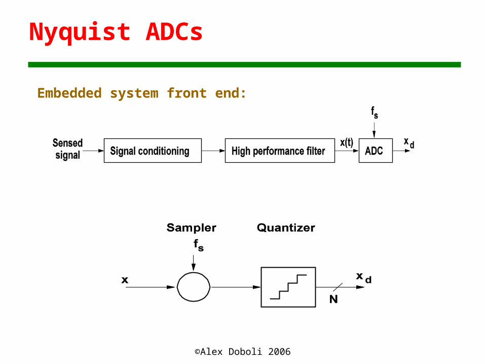
Nyquist ADCs
Embedded system front end:

©Alex Doboli 2006
Sampling
• Collect sufficient data for correctly representing a continuous-time signal

©Alex Doboli 2006
Nyquist Sampling Theorem
• A bandlimited signal can be exactly reconstructed if the samplingFrequency is greater than twice the signal bandwidth
• Nyquist frequency is twice the signal bandwidth

©Alex Doboli 2006
Sampling
aliasing
Xs(f) = X(f) + X(f+/-fs) + X(f+/-2fs) + X(f+/-3fs) + X(f+/-4fs) + …

©Alex Doboli 2006
Quantization
• Quantization is the process of converting the sampled continuous-Valued signals into discrete-valued data

©Alex Doboli 2006
Quantization
• Discretization range: = 2 / (2B - 1)
• Quantization error:er ε (-/2, /2)
White noise
xd = xs + er
©Alex Doboli 2006
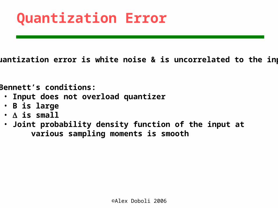
Quantization Error
• Bennett’s conditions:• Input does not overload quantizer• B is large• is small• Joint probability density function of the input at
various sampling moments is smooth
• Quantization error is white noise & is uncorrelated to the input

©Alex Doboli 2006
Quantization Error
• Quantization noise power
• Power spectral density
2e = 2 / 12

©Alex Doboli 2006
Analog to Digital Converter
©Alex Doboli 2006
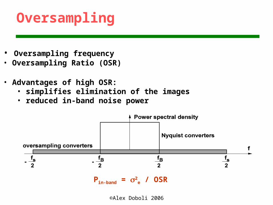
Oversampling
• Oversampling frequency• Oversampling Ratio (OSR)
• Advantages of high OSR:• simplifies elimination of the images• reduced in-band noise power
Pin-band = 2e / OSR
©Alex Doboli 2006
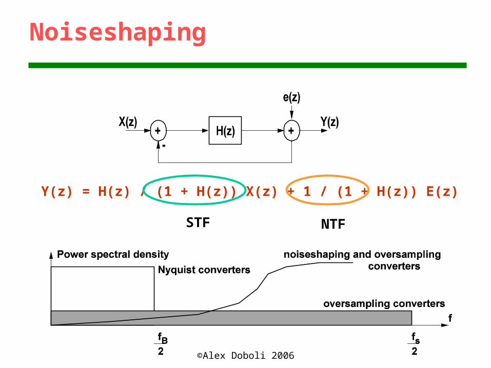
Noiseshaping
Y(z) = H(z) / (1 + H(z)) X(z) + 1 / (1 + H(z)) E(z)
STF NTF

©Alex Doboli 2006
ADC Performance
• Signal-to-noise ratio (SNR):
SNR (dB) = 10 log (signal power) / (in band quantization noise power)
– For sinusoidal input:SNR (dB) = 6.02 B + 1.76 (dB)
SNR (dB) = 6.02 B + 10 log OSR
• Dynamic range (DR):– Ratio between the output power for a sinusoidal input with full-
range amplitude and the output power of the smallest input signal that it can distinguish and quantize
DR (dB) = 10 log (2 / 8) / (in band quantization noise power)B (bits) = (DR (dB) – 1.76) / 6.02

©Alex Doboli 2006
First-order Modulator
yd(t) = z-1 x(t) + (1 – z-1) e(t)
STF = z-1
NTF = 1 – z-1

©Alex Doboli 2006
First-order Modulator: STF & NTF
STF
NTF
High pass

©Alex Doboli 2006
Power Spectrum Density
Frequency of the input signal
noise shaping

©Alex Doboli 2006
Modulator Performance
• Signal to noise ratio for sinusoidal input:
• In-band quantization noise power:
Pin-band = 2 / (9 OSR3)
SNR = 10 log (9 A2 OSR3) / (2 2)

©Alex Doboli 2006
Dynamic Range
34 dB (5 bits)

©Alex Doboli 2006
Dynamic Range vs. OSR
DR=34db (OSR=32)DR=38dB (OSR=64)
DR=42dB (OSR=128)DR=50dB (OSR=256)
(8 bits)

©Alex Doboli 2006
PSoC Implementation
Vin (-Vref, Vref)Vref {VDD/2, 1.6 Vbandgap, Vexternal}OSR = 64Vin = (n – 128) / 128 Vref

©Alex Doboli 2006
PSoC Implementation
modulator– Uses programmable SC blocks
• Decimator– Low pass filtering (eliminates high frequency images)– Downconversion by factor OSR– Sinc2 filter– Implementation: hardware (integration) – software
(differentiation)– Downconversion: timer produces an interrupt after OSR clock
cycles & ISR implements differentiations
• API routines
• Clocks

©Alex Doboli 2006
Modulator Implementation
Single clock for entire design (4 x OSR)

©Alex Doboli 2006
Measured PSD (OSR = 32)

©Alex Doboli 2006
Measured PSD (OSR = 64)
©Alex Doboli 2006
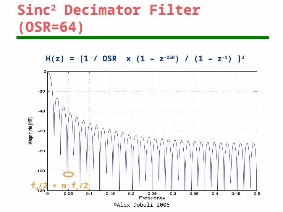
Sinc2 Decimator Filter (OSR=64)
H(z) = [1 / OSR x (1 – z-OSR) / (1 – z-1) ]2
fb/2 + m fs/2

©Alex Doboli 2006
Sinc2 Decimator Filter
• Integration: in hardware using Type 1 decimator block• Differentiation: in software at downconversion rate (4 x
OSR)
• Interrupts at 4 x OSR / fs

©Alex Doboli 2006
Timer ISR

©Alex Doboli 2006
API Routines

©Alex Doboli 2006
API Routines
©Alex Doboli 2006
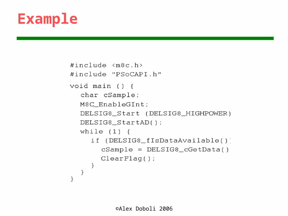
Example
©Alex Doboli 2006
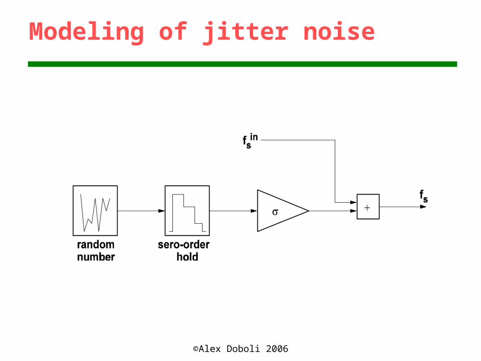
Modeling of jitter noise

©Alex Doboli 2006
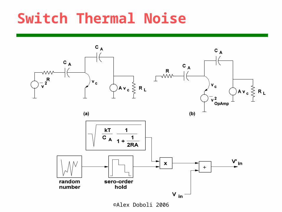
Switch Thermal Noise

©Alex Doboli 2006
Switch Thermal Noise
©Alex Doboli 2006
Switch Thermal Noise

©Alex Doboli 2006
OpAmp Noise
©Alex Doboli 2006
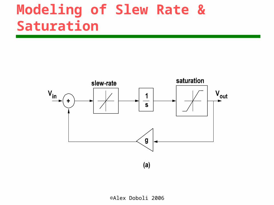
Modeling of Slew Rate & Saturation

©Alex Doboli 2006
Second Order Modulator

©Alex Doboli 2006
Second-order Modulator

©Alex Doboli 2006
PSoC Implementation