alerts and cues on the flight deck: analysis and applications
TRANSCRIPT
NASA/TM—2017–219720
Alerts and Cues on the Flight Deck: Analysis and Applications Benjamin A. Berman San Jose State University Janeen A Kochan San Jose State University Barbara K. Burian NASA Ames Research Center Shawn Pruchnicki San Jose State University Bonny Christopher San Jose State University Evan Silverman San Jose State University
September 2017

ii
NASA STI Program…in Profile
Since its founding, NASA has been dedicated to the advancement of aeronautics and space science. The NASA scientific and technical information (STI) program plays a key part in helping NASA maintain this important role. The NASA STI program operates under the auspices of the Agency Chief Information Officer. It collects, organizes, provides for archiving, and disseminates NASA’s STI. The NASA STI program provides access to the NTRS Registered and its public interface, the NASA Technical Reports Server, thus providing one of the largest collections of aeronautical and space science STI in the world. Results are published in both non-NASA channels and by NASA in the NASA STI Report Series, which includes the following report types:
• TECHNICAL PUBLICATION. Reports of completed research or a major significant phase of research that present the results of NASA programs and include extensive data or theoretical analysis. Includes compilations of significant scientific and technical data and information deemed to be of continuing reference value. NASA counterpart of peer-reviewed formal professional papers but has less stringent limitations on manuscript length and extent of graphic presentations.
• TECHNICAL MEMORANDUM.
Scientific and technical findings that are preliminary or of specialized interest, e.g., quick release reports, working papers, and bibliographies that contain minimal annotation. Does not contain extensive analysis.
• CONTRACTOR REPORT. Scientific and
technical findings by NASA-sponsored contractors and grantees.
• CONFERENCE PUBLICATION. Collected papers from scientific and technical conferences, symposia, seminars, or other meetings sponsored or co-sponsored by NASA.
• SPECIAL PUBLICATION.
Scientific, technical, or historical information from NASA programs, projects, and missions, often concerned with subjects having substantial public interest.
• TECHNICAL TRANSLATION.
English-language translations of foreign scientific and technical material pertinent to NASA’s mission.
Specialized services also include creating custom thesauri, building customized databases, and organizing and publishing research results. For more information about the NASA STI program, see the following: • Access the NASA STI program home
page at http://www.sti.nasa.gov • E-mail your question via to
[email protected] • Phone the NASA STI Help Desk at
(757) 864-9658 • Write to:
NASA STI Information Desk Mail Stop 148 NASA Langley Research Center Hampton, VA 23681-2199
iii
NASA/TM—2017–219720
Alerts and Cues on the Flight Deck: Analysis and Applications Benjamin A. Berman San Jose State University Janeen A Kochan San Jose State University Barbara K. Burian NASA Ames Research Center Shawn Pruchnicki San Jose State University Bonny Christopher San Jose State University Evan Silverman San Jose State University National Aeronautics and Space Administration Ames Research Center Moffett Field, California
September 2017

iv
ACKNOWLEDGMENTS
This work was conducted through Interagency Agreement DTFAWA-11-A-80004 between NASA and the FAA. FAA Human Factors Research and Engineering Division (ANG-C1) provided funding for the project; Dan Herschler served as the technical monitor. The research team would like to thank seven North American air carriers and two aircraft manufacturers for their participation by providing operating and training manuals and system descriptions. We would also like to extend our profound thanks to Captains Brian Baldwin, Dan Boorman, Steve Crofton, Robert Kircher, Mark Maskiell, and Christopher Reed for their invaluable assistance and to JetBlue Airways for the use of their simulation facilities.
Trade name and trademareks are used in this report for identification only. Their usage does not constitute an
official endoresement, either expressed or implied, by the National Aeronautics and Space Administration.
Available from:
NASA STI Program STI Support Services
Mail Stop 148 NASA Langley Research Center
Hampton, VA 23681-2199
This report is also available in electronic form at http://www.sti.nasa.gov or http://ntrs.nasa.gov/
v
Table of Contents
Acronyms ...................................................................................................................... vi Definition of Terms ....................................................................................................... viii Executive Summary ....................................................................................................... 1 1. Introduction .............................................................................................................. 2
1.1 Aircraft Types .................................................................................................... 4 1.2 Alert Types and Sensory Modalities ................................................................... 5
2. Method ...................................................................................................................... 6 2.1 Data Coding ....................................................................................................... 6
2.1.1 Simulator Observations and Subject Matter Expert Input ........................ 7 2.1.2 Matrices .................................................................................................. 7
3. Use of Matrices in Training ........................................................................................ 9 4. Suggested Accident Case Studies ............................................................................... 10 References and Bibliography ......................................................................................... 14 Appendix A. Alerting Systems on the Five Study Aircraft: Brief Overview ................... 21 Appendix B. Study Materials Subjected to Analysis ....................................................... 29 Appendix C. Airbus A320 Matrices ............................................................................... 30 Appendix D. Boeing 737NG Matrices ............................................................................ 30 Appendix E. Boeing B777 Matrices ............................................................................... 30 Appendix F. Bombardier CRJ700 Matrices .................................................................... 30 Appendix G. Embraer EMB190 Matrices ....................................................................... 31 List of Figures: Figure A1. Airbus ECAM dispalys................................................................................. 21 Figure A2. Boeing 737 master caution/fire warning and system annunciator lights......... 24 Figure A3. Boeing EICAS display ................................................................................. 25 Figure A4. Boeing 777 ECL........................................................................................... 26 Figure A5. CRJ700 glareshield warning and caution light switches ................................ 26 Figure A6. CRJ700 EICAS displays 1 and 2 .................................................................. 27 Figure A7. E190 EICAS display .................................................................................... 28 List of Tables: Table 1. Non-Normal Events and Initiating Conditions .................................................. 3 Table 2. Study Transport Category Aircraft .................................................................... 5 Table 3. Study Transport Category Aircraft Avionics ..................................................... 5 Table 4. Matrix Data ...................................................................................................... 8 Table 5. Accident Examples ........................................................................................... 11 Table A1. A320 Failure Levels ...................................................................................... 22 Table A2. A320 Aural Warnings and Meanings ............................................................. 23 Table B1. Study Material with Revision Dates ............................................................... 29

vi
Acronyms
A320 .................................. Airbus 320 AC ..................................... Advisory Circular AGL .................................. above ground level ANP ................................... actual navigation performance AOM ................................. Airline Operations Center B737NG ............................ Boeing 737 Next Generation B777 .................................. Boeing 777 BEA ................................... Bureau d’Enquêtes et d’Analyses (France) C-HIP ................................ communication-human information processing CAST ................................ Commercial Aviation Safety Team CDU .................................. control display unit CFR ................................... Code of Federal Regulations CRC ................................... continuous repetitive chime CRJ .................................... Canadair Regional Jet CRJ700 .............................. Bombardier CL-60 CRJ Series Regional Jet CVR .................................. cockpit voice recorder DATACOMM ................... data communication DSP ................................... display select panel ECAM ............................... Electronic Centralised Aircraft Monitor ECL ................................... electronic checklist ED ..................................... electronic display EICAS ............................... engine indication and crew alerting system EMB190 ............................ Embraer 190 FAA ................................... Federal Aviation Administration (USA) FBW .................................. fly-by-wire FCOM ............................... Flight Crew Operating Manual FCTM ................................ Flight Crew Training Manual FDAWG ............................ Flight Deck Automation Working Group FL ...................................... flight FMC ................................. Flight Management Computer FMGC ............................... flight management guidance computer FMS .................................. flight management system FOM .................................. Flight Operations Manual FWC .................................. flight warning computer GPS ................................... global positioning system GPWS ................................ ground proximity warning system IC ...................................... initiating condition ICAO ................................ International Civil Aviation Organization MCDU ............................... multipurpose control and display unit

vii
MFD ................................. multi-function display NAS ................................... National Airspace System NASA ................................ National Aeronautices and Space Administration ND ..................................... navigation display NextGen ............................ next generation NG ..................................... next generation NTSB ................................ National Transportation Safety Board (USA) PFD ................................... primary flight display QRH .................................. Quick Reference Handbook RNP ................................... required navigation performance SC ...................................... single chime SELCAL ............................ selective calling system STL ................................... Lambert-St. Louis International Airport; St. Louis, Missouri TCAS ................................ traffic collision and avoidance system

viii
Definition of Terms
For the purposes of our analysis and discussion we used the following definitions: aircraft state: The configuration, trajectory, and aerodynamic condition of the aircraft—can be
normal or non-normal alert: A visual, aural, or tactile/haptic signal designed or designated by the airplane manufacturer to
capture pilot attention and provide information about a specific condition or aircraft system state.1
alert cancellation: Manual termination or clearing of a valid alert that has already activated (for example, cancelling a master caution alert by pressing its button). Alert cancellation is performed by the pilots during the normal course of alert response. See also: alert inhibition and alert suppression.
alert inhibition: The automatic or manual prevention of a valid alert from being presented or activated. Alerts can be inhibited automatically by the alerting system (for example, inhibiting a potentially distracting caution light for an air conditioning pack trip when the airplane accelerates through 80 knots during takeoff) or manually by the pilots (for example, setting a “Flap Inhibit” switch to prevent a nuisance ground proximity warning when configuring the aircraft for landing with a non-standard flap setting). See also: alert cancellation and alert suppression.
alert suppression: Automatic prevention, withdrawal from display, or termination of an alert when (1) according to pre-programmed alerting system logic, the data used to trigger the alert are determined to be unreliable or invalid or (2) the manual termination of an activated invalid alert by the pilots after the alerting system has experienced a malfunction. See also: alert cancellation and alert inhibition.
alerting philosophy: A high level description of the design principles that guide the designer and ensure a consistent and coherent interface is presented to the flightcrew, comprising the underlying design put forth by an airframe manufacturer or avionics manufacturer, as to the display of alerts and cues. This philosophy normally considers the (a) reason for implementing an alert, (b) level of alert required for a given condition, (c) characteristics of each specific alert, including types, modality of presentation, conspicuity, threshold for presentation and extinguishing, and inhibition and suppression, if any, and, (d) integration of multiple alerts.
attention-getting signals/methods: Perceptual signals (visual, auditory, or tactile/haptic) designed to attract the flightcrew’s attention in order to obtain the immediate awareness that an alert condition exists. Flashing text is an example of an attention-getting signal.
collector message: An alert message that replaces two or more related alert messages that do not share a common cause or effect. For example, a “DOORS” alert collector message is displayed when more than one entry, cargo, or service access door is open at the same time. See also umbrella message.
command state: The commanded condition or state of an aircraft system or sub-system—can be normal or non-normal. See also system state.
1 For an exhaustive list of the definitions for “alert” used in U.S. regulatory and guidance documents see Yeh, Jo, Donovan, & Gabree, (2013), page 101.

ix
conspicuity: The characteristics of an alert or cue that attract notice or attention. cue: A visual, aural, tactile/kinesthetic, or olfactory signal, which can provide information about the
aircraft or system status, but was not designed by the manufacturer to direct the pilot’s attention in any specific way (e.g., the smell of smoke, or an instrument indication in a non-normal range, but without a change in color, differentiation, or other attention-getting method).
dark and quiet flight deck: The concept that no visual or aural alert will be present on the flight deck when all systems are operating normally.
false alert: An incorrect or spurious alert caused by a malfunction or failure of the alerting system, including a sensor failure.
false positive alert: An alert that is provided to the pilots when the underlying condition associated with the alert is not present.
false negative alert: Failure to alert the flightcrew when the underlying condition associated with an alert is present and (1) regulations require that an alert be presented or (2) the alert system was designed to present an alert.
master aural alert: A general aural alert that is matched to an alert urgency level (i.e., warning or caution) and is used to bring to the flightcrew’s attention that one or more specific alert conditions exist.
master visual alert: A general visual indication that is matched to an alert urgency level (i.e., warning or caution) and is used to bring to the flightcrew’s attention that one or more specific alert conditions exist.
non-normal: Any situation or condition that falls outside of “normal” operations to include: abnormal situations, non-normal situations, emergency situations, NextGen off-nominal. situations (e.g., when actual navigation performance [ANP] is greater than required navigation performance [RNP]).
pilot response: The activity accomplished due to the presentation of an alert or cue as to the existence or potential existence of a situation or condition. Pilot responses may include such things as actions, decisions, consideration of situation/cues/alerts, prioritization of response activities, or search for additional information, among others.
salience: An aspect of an alert or cue that makes it stand out in the environment and able to be perceived by the pilots.
system state: The actual condition of an aircraft system or sub-system—can be normal or non-normal. See also command state.
umbrella message: An alert message (i.e., primary alert message) that is presented in lieu of two or more alert messages that do share a common cause (i.e., secondary/consequential alert messages). Example: A single “engine failure” message is displayed in lieu of multiple messages for malfunctioning electrical generators, generator drives, hydraulic pumps, and bleed air, which would otherwise have been displayed when an engine has failed. See also collector message.

1
Alerts and Cues on the Flight Deck:
Analysis and Applications
Executive Summary In this study, alerts and cues presented on five aircraft types (Airbus 320, Boeing 737NG, Boeing 777, Canadian Regional Jet (CRJ) 700, and Embraer 190) for a 23 initiating conditions leading to one of 10 non-normal events were identified and analyzed. These events and conditions exist in current day operations and are expected to have continued relevance under Next Generation (NextGen) operations. The 10 events, meant to be a “representative sample” from the population of possible non-normal events occurring on aircraft, were:
• aerodynamic stall • uncommanded yaw or roll • hydraulics failure of a single system • single engine failure/fire • in-flight cargo fire/smoke • in-flight hidden cabin fire/smoke • loss/degradation of global positioning system (GPS) • traffic conflict • lateral track or vertical path deviation • air data system failure
We identified and analyzed the following alerts and cues that are presented during these events in the five aircraft types:
• alerts: visual, aural, tactile • cues: visual, aural, tactile/kinesthetic, olfactory
Alerts are intended to provide the pilots with information that equipment is not performing to required specifications (e.g., degraded accuracy), the aircraft is entering an undesired state (e.g., low airspeed), or the aircraft is encountering an environmental hazard (e.g., windshear). Cues that occur due to non-normal situations, such as the smell of smoke during a fire or an indicator pointing to an unusual value for hydraulic pressure, also provide the pilots with information about a situation, although they are not specifically designed by the manufacturer to reliably draw attention and indicate a specific condition. We chose events and initiating conditions to illustrate situations that are made known to the flight crews through:
• alerts only • cues only • both alerts and cues • neither alerts nor cues during the early stages of the event (i.e., hidden cabin smoke/fire)
Data and analyses are presented in the form of matrices (see Appendices C through G) and suggestions for how the matrices might be used in a training environment with professional pilots are provided.

2
1. Introduction Alerts and cues are of critical importance in helping flight crews understand the existence of non-normal conditions and situations on board aircraft and to respond appropriately. Alerts are designed by aircraft and avionics manufacturers and are intended to attract attention and provide the pilots with information that equipment is not performing to required specifications (e.g., degraded accuracy), the aircraft is entering an undesired state (e.g., low airspeed), or the aircraft is encountering an environmental hazard (e.g., windshear). Cues that occur due to non-normal situations, such as the smell of smoke during a fire or an indicator pointing to an unusual value for hydraulic pressure, also provide the pilots with information about a situation, although they are not specifically designed by the manufacturer to reliably draw attention and indicate a specific condition. In this study we identified the alerts and cues that would be present for 23 specific conditions associated with 10 different non-normal events. The set of events selected for this study are illustrative of the range of events involving the kinds of alerting, including absence of alerting, found on today’s airliners (i.e., a “representative set” of events). We specifically considered the level of criticality of the chosen events and their importance to National Airspace System (NAS) operations both currently and under NextGen. Our 10 events came from four major loci of origin:
• events external to the aircraft (e.g., wake encounter) • major system failures (e.g., engine failure) • secondary system failures (e.g., hydraulic system failure) • flight crew errors (e.g., incorrect automation mode selection for required navigation
performance[RNP] approach) For each of the 10 events we identified one or more initiating condition (IC), each representing a realistic entry into the condition (i.e., reason for or cause of the event), and determined differences in how the condition is experienced and to be handled by flight crews (Table 1). The 10 study events and 23 ICs analyzed are listed in Table 2. The choice of events is consistent with the International Civil Aviation Organization (ICAO) Doc 9995 Manual of Evidence-Based Training (ICAO, 2012) with respect to the characteristics of events used in aircrew training. The study events analyzed consider immediacy, complexity, degradation of aircraft control, loss of instrumentation, and management of consequences. Also, we specifically considered false positive alerts as well as false negative alerts when relevant to the event and the alerting system involved. The events and ICs were chosen to provide at least one example of each:
• both alerted and cued • cued but not alerted • neither cued nor alerted

3
Table 1. Non-Normal Events and Initiating Conditions (ICs)
Event (Number of Initiating Conditions) Initiating Conditions
Aerodynamic stall (4)
• High altitude airspeed decay with turbulence, autopilot engaged • Increasing load factor in nose-low, high bank upset, autopilot
disengaged • Wing ice accumulation • False stall warning during takeoff rotation
Uncommanded yaw or roll (3) • Wake encounter • Uncommanded rudder deflection or rudder pedal kicks • Uncommanded aileron/spoiler/flap/slat deflection
Hydraulics failure, single system (1)
• Complete fluid loss for the single most critical hydraulic system during cruise flight
Single engine failure/fire (4)
• Engine failure after V1 and prior to V2 • Engine failure in cruise flight with autopilot engaged • Engine fire after V1 and prior to V2 • False fire warning from engine bleed leak, during takeoff after
V1 and before V2
In-flight cargo fire/smoke (2)
• Ignition of cargo leading to extinguishable belly cargo compartment fire, in cruise
• Dust/moisture leading to false indication of smoke in a cargo compartment, in cruise
In-flight hidden cabin fire/smoke (1)
• Ignition from short circuit in electrical wiring hidden behind cabin walls or ceiling
Loss/degradation of GPS (2)
• Poor GPS satellite availability or geometry leading to decreased GPS signal integrity
• Intentional spoofing leading to false position input from GPS to the flight management system (FMS)
Traffic conflict (2)
• Traffic conflict in air traffic control (ATC) radar environment (operational error or pilot deviation
• Traffic conflict in NextGen air traffic management [ATM] environment (ground-based sequencing/metering error or data communication [DATACOMM] error)
Lateral track or vertical path deviation beyond limit (1)
• In RNP approach and similar NextGen terminal area operations, the aircraft’s failure to follow the centerline of the lateral track and/or vertical path within the required deviation limits (e.g., RNP value for lateral track), due to excess wind, autopilot failure, failure to engage autopilot/ mode, or specific FMS/autopilot inability to meet specifications
Air data system failure (3)
• Blocked pitot source (captain’s or left source) • Blocked pitot source (all sources blocked, first partially and
inconsistently, then completely), with at least one blocked pitot drain, during climb
• Air data computer failure (single air data module or unit)

4
In other words, some of the study events/conditions would be made known to pilots primarily or only through alerts and others primarily or only through cues. Many are both alerted and cued and one (hidden cabin smoke) is neither alerted nor cued on the flight deck, although cues in the cabin would be evident but only after the event had progressed to a certain degree. Some events have a short timeframe for response (e.g., uncommanded roll due to wake encounter) and others have a much longer timeframe with implications for the rest of the flight through landing (e.g. hydraulics failure). We also analyzed the erroneous alerts presented for some false conditions (e.g., false aerodynamic stall warning), particularly if they have the potential to be highly confusing for flight crews. We included events that might be considered to be abnormal or emergencies, as well as some that are considered off-nominal in NextGen operations (i.e., not desirable, but not necessarily considered an abnormal or emergency event). For these events we analyzed the alerts and cues presented to pilots in the following sensory modalities:
• visual alerts • aural alerts • tactile alerts • visual cues • aural cues • tactile/kinesthetic cues • olfactory (smell) cues
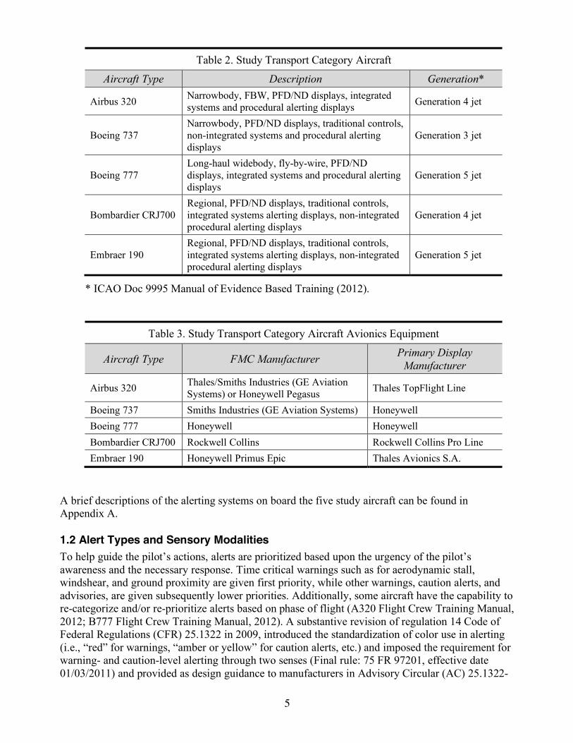
We considered these to be representative of what pilots may experience under normal and non-normal conditions in currently operated transport category aircraft. 1.1 Aircraft Types We selected five aircraft types for use in this study (Table 2), which encompass different alerting approaches, technology generations, aircraft sizes, and typical mission profiles. Four aircraft manufacturers, designs initiated from the 1960s through the 2000s, with aircraft passenger capacity of 70 through 350, and regional through long haul intercontinental missions are represented. The study sample included aircraft that are and are not fly-by-wire (FBW), single and double aisle, and are typically operated in the United States by both mainline and regional air carriers. As evidenced in Table 2, first and second generation aircraft were not included in the study due to the fewer numbers of these aircraft still in operation today. We included two aircraft types from one manufacturer to facilitate evaluation of design evolution over time. The typically installed avionics (e.g., Flight Management Computer [FMC] and flight displays) found on the study aircraft are listed in Table 3.
5
Table 2. Study Transport Category Aircraft
Aircraft Type Description Generation*
Airbus 320 Narrowbody, FBW, PFD/ND displays, integrated systems and procedural alerting displays Generation 4 jet
Boeing 737 Narrowbody, PFD/ND displays, traditional controls, non-integrated systems and procedural alerting displays
Generation 3 jet
Boeing 777 Long-haul widebody, fly-by-wire, PFD/ND displays, integrated systems and procedural alerting displays
Generation 5 jet
Bombardier CRJ700 Regional, PFD/ND displays, traditional controls, integrated systems alerting displays, non-integrated procedural alerting displays
Generation 4 jet
Embraer 190 Regional, PFD/ND displays, traditional controls, integrated systems alerting displays, non-integrated procedural alerting displays
Generation 5 jet
* ICAO Doc 9995 Manual of Evidence Based Training (2012).
Table 3. Study Transport Category Aircraft Avionics Equipment
Aircraft Type FMC Manufacturer Primary Display Manufacturer
Airbus 320 Thales/Smiths Industries (GE Aviation Systems) or Honeywell Pegasus Thales TopFlight Line
Boeing 737 Smiths Industries (GE Aviation Systems) Honeywell Boeing 777 Honeywell Honeywell Bombardier CRJ700 Rockwell Collins Rockwell Collins Pro Line Embraer 190 Honeywell Primus Epic Thales Avionics S.A.
A brief descriptions of the alerting systems on board the five study aircraft can be found in Appendix A. 1.2 Alert Types and Sensory Modalities To help guide the pilot’s actions, alerts are prioritized based upon the urgency of the pilot’s awareness and the necessary response. Time critical warnings such as for aerodynamic stall, windshear, and ground proximity are given first priority, while other warnings, caution alerts, and advisories, are given subsequently lower priorities. Additionally, some aircraft have the capability to re-categorize and/or re-prioritize alerts based on phase of flight (A320 Flight Crew Training Manual, 2012; B777 Flight Crew Training Manual, 2012). A substantive revision of regulation 14 Code of Federal Regulations (CFR) 25.1322 in 2009, introduced the standardization of color use in alerting (i.e., “red” for warnings, “amber or yellow” for caution alerts, etc.) and imposed the requirement for warning- and caution-level alerting through two senses (Final rule: 75 FR 97201, effective date 01/03/2011) and provided as design guidance to manufacturers in Advisory Circular (AC) 25.1322-
6
1, (Federal Aviation Administraation [FAA], 2010). AC 25.1322-1 identifies six different alert functional elements: warning alerts, time-critical warning alerts, master visual and aural alerts, caution alerts, and advisory alerts. In practice, these elements are grouped into three major alert types (warnings, cautions, and cdvisories) and some manufacturers add a fourth type: Status. To meet the requirements of 14 CFR 25.1322, an appropriate combination of alerting system presentation elements must be used; these elements typically include: master visual alerts, visual alert information (most often textual, but also includes failure flag indications and other types of unique indicators on flight deck displays), master aural alerts, voice information, unique tones (unique sounds), and tactile or haptic information (FAA 2010)2. Visual indicators and visual alerts are typically in the flightcrew’s expected scan range or field of view, increasing the likelihood that they will be noticed. Some examples of visual alerts are: illuminated lights on annunciator panels, flashing boxes on the electronic flight displays, master warning and master caution lights, and text messages on the flight deck’s crew alerting system or FMS displays. Auditory alerts can be stand-alone or may be used in conjunction with a visual alert. The high salience of auditory warnings makes them prevalent in the cockpit. Some examples of auditory alerts are: horns, whistles, sirens, bells, and tones, which vary in pulse and burst (Burt, Bartolome, Burdette & Comstock, 1995), as well as synthetically generated voice alerts (e.g., “Pull up! Pull up!”). Although only used for a small number of conditions, tactile/haptic alerts, such as the stickshaker, are found in many transport category airplanes and are commonly used to alert pre-stall conditions. 2. Method The primary data sources for the study were systems, training, and crew operations manuals for the five aircraft types (see Table B1 in Appendix B). For comprehensiveness and to facilitate cross-validation of the information, we obtained and referenced the equivalent manuals for each aircraft type from at least two different air carriers. As is customary in our research, we committed to the airline participants that we would not refer to them by name and would de-identify any materials to be specifically quoted or reproduced in our work. Most of the manuals that we obtained had been customized by the air carriers but were based on the production documentation delivered from by the original equipment manufacturers (Airbus, Boeing, Bombardier, and Embraer). They contributed valuable information relative to how the air carriers had tailored the contents of each. 2.1 Data Coding We identified all of the alerts and cues that might be present for each event IC and then populated data fields in matrices for each alert and cue identified (e.g., “threshold for alert or cue to be presented”). The researchers’ personal flight operation and human factors expertise was used when defining likely pilot reactions and needed response to alerts and cues for each referenced event. The coding based on these judgments, as well as all other coding, was affirmed through research team review. A member of the research team, who was not involved in initial matrix development, reviewed all completed matrices and identified potential inconsistencies and missing data. Inconsistencies were resolved through consultation of the source documents and consensus judgment, when necessary.
2 Although haptic and tactile feedback/alerting are different, within the industry they are often confused or a distinction between them is not made. Because of this, no distinction will be made between them in this report.
7
Researchers conducting this study have extensive understanding of aircraft display and alerting system architecture and operation. One researcher has extensive training and line operational experience on B777 and B737 aircraft and another has similar expertise with CRJ aircraft. A third researcher involved in matrix development also has extensive airline experience on a variety of aircraft types. 2.1.1 Simulator Observations and Subject Matter Expert Input For the two study aircraft with which our coders lacked personal flight training and experience (A320 and EMB190), we supplemented printed documentation with site visits to airlines operating these aircraft types. Prior to the visits, we developed a protocol for evaluating the events and initiating conditions using FAA-approved, Level D pilot training simulators operated by the airlines. During the site visits, we observed the simulation of the events and conditions in the A320 and EMB190 simulators as they were performed by training captains who were line-qualified in the respective type. We recorded video and audio of the simulations, and extracted data from these sources through review by the researchers. To control for the possibility of the simulations being inaccurate or incomplete, we only used the simulation data to supplement and cross-verify the data being obtained from our standard documentation from the manuals. We also held extensive discussions with the training captains, with follow-up communication, to address simulator limitations and how our events and ICs might transpire differently in real aircraft. When necessary, we supplemented and verified our understanding of the design and function of the five aircraft alerting systems through informal discussions with other airline and aircraft manufacturer personnel. Thus, multiple data sources—text, experiential, observational, and face-to-face and phone inquiries—were utilized to populate the data in the matrices. 2.1.2 Matrices The 23 completed matrices for each of the five aircraft included in this study can be found in Appendices C through G. Data analyzed and included in each matrix are described in Table 4 and appear in either tabular format or as bullet lists. Cells in the matrix tables that are “not applicable” (e.g., a tactile alert does not exist for an IC) are either left blank or the word “none” appears.

8
Table 4. Matrix Data Category Descriptor
Sensory modality Alerts and cues are grouped according to the sensory mode in which they are presented or available with all alert sensory modes listed first followed by the cue sensory modes.
Alert or cue name A description of each visual, aural, tactile/kinesthetic, and/or olfactory alert or cue present for the IC of event.
Threshold for alert or cue to be presented
When the alert or cue would be initially presented in the particular IC.
Type of alert Warning, caution, advisory, status. Other issues with regard to alert or cue Issues not considered in other categories, if present.
When is alert inhibited/ suppressed or when is cue masked, if any
When alerting system inhibits/suppresses an alert or other conditions resulting in the masking of the cue, if present.
How alert or cue is terminated What features in the IC or pilot response would terminate the alert or cue.
Expected pilot response Specific procedures or general processes expected of the pilot. How does pilot know condition is resolved/recovered
A description of the change in alerts and cues, if any, signifying to the pilot that the condition is resolved.
Issues with regard to multiple concurrent non-normal conditions
Confounding aspects associated with other potential concurrent non-normal conditions, if present.
A little more information is warranted with regard to the matrix category of “expected pilot response.” Although it may appear that pilot response to alerts should be a relatively straightforward task, incident and accident reports indicate that this is not so (Flight Data Working Group [FDAWG], 2013). Problems may first arise during the initial stage when operators fail to detect the alert, possibly related to insufficient monitoring (FDAWG, 2013; Moray, 1980; Wickens, 1984). There are several systematic reasons as to why this might occur. For example, the alert may not be salient enough to grab the pilots’ attention, or the placement of a visual alert may be out of the pilot’s normal range of view. Pilots might also not detect an alert because they are dealing with another issue that occupies their attention. Signal detection and the ability to perceive that a specific change has taken place relative to a stimulus within a sensory modality (e.g. visual, auditory, etc.) is obviously essential if adequate and appropriate pilot response is to occur. Pertinent issues associated with these factors and others were considered and are reflected in the matrices.

9
3. Use of Matrices in Training The alerting matrices provide a framework for elements that can be incorporated into various phases of pilot training. The following are suggestions of how they can be used by instructors in developing different training modules for ground school/distance learning and for simulator training.
• Referencing the matrices, develop a ground school or computer-based training module about the basic philosophy of aircraft alerting systems and how, in general, pilots are expected to respond to alerts and cues (in conjunction with guidance set forth in non-normal checklists). Select an event and an alert that occurs during it, then follow the matrix from the alert through to the pilots’ responses:
– type of alert – sensory modality (channel) through which the alert is delivered, also discussing the
advantages and challenges of that channel – triggers/threshold for alert presentation – other alerts and cues that may be presented before, together with, and after the alert – the pilots’ response to these alerts and any challenges in responding correctly
• The matrices include information about the threshold that must be met for the presentation of
some alerts as well as when some alerts are inhibited or suppressed. Discuss these three aspects associated with alerting and consider the pros and cons of alert inhibition and suppression in different conditions.
• In the matrices, note the number of alerts or cues that are presented in the same sensory
modality for a given condition (e.g., visual). Discuss issues associated with attention to alerts, division of attention among alerts and cues, and sensory overload.
• Develop a ground school or computer-based training module to address how cues can be used
to confirm, disconfirm, or refine one’s understanding of presented alerts. As part of the module, discuss various cognitive biases that may come into play when presented with alerts and cues (e.g., confirmation bias).
•The matrices for some events and initiating conditions identify specific issues associated with
alerts in multiple failure conditions. Consider likely multiple failure conditions and the range and type of alerts and cues available. Discuss issues in developing an appropriate mental model of the condition(s) and desired crew responses, drawing, in part, upon company philosophy, policies, and procedures.
• Use the matrix information to consider how pilots may be challenged by Next-Gen operations
such as RNP approaches, and specifically train the most effective interpretation and use of the available alerts and cues.
– Example: Loss/degradation of GPS matrix – Example: Track or path deviation matrix – Example: Traffic conflict matrix
• Consider the role that monitoring has with regard to alert and cue identification and response. Are there certain monitoring techniques that are particularly effective in helping to predict the occurrence of some alerts and ways to quickly distinguish false and true alerts from each

10
other? Information in the matrices can then be used to develop simulator scenarios that allow pilots to experience and practice distinguishing false from valid alerts.
– Example: Stall warning during takeoff rotation: compare the alerts and cues of the valid and false warning conditions
– Example: Fire warning during takeoff rotation and cargo fire warning: compare the alerts and cues of the valid and false warning conditions
• Develop simulator scenarios involving (a) unexpected events that may startle if they occur
without warning, (b) events for which the alerts and cues are subtle and may not reliably grab the pilots’ attention, (c) failures leading to the absence of an expected alert, (d) combinations of alerts and cues presented sequentially or simultaneously, that may themselves be part of what makes a situation unexpected, challenging, or stressful. The matrices provide some examples of such events.
– Example: Stall without normal stall warning and with subtle secondary cues – Example: Multiple air data source failure
• Use the matrix information to develop simulator scenarios that allow pilots to experience and practice recognizing and reacting to loss of automation/automation reversions.
– Example: Stall event with FBW system degradation to alternate mode or law – Example: Loss of autopilot with air data computer failure
• Develop simulator scenarios that allow pilots to experience and practice interpreting and reacting to alerts that may be generated by secondary conditions (preceding or consequent to a main system failure), depending on the aircraft type.
– Example: Hydraulic system failure matrix – Example: Engine failure in cruise condition matrix
• Use the matrix information to develop simulator scenarios that allow pilots to experience and practice recognizing and reacting to an un-alerted event, particularly one in which the pilots may not readily recognize the condition or condition severity based on the available cues.
– Example: In-flight hidden cabin fire/smoke matrix. – Example: Stall in icing conditions
• Outside of training activities, the matrix format and contents can also be used to guide event analysis within the Safety Management System.
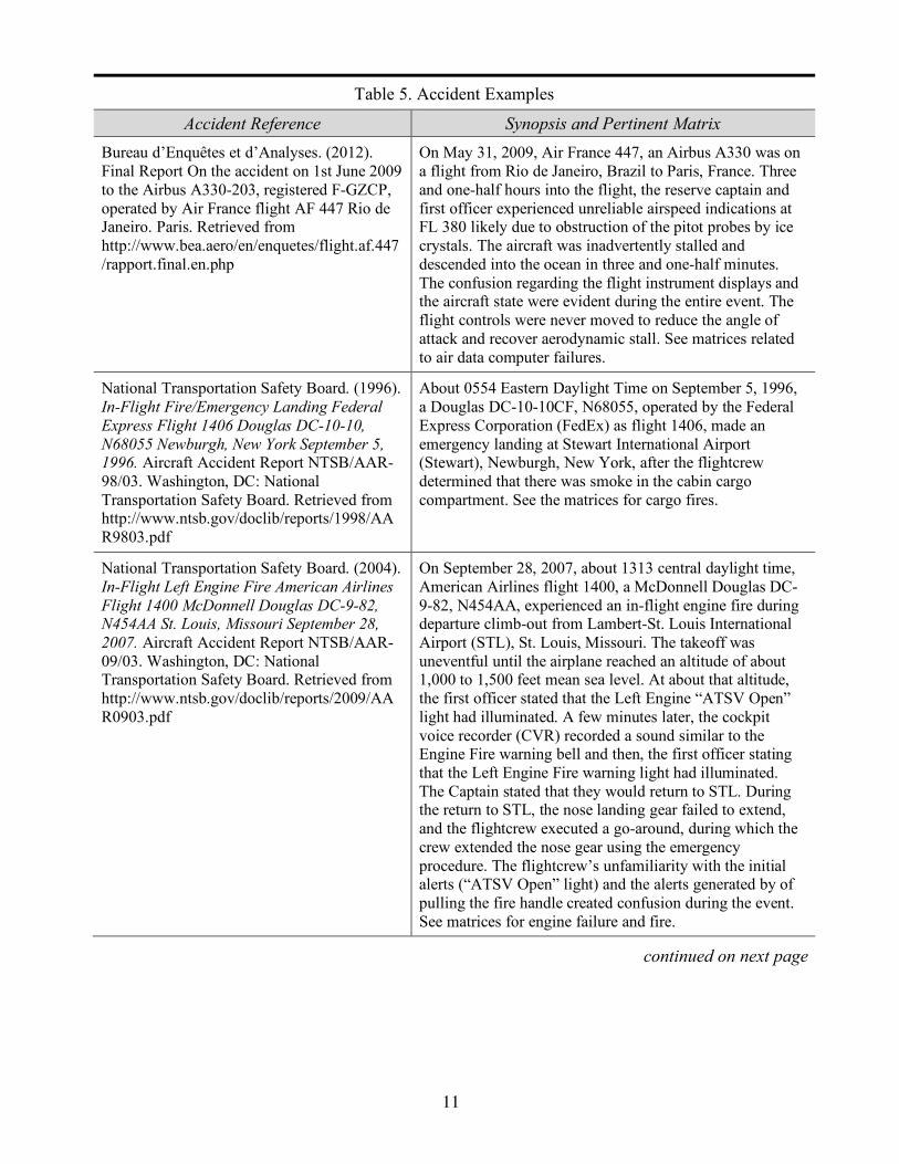
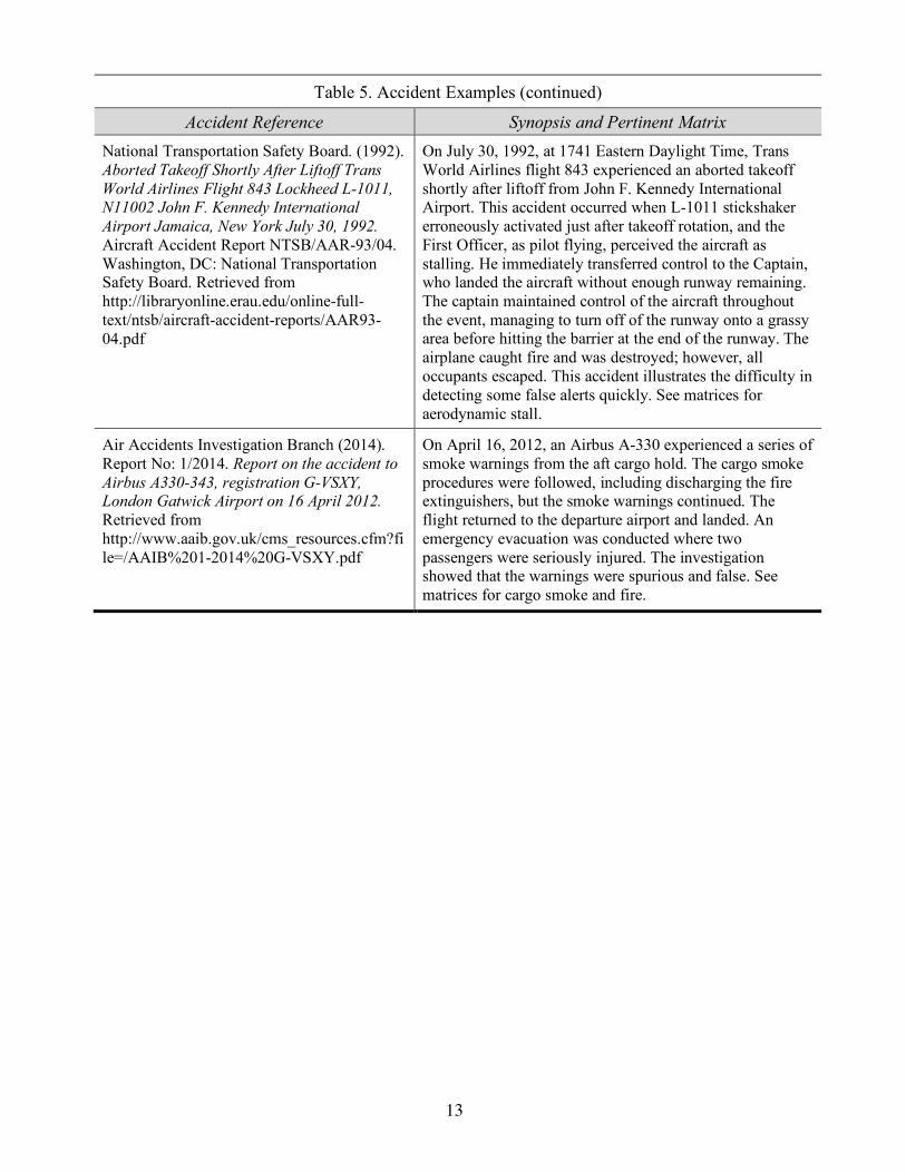
4. Suggested Accident Case Studies Accidents identified in Table 5 can be used as case studies in conjunction with the matrix or matrices that pertain to the alerting components associated with these events. Specific alerts and cues that were reported in the accident reports can be analyzed using the pertinent matrix as a guide. Group discussions can be generated by focusing on the contributions (both positive and negative) from the alerts and cues generated during the event.
11
Table 5. Accident Examples
Accident Reference Synopsis and Pertinent Matrix Bureau d’Enquêtes et d’Analyses. (2012). Final Report On the accident on 1st June 2009 to the Airbus A330-203, registered F-GZCP, operated by Air France flight AF 447 Rio de Janeiro. Paris. Retrieved from http://www.bea.aero/en/enquetes/flight.af.447/rapport.final.en.php
On May 31, 2009, Air France 447, an Airbus A330 was on a flight from Rio de Janeiro, Brazil to Paris, France. Three and one-half hours into the flight, the reserve captain and first officer experienced unreliable airspeed indications at FL 380 likely due to obstruction of the pitot probes by ice crystals. The aircraft was inadvertently stalled and descended into the ocean in three and one-half minutes. The confusion regarding the flight instrument displays and the aircraft state were evident during the entire event. The flight controls were never moved to reduce the angle of attack and recover aerodynamic stall. See matrices related to air data computer failures.
National Transportation Safety Board. (1996). In-Flight Fire/Emergency Landing Federal Express Flight 1406 Douglas DC-10-10, N68055 Newburgh, New York September 5, 1996. Aircraft Accident Report NTSB/AAR-98/03. Washington, DC: National Transportation Safety Board. Retrieved from http://www.ntsb.gov/doclib/reports/1998/AAR9803.pdf
About 0554 Eastern Daylight Time on September 5, 1996, a Douglas DC-10-10CF, N68055, operated by the Federal Express Corporation (FedEx) as flight 1406, made an emergency landing at Stewart International Airport (Stewart), Newburgh, New York, after the flightcrew determined that there was smoke in the cabin cargo compartment. See the matrices for cargo fires.
National Transportation Safety Board. (2004). In-Flight Left Engine Fire American Airlines Flight 1400 McDonnell Douglas DC-9-82, N454AA St. Louis, Missouri September 28, 2007. Aircraft Accident Report NTSB/AAR-09/03. Washington, DC: National Transportation Safety Board. Retrieved from http://www.ntsb.gov/doclib/reports/2009/AAR0903.pdf
On September 28, 2007, about 1313 central daylight time, American Airlines flight 1400, a McDonnell Douglas DC-9-82, N454AA, experienced an in-flight engine fire during departure climb-out from Lambert-St. Louis International Airport (STL), St. Louis, Missouri. The takeoff was uneventful until the airplane reached an altitude of about 1,000 to 1,500 feet mean sea level. At about that altitude, the first officer stated that the Left Engine “ATSV Open” light had illuminated. A few minutes later, the cockpit voice recorder (CVR) recorded a sound similar to the Engine Fire warning bell and then, the first officer stating that the Left Engine Fire warning light had illuminated. The Captain stated that they would return to STL. During the return to STL, the nose landing gear failed to extend, and the flightcrew executed a go-around, during which the crew extended the nose gear using the emergency procedure. The flightcrew’s unfamiliarity with the initial alerts (“ATSV Open” light) and the alerts generated by of pulling the fire handle created confusion during the event. See matrices for engine failure and fire.
continued on next page

12
Table 5. Accident Examples (continued)
Accident Reference Synopsis and Pertinent Matrix Transportation Safety Board of Canada. (1998). In-Flight Fire Leading to Collision with Water Swissair Transport Limited McDonnell Douglas Md-11 HB-IWF Peggy’s Cove, Nova Scotia 5nm SW 2 September 1998.Aviation Investigation Report, Report Number A98H0003. Retrieved from http://www.tsb.gc.ca/eng/rapports-reports/aviation/1998/a98h0003/a98h0003.pdf
On 2 September 1998, Swissair Flight 111 departed New York, United States of America, at 2018 Eastern Daylight Savings time on a scheduled flight to Geneva, Switzerland. About 53 minutes after departure, while cruising at flight level 330, the flightcrew smelled an abnormal odor in the cockpit. They agreed that the origin of the anomaly was the air conditioning system. When they assessed that what they had seen or were now seeing was definitely smoke, they decided to divert. They initially began a turn toward Boston but changed their destination to Halifax International Airport. They leveled off to jettison fuel but were unaware that a fire was spreading above the ceiling in the front area of the aircraft. About 13 minutes after the abnormal odor was detected, the aircraft’s flight data recorder began to record a rapid succession of aircraft systems-related failures. The flightcrew declared an emergency and indicated a need to land immediately but ended up crashing into the ocean. See matrices for hidden cabin fires.
National Transportation Safety Board.. (1994). In-Flight Icing Encounter and Loss of Control Simmons Airlines, d.b.a. American Eagle Flight 4184 Avions de Transport Regional (ATR) Model 72-212, N401AM Roselawn, Indiana October 31, 1994 Volume 1: Safety Board Report. Aircraft Accident Report NTSB/AAR-96/01. Washington, DC: National Transportation Safety Board. Retrieved from https://www.ntsb.gov/doclib/reports/1996/AAR9601.pdf
On October 31, 1994, at 1559 Central Standard Time, an Avions de Transport Regional, model 72-212 (ATR 72) leased to and operated by Simmons Airlines, Incorporated, and doing business as American Eagle flight 4184, crashed during a rapid descent after an uncommanded roll excursion. The airplane was in a holding pattern and descending to a newly assigned altitude of 8,000 feet when the initial roll excursion occurred. The loss of control was attributed to a sudden and unexpected aileron hinge moment reversal that occurred after a ridge of ice accreted beyond the deice boots. This report shows how attending to cues can provide information regarding hazards when there is a lack of alerting. See matrices for uncommanded yaw and roll.
National Transportation Safety Board. (1996). Loss of Control on Approach, Colgan Air, Inc., Operating as Continental Connection Flight 3407, Bombardier DHC-8-400, N200WQ, Clarence Center, New York, February 12, 2009. Aircraft Accident Report NTSB/AAR-10/01, PB2010-910401. Washington, DC: National Transportation Safety Board. Retrieved from http://www.ntsb.gov/investigations/AccidentReports/Reports/AAR1001.pdf
On February 12, 2009, about 2217 eastern standard time, a Colgan Air, Inc., Bombardier DHC-8-400, N200WQ, operating as Continental Connection flight 3407, was on an instrument approach to Buffalo-Niagara International Airport, Buffalo, New York, when it crashed into a residence in Clarence Center, New York, about 5 nautical miles northeast of the airport. Night visual meteorological conditions prevailed at the time of the accident. See matrices for aerodynamic stall.
continued on next page
13
Table 5. Accident Examples (continued)
Accident Reference Synopsis and Pertinent Matrix National Transportation Safety Board. (1992). Aborted Takeoff Shortly After Liftoff Trans World Airlines Flight 843 Lockheed L-1011, N11002 John F. Kennedy International Airport Jamaica, New York July 30, 1992. Aircraft Accident Report NTSB/AAR-93/04. Washington, DC: National Transportation Safety Board. Retrieved from http://libraryonline.erau.edu/online-full-text/ntsb/aircraft-accident-reports/AAR93-04.pdf
On July 30, 1992, at 1741 Eastern Daylight Time, Trans World Airlines flight 843 experienced an aborted takeoff shortly after liftoff from John F. Kennedy International Airport. This accident occurred when L-1011 stickshaker erroneously activated just after takeoff rotation, and the First Officer, as pilot flying, perceived the aircraft as stalling. He immediately transferred control to the Captain, who landed the aircraft without enough runway remaining. The captain maintained control of the aircraft throughout the event, managing to turn off of the runway onto a grassy area before hitting the barrier at the end of the runway. The airplane caught fire and was destroyed; however, all occupants escaped. This accident illustrates the difficulty in detecting some false alerts quickly. See matrices for aerodynamic stall.
Air Accidents Investigation Branch (2014). Report No: 1/2014. Report on the accident to Airbus A330-343, registration G-VSXY, London Gatwick Airport on 16 April 2012. Retrieved from http://www.aaib.gov.uk/cms_resources.cfm?file=/AAIB%201-2014%20G-VSXY.pdf
On April 16, 2012, an Airbus A-330 experienced a series of smoke warnings from the aft cargo hold. The cargo smoke procedures were followed, including discharging the fire extinguishers, but the smoke warnings continued. The flight returned to the departure airport and landed. An emergency evacuation was conducted where two passengers were seriously injured. The investigation showed that the warnings were spurious and false. See matrices for cargo smoke and fire.

14
References and Bibliography Air Accidents Investigation Branch (1998). Report No: 5/2000. Report on the accident to Boeing
767-322ER, N653UA, London Heathrow Airport on 09 January 1998. Retrieved from file:///Volumes/Mac%20HD/Downloads/B767-Multiple_Electrical_Failures.pdf
Air Accidents Investigation Branch (2014). Report No: 1/2014. Report on the accident to Airbus A330-343, registration G-VSXY, London Gatwick Airport on 16 April 2012. Retrieved from http://www.aaib.gov.uk/cms_resources.cfm?file=/AAIB%201-2014%20G-VSXY.pdf
Anderson, M.S. (2013). United States Navy Program Excutative Office. PEO C41. GPS Spoofing. Unpublished white paper.
Banbury, S.P., Macken, W.J., Tremblay, S., & Jones, D.M. (2001). Auditory distraction and short-term memory: Phenomena and practical implications. Human Factors: The Journal of the Human Factors and Ergonomics Society, 43(1), pp. 12–29.
Begault, D.R., Anderson, M.R. & and McClain, B.M. (2006). Spatially-modulated auditory alerts for aviation, Journal of the Audio Engineering Society, vol. 55, no. 4, pp. 276–282.
Berson, B.L., Po-Chedley, D.A., Boucek, G.P., Hanson, D.C., & Leffler, M.F. (1981). Aircraft Alerting Systems Standardization Study. Volume II. Aircraft Alerting Systems Design Guidelines (DOT-FAA-RD-81/38, II). Washington, DC: US DOT Federal Aviation Administration. Retrieved from http://oai.dtic.mil/oai/oai?verb=getRecord&metadataPrefix=html&identifier=ADA106732
Billings, C.E. (1996). Aviation Automation: The Search For A Human-Centered Approach. Hillsdale, N.J.: Lawrence Erlbaum Associates.
Blake, D. (2000). Aircraft cargo compartment smoke detector alar incidents on U.S. registered aircraft, 1974-1999. DOT/FAA/AR-TN00/29. Retrieved from http://www.fire.tc.faa.gov/pdf/tn00-29.pdf
Bliss, J.P., & Dunn, M.C. (2000). Behavioral implications of alarm mistrust as a function of task workload. Ergonomics, 43(9), pp. 1283–1300.
Bliss, J., Hunt, G., Rice, S., & Geels, K. (2013). Signal trust and situational experience: Theoretical and experimental evidence. Cognitive Technology Journal, 18 (2), 25.
Bliss, J.P. (2003). Investigation of alarm-related accidents and incidents in aviation. The International Journal of Aviation Psychology, 13(3), pp. 239–268.
Boucek Jr., G.P., Veitengruber, J.E., Smith, W.D. (1977). Aircraft Alerting Systems Criteria Study Volume II. Human Factors Guidelines for Aircraft Alerting Systems (DOT/FA73WA-3233-MOD 2). Washington, DC: US DOT Federal Aviation Administration. Retrieved from http://www.dtic.mil/cgi-bin/GetTRDoc?Location=U2&doc=GetTRDoc.pdf&AD=ADA043383
Bureau d’Enquêtes et d’Analyses (2012). Final Report On the accident on 1st June 2009 to the Airbus A330-203, registered F-GZCP, operated by Air France flight AF 447 Rio de Janeiro. Paris. Retrieved from http://www.bea.aero/en/enquetes/flight.af.447/rapport.final.en.php

15
Burt, J.L., Bartolome, D.S., Burdette, D.W., & Comstock, J.R. (1995). A psychological evaluation of the perceived urgency of auditory warning signals. Ergonomics, 38(11), pp. 2327–2340.
Chamberlain, R.M., Heers, S.T., Mejdal, S., Delnegro, R.A., & Beringer, D.B. (2013). Multi-function displays: A guide for human factors evaluation. Final Report DOT/FAA/AM-13/21), Retrieved from http://www.faa.gov/data_research/research/med_humanfacs/oamtechreports/2010s/media/201321.pdf
Chan, A.H., & Ng, A.W. (2009). Perceptions of implied hazard for visual and auditory alerting signals. Safety science, 47(3), pp. 346–352.
Chandra, D. & Zuschlag, M. (2009). Symbols for cockpit displays of traffic information. Proceedings from the 28th Digital Avionics Systems Conference, October 25–29, 2009, Orlando, FL. Retrieved from file:///Volumes/Mac%20HD/Downloads/dasccdti09.pdf
Cherry, E.C. (1953). Some experiments on the recognition of speech, with one and with two ears. The Journal of the acoustical society of America, 25(5), pp. 975–979.
Davis, S.D., & Pritchett, A.R. (1999). Alerting System Assertiveness, Knowledge, and Over-Reliance. Journal of Information Technology Impact, 1(3), pp. 119–143.
DeCrespigny, R. (2012). QF32. Sydney: Pan Macmillan Australia Pty Ltd.
Dismukes, R.K., Berman, B.A., & Loukopoulos, L.D. (2007). The limits of expertise: Rethinking pilot error and the causes of airline accidents. Aldershot, UK: Ashgate Publishing Limited.
Dismukes, R.K., Kochan, J.A., & Goldsmith, T.E. (2014). Stress and flightcrew performance: Types of errors occurring in airline accidents. Report submitted to the FAA under FAA Grant 12-G-009.
Dorris, A.L., Connolly, T., Sadosky, T.L., & Burroughs, M. (1977). More information or more data? Some experimental findings. Proceedings of the Human Factors Society 21st Annual Meeting. Santa Monica, CA: Human Factors Society.
Durlach, P.J. (2004). Change blindness and its implications for complex monitoring and control systems design and operator training. Human–Computer Interaction, 19(4), pp. 423–451.
Durso, F.T., Gawron, V.J., Krois, P., Sarter, N., Smith, P.J., Wickens, C., & Yuditsky, T. (2010). A portfolio of human factors guidance for NextGen. Proceedings of the Human Factors and Ergonomics Society 54th Annual Meeting. San Francisco, CA: Human Factors Society.
Embry-Riddle Aeronautical University Daytona Beach NextGen Test Bed. (2013). Next Generation Technologies. Retrieved from http://nextgenair.org/technologies.php
Federal Aviation Administration (1988). Review of takeoff configuration warning systems on large jet transports. Aircraft Certification Division, Northwest Mountain Region, April 29,1988. Retrieved from http://lessonslearned.faa.gov/Northwest255/Review%20of%20Takeoff%20Configuration%20Warning%20Systems%20on%20Large%20Jet%20Transports.pdf
Federal Aviation Administration (1996). The Interfaces Between Flightcrews and Modern Flight Deck Systems. Washington, DC: US DOT Federal Aviation Administration. Retrieved from:
16
https://www.faa.gov/aircraft/air_cert/design_approvals/csta/publications/media/fltcrews_fltdeck.pdf
Federal Aviation Administration (2010). Advisory Circular 25.1322-1 Flightcrew Alerting. 12/13/2010. Retrieved from http://www.faa.gov/documentLibrary/media/Advisory_Circular/AC%2025.1322-1.pdf
Ferris, T., & Sarter, N. (2008). Cross-Modal Links Among Vision, Audition, and Touch in Complex Environments. Human Factors: The Journal of the Human Factors and Ergonomics Society, 50(1), pp. 18–26.
Ferris, T., & Sarter, N. (2009). Supporting anesthetic monitoring through tactile display of physiological parameters. In Proceedings of the Human Factors and Ergonomics Society Annual Meeting (Vol. 53, No. 22, pp. 1664–1668). SAGE Publications.
Flight Deck Automation Working Group (FDAWG) (2013, September). Operational use of flight path management systems (Final Report). Performance-based operations Aviation Rulemaking Committee/Commercial Aviation Safety Team (PARC/CAST). Available at http://www.faa.gov/about/office_org/headquarters_offices/avs/offices/afs/afs400/parc/parc_reco/media/2013/130908_PARC_FltDAWG_Final_Report_Recommendations.pdf
Gilson, R.D., Mouloua, M., Chen, J.Y C., & Holmquist, J.P. (2000). To warn or not to warn. In Proceedings of the IEA 2000/HFES 2000 Congress. Vol. 3, pp. 734–737. San Diego, CA: HFES.
Hellenic Republic Ministry of Transport & Communications, Air Accident Investigation & Aviation Safety Board (AAIASB). (2006). Helios airways flight HCY522, Boeing 737-31S at Grammatiko, Hellas on 14 August 2005, Report 11/2006:Athens, Greece.
Hicks, M., & DeBrito, G. (1998). Civil aircraft warning systems: Who’s calling the shots? In Proceedings of the International Conference on Human Computer Interaction in Aeronautics (HCI-Aero), pp 205–212. Montreal, Canada: Ecole Polytechnique de Montreal.
Hollingworth, A., & Henderson, J.M. (2002). Accurate visual memory for previously attended objects in natural scenes. Journal of Experimental Psychology: Human Perception and Performance, 28(1), p. 113.
International Civil Aviation Organization. (2012). Manual of evidence-based training. Doc 9995, First Edition, Montreal, Canada: International Civil Aviation Organization.
Irving, A. (1981). An experimental comparison of operator responses to voice and tone system warnings, Report No. BAE-BT-12051, British Aerospace Dynamics Group, Bristol, England.
Johnson, C. (2014). Safety and security concerns in single crew concepts of operations. Presentation at the 2014 International Conference on Human-Computer Interaction in Aerospace, Santa Clara, CA.
Klein, G. (1998). Sources of power: How people make decision. Cambridge, MA: MIT Press.
Koteskey, R.W., Wu, Battiste, V., Wenzel, E.M., Lachter, J.B., Begault, D.R., Nguyen, J.H., Politowicz, M.S., & Johnson, W.W. (2012). Enhanced audio for NextGen flight decks, Proceedings from the 4th International Conference on Applied Human Factors and Ergonomics 2012.

17
Lambregts, A.A., Nesemeir, G., Wilborn, J.E., & Newman, R.L. (August 2008). Airplane upsets: Old problem, new issues, Proceedings of the AIAA Modeling and simulation Technologies Conference and Exhibit, Honolulu, Hawaii.
Layton, C.F., Smith, P.J. & McCoy, C.E. (1994). Design of a cooperative problem-solving system for en-route flight planning: An empirical evaluation. Human Factors, 36, pp. 94–119.
Leonard, S.D., Otani, H., & Wogalter, M.S. (1999). Comprehension and memory. In M. S. Wogalter, D. M. DeJoy, K. R. Laughery (Eds.), Warnings and risk communication (pp. 149–187). Philadelphia: Taylor & Francis, Inc.
Li, H., Sarter, N.B., Sebok, A., & Wickens, C.D. (2012). The Design and Evaluation of Visual and Tactile Warnings in Support of Space Teleoperation. In Proceedings of the Human Factors and Ergonomics Society Annual Meeting (Vol. 56, No. 1, pp. 1331–1335). SAGE Publications.
Mack, A., & Rock, I. (1998). Inattentional blindness. Cambridge, MA: MIT Press.
McFarland, R.A. (1946). Human factors in air transport design. McGraw-Hill Book Company, Incorporated.
Mitman, R., Neumeier, M., Reynolds, M., and Rehmann, A. (1994). Flight Deck Crew Alerting: Problems and Concerns as Reported in the Aviation Safety Reporting System (SAE technical report no. 942096).
Mitroff, S.R., Simons, D.J., & Levin, D.T. (2004). Nothing compares 2 views: Change blindness can occur despite preserved access to the changed information. Perception & Psychophysics, 66(8), pp. 1268-1281.
Moertl, P.M. & McGarry, K., (2011). Using a Cockpit Display of Traffic Information with Indications and Alerts to Prevent Runway Incursions. FAA DTFA01-01-C-00001, MITRE/CAASD, McLean, VA.
Moray, N. (1959). Attention in dichotic listening: Affective cues and the influence of instructions. Quarterly journal of experimental psychology, 11(1), pp. 56–60.
Moray, N. (1980). The role of attention in the detection of errors and the diagnosis of failures in man-machine systems, in Rasmussen, J. and rouse, W.B. (Eds.) Human Detection and Diagnosis of System Failures, New York: Plenum Press.
Morphew, M.E., & Wickens, C.D. (1998). Pilot performance and workload using traffic displays to support Free Flight. In Proceedings 42nd Human Factors and Ergonomics Society Conference. Santa Monica, CA. 1998, pp. 52–56.
National Transportation safety Board (1988). In-Flight Fire, McDonnell Douglas DC-9-83, N569AA, Nashville Metropolitan Airport, Nashville, Tennessee, February 3, 1988 (Hazardous Materials Report No. NTSB/HZM-88/02). Retrieved from http://libraryonline.erau.edu/online-full-text/ntsb/special-studies-hazardous-materials/HZM88-02.pdf
National Transportation Safety Board (1993). Aborted takeoff shortly after liftoff, Trans World Airlines Flight 843, Lockheed L1011, N11002, John F. Kennedy International Airport, Jamaica, New York, July 30, 1992 (Report No. NTSB/AAR-93/04, PB93-910404). Retrieved

18
from http://libraryonline.erau.edu/online-full-text/ntsb/aircraft-accident-reports/AAR93-04.pdf
National Transportation Safety Board (1996). Wheels-up landing, Continental Airlines Flight 1943, Douglas DC-9, N10556, Houston, Texas, February 19, 1996 (Report No. NTSB/AAR-97/01). Retrieved from https://www.ntsb.gov/doclib/reports/1997/AAR9701.pdf
National Transportation Safety Board (1997). Inflight icing encounter and uncontrolled collision with terrain, Comair Flight 2372, Embraer EMB-120RT, N265CA, Monroe, Michigan, January 9, 1997 (Report No. NTSB/AAR-98/04). Retrieved from http://www.ntsb.gov/doclib/reports/1999/AAR9804_body.pdf
National Transportation Safety Board (1999). Uncontrolled Descent and Collision With Terrain, USAir Flight 427, Boeing 737-300, N513AU, Near Aliquippa, Pennsylvania, September 8, 1994. Aircraft Accident Report NTSB/AAR-99/01. Washington, DC.
National Transportation Safety Board (2001). Uncontrolled Descent and Collision with Terrain, United Airlines Flight 585, Boeing 737-200, N999UA, 4 Miles South of Colorado Springs Municipal Airport, March 3, 1991. Aircraft Accident Report NTSB-AAR-01-01. Washington, DC.
National Transportation Safety Board. 2004. In-Flight Separation of Vertical Stabilizer American Airlines Flight 587, Airbus Industries A300-605R, N14053, November 12, 2001. Aircraft Accident Report NTSB/AAR-04/04. Washington, DC.
National Transportation Safety Board (2009). Loss of control on approach, Colgan Air, Inc. Operating as Continental Connection Flight 3407, Bombardier DHC-8-400, N200WQ, Clarence Center, New York, February 12, 2009(Report No. NTSB/AAR-10/01, PB2010-910491, Notation 8090A, Adopted February 2, 2010. Retrieved from http://www.ntsb.gov/doclib/reports/2010/aar1001.pdf
Parasuraman, R., & Riley, V. (1997). Humans and automation: Use, misuse, disuse, abuse. Human Factors, 39(2), pp. 230–253.
Parasuraman, R.M., Sheridan, T.B., & Wickens, C.D. (2000). A model for types and levels of human interaction with automation. IEEE Transactions on Systems, Man, and Cybernetics - Part A: Systems and Humans, 30(3).
Patterson, R.D. (1982). Guidelines for auditory warnings on civil aircraft (CAA Paper No. 82017). London: Civil Aviation Authority.
Peryer, G., Noyes, J., Pleydell-Pearce, K., & Lieven, N. (2005). Auditory alert characteristics: A survey of pilot views. The International Journal of Aviation Psychology, 15 (3), pp. 233–250.
Rasmussen, J. (1984). Strategies for state identification and diagnosis in supervisory control tasks, and design of computer based support systems. In Rouse, W.B. (Ed.) Advances in Man-Machine Systems Research, JAI Press.
Rouse, W.B. (1983). Models of human problem solving, Automatica, 19, pp. 613–25.
Sanders, M.S. & McCormick E.J. (1993). Human factors in engineering and design. New York: McGraw-Hill.

19
Sarter, N. (1994). Strong, Silent, and Out-of-the-loop, Properties of Advanced (Cockpit) Automation and Their Impact on Human-Automation Interaction.
Sarter, N. (1996). Cockpit automation: From Quantity to Quality, From Individual Pilot to Multiple Agents, In R. Parasuraman and M. Mouloula, editors, Automation Technology and Human Performance, Erlbaum.
Sarter, N. (2006). Multimodal information presentation: Design guidance and research challenges. International Journal of Industrial Ergonomics, 36, pp. 439–445. doi: 10.1016/j.ergon.2006.01.007
Simons, D.J. (2000). Attentional capture and inattentional blindness. Trends in cognitive sciences, 4(4), pp. 147–155.
Simons, D.J., & Ambinder, M.S. (2005). Change blindness theory and consequences. Current directions in psychological science, 14(1), pp. 44–48.
Simons, D.J., & Chabris, C.F. (1999). Gorillas in our midst: Sustained inattentional blindness for dynamic events. Perception-London, 28(9), pp. 1059–1074.
Singer, G. & Dekker, S.W.A. (2000). Pilot performance during multiple failures: An empirical study of different warning systems. Transportation Human Factors, 2(1), pp. 63–76.
Sklar, A.E., & Sarter, N.B. (1999). Good vibrations: Tactile feedback in support of attention allocation and human-automation coordination in event-driven domains. Human Factors: The Journal of the Human Factors and Ergonomics Society, 41(4), pp. 543–552.
Smith, P.J., McCoy, C.E., and Layton, C.F. (1993). The design of cooperative problem-solving systems for flight planning. Proceedings of the 1993 Annual Meeting of the IEEE Society for Systems, Man and Cybernetics, pp. 701–708.
Smith, P.J., McCoy, C.E., Layton, C.F. (1997). Brittleness in the design of cooperative problem-solving systems: the effects on user performance. IEEE Transactions on Systems, Man and Cybernetics, Part A: Systems and Humans, vol.27, no.3, pp. 360–371, May 1997, doi: 10.1109/3468.568744
Sorkin, R.D. (1988). Why are people turning off our alarms? Journal of the Acoustical Society of America, 84(3), pp. 1107–1108.
Transport Accident Investigation Commission (2012). Aviation inquiry 10-010, Bombardier DHC-H-311, ZK-NEB, Landing without nose landing gear extended, Woodborne (Blenheim) Aerodrome 30 September 2010. Retrieved from http://www.taic.org.nz/LinkClick.aspx?fileticket=pC1zjbBqPB0%3D&tabid=36&mid=613&language=en-US
Uchtdorf, D., & Heldt, P. (1989, April). Survey on cockpit systms B737-300/ A310-200. Flightcrew Information. Frankfort, Germany: Lufhansa, Flight Operations Division.
Veitengruber, J.E. (1978). Design criteria for aircraft warning, caution, and advisory alerting systems. Journal of Aircraft, 15(9), pp. 574–581.
Wickens, C.D. (1984). Engineering psychology and human performance, Columbus, Ohio: Merrill.

20
Wickens, C.D. (2008). Multiple resources and mental workload. Human Factors: The Journal of the Human Factors and Ergonomics Society, 50(3), pp. 449–455.
Wickens, C.D., Mavor, A., Parasuraman, R., & McGee, J. (1998). The Future of Air Traffic Control: Human Operators and Automation. Washington, DC: National Academy Press.
Wiener, E.L. (1988). Cockpit automation. In , E.L. Wiener and D.C. Nagel, (Eds.) Human Factors in Aviation (pp. 433–461). New York: Academic, 1988.
Wogalter, M.S., DeJoy, D.M., & Laughery, K.R. (1999). Organizing theoretical framework: A consolidated communication-human information processing (C-HIP) model. In M.S. Wogalter, D.M. DeJoy, K.R. Laughery (Eds.), Warnings and risk communication (pp. 15–23). Philadelphia: Taylor & Francis, Inc.
Wogalter, M.S., & Leonard, S.D. (1999). Attention capture and maintenance. In M.S. Wogalter, D.M. DeJoy, K.R. Laughery (Eds.), Warnings and risk communication (pp. 15–23). Philadelphia: Taylor & Francis, Inc.
Woods, D.D. (1995). The Alarm Problem and Directed Attention in Dynamic Fault Management. Ergonomics, 38(11), pp. 2371–2393
Woods, D.D. (1996). Decomposing Automation: Apparent Simplicity, Real Complexity, In R. Parasuraman and M. Mouloula, editors, Automation Technology and Human Performance, Erlbaum.
Yeh, M., Jo, Y.J., Donovan, C., & Gabree, S., (2013). Human factors considerations in the design and evaluation of flight deck displays and controls, Version 1.0. (Final Report DOT/FAA/TC-13/44; DOT-VNTSC-FAA-13-09), Retrieved from Research and Innovative Technology Administration National Transportation Library, http://ntl.bts.gov/lib/50000/50700/50760/General_Guidance_Document_Nov_2013_v1.pdf

21
Appendix A. Alerting Systems on the Five Study Aircraft: Brief Overview
Airbus A320 The A320 alerting system includes master caution and master warning visual and aural alerts, the Electronic Centralized Aircraft Monitoring (ECAM) system, a variety of other aural alerts (both synthesized speech and sounds), illuminated lights on overhead systems panels, and a variety of indications on the PFD, ND, and the flight management guidance computer multifunction control display unit (FMGC MCDU). As its name implies, the ECAM monitors aircraft systems and displays information about them through two primary cockpit displays, the upper ECAM and the lower ECAM (Figure A1), which are located in the center of forward displays directly in front of the throttle quadrant.
Figure A1. Airbus ECAM displays.
During emergency or abnormal conditions, the ECAM displays text alerts associated with the condition and corrective actions for the crews to take (i.e., checklist steps). For example, in Figure 2 the title of an abnormal condition (FUEL AUTO FEED FAULT) appears in amber in the lower left section of the upper ECAM display and is followed by one checklist item, in blue type, to be

22
accomplished. The alerts and checklist actions are automatically displayed and prioritized so the most critical alerts and actions, based on algorithms developed by ECAM designers, are always presented first, when more than one emergency/abnormal condition exists. As checklist items are accomplished or the condition that triggered the item is resolved, they disappear from the display and remaining items move up. System synoptic pages are also automatically displayed, in the lower ECAM display, which show the status of the malfunctioning system and the effect crew actions are having as checklist steps are accomplished (Hicks & DeBrito, 1998). Upon the completion of the displayed checklist items and review of the system synoptic, the pilots are expected to display the Status page on the ECAM. This page includes a list of inoperative equipment, if any, and other information that might be pertinent to the remainder of the flight, such as changes to approach procedures. The A320 ECAM has three levels of warnings and cautions (Table A1). Each level is based on the associated operational consequence(s) of the failure. Failures will appear in a specific color, according to a defined color-coding system, that advises the flight crew of the urgency of a situation. In addition, Level 2 and 3 failures are accompanied by a specific aural warning: a continuous repetitive chime (CRC) indicates a Level 3 failure, and a single chime (SC) indicates a Level 2 failure. As with all the study aircraft, there are additional visual and aural warnings. Examples of the extent and types of aural alerts used in the A320 can be found in Table A2.
Table A1. A320 Failure Levels Failure Level Priority Color
Coding Aural Warning Recommended Crew Action
Level 3 Safety Red Continuous repetitive chime Immediate
Level 2 Abnormal Amber Single chime Awareness, then action
Level 1 Degradation Amber None Awareness, then monitoring

23
Table A2. A320 Aural Warnings and Meanings
Warning Signal Condition Duration Continuous repetitive chime Red warnings Permanent
Single chime Amber caution ½ second
Cavalry charge A/P disconnection by take-over problem A/P disconnection due to failure
1½ seconds
Click Landing capability change ½ second (three pulses)
Cricket Stall Permanent
Intermittent buzzer Selective calling system (SELCAL) call Permanent
Continuous buzzer Cabin call Permanent
‘C’ chord Altitude alert 1½ seconds or Permanent
Auto call-out (synthetic voice)
Height announcement below 400 feet AGL Permanent
Ground proximity warning system (GPWS) (synthetic voice)
GPWS warning Permanent
When there are several failures, the flight warning computer (FWC) displays them as text messages on the upper ECAM in order of priority, pre-determined by the manufacturer according to the severity of the operational consequences of the failure. This is intended to ensure that the flight crew addresses the most critical failures first (Airbus Flight Crew Training Manual, pg. 2 section 040, Chapter 1). In scenarios where a second, more critical failure occurs while the crew is accomplishing the checklist for the first failure, the checklist will be replaced by the text alert and checklist items for the second, more urgent failure. When those checklist items have been accomplished, the remaining items on the first checklist will be presented for accomplishment (Hicks & DeBrito, 1998). Boeing 737NG The B737 Next Generation (NG) alerting system includes master caution visual and master fire warning visual and aural alerts, red and amber visual alerts on the forward, center console, and overhead panels, amber system annunciator lights on the forward glareshield, a variety of aural alerts, various indications on the PFD, ND, and FMS control display unit, and a tactile alert for stall warning. Visual alerts on the overhead panels indicate specific system malfunctions. The master caution/fire warning lights are triggered by malfunctions affecting any of several systems; e.g., amber master caution lights for hydraulic failure and red master fire warning lights for cargo fire. For a subset of system failures, the system annunciator lights on the glareshield panels (Figure 3) direct attention to the malfunctioning system whose controls and lights are located on the overhead panel or center console, outside of the pilots’ normal field of view. For example, an illuminated “FLT CONT” light on the first officer’s glareshield informs the pilots to look up at the
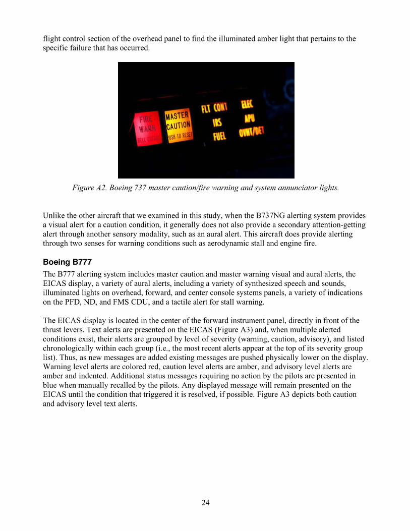
24
flight control section of the overhead panel to find the illuminated amber light that pertains to the specific failure that has occurred.
Figure A2. Boeing 737 master caution/fire warning and system annunciator lights.
Unlike the other aircraft that we examined in this study, when the B737NG alerting system provides a visual alert for a caution condition, it generally does not also provide a secondary attention-getting alert through another sensory modality, such as an aural alert. This aircraft does provide alerting through two senses for warning conditions such as aerodynamic stall and engine fire. Boeing B777 The B777 alerting system includes master caution and master warning visual and aural alerts, the EICAS display, a variety of aural alerts, including a variety of synthesized speech and sounds, illuminated lights on overhead, forward, and center console systems panels, a variety of indications on the PFD, ND, and FMS CDU, and a tactile alert for stall warning. The EICAS display is located in the center of the forward instrument panel, directly in front of the thrust levers. Text alerts are presented on the EICAS (Figure A3) and, when multiple alerted conditions exist, their alerts are grouped by level of severity (warning, caution, advisory), and listed chronologically within each group (i.e., the most recent alerts appear at the top of its severity group list). Thus, as new messages are added existing messages are pushed physically lower on the display. Warning level alerts are colored red, caution level alerts are amber, and advisory level alerts are amber and indented. Additional status messages requiring no action by the pilots are presented in blue when manually recalled by the pilots. Any displayed message will remain presented on the EICAS until the condition that triggered it is resolved, if possible. Figure A3 depicts both caution and advisory level text alerts.
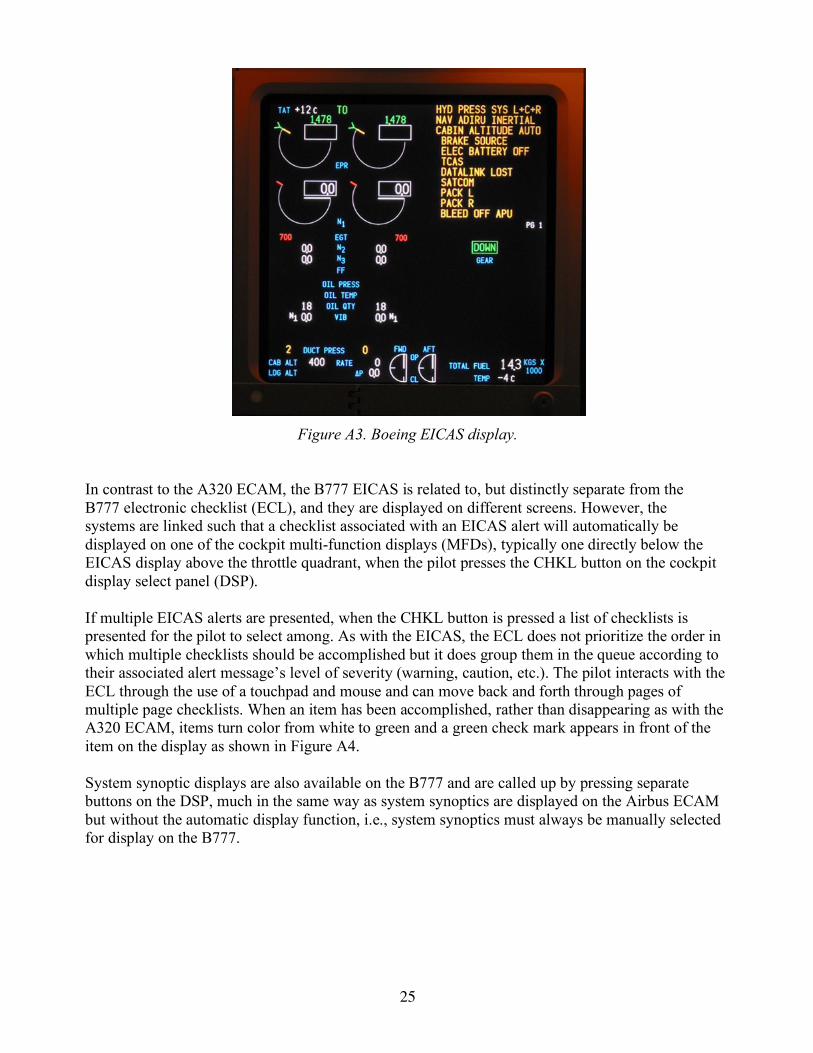
25
Figure A3. Boeing EICAS display.
In contrast to the A320 ECAM, the B777 EICAS is related to, but distinctly separate from the B777 electronic checklist (ECL), and they are displayed on different screens. However, the systems are linked such that a checklist associated with an EICAS alert will automatically be displayed on one of the cockpit multi-function displays (MFDs), typically one directly below the EICAS display above the throttle quadrant, when the pilot presses the CHKL button on the cockpit display select panel (DSP). If multiple EICAS alerts are presented, when the CHKL button is pressed a list of checklists is presented for the pilot to select among. As with the EICAS, the ECL does not prioritize the order in which multiple checklists should be accomplished but it does group them in the queue according to their associated alert message’s level of severity (warning, caution, etc.). The pilot interacts with the ECL through the use of a touchpad and mouse and can move back and forth through pages of multiple page checklists. When an item has been accomplished, rather than disappearing as with the A320 ECAM, items turn color from white to green and a green check mark appears in front of the item on the display as shown in Figure A4. System synoptic displays are also available on the B777 and are called up by pressing separate buttons on the DSP, much in the same way as system synoptics are displayed on the Airbus ECAM but without the automatic display function, i.e., system synoptics must always be manually selected for display on the B777.
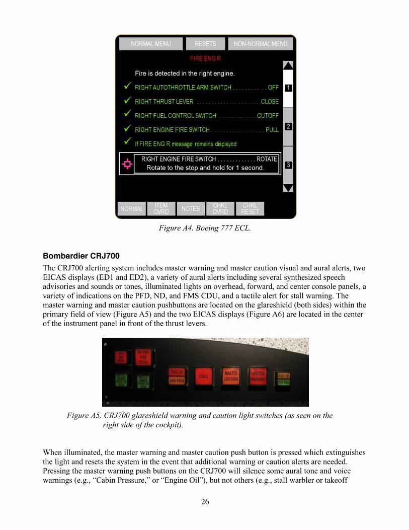
26
Figure A4. Boeing 777 ECL.
Bombardier CRJ700 The CRJ700 alerting system includes master warning and master caution visual and aural alerts, two EICAS displays (ED1 and ED2), a variety of aural alerts including several synthesized speech advisories and sounds or tones, illuminated lights on overhead, forward, and center console panels, a variety of indications on the PFD, ND, and FMS CDU, and a tactile alert for stall warning. The master warning and master caution pushbuttons are located on the glareshield (both sides) within the primary field of view (Figure A5) and the two EICAS displays (Figure A6) are located in the center of the instrument panel in front of the thrust levers.
Figure A5. CRJ700 glareshield warning and caution light switches (as seen on the
right side of the cockpit). When illuminated, the master warning and master caution push button is pressed which extinguishes the light and resets the system in the event that additional warning or caution alerts are needed. Pressing the master warning push buttons on the CRJ700 will silence some aural tone and voice warnings (e.g., “Cabin Pressure,” or “Engine Oil”), but not others (e.g., stall warbler or takeoff
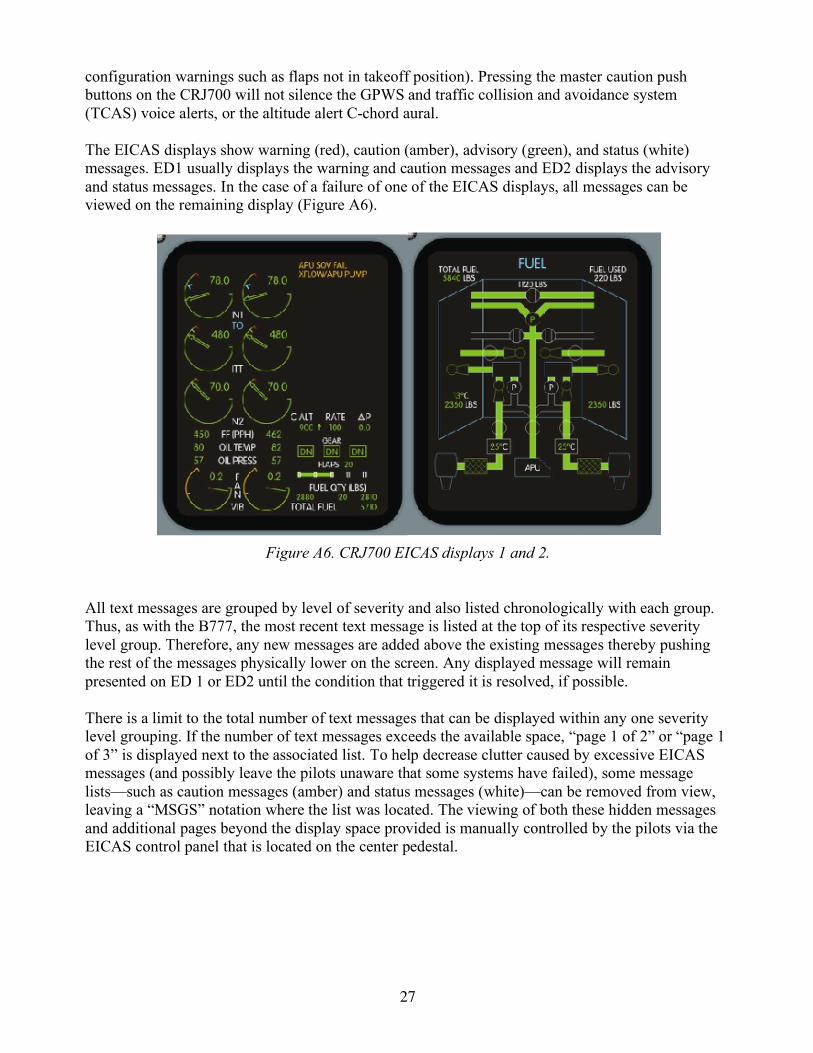
27
configuration warnings such as flaps not in takeoff position). Pressing the master caution push buttons on the CRJ700 will not silence the GPWS and traffic collision and avoidance system (TCAS) voice alerts, or the altitude alert C-chord aural. The EICAS displays show warning (red), caution (amber), advisory (green), and status (white) messages. ED1 usually displays the warning and caution messages and ED2 displays the advisory and status messages. In the case of a failure of one of the EICAS displays, all messages can be viewed on the remaining display (Figure A6).
Figure A6. CRJ700 EICAS displays 1 and 2.
All text messages are grouped by level of severity and also listed chronologically with each group. Thus, as with the B777, the most recent text message is listed at the top of its respective severity level group. Therefore, any new messages are added above the existing messages thereby pushing the rest of the messages physically lower on the screen. Any displayed message will remain presented on ED 1 or ED2 until the condition that triggered it is resolved, if possible. There is a limit to the total number of text messages that can be displayed within any one severity level grouping. If the number of text messages exceeds the available space, “page 1 of 2” or “page 1 of 3” is displayed next to the associated list. To help decrease clutter caused by excessive EICAS messages (and possibly leave the pilots unaware that some systems have failed), some message lists—such as caution messages (amber) and status messages (white)—can be removed from view, leaving a “MSGS” notation where the list was located. The viewing of both these hidden messages and additional pages beyond the display space provided is manually controlled by the pilots via the EICAS control panel that is located on the center pedestal.
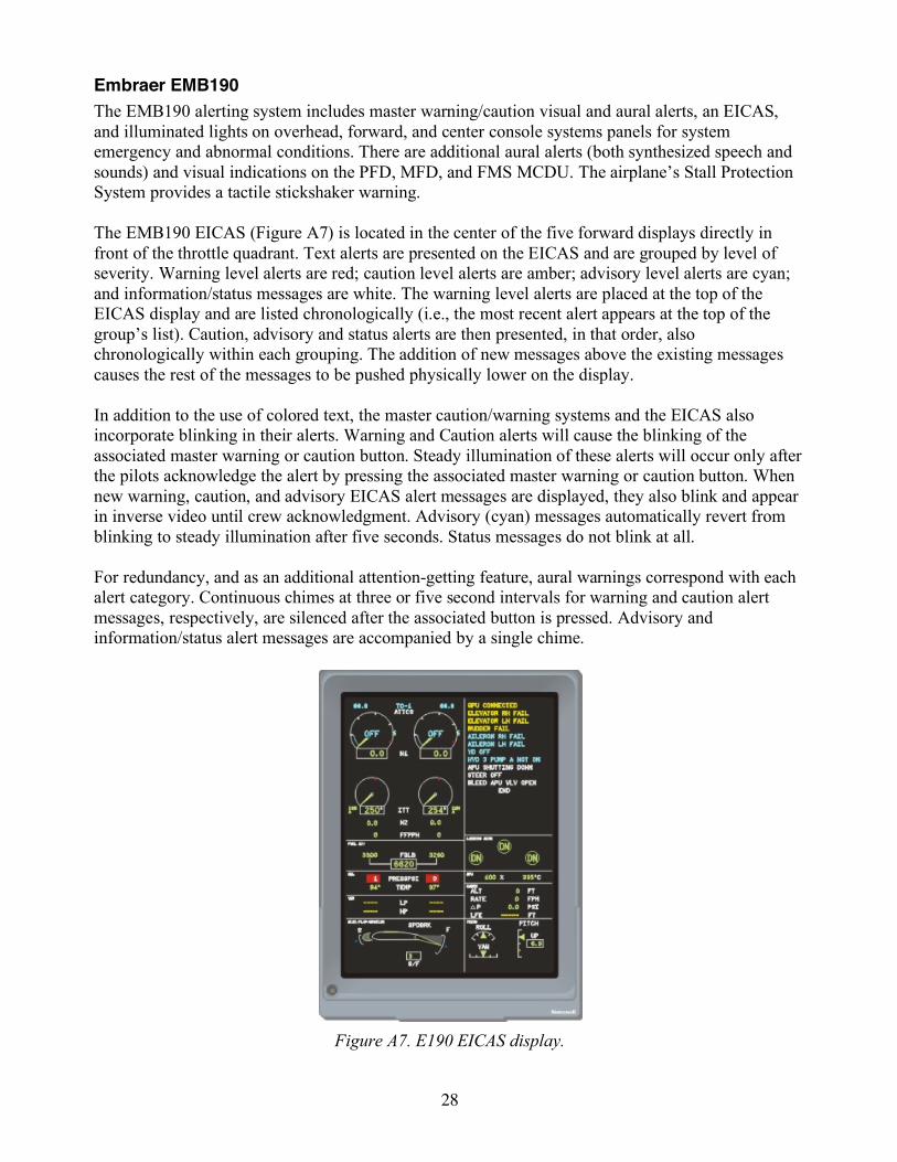
28
Embraer EMB190 The EMB190 alerting system includes master warning/caution visual and aural alerts, an EICAS, and illuminated lights on overhead, forward, and center console systems panels for system emergency and abnormal conditions. There are additional aural alerts (both synthesized speech and sounds) and visual indications on the PFD, MFD, and FMS MCDU. The airplane’s Stall Protection System provides a tactile stickshaker warning. The EMB190 EICAS (Figure A7) is located in the center of the five forward displays directly in front of the throttle quadrant. Text alerts are presented on the EICAS and are grouped by level of severity. Warning level alerts are red; caution level alerts are amber; advisory level alerts are cyan; and information/status messages are white. The warning level alerts are placed at the top of the EICAS display and are listed chronologically (i.e., the most recent alert appears at the top of the group’s list). Caution, advisory and status alerts are then presented, in that order, also chronologically within each grouping. The addition of new messages above the existing messages causes the rest of the messages to be pushed physically lower on the display. In addition to the use of colored text, the master caution/warning systems and the EICAS also incorporate blinking in their alerts. Warning and Caution alerts will cause the blinking of the associated master warning or caution button. Steady illumination of these alerts will occur only after the pilots acknowledge the alert by pressing the associated master warning or caution button. When new warning, caution, and advisory EICAS alert messages are displayed, they also blink and appear in inverse video until crew acknowledgment. Advisory (cyan) messages automatically revert from blinking to steady illumination after five seconds. Status messages do not blink at all. For redundancy, and as an additional attention-getting feature, aural warnings correspond with each alert category. Continuous chimes at three or five second intervals for warning and caution alert messages, respectively, are silenced after the associated button is pressed. Advisory and information/status alert messages are accompanied by a single chime.
Figure A7. E190 EICAS display.

29
Appendix B. Study Materials Subjected to Analysis
Table B1. Study Materials with Revision Dates
Aircraft Document Revision Revision Date B737NG Flight Manual 57 6/15/12 B737NG Quick Reference Handbood (QRH) 14 4/1/12 B737NG Flight Crew Training Manual (FCTM) 10 7/29/11 B737NG QRH 21 1/24/12 B737NG Operating Manual Volume 1 62 2/23/12 B737NG Operating Manual Volume l.2 21 4/7/09 B777 Flight Manual 26 10/28/11 B777 FCTM 10 6/30/12 B777 QRH 6/15/12 B777 Operating Manual Volume 2 30 6/27/12 B777 QRH 21 5/17/11 A320 Flight Crew Operating Manual (FCOM )Volume 1 9 10/15/12 A320 FCOM Volume 2 1 3/14/08 A320 QRH 8 6/1/12 A320 AOM Volume 2 9 6/2/09 A320 Training Manual 4/1/13 CRJ700 FCOM Volume 1 9 3/14/11 CRJ700 FCOM Volume 1 6 5/2/11 CRJ700 FCOM Volume 2 6 5/2/11
CRJ700 Pilot Advanced Qualification Program Manual – Standard Practice 9 11/8/12
CRJ700 CRJ700 QRH 9 11/9/12 CRJ700 FOM 2/2010 E190 FCOM Volume 1 13 6/1/2012 E190 FCOM Volume 2 6 2/23/11 E190 QRH 22 2/1/12 E190 Training Manual 4/1/13 E190 Normal Checklist (no date) E190 QRH 16 10/12/12

30
Appendix C. Airbus A320 Matrices > Click here to go to the Airbus A320 matrices Appendix D. Boeing 737NG Matrices > Click here to go to the Boeing 737NG matrices Appendix E. Boeing B777 Matrices > Click here to go to the Boeing B777 matrices Appendix F. Bombardier CRJ700 Matrices > Click here to go to the Bombardier CRJ700 matrices Appendix G. Embraer EMB190 Matrices > Click here to go to the Embraer EMB190 matrices