albrecht pmr taketalk
TRANSCRIPT

8/8/2019 Albrecht PMR Taketalk
http://slidepdf.com/reader/full/albrecht-pmr-taketalk 1/22
1
SERVICE MANUAL
2-WAY PORTABLE
HANDHELD PMR

8/8/2019 Albrecht PMR Taketalk
http://slidepdf.com/reader/full/albrecht-pmr-taketalk 2/22
HANDHELD PMR
2
CONTENTS 1. GENERAL
1.1 General
1.2 Characteristics and features
2. SPECIFICATION2.1 General Specification
2.2 Electrical Specification
3. OPERATION
3.1 Push buttons
3.2 ICONS on LCD
3.3 Key Functions3.4 Setting and Operation
4. ADJUSTMENT
4.1 Frequency synthesizer
4.2 Transmitter
4.3 Transmitter test
4 4 Receiver

8/8/2019 Albrecht PMR Taketalk
http://slidepdf.com/reader/full/albrecht-pmr-taketalk 3/22
3
batteries or
4 cells rechargeable NiMH batteries of the same size.
e) The radio is shipped with fixed (non-detachable) rubber duck antenna and belt
clip and carrying strip. It comes without batteries. Other equipment is optional.
2. SPECIFICATION
2.1 GENERAL SPECIFICATIONS
a) Frequency Range : 446.00625 ~ 446.09375 MHz
b) Output Impedance : 50Ω unbalanced
c) Modulation Type : 8K0F3E
d) Communication Mode : semi-duplex
e) Channel Capacity : 8 channels
f) Channel spacing : 12.5 kHz
g) Power : 6.0V(alkaline), 4.8 V (NiMH)
h) Battery Life : ALKALINE: at 1000mAh >30 hours (Tx5%, Rx5%, Stand-by 90%)
i) Operating Temperature : -20 degrees C to +60 degrees C
j) Dimension : 95.5(H)x 50(W)x 26(D)mm
k) Weight : 132 g (with Battery)
2 2 ELECTRICAL SPECIFICATION

8/8/2019 Albrecht PMR Taketalk
http://slidepdf.com/reader/full/albrecht-pmr-taketalk 4/22
4
9) Distortion : < 5% (1kHz 60% Modulation)
10) RX Audio Response : 6dB/OCT +/- 3dB DE-EMPHASIS (300Hz to 2.5kHz)
11) S/N Ratio : < 40dB (1kHz 60% modulation w/CCITT)
12) IF : 1'st IF = 21.7MHz
2'nd IF = 450kHz
13) Local Frequency :
1st Local Frequency = fc - 21.7MHz
2nd Local Frequency = 21.25MHz
3. OPERATION
3.1 Push Buttons and Controls

8/8/2019 Albrecht PMR Taketalk
http://slidepdf.com/reader/full/albrecht-pmr-taketalk 5/22
5
1) Battery Door
2) Monitor Button
3) Detachable Belt Clip
4) Push-To-Talk (PTT) Button
5) Antenna
6) External Mic / Speaker
7) Built-in Speaker
8) LCD Panel
9) Built-in Microphone
10) Up Button & Volume Control
11) Down Button & Volume Control12) Function Button
13) Power On/Off & Enter Button
3.2 ICONS on LCD

8/8/2019 Albrecht PMR Taketalk
http://slidepdf.com/reader/full/albrecht-pmr-taketalk 6/22
6
Appears in dual watch scan mode or when the dual watch scan mode isactivated.
6) Key Lock Indicator
Blinks in auto lock selection mode or when the key lock isactivated.
7) VOX Indicator
Blinks in VOX selection mode or appears when VOX is activated.
8) Battery Level Indicator
Battery Level Meter indicates the remaining battery strength.
9) Power Save Display

8/8/2019 Albrecht PMR Taketalk
http://slidepdf.com/reader/full/albrecht-pmr-taketalk 7/22
7
12) Large Segment Display
Indicates the channel number in use at the normal mode.When the Function Button is pressed, it displays the function menu
in sequence: CH / SC / dW / UO / Udt / ALo / CAL / ton
13) Small Segment Display
Displays the CTCSS tone option at the normal mode.CTCSS option is displayed in Hz.
Displays the SUBMENU of each MENU in the function mode.
(e.g. CH 1~69 / SC: up, dn / dW: channel number /
UO: high, off,low / Udt: 5sec, 3sec, 2sec, 1sec / ALo: off, auto / CAL number:1-7 / ton:no-Freq) 3.3 Key Function
3 3 K F ti
8/8/2019 Albrecht PMR Taketalk
http://slidepdf.com/reader/full/albrecht-pmr-taketalk 8/22
8
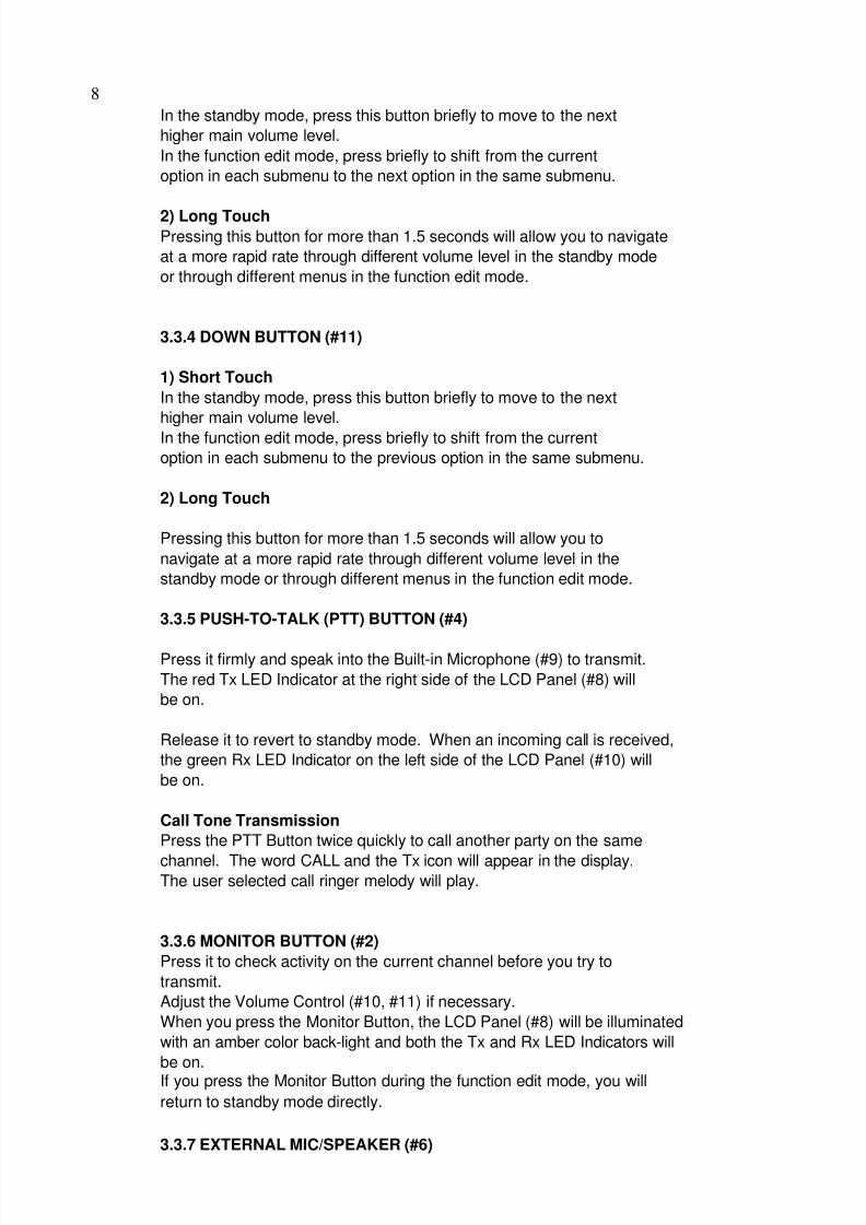
In the standby mode, press this button briefly to move to the next
higher main volume level.
In the function edit mode, press briefly to shift from the currentoption in each submenu to the next option in the same submenu.
2) Long Touch
Pressing this button for more than 1.5 seconds will allow you to navigate
at a more rapid rate through different volume level in the standby mode
or through different menus in the function edit mode.
3.3.4 DOWN BUTTON (#11)
1) Short Touch
In the standby mode, press this button briefly to move to the next
higher main volume level.
In the function edit mode, press briefly to shift from the current
option in each submenu to the previous option in the same submenu.
2) Long Touch
Pressing this button for more than 1.5 seconds will allow you to
navigate at a more rapid rate through different volume level in the
standby mode or through different menus in the function edit mode.

8/8/2019 Albrecht PMR Taketalk
http://slidepdf.com/reader/full/albrecht-pmr-taketalk 9/22
9
This jack accepts an optional headset/microphone for totally handsfree
operation.
Please refer to the user manual or Albrecht catalogue.See also section regarding VOX SELECTION MODE.
3.4 Setting and Operation
3.4.1 BASIC CHANNEL SELECTION
In order to communicate with other PMR units, both you and the receiving party
must be on the same channel. Tectalk has 8 channels (1-8) as indicated by
the large digits in the LCD Display Panel (#8).
Before, trying to transmit on the selected channel, you should press the Monitor
Button (#2) to check the activity on that channel.
If someone is already on the selected channel, you should try another
channel which is not occupied.
To change the basic channel, in the standby mode, press theUp Button (#10) briefly to move to the next higher main channel number.
Press the Down Button (#11) briefly to move to the next lower main channel
number.
3.4.2 CTCSS (Coded Tone Controlled Squelch System)
SUB-CHANNEL SELECTION MODE

8/8/2019 Albrecht PMR Taketalk
http://slidepdf.com/reader/full/albrecht-pmr-taketalk 10/22
10
To access the Auto Channel Scan menu, press the Function Button (#12) until the auto
channel icon blinks and SC appears in the LCD Panel (#8).
Press the Up Button (#10) or the Down Button (#11) to choose scanning up or down
from the current channel number.
Press the Enter Button (#13) to confirm your selection.
The unit will begin scanning for an active main channel. If a transmission is detected,
the Rx and RSSI icons will appear in the LCD Panel (#8).
To turn off the auto channel scan feature in the standby mode, simply press the
Function Button (#12) once.
3.4.4 DUAL WATCH SCAN MODE
This feature allows you to monitor two different channels at the same time. If you pre-
set any priority channel other than the current channel in use, the pre-set channel will bescanned every 0.5 second and signals you when a call is received.
To access the Dual Watch Scan menu,
Press the Function Button (#12) until the dual watch icon blinks and dW
appears in the LCD Panel (#8).
P th U B tt (#10) th D B tt (#11) t l t th d i d
8/8/2019 Albrecht PMR Taketalk
http://slidepdf.com/reader/full/albrecht-pmr-taketalk 11/22
11
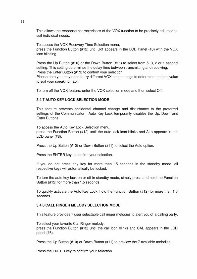
This allows the response characteristics of the VOX function to be precisely adjusted to
suit individual needs.
To access the VOX Recovery Time Selection menu,
press the Function Button (#12) until Udt appears in the LCD Panel (#8) with the VOX
icon blinking.
Press the Up Button (#10) or the Down Button (#11) to select from 5, 3, 2 or 1 second
setting. This setting determines the delay time between transmitting and receiving.Press the Enter Button (#13) to confirm your selection.
Please note you may need to try different VOX time settings to determine the best value
to suit your speaking habit.
To turn off the VOX feature, enter the VOX selection mode and then select Off.
3.4.7 AUTO KEY LOCK SELECTION MODE
This feature prevents accidental channel change and disturbance to the preferred
settings of the Communicator. Auto Key Lock temporarily disables the Up, Down and
Enter Buttons.
To access the Auto Key Lock Selection menu,
press the Function Button (#12) until the auto lock icon blinks and ALo appears in the
LCD l (#8)

8/8/2019 Albrecht PMR Taketalk
http://slidepdf.com/reader/full/albrecht-pmr-taketalk 12/22
12
4. SERVICE AND ADJUSTMENT
4.1 Frequency synthesizer (PLL)
a) Open the radio, disconnect the antenna and connect apower meter
And a 50 Ohms dummy load with the internal antenna connecting point of
TECtalk.
b) Check the voltage between TP & GND in digital volt meter.
c) Then set the low channel of TECtalk the lowest frequency.
d) After pressed PTT key of TECtalk , trim VC1 for adjusting the lowest
frequency of Tx channel to DC 1.5V in the voltage of TP1.
e) After releasing the PTT key, And then check if the highest frequency
of Rx channel is within DC 1.0V in the voltage of TP,
4.2 TRANSMITTER
a) Connect EUT & measure equipment according to block diagram below.
POWER SUPPLYMODULATION METER
OSCILLOSCOPE

8/8/2019 Albrecht PMR Taketalk
http://slidepdf.com/reader/full/albrecht-pmr-taketalk 13/22
13
a) Output Power Test
power(6.0V DC) should be Max.500mW and in -50% range.
b) Audio Response
Connect AF oscillator to Mic terminal and then firm the audio level
that doesn't distortion the wave of oscilloscope in the frequency range,
300Hz to 3kHz. Check the audio level for 300Hz to 3kHz based on frequency
standard, 1kHz.
c) Modulation Degree Test
1) Connect AF oscillator to the MIC terminal and then adjust the level
to 100mV
2) Measure the oscilloscope wave and he point needle of modulation meter
after pressing PTT key.
3) Sweep gradually the frequency of AF oscilloscope from 300Hz to 3kHz.
4) At this time, the point needle of modulation meter should be in
the limit of +/- 2.5 kHz.
d) Spectrum Test
1) terminate antenna output with 50 Ohms and use a power attenuator of 20 dB, to avoid

8/8/2019 Albrecht PMR Taketalk
http://slidepdf.com/reader/full/albrecht-pmr-taketalk 14/22
14
c) Signal generator Adjustment for RX sensitivity test
1) Adjust SSG to channel frequency.
2) Adjust modulation frequency, 1kHz to modulation degree, 1.5 kHz.
3) After adjusting the frequency of SSG to channel frequency, set RF level
to -47dBm.
d) Check and adjust Squelch sensitivity
1) Set the standard channel.
2) In squelch mode, SQ volume RV1 must be turned counterclockwise to open the
squelch.
3) After adjusting SSG to channel frequency, the RF level of SSG is set
so that a SINAD of 8 6dB is obtained. Turn potentiometer carefully so that
Squelch just opens at that point.
4.5 RECEIVER TEST
) R iti it t t

8/8/2019 Albrecht PMR Taketalk
http://slidepdf.com/reader/full/albrecht-pmr-taketalk 15/22
15
b) Troubleshooting
a)Transmitter
Power key is on condition but does not work.
Battery could completely be discharged.
Battery cell wrong inserted?
Contact problem between Battery and Radio?
Fail to transmit
Run out of battery or charge problem.
Fault of PTT key
Fault of Q4, Q5.
Transmitter works but frequency is unmatched
defective frequency synthesizer.
defective X-tal (X2).
No audio modulation (Tx power and Tx frequency are normal)
Problem of microphone or mic connector.
IC U7 problem.
Tx is set when switch is on.
T i h bl

8/8/2019 Albrecht PMR Taketalk
http://slidepdf.com/reader/full/albrecht-pmr-taketalk 16/22
16
5. DESCRIPTION OF RADIO CIRCUIT
5.1 Frequency synthesizer
Frequency synthesizer consists of VCO, PLL IC(built in PRESCALER) and
loop filter.
a) VCO
VCO is composed of ONE VCO. Oscillation circuit takes colpitts circuit using
variable Diode. And VCO is composed of D1,Q8,Q9,C81,C75,VC1,L1,C74,C76.
VCO control voltage through loop filter adjusts frequency and microphone
signal through modulation terminal generates FM modulation.
b) PLL IC
PLL IC is adjustable IC to produce the desired frequency which VCO
provides through loop filter. It has internal counter using 21.25MHz
reference frequency to generate 6.25kHz as reference Signal. VCO frequency
from prescaled input is divided signal and compared with reference
signal phase in phase comparator. Built-in charger pump changes voltage
(until two signals are in phase) and charged voltage supplies VCO
through loop filter to produce the desired frequency.
Frequency data associated with channel goes to PLL IC by CPU
th h CLOCK DATA PLL IC bl b t b li f CPU

8/8/2019 Albrecht PMR Taketalk
http://slidepdf.com/reader/full/albrecht-pmr-taketalk 17/22
17
b) Front End
Front-End has Q1 to provide a high sensitivity and low noise feature.
It employs SAW filter as band pass filter to eliminate image frequency
frequency and to produce enough pass band by Q1 input and output.
c) Mixer
Mixer has one base BFQ 67W(Q2) to feature high low noise quality.
It has RF signal through L7, L8, SF1,SF2 and Q1 RF signal from Local
oscillator mixed.
It develops 1'st IF ,21.7MHz. 1st IF goes to 1st IF amplifier Q3(KTC4080)
base through X-tal filter XF1.
IF of mixing signals is selected and enters the X-tal filter.
Output impedance of mixer is direct matched with input impedance
of X-tal filter.
Matching of filter satisfies pass bandwidth of filter, ripple
elimination within the pass band, and attenuation characteristic of stop
band. X-tal filter is composed of two pole monolithic X-tal filter,
with 8kHz of IF bandwidth. R11 is used as impedance matching with 1'st IF
Amp Q3.

8/8/2019 Albrecht PMR Taketalk
http://slidepdf.com/reader/full/albrecht-pmr-taketalk 18/22
18
When Tx starts with pressing PTT switch, VCO output amplifies through
Q4,Q5 transmits by antenna through low pass filter.
Tx RF signal produced from Tx VCO is amplified by DRIVER Q5 through C53
and entered Q4 POWER TR input terminal with final amplification.
After this stage, the signal is emitted at antenna through 50 Ohms matching
circuit to low pass filter(L7,L6,L5,C42,C43,C44,C46,C47) to eliminate
harmonics.
5.3.1 Audio Modulation and Audio Amplification
Audio signal produced by external or internal microphone is amplified and limitted
by IC U7. The output signal enters to VCO through low pass filter and
U2. Max. Frequency modulation deviation is adjusted by VR1
Audio modulation and audio amplification has preemphasis characteristic of 6dB/OCT
by U7(NJM324V).
11. CHANNEL DATA
8/8/2019 Albrecht PMR Taketalk
http://slidepdf.com/reader/full/albrecht-pmr-taketalk 19/22
19
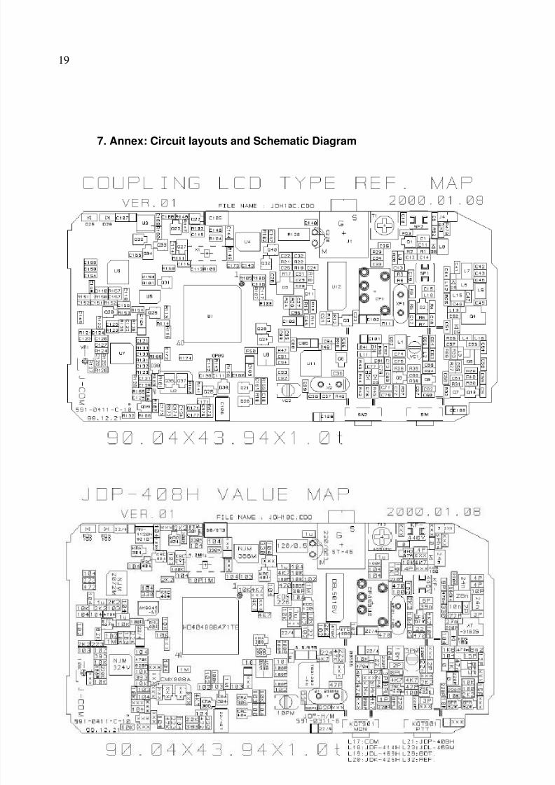
7. Annex: Circuit layouts and Schematic Diagram

8/8/2019 Albrecht PMR Taketalk
http://slidepdf.com/reader/full/albrecht-pmr-taketalk 20/22
20

8/8/2019 Albrecht PMR Taketalk
http://slidepdf.com/reader/full/albrecht-pmr-taketalk 21/22
21

8/8/2019 Albrecht PMR Taketalk
http://slidepdf.com/reader/full/albrecht-pmr-taketalk 22/22
1