alarms_102_ppt
TRANSCRIPT
Alarms 102
Fire Alarm Systems TrainingFire Alarm Systems Training
Presented By:Paul J. Inferrera, SET
Cape Fear Community College

Cells Phones / PagersPlease set cell phones, PDA’s and pagers to off or silent operation. If you need to accept a call, please do so quietly and leave the room to conduct your conversation
BreaksDue to the short duration of this seminar their will not be a scheduled break. You may excuse yourself at anytime but please do so quietly
QuestionsYou may ask questions at any time, but please wait to be recognized and respect whoever has the floor.
Housekeeping
www.cfcc.edu2

www.cfcc.edu3
About the Presenter
Lead Instructor, Cape Fear Community College• Fire Alarm Systems Training Program
NICET Ambassador• Fire Alarm Systems IV• Special Hazard Suppression Systems I
ASCET Communications Manager
Over 29 years of combined experience in the FireProtection industry.

www.cfcc.edu4
Program OverviewFire Alarm Systems Training
Fire Alarm Systems Training at Cape Fear Community
College is a program to produce competent and qualified
individuals. It is our belief that properly trained and
knowledgeable fire alarm system designers and technicians
will reduce the amount of false alarms and improve the
quality of life in their community.

Codes and Standards referenced are consistent withNICET’s allowable references for level I and II FireAlarm Systems exams
NFPA 70 (2008)
NFPA 72 (2007)
Consult with your Authority Having Jurisdiction (AHJ),or Project Specifications for the edition(s) enforced
www.cfcc.edu5
Codes and Standards

Learning Objectives
Understand the requirements of prescriptive andperformance-based designDiscuss listing agencies and their requirements forlisting and device compatibilityReview methods of secondary power and voltagedrop calculationsLearn the basics of smoke propagation and theparticles of combustionKnow causes of unwanted alarms and ways toeliminate or prevent nuisance alarmsUnderstand contracts and constructionrelationships.
www.cfcc.edu6

www.cfcc.edu7
Prescriptive and Performance-Based Design

Prescriptive vs Performance
www.cfcc.edu8
Prescriptive DesignThis is a design approach which relies on the requirements directly from the applicable codes
Fire Alarm System Designers practice prescriptive design
Performance-Based DesignThis is a design approach which is used when the prescriptive requirements listed in the applicable codes are inadequate
Performance-based design should be done by a fire protection engineer.

Prescriptive vs Performance
www.cfcc.edu9
Hazard AnalysisDefine the Fire Protection Goal
Life Safety
• Detect the effects of a fire prior to deadly levels
Property Protection
• Areas or facilities not expected to have occupants
Mission Protection
• Limited impact on facility performance.

www.cfcc.edu10
Codes and Standards
Codes and StandardsCodes and standards govern products, construction,manufacturing, communication protocols and every aspect of ourlives. A uniform and agreed upon way of doing things enablessuch milestones in human existence like the production line andthe calendar.
Earliest building code is thought to have been developedsometime between 1955 B.C. and 1913 B.C.
Reign King Hammurabi of Babylon or “Hammurabi’s Code”
Code didn't specify how to build a building, but laid out theconsequences of not building well
Fire alarm systems are required by code and installed perstandards.
www.cfcc.edu11
Codes and Standards
www.cfcc.edu12
CodesA code is a model or a set of rules that are recommended for others to follow Not a law, but can be adopted into law
StandardsA published document that contains a technical specification or other precise criteria designed to be used consistently as a rule, guideline, or definition An agreed, repeatable way of doing something Laws and regulations may refer to certain standards and make
compliance with them compulsory.

www.cfcc.edu13
Listing Agencies

Listing AgenciesNationally Recognized Testing Laboratory (NTRL) is a program,which is a part of OSHA's Directorate of Technical Support andEmergency Management
The Program recognizes private sector organizations asNRTL’s
Recognition signifies that an organization has met thenecessary qualifications specified in the regulations for theProgram
Determines that specific equipment and materials(products) meet consensus-based standards of safety toprovide the assurance, required by OSHA, that theseproducts are safe for use in the U.S. workplace.
www.cfcc.edu14

Listing AgenciesTest Methods
Smoke detectors operating on different principles of operation respond differently to smoke from different combustibles. All smoke detectors required to pass tests to become
listed UL has established different test fires Every detector must detect these five types of test fires
1. N-heptane 2. Polystyrene (black)3. Wood (gray)4. Newspaper (gray)5. Wood pyrolized on a hot plate (smoldering, gray).
www.cfcc.edu15

www.cfcc.edu16
Device and System Compatibility
Device and System CompatibilityUL-985: Household Fire Control Units
These requirements cover household fire warning system control units
Intended to be installed in accordance with the National Fire Alarm Code, NFPA 72
National Electrical Code, NFPA 70.
www.cfcc.edu17

Device and System CompatibilityUL-268: Smoke Detectors for Signaling Systems
This Standard sets forth requirements for smoke detectors and mechanical guards to be employed in ordinary indoor locations in accordance with the following
In the United States• National Fire Alarm Code, NFPA 72
In Canada• Standard for the Installation of Fire Alarm Systems,
CAN/ULC-S524• National Building Code of Canada• National Fire Code of Canada.
www.cfcc.edu18

Device and System CompatibilityCompatibility and Listing
Listed
Equipment, materials or services included in a list published by an organization that is acceptable to the authority having jurisdiction
Evaluation of products or services, that maintains periodic inspection of production of listed equipment or materials or periodic evaluation of services
Listing states that either the equipment, material, or service meets appropriate designated standards or has been tested and found suitable for a specified purpose.
www.cfcc.edu19

Device and System CompatibilityCompatibility and Listing
Compatible
All fire detection devices that receive their power from the initiating device circuit or signaling line circuit of a fire alarm control unit shat be listed for use with that control unit
Compatibility Listed
A specific listing process that applies only to two-wire devices, such as smoke detectors, that are designed to operate with certain control equipment.
www.cfcc.edu20

Device and System CompatibilitySmoke Detectors
Conventional Detector Operation
Connects to IDC using dry contacts
• Requires separate power source
• Often called 4-wire detectors
Receives operating power from IDC
• Must be compatible with control panel
• Often called 2-wire detectors
• Compatibility listing by manufacturer.
www.cfcc.edu21

Device and System CompatibilityNotification Appliances
In general, do not require compatibility listing
Power source must match voltage requirements
When compatibility listing is required
• Addressable notification appliances
• Special Applications.
www.cfcc.edu22
Device and System CompatibilityDoor Holders
General
Where smoke door release is accomplished directly from the smoke detector(s), the detector(s) shall be listed for releasing service
Magnetic door holders that allow doors to close upon loss of operating power shall not be required to have a secondary power source.
www.cfcc.edu23

Device and System CompatibilityRelays
General
Equipment constructed and installed in conformity shall be listed for the purpose for which it is used.
www.cfcc.edu24
System Calculations
www.cfcc.edu25

System CalculationsNFPA 72, the National Fire Alarm Code specifies thatcalculations be made prior to the installation of a new fire alarmsystem
Submittal procedures when planning a new systemrequires• Battery• Voltage drop calculations.
www.cfcc.edu26

System CalculationsCalculations
Standby power requires several pieces of information we need todetermine in order to calculate the proper stand-by battery size.
Standby Time in normal operation
Standby Time in alarm operation
De-rating factor
Standby Load
Alarm Load.
www.cfcc.edu27

System CalculationsCalculations
Standby Time in normal operation• Specified in NFPA 72 most require 24-hours
Standby Time in alarm operation• Specified in NFPA 72 most require 5-minutes
De-rating factor• Industry standard is 20% of the amp-hour rating
Standby Load• Load (amps) x Time (hours) = Amp-Hour (AH)
Alarm Load• Alarm Load (amps) x Standby Time (hours) = AH.
www.cfcc.edu28

System CalculationsCalculations
We add the standby load to the alarm load for our totalstandby power
Take into consideration of the batteries de-rating factor andmultiply the amp-hours required by 1.2 which represent anadditional 20%
Our standby batteries must be larger than the resulting AHand you will have to select the proper size available from themanufacturer.
www.cfcc.edu29
System CalculationsVoltage Drop
The NEC generally doesn't require you to size conductors toaccommodate voltage drop. It merely suggests in the notes toadjust for voltage drop when sizing conductors.
National Fire Alarm Code does since that code dictateshow the system will operate
Voltage drop is extremely critical to the proper operationof all electrical devices attached to a fire alarm system
Notification Appliance Circuits or NACs that connect toa fire alarm control panel (FACP) are most affected bydrops in voltage.
www.cfcc.edu30
System CalculationsVoltage Drop
The voltage drop of a circuit is in direct proportion to theresistance of the conductor and the magnitude of the current.
If you increase the length of a conductor, you increase itsresistance — and thus increase its voltage drop
If you increase the current, you increase the conductorvoltage drop
This is basic Ohm’s Law and long runs often producevoltage drops that exceed NEC and NFPArecommendations.
www.cfcc.edu31

System CalculationsVoltage Drop
The following information is needed to determine circuit voltagedrop
Conductor Size - Determined by the system designer Conductor Length - Obtained from drawings submitted Conductor Resistance - Found in tables in the NEC Total Current - Found using Ohm’s Law Total Voltage - Found using Ohm’s Law Voltage Required at Device - This information is found in
published equipment datasheets provided by themanufacturer.
www.cfcc.edu32

www.cfcc.edu33
Combustion: Theory and Principles

Combustion: Theory and Principles
www.cfcc.edu34
Fire SignaturesA Fire Signature is a Detectable Product of Combustion
Smoke• Aerosol or airborne particles
Heat• Could be hours for slow burning or smoldering
fires Toxic Gases
• Produced by all fires influenced by fuel Radiant Energy
• Infrared and ultraviolet energy emitted from combustion.

Combustion: Theory and Principles
www.cfcc.edu35
Thermal Particulate PointHeated materials release sub-micrometer size particles
Particles agglomerate and form larger particles
Visible particles can be produced during pre-ignition heating
• Usually several hundred degrees greater than thermal particulate point
Smoldering fires produce larger particles more than any other stage of the fire
Majority of particles are smaller than 0.3 micrometers.

Combustion: Theory and Principles
www.cfcc.edu36
Material Temperature (˚F) Temperature (˚C)
PVC Insulation 290 142
Motor Oil (SAE30) 310 153
Pine Board 320 158
Acrylan Carpet 340 169
Wool 360 180
Bakelite 380 191
Polyethylene 410 208
Paper 500 257
Polystyrene 710 373

Combustion: Theory and Principles
www.cfcc.edu37
Fire SignaturesSmoke
Aerosol or airborne particles
5 x 10⁴ to 10 micrometers in size
Brownian Motion
Visible or invisible
Visible particles add color
Visible particles scatter light.

Combustion: Theory and Principles
www.cfcc.edu38
Fire SignaturesHeat
Released during all fires
Signature not detectable until deadly
Detectors for this signature not considered a life safety device.
Combustion: Theory and Principles
www.cfcc.edu39
Toxic Gases
Carbon Monoxide (CO)• Responsible for more fatalities
Carbon Dioxide (CO2)• Intoxication effect on people
Hydrogen Chloride (HCL)• Produced by burning plastics
Fires produce other detectable gases while consuming oxygen Atmospheric content of 21% oxygen is normal.

Combustion: Theory and Principles
www.cfcc.edu40
Flame Signatures
Infrared (IR)• Measures signature from carbon dioxide and water
vapor Flame flicker (Hz)
• Quite specific, frequency range is 5-30Hz Ultraviolet (UV)
• Emissions from hydroxyl, carbon dioxide and carbon monoxide.
Combustion: Theory and Principles
www.cfcc.edu41
Heat Release Rate
Rate at which heat is released by a fire
Expressed in terms• Kilowatts/second• Btu/second (British Thermal Unit)
NFPA 72 table list typical release rates of fuels.

Combustion: Theory and Principles
www.cfcc.edu42
Fire Growth Rate
Time it takes a fire to reach a heat release rate of 1,055 KW/sec
Fires classified by growth rates
• Slow – 400 seconds or more
• Medium – 150 seconds up to 400 seconds
• Fast – less than 150 seconds
Table B.2.3.2.3.6 in NFPA 72 (2007), Appendix B.

Combustion: Theory and Principles
www.cfcc.edu43
Heat and Growth Rates
Detector Time Constant
Research conducted by FM Global
Time it takes for heat detector to get as hot as surrounding air
Described as thermal lag
Table B.3.2.5 in NFPA 72 (2007), Appendix B.
www.cfcc.edu44
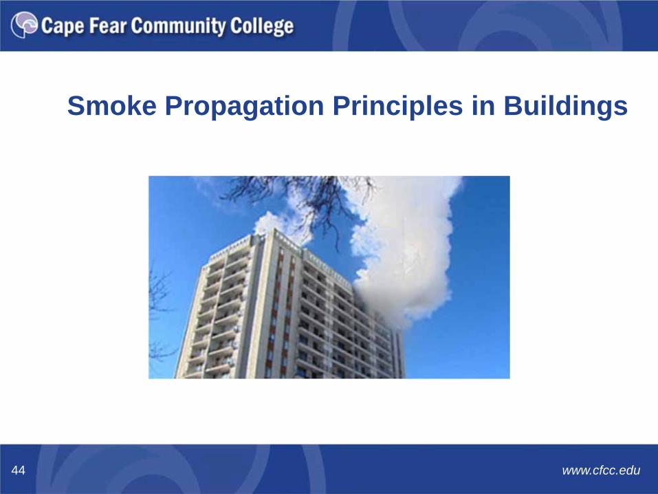
Smoke Propagation Principles in Buildings

Aerosol – a suspension of fine solid particles or liquid droplets in a gas
Combustion – the sequence of exothermic chemical reactions between a fuel and an oxidant
Pyrolysis – a form of incineration that chemically decomposes organic materials by heat in the absence of oxygen
Smoke – the airborne solid, liquid particulates and gases evolve when a material undergoes pyrolysis or combustion, along with the quantity of air that is entrained or otherwise mixed into the mass
Stack Effect – the vertical natural air movement through the building caused by the differences in temperatures, and densities between the inside and outside air.
Smoke Propagation
www.cfcc.edu45
What is Smoke?The term “smoke” is defined as the aerosol or condensed phasecomponent of the products of combustion.
Solid and liquid particulates Entrained air
Characteristics
Smoldering combustion – light colored droplets Flaming combustion – black, solid, soot Size of particles.
Smoke Propagation
www.cfcc.edu46

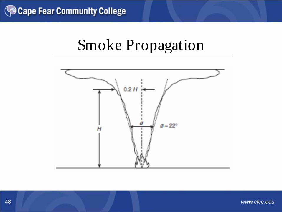
Characteristics Smoke plumes retain heat from fire Volume of plume is mostly air Fuel determines the composition of smoke Highest temperature in center of plume Temperature determines buoyancy Formulas developed to predict amount of smoke
But…Actual results from a real fire are virtually unpredictable, andreal world results will vary drastically from the mathematical model.
Smoke Propagation
www.cfcc.edu47
Smoke Propagation
www.cfcc.edu48

Smoke Movement Temperature inside is
greater than outside Effect is increased as
building height increases Considered “normal” stack
effect Air pulled into building at
bottom Air forced out at top.
Cool Air
Hot Air
Smoke Propagation
www.cfcc.edu49

Smoke Movement Temperature outside is
greater than inside Effect is increased as
building height increases Cooler air falls Air pulled into building at
top Air forced out at bottom.
Hot Air
Cool Air
Smoke Propagation
www.cfcc.edu50

Smoke Movement Air drafts upward toward
areas of low pressure Effect is increased as
building height increases Neutral plane exists between
pressure and updraft Air pulled into building at
bottom Air escapes out at top.
Wind SideLeeward
Side
NEUTRAL
PLANE
Smoke Propagation
www.cfcc.edu51

Building Design Essential design features to protect life and property
• Alarms• Suppression System• Fireproof Compartments
Building codes allow reduction or elimination of ratings• Code trade-offs offset cost of sprinkler installation• Eliminating any one of three fire protection elements
compromise integrity of building NFAPA 101 and 105 provide information on
construction of smoke barriers.
Smoke Propagation
www.cfcc.edu52

Floors and Partitions Impede the free movement of air Conditions that contribute to air movement
• Buildings’ function and construction• Vertical shafts (stairwells and elevators)• Floor to floor openings
Air movement between floors caused by pressuredifferentials• Air moves from areas of high to low pressure.
Smoke Propagation
www.cfcc.edu53

Dilution Also referred as smoke purging. Can be effective if
• Amount of leakage is small• Rate of purging air is greater than amount of leakage• Can be beneficial to firefighters after fire is
extinguished HVAC system provides no significant improvement
• Fires produce large quantities of smoke• Purging systems should not be used within fire
compartment.
Smoke Propagation
www.cfcc.edu54

Pressurization Also called smoke control systems
• Stairwells• Zoned smoke control
Designed to provide a path of egress for occupants Elevator smoke control is rarely used unless they are
means of egress.
Smoke Propagation
www.cfcc.edu55

Pressurization Three design concerns for pressurized stairwells
• Pressure differences from height• Pressure fluctuations from use• Location of supply duct and fans
Design concepts• Over pressure relief• Feedback control
Most severe pressure fluctuations result from openingground floor exterior door.
Smoke Propagation
www.cfcc.edu56
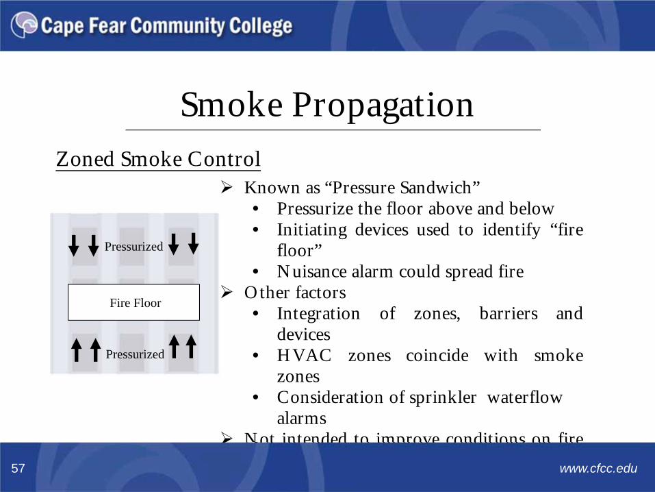
Zoned Smoke Control Known as “Pressure Sandwich”
• Pressurize the floor above and below• Initiating devices used to identify “fire
floor”• Nuisance alarm could spread fire
Other factors• Integration of zones, barriers and
devices• HVAC zones coincide with smoke
zones• Consideration of sprinkler waterflow
alarms Not intended to improve conditions on fire
floor.
Pressurized
Pressurized
Fire Floor
Smoke Propagation
www.cfcc.edu57
Buoyancy Utilizes the natural movement of smoke
• Shopping Malls• Arenas• Exhibition Halls
Generally ceiling heights in excess of 33 feet• Allows the space to fill with smoke• Systems exhaust smoke from top• Provides time for occupants to escape• Smoke will eventually fill the space.
Smoke Propagation
www.cfcc.edu58

Automatic Detection Methods
www.cfcc.edu59

Fire SignatureA fire produces elements that can be detected
Heat Smoke (aerosol particulate) Gas Light radiation
Challenges of Detection
Not all fires produce all elements Ambient conditions may mimic elements.
Automatic Detection Methods
www.cfcc.edu60

Classified by NFPA 72Groups
Heat or Thermal – high temperature and/or rate of rise Smoke – aerosol particles Fire-Gas Sensing – detects gases produced by fire Radiant Energy – detects ultraviolet, infrared or visible
light radiationTypes
Line type Spot Type Air Sampling.
Automatic Detection Methods
www.cfcc.edu61

CombinationRespond to fire elements either
Respond to more than one fire element• Smoke detector with thermal element
More than one operating principle for one element• Rate of rise and fixed temperature
Detectors either Send data to control panel for processing Makes decision and signals control panel.
Automatic Detection Methods
www.cfcc.edu62

Radiant Energy Capable of fast detection Commonly used in high hazard areas Spacing by manufacture’s recommendations Line of sight devices
Types Infrared (IR) Ultraviolet (UV) Combination (UV/IR).
Automatic Detection Methods
www.cfcc.edu63

www.cfcc.edu64
Smoke Sensing Detectors
Characteristics
Provide faster response than heat detectors Actuate prior to deadly effects of fire Considered a life safety device Listed spacing is not reduced
Types Ionization Photoelectric Projected beam Air sampling.
Smoke Detectors
www.cfcc.edu65

TypesIonization
Radioactive material ionizes air in sensing chamberPhotoelectric
Light source is scattered by smoke in sensing chamberProjected Beam
Intensity of beam is reduced at receiverAir Sampling
Aspiration system induces atmosphere to sensingchamber.
Smoke Detectors
www.cfcc.edu66

www.cfcc.edu67
Heat Sensing Detectors
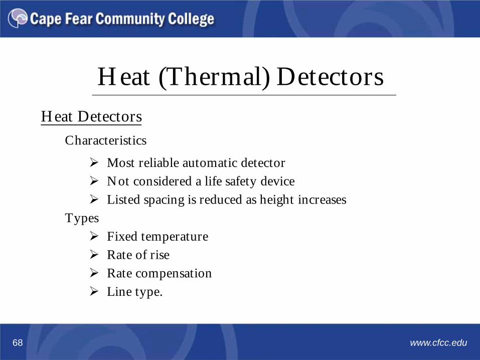
Heat DetectorsCharacteristics
Most reliable automatic detector Not considered a life safety device Listed spacing is reduced as height increases
Types Fixed temperature Rate of rise Rate compensation Line type.
Heat (Thermal) Detectors
www.cfcc.edu68

TypesFixed Temperature
Initiates alarm when temperature is reachedRate of Rise
Initiates alarm when temperature rises in a short timeLine Type
Initiates alarm when cable is shorted Initiates alarm upon increase in current flow Initiates alarm upon loss of pressure
Rate Compensation Initiates alarm when ambient temperature is reached.
Heat (Thermal) Detectors
www.cfcc.edu69

Operating ModesRestorable
Not normally destroyed Restoration may be manual or automatic
Non-Restorable
Element designed to be destroyed.
Heat Detectors
www.cfcc.edu70
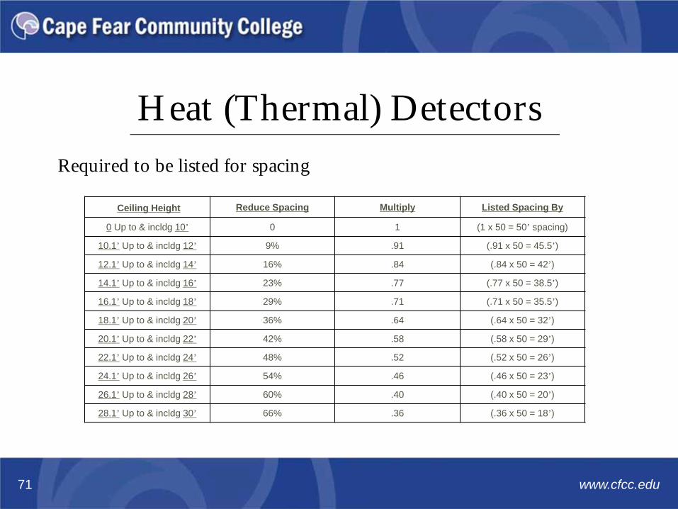
Required to be listed for spacing
Ceiling Height Reduce Spacing Multiply Listed Spacing By
0 Up to & incldg 10’ 0 1 (1 x 50 = 50’ spacing)
10.1’ Up to & incldg 12’ 9% .91 (.91 x 50 = 45.5’)
12.1’ Up to & incldg 14’ 16% .84 (.84 x 50 = 42’)
14.1’ Up to & incldg 16’ 23% .77 (.77 x 50 = 38.5’)
16.1’ Up to & incldg 18’ 29% .71 (.71 x 50 = 35.5’)
18.1’ Up to & incldg 20’ 36% .64 (.64 x 50 = 32’)
20.1’ Up to & incldg 22’ 42% .58 (.58 x 50 = 29’)
22.1’ Up to & incldg 24’ 48% .52 (.52 x 50 = 26’)
24.1’ Up to & incldg 26’ 54% .46 (.46 x 50 = 23’)
26.1’ Up to & incldg 28’ 60% .40 (.40 x 50 = 20’)
28.1’ Up to & incldg 30’ 66% .36 (.36 x 50 = 18’)
Heat (Thermal) Detectors
www.cfcc.edu71

Prevention of Nuisance and False Alarms
www.cfcc.edu72

Prevention of Nuisance and False Alarms
The National Fire Protection Association collects false alarm datafrom fire departments and state authorities that participate in theNational Fire Incident Reporting System (NFIRS)
Development of automatic detection systems, and lesser use ofpublic call boxes
• False alarm trends by malicious activation dropped
• System malfunction false alarms increased
Methods and procedures to reduce false alarms but are not asubstitute for proper selection of devices or technologies.
www.cfcc.edu73

Prevention of Nuisance and False Alarms
Follow the Codes!The most important thing to remember when it comes to theavoidance of nuisance alarms is: FOLLOW THE CODES!
The codes are developed for several reasons, one of whichis the avoidance of nuisance alarms• Ensure the system has proper power available• Locate smoke and heat detectors only in appropriate
environments• Locate other detection devices according to the
manufacture’s instructions.
www.cfcc.edu74
Prevention of Nuisance and False Alarms
Smoke and Heat Detector Location
Automatic and heat detectors shall be located at least 4” out ofcorners
Sidewall mounted detectors shall be mounted such that someportion of the detectors is within 12” on the ceiling
Detectors shall first be located within ½ spacing of thesidewall. Then listed spacing between detectors.
www.cfcc.edu75

Prevention of Nuisance and False Alarms
Smoke Detector Location
Shall be located in appropriated environments Environment temperature is not less than 32 degrees and no
greater than 100 degrees Fahrenheit Environment relative humidity does not exceed 93% Environment air velocity does not exceed 300 ft/min Shall not be installed until AFTER construction clean-up!
www.cfcc.edu76

Prevention of Nuisance and False Alarms
Heat Detector Location
Shall be rated 20 degrees higher than expected temperature atceiling
Not considered life safety devices Most reliable automatic fire detector Ceiling height increases, spacing decreases When used in sprinkled hoist ways to shunt power, they shall
be rated at lower temperature than sprinkler head.
www.cfcc.edu77

www.cfcc.edu78
Construction Relationships and Contracts

Construction Relationships and Contracts
www.cfcc.edu79
A variety of factors make a construction contract different frommost other types of contracts. These include the length of theproject, its complexity, its size and the fact that the price agreedand the amount of work done may change as it proceeds.Often, in the context of a construction contract, there are threeprimary parties
The owner of the project The architect, who is responsible for drawing up the
various plans and blueprints The general contractor, who is responsible for
overseeing and supervising the project’s actualconstruction.

Construction Relationships and Contracts
www.cfcc.edu80
What's In A Contract?It is very important for a contract to clearly spell out what is expected of each party. Compensation, and at how and when does payment
occur? How and when can the contract be terminated? What are the basic services covered? How are extra services (for extra fee) incurred? Who has what rights to the plans or other product? Will the architect or engineer modify plans and specs to
bring the project within budget without charge to the owner?
Construction Relationships and Contracts
www.cfcc.edu81
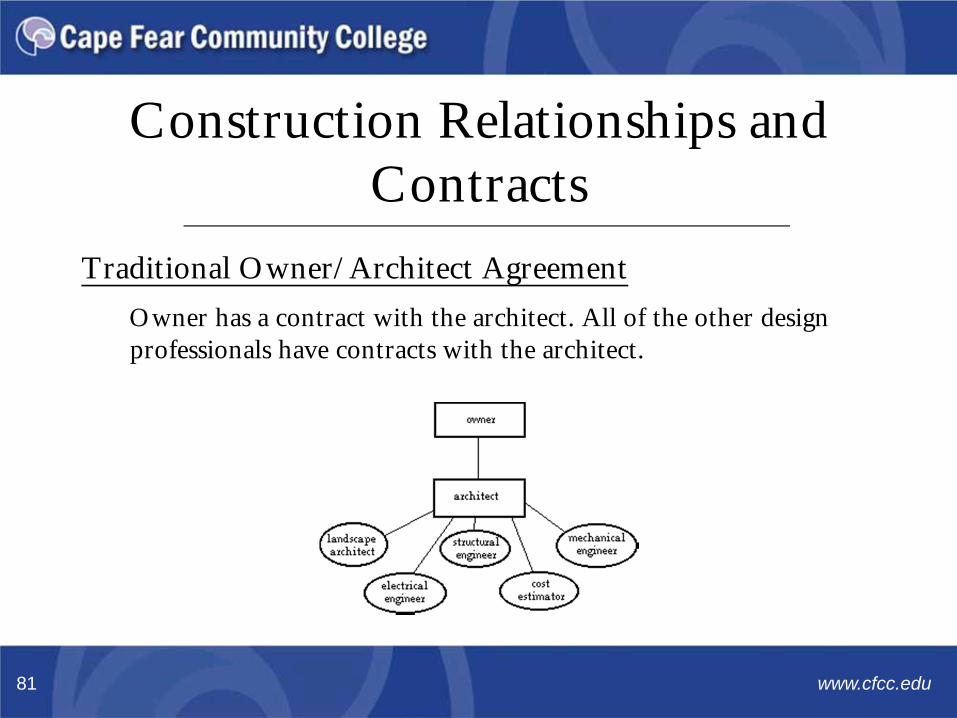
Traditional Owner/Architect AgreementOwner has a contract with the architect. All of the other design professionals have contracts with the architect.

Construction Relationships and Contracts
www.cfcc.edu82
Traditional Owner/Architect AgreementAdvantages
Owner only needs to deal with one entity, the architectDisadvantages
Architect may want to use engineering or other consultants that the owner doesn't want
Owner doesn't have direct access to some team members. All information is filtered through the architect.

Construction Relationships and Contracts
www.cfcc.edu83
Multi-Prime AgreementsOwner has separate contracts with some or all members of the design team. Some firms may have subcontracts with a prime firm

Construction Relationships and Contracts
www.cfcc.edu84
Multi-Prime AgreementsAdvantages
Owner can select team members that they want Critical team members can be directly responsible to the
ownerDisadvantages
Responsibilities may be confused, especially in the area of coordination
Owner is the only means of resolving disputes between team members.

Construction Relationships and Contracts
www.cfcc.edu85
Conventional Design, Bid, BuildThis is the traditional arrangement in modern American construction
Owner hires an architect who prepares plans and specifications
Contract is awarded from the owner to the contractor who offers to build the work for the lowest price.
Construction Relationships and Contracts
www.cfcc.edu86
Conventional Design, Bid, BuildAdvantages
It's simple Everyone is familiar with the process and the
relationshipsDisadvantages Contractors can offer an artificially low bid, then find
ways of charging exorbitant amounts for extras during construction
Design team can't take advantage of the expertise of the contractor during design.

www.cfcc.edu87
Project Specifications
Project SpecificationsA project specification is an essential part of the design, and stateshow the work should be executed to ensure that it meets thedesigner’s assumptions.
Provide detailed guidance on project outputs
Provide that guidance through the written word,coupled with graphics and drawings
Provide clear direction to tolerances and standards.
www.cfcc.edu88

Project SpecificationsDescription
The specification or “spec”, is the document used to prepare jobbids
A legal, contractual document
Normally written by a professional in the fire alarm orfire protection field
Someone other than a fire alarm professional or fireprotection engineer (FPE), it should be reviewed foraccuracy, completeness and compliance
• This review should be done by someone with aNICET Level III or IV certification.
www.cfcc.edu89

Project SpecificationsParts and Types
Specifications are important since they are legal contractualdocuments
Specifications are usually divided into three parts1. General Clauses and Agreements2. Technical Instructions3. Acceptance of the System
Two general types used for fire alarm signaling systems1. Vendor’s specifications that concern equipment2. Engineering specifications that concern system
performance.
www.cfcc.edu90
Project SpecificationsContract Documents
Fire alarm requirements are determined from the HVAC,Mechanical or Electrical part of the specification
Division 15 – Mechanical• HVAC System: Duct alarm shall shut down HVAC• Supply Side: 2,000 CFM or greater• Return Side: 15.000 CFM and two or more floors
Division 16 – Electrical• Access Control Systems – Doors shall unlock on
alarm• Sprinkler system shall be tied into fire alarm system• Suppression System shall be tied into fire alarm
system.www.cfcc.edu91

Fire Alarm Systems Training
Questions?
www.cfcc.edu92

Contact Information
@fast_ilm
Cape Fear Community College4500 Blue Clay RoadCastle Hayne, NC 28429www.cfcc.edu
Thank You!
www.cfcc.edu93