aix 5l on the ibm system i platform: implementation guide · iv aix 5l on the ibm system i...
TRANSCRIPT

ibm.com/redbooks
Front cover
AIX 5L on the IBM System i PlatformImplementation Guide
Michael GilleyGrant Wang
Yessong Johng
Discussion of logical partitions on the IBM POWER5 technology-based System i platform
Description of new devices and products that are supported
Step-by-step installation guide for AIX on the System i platform


International Technical Support Organization
AIX 5L on the IBM System i Platform: Implementation Guide
December 2006
SG24-6455-01

© Copyright International Business Machines Corporation 2005. All rights reserved.Note to U.S. Government Users Restricted Rights -- Use, duplication or disclosure restricted by GSA ADP ScheduleContract with IBM Corp.
Second Edition (December 2006)
This edition applies to V5R4 of i5/OS and AIX 5L V5.2 and V5.3.
Note: Before using this information and the product it supports, read the information in “Notices” on page v.

Contents
Notices . . . . . . . . . . . . . . . . . . . . . . . . . . . . . . . . . . . . . . . . . . . . . . . . . . . . . . . . . . . . . . . . . .vTrademarks . . . . . . . . . . . . . . . . . . . . . . . . . . . . . . . . . . . . . . . . . . . . . . . . . . . . . . . . . . . . . . vi
Preface . . . . . . . . . . . . . . . . . . . . . . . . . . . . . . . . . . . . . . . . . . . . . . . . . . . . . . . . . . . . . . . . . viiThe team that wrote this IBM Redbooks publication . . . . . . . . . . . . . . . . . . . . . . . . . . . . . . . viiBecome a published author . . . . . . . . . . . . . . . . . . . . . . . . . . . . . . . . . . . . . . . . . . . . . . . . . viiiComments welcome. . . . . . . . . . . . . . . . . . . . . . . . . . . . . . . . . . . . . . . . . . . . . . . . . . . . . . . . ix
Chapter 1. Overview of AIX 5L on System i . . . . . . . . . . . . . . . . . . . . . . . . . . . . . . . . . . . 11.1 Benefits of running AIX 5L on System i. . . . . . . . . . . . . . . . . . . . . . . . . . . . . . . . . . . . . . 2
1.1.1 AIX 5L System i and System p compatibility. . . . . . . . . . . . . . . . . . . . . . . . . . . . . . 21.1.2 Application flexibility . . . . . . . . . . . . . . . . . . . . . . . . . . . . . . . . . . . . . . . . . . . . . . . . 21.1.3 System i Virtualization Engine. . . . . . . . . . . . . . . . . . . . . . . . . . . . . . . . . . . . . . . . . 2
1.2 Virtual I/O versus direct I/O . . . . . . . . . . . . . . . . . . . . . . . . . . . . . . . . . . . . . . . . . . . . . . . 31.2.1 Virtual I/O: Hosted AIX 5L partition . . . . . . . . . . . . . . . . . . . . . . . . . . . . . . . . . . . . . 31.2.2 Direct I/O: Non-hosted AIX 5L partition. . . . . . . . . . . . . . . . . . . . . . . . . . . . . . . . . . 41.2.3 Comparison of virtual I/O and direct I/O . . . . . . . . . . . . . . . . . . . . . . . . . . . . . . . . . 41.2.4 Typical implementation scenarios . . . . . . . . . . . . . . . . . . . . . . . . . . . . . . . . . . . . . . 5
1.3 POWER hypervisor . . . . . . . . . . . . . . . . . . . . . . . . . . . . . . . . . . . . . . . . . . . . . . . . . . . . . 61.4 HMC overview. . . . . . . . . . . . . . . . . . . . . . . . . . . . . . . . . . . . . . . . . . . . . . . . . . . . . . . . . 81.5 Concepts and terminology . . . . . . . . . . . . . . . . . . . . . . . . . . . . . . . . . . . . . . . . . . . . . . . 9
1.5.1 Processor concepts . . . . . . . . . . . . . . . . . . . . . . . . . . . . . . . . . . . . . . . . . . . . . . . . 91.6 Readers’ guide to this IBM Redbooks publication. . . . . . . . . . . . . . . . . . . . . . . . . . . . . 10
Chapter 2. Planning for AIX 5L on System i . . . . . . . . . . . . . . . . . . . . . . . . . . . . . . . . . . 132.1 Virtual I/O scenario . . . . . . . . . . . . . . . . . . . . . . . . . . . . . . . . . . . . . . . . . . . . . . . . . . . . 142.2 Direct I/O scenario . . . . . . . . . . . . . . . . . . . . . . . . . . . . . . . . . . . . . . . . . . . . . . . . . . . . 182.3 Planning for virtual I/O. . . . . . . . . . . . . . . . . . . . . . . . . . . . . . . . . . . . . . . . . . . . . . . . . . 19
2.3.1 AIX 5L Virtual I/O Server (VIOS) overview . . . . . . . . . . . . . . . . . . . . . . . . . . . . . . 192.3.2 Considerations for virtual I/O scenarios . . . . . . . . . . . . . . . . . . . . . . . . . . . . . . . . 192.3.3 Hardware requirements for a hosted AIX 5L partition . . . . . . . . . . . . . . . . . . . . . . 20
2.4 Planning for direct I/O . . . . . . . . . . . . . . . . . . . . . . . . . . . . . . . . . . . . . . . . . . . . . . . . . . 212.4.1 Considerations for direct I/O scenarios . . . . . . . . . . . . . . . . . . . . . . . . . . . . . . . . . 212.4.2 Hardware requirements for an AIX 5L logical partition . . . . . . . . . . . . . . . . . . . . . 21
2.5 Planning for network . . . . . . . . . . . . . . . . . . . . . . . . . . . . . . . . . . . . . . . . . . . . . . . . . . . 262.6 Planning for hybrid: Virtual and direct I/O mixed. . . . . . . . . . . . . . . . . . . . . . . . . . . . . . 26
2.6.1 All direct I/O except virtual CD/DVD . . . . . . . . . . . . . . . . . . . . . . . . . . . . . . . . . . . 272.6.2 Direct network adapter and virtual storage . . . . . . . . . . . . . . . . . . . . . . . . . . . . . . 272.6.3 Direct storage and virtual LAN . . . . . . . . . . . . . . . . . . . . . . . . . . . . . . . . . . . . . . . 27
2.7 Current considerations of AIX 5L on System i . . . . . . . . . . . . . . . . . . . . . . . . . . . . . . . 272.7.1 Virtual I/O considerations . . . . . . . . . . . . . . . . . . . . . . . . . . . . . . . . . . . . . . . . . . . 272.7.2 Direct I/O considerations. . . . . . . . . . . . . . . . . . . . . . . . . . . . . . . . . . . . . . . . . . . . 272.7.3 Virtual and direct I/O hybrid considerations . . . . . . . . . . . . . . . . . . . . . . . . . . . . . 27
Chapter 3. Partition configuration . . . . . . . . . . . . . . . . . . . . . . . . . . . . . . . . . . . . . . . . . . 293.1 Concepts and terminology . . . . . . . . . . . . . . . . . . . . . . . . . . . . . . . . . . . . . . . . . . . . . . 303.2 Verify available resources . . . . . . . . . . . . . . . . . . . . . . . . . . . . . . . . . . . . . . . . . . . . . . . 313.3 Initial partition settings. . . . . . . . . . . . . . . . . . . . . . . . . . . . . . . . . . . . . . . . . . . . . . . . . . 34
3.3.1 Create the logical partition . . . . . . . . . . . . . . . . . . . . . . . . . . . . . . . . . . . . . . . . . . 34
© Copyright IBM Corp. 2005. All rights reserved. iii
3.4 I/O settings for virtual I/O . . . . . . . . . . . . . . . . . . . . . . . . . . . . . . . . . . . . . . . . . . . . . . . 443.4.1 Modify existing partition profile . . . . . . . . . . . . . . . . . . . . . . . . . . . . . . . . . . . . . . . 443.4.2 DLPAR process . . . . . . . . . . . . . . . . . . . . . . . . . . . . . . . . . . . . . . . . . . . . . . . . . . 463.4.3 Virtual I/O definitions in AIX 5L partition profile. . . . . . . . . . . . . . . . . . . . . . . . . . . 473.4.4 Virtual I/O definitions in i5/OS partition profile. . . . . . . . . . . . . . . . . . . . . . . . . . . . 59
Chapter 4. Storage configuration . . . . . . . . . . . . . . . . . . . . . . . . . . . . . . . . . . . . . . . . . . 694.1 Virtual I/O . . . . . . . . . . . . . . . . . . . . . . . . . . . . . . . . . . . . . . . . . . . . . . . . . . . . . . . . . . . 70
4.1.1 Network Server Description . . . . . . . . . . . . . . . . . . . . . . . . . . . . . . . . . . . . . . . . . 704.1.2 Network Server Storage Space. . . . . . . . . . . . . . . . . . . . . . . . . . . . . . . . . . . . . . . 754.1.3 Performance considerations . . . . . . . . . . . . . . . . . . . . . . . . . . . . . . . . . . . . . . . . . 77
4.2 Direct I/O . . . . . . . . . . . . . . . . . . . . . . . . . . . . . . . . . . . . . . . . . . . . . . . . . . . . . . . . . . . . 804.2.1 Configuration of Direct I/O disk units. . . . . . . . . . . . . . . . . . . . . . . . . . . . . . . . . . . 804.2.2 Configuring iSeries disk units for AIX 5L RAID . . . . . . . . . . . . . . . . . . . . . . . . . . . 824.2.3 SCSI disk units under AIX 5L . . . . . . . . . . . . . . . . . . . . . . . . . . . . . . . . . . . . . . . . 834.2.4 SCSI disk unit preparation . . . . . . . . . . . . . . . . . . . . . . . . . . . . . . . . . . . . . . . . . . 844.2.5 Using iSeries Disk units with AIX 5L and a Non-RAID SCSI Controller . . . . . . . . 89
Chapter 5. Network configuration . . . . . . . . . . . . . . . . . . . . . . . . . . . . . . . . . . . . . . . . . . 915.1 Physical network adapters . . . . . . . . . . . . . . . . . . . . . . . . . . . . . . . . . . . . . . . . . . . . . . 92
5.1.1 AIX 5L physical network adapter allocation . . . . . . . . . . . . . . . . . . . . . . . . . . . . . 925.2 Virtual network adapters . . . . . . . . . . . . . . . . . . . . . . . . . . . . . . . . . . . . . . . . . . . . . . . . 93
5.2.1 Adding virtual Ethernet adapter to i5/OS partition. . . . . . . . . . . . . . . . . . . . . . . . . 935.2.2 Creating the Ethernet Line Description in i5/OS . . . . . . . . . . . . . . . . . . . . . . . . . 1005.2.3 Enable datagram forwarding. . . . . . . . . . . . . . . . . . . . . . . . . . . . . . . . . . . . . . . . 1035.2.4 Proxy ARP . . . . . . . . . . . . . . . . . . . . . . . . . . . . . . . . . . . . . . . . . . . . . . . . . . . . . 1045.2.5 Network Address Translation . . . . . . . . . . . . . . . . . . . . . . . . . . . . . . . . . . . . . . . 1075.2.6 Other approaches . . . . . . . . . . . . . . . . . . . . . . . . . . . . . . . . . . . . . . . . . . . . . . . . 119
Chapter 6. AIX 5L installation . . . . . . . . . . . . . . . . . . . . . . . . . . . . . . . . . . . . . . . . . . . . 1216.1 New virtual CD-ROM installation process . . . . . . . . . . . . . . . . . . . . . . . . . . . . . . . . . . 122
6.1.1 Requirements . . . . . . . . . . . . . . . . . . . . . . . . . . . . . . . . . . . . . . . . . . . . . . . . . . . 1226.1.2 Process . . . . . . . . . . . . . . . . . . . . . . . . . . . . . . . . . . . . . . . . . . . . . . . . . . . . . . . . 122
6.2 Physical CD-ROM installation . . . . . . . . . . . . . . . . . . . . . . . . . . . . . . . . . . . . . . . . . . . 1276.2.1 Physical CD-ROM boot device selection . . . . . . . . . . . . . . . . . . . . . . . . . . . . . . 1286.2.2 AIX 5L operating system installation . . . . . . . . . . . . . . . . . . . . . . . . . . . . . . . . . . 131
6.3 Using bottom slim line CD-ROM/DVD drive . . . . . . . . . . . . . . . . . . . . . . . . . . . . . . . . 1406.3.1 Requirements . . . . . . . . . . . . . . . . . . . . . . . . . . . . . . . . . . . . . . . . . . . . . . . . . . . 1416.3.2 Process . . . . . . . . . . . . . . . . . . . . . . . . . . . . . . . . . . . . . . . . . . . . . . . . . . . . . . . . 141
Related publications . . . . . . . . . . . . . . . . . . . . . . . . . . . . . . . . . . . . . . . . . . . . . . . . . . . . 143IBM Redbooks . . . . . . . . . . . . . . . . . . . . . . . . . . . . . . . . . . . . . . . . . . . . . . . . . . . . . . . . . . 143Other publications . . . . . . . . . . . . . . . . . . . . . . . . . . . . . . . . . . . . . . . . . . . . . . . . . . . . . . . 143Online resources . . . . . . . . . . . . . . . . . . . . . . . . . . . . . . . . . . . . . . . . . . . . . . . . . . . . . . . . 143How to get IBM Redbooks . . . . . . . . . . . . . . . . . . . . . . . . . . . . . . . . . . . . . . . . . . . . . . . . . 144Help from IBM . . . . . . . . . . . . . . . . . . . . . . . . . . . . . . . . . . . . . . . . . . . . . . . . . . . . . . . . . . 144
Index . . . . . . . . . . . . . . . . . . . . . . . . . . . . . . . . . . . . . . . . . . . . . . . . . . . . . . . . . . . . . . . . . 145
iv AIX 5L on the IBM System i Platform: Implementation Guide

Notices
This information was developed for products and services offered in the U.S.A.
IBM may not offer the products, services, or features discussed in this document in other countries. Consult your local IBM representative for information on the products and services currently available in your area. Any reference to an IBM product, program, or service is not intended to state or imply that only that IBM product, program, or service may be used. Any functionally equivalent product, program, or service that does not infringe any IBM intellectual property right may be used instead. However, it is the user's responsibility to evaluate and verify the operation of any non-IBM product, program, or service.
IBM may have patents or pending patent applications covering subject matter described in this document. The furnishing of this document does not give you any license to these patents. You can send license inquiries, in writing, to: IBM Director of Licensing, IBM Corporation, North Castle Drive Armonk, NY 10504-1785 U.S.A.
The following paragraph does not apply to the United Kingdom or any other country where such provisions are inconsistent with local law: INTERNATIONAL BUSINESS MACHINES CORPORATION PROVIDES THIS PUBLICATION "AS IS" WITHOUT WARRANTY OF ANY KIND, EITHER EXPRESS OR IMPLIED, INCLUDING, BUT NOT LIMITED TO, THE IMPLIED WARRANTIES OF NON-INFRINGEMENT, MERCHANTABILITY OR FITNESS FOR A PARTICULAR PURPOSE. Some states do not allow disclaimer of express or implied warranties in certain transactions, therefore, this statement may not apply to you.
This information could include technical inaccuracies or typographical errors. Changes are periodically made to the information herein; these changes will be incorporated in new editions of the publication. IBM may make improvements and/or changes in the product(s) and/or the program(s) described in this publication at any time without notice.
Any references in this information to non-IBM Web sites are provided for convenience only and do not in any manner serve as an endorsement of those Web sites. The materials at those Web sites are not part of the materials for this IBM product and use of those Web sites is at your own risk.
IBM may use or distribute any of the information you supply in any way it believes appropriate without incurring any obligation to you.
Information concerning non-IBM products was obtained from the suppliers of those products, their published announcements or other publicly available sources. IBM has not tested those products and cannot confirm the accuracy of performance, compatibility or any other claims related to non-IBM products. Questions on the capabilities of non-IBM products should be addressed to the suppliers of those products.
This information contains examples of data and reports used in daily business operations. To illustrate them as completely as possible, the examples include the names of individuals, companies, brands, and products. All of these names are fictitious and any similarity to the names and addresses used by an actual business enterprise is entirely coincidental.
COPYRIGHT LICENSE: This information contains sample application programs in source language, which illustrates programming techniques on various operating platforms. You may copy, modify, and distribute these sample programs in any form without payment to IBM, for the purposes of developing, using, marketing or distributing application programs conforming to the application programming interface for the operating platform for which the sample programs are written. These examples have not been thoroughly tested under all conditions. IBM, therefore, cannot guarantee or imply reliability, serviceability, or function of these programs. You may copy, modify, and distribute these sample programs in any form without payment to IBM for the purposes of developing, using, marketing, or distributing application programs conforming to IBM's application programming interfaces.
© Copyright IBM Corp. 2005. All rights reserved. v

TrademarksThe following terms are trademarks of the International Business Machines Corporation in the United States, other countries, or both:
AIX 5L™AIX®AS/400®BladeCenter®Domino®eServer™Focal Point™i5/OS®
IBM®IntelliStation®iSeries®Micro-Partitioning™OS/400®POWER4™POWER5™POWER®
pSeries®Redbooks®Redbooks (logo) ®RS/6000®System i®System p®System x®WebSphere®
The following terms are trademarks of other companies:
Java, Ultra, and all Java-based trademarks are trademarks of Sun Microsystems, Inc. in the United States, other countries, or both.
Active Directory, Windows, and the Windows logo are trademarks of Microsoft Corporation in the United States, other countries, or both.
Intel, Intel logo, Intel Inside logo, and Intel Centrino logo are trademarks or registered trademarks of Intel Corporation or its subsidiaries in the United States, other countries, or both.
UNIX is a registered trademark of The Open Group in the United States and other countries.
Linux is a trademark of Linus Torvalds in the United States, other countries, or both.
Other company, product, and service names may be trademarks or service marks of others.
vi AIX 5L on the IBM System i Platform: Implementation Guide

Preface
On the IBM® System i® platform, you can run native AIX® 5L™ with its own kernel (versus current the PASE SLIC kernel) in a logical partition (LPAR). This option provides another alternative to consolidate AIX 5L applications and other UNIX®-based applications, running in a separate IBM eServer™ pSeries® system or other UNIX system, onto a single System i platform.
With the new version of the AIX 5L V5.3 operating system, the same level of server virtualization, such as dynamic resource allocation, is realized as the current IBM eServer iSeries® level server virtualization.
This IBM Redbooks® publication discusses various aspects of AIX 5L implementation on IBM System i platforms. It includes the following topics:
� An overview of AIX 5L native support on the System i platform including the benefits of a virtualization engine
� Planning for AIX 5L on the System i platform, with an explanation about new LPAR concepts and tools on the System i platform and initial sizing of an AIX 5L partition
� Installation and configuration of an AIX 5L partition on the System i platform, providing a step-by-step guide for AIX 5L installation, partition setup, and maintenance that includes a scenario of virtual I/O and direct I/O
This book helps system administrators to install, tailor, and configure an AIX 5L partition on the System i platform.
The team that wrote this IBM Redbooks publicationThis IBM Redbooks publication was produced by a team of specialists from around the world working at the International Technical Support Organization, Rochester Center.
Yessong Johng is an IBM Certified IT Specialist at the IBM International Technical Support Organization, Rochester Center. He started his IT career at IBM as a S/38 Systems Engineer in 1982, and he worked with S/38, AS/400®, iSeries, and now System i for 20 years. He writes extensively and develops and teaches IBM classes worldwide in the areas of IT optimization whose topics include Linux®, AIX 5L, and Windows® implementations on the System i platform. He is also interested in e-business, especially concerning WebSphere® implementations on the System i platform.
Michael Gilley is a Staff Software Engineer at the IBM Rochester Center. He has been with IBM since 1997, and he has worked on the Domino® for iSeries Support Team, the iSeries Communications Support Team, as well as BlueGene support. He is currently working on the iSeries Integration Support Team, supporting System i Integration with BladeCenter® and System x® as well as installations of AIX 5L and Linux on the System i platform.
Grant Wang is an Advisory IT Specialist for Sales and Distribution, IBM China. Grant has five years experience with iSeries post-sale technical support for iSeries customers in China. He is also experienced in developing iSeries client/server applications with comprehensive knowledge about multivendor platforms that include AIX, OS/400®, Linux, Windows, WebSphere, MQ Series, TSM, and UDB.
© Copyright IBM Corp. 2005. All rights reserved. vii

This edition was based on the first edition of the book whose authors were:
Martin BalazFredy CruzJim DounisMaciej JedrzejczakEdith LuekeVess NatchevDan O’HareLeif RushClem Seibert
Thanks to the following people for their contributions to this project:
Vess NatchevErwin EarleyFant SteeleDavid BoutcherMonte BruesewitzCraig JohnsonEdith LuekeDan O’HareTracy SmithGeoffrey WarrenIBM Rochester
Vishal AslotDavid RuthScott VetterChristine Iju WangAnn WingintonIBM Austin
Jim CioffiIBM Dallas
Doug MackIBM Seattle
Become a published authorJoin us for a two- to six-week residency program! Help write IBM Redbooks dealing with specific products or solutions, while getting hands-on experience with leading-edge technologies. You'll team with IBM technical professionals, Business Partners and/or customers.
Your efforts will help increase product acceptance and customer satisfaction. As a bonus, you will develop a network of contacts in IBM development labs, and increase your productivity and marketability.
Find out more about the residency program, browse the residency index, and apply online at:
ibm.com/redbooks/residencies.html
viii AIX 5L on the IBM System i Platform: Implementation Guide

Comments welcomeYour comments are important to us!
We want our Redbooks to be as helpful as possible. Send us your comments about this or other Redbooks in one of the following ways:
� Use the online Contact us review IBM Redbooks form found at:
ibm.com/redbooks
� Send your comments in an email to:
� Mail your comments to:
IBM Corporation, International Technical Support OrganizationDept. JLU Building 107-23605 Highway 52NRochester, Minnesota 55901-7829
Preface ix

x AIX 5L on the IBM System i Platform: Implementation Guide
Chapter 1. Overview of AIX 5L on System i
AIX 5L is rapidly emerging as the preferred platform for UNIX users and independent software vendors. AIX 5L delivers industrial strength UNIX reliability, availability and security while offering flexible system administration and ease of integration with Linux. With innovative virtualization and Micro-Partitioning™, AIX 5L helps you make no compromises and accept no limits in the on demand world.
AIX 5L is open and standards-based, and it is designed to conform to The Open Group's Single UNIX Specification Version 3. It provides fully integrated support for 32-bit and 64-bit applications running concurrently, in their full range of scalability. AIX 5L supports the IBM System i, IBM System p®, IBM eServer p5, IBM eServer pSeries, and IBM RS/6000® server product lines, as well as IntelliStation® POWER® and RS/6000 workstations.
You can run AIX 5L on System i in logical partitions that allow you to optimize your investments: share processor and memory resource, move resources to where they are needed, exploit i5/OS® storage subsystem, and leverage skills and best practices.
1
© Copyright IBM Corp. 2005. All rights reserved. 1

1.1 Benefits of running AIX 5L on System iWith the new version of hypervisor for POWER5™, System i supports all three operating systems of i5/OS, AIX 5L, and Linux on POWER natively. This means AIX 5L running on IBM System i and IBM System p are identical operating system in every sense including Kernel and all. In addition to this increased flexibility of applications choice, there are other significant benefits of running AIX 5L on IBM System i.
1.1.1 AIX 5L System i and System p compatibilityWith the announcement of System p and the availability of AIX 5L V5.2ML4 and AIX 5L V5.3, customers, business partners and independent software vendors can deploy applications running on AIX 5L v5.2 or AIX 5L v5.3 on either System i or System p systems.
Since IBM System i and IBM System p are built with the same POWER5 processors and server technology, AIX 5L applications that run on System p can run on System i unchanged. While most of the I/O options are the same between the System i and System p, support is dependent upon specific I/O availability. You should verify that adapters running in AIX 5L partitions on System i servers are utilizing I/O Adapters supported by AIX 5L. Some selected AIX 5L licensed program products are not available on the System i platform.
1.1.2 Application flexibilityIBM System i maintains its focus on business applications, a focus which began with the AS/400 and continued with IBM eServer iSeries. The support of AIX 5L on System i servers offers customers more choices of solutions to meet business needs. In addition to the numerous i5/OS applications and portfolio of Windows applications available on System i via Integrated IBM System x technology and the hundreds of available Linux applications supported on Linux on POWER, System i customers can choose to run AIX 5L applications as well.
Choosing an application should be about finding the best solution to meet your business demands, not just the ones that fit a single operating system. With the growing complexities of business, many customers find that no single operating system has all the solutions to meet their business requirements. How can your server infrastructure support solutions running on diverse operating systems while maintaining infrastructure simplicity? If you own a System i server, it is easy. Choose from the vast selection of i5/OS, Windows, Linux and now, AIX 5L applications and deploy them on a System i server while making use of virtualization and systems management technologies which simplify managing all four operating systems on a single server.
1.1.3 System i Virtualization EngineThe System i servers are designed to pool resources and optimize their use across multiple application environments and operating systems. This is managed by the POWER hypervisor (1.3, “POWER hypervisor” on page 6). Through advanced Micro-Partitioning (LPAR) capabilities, System i servers support running i5/OS, AIX 5L, Linux and Windows (via IXA or IXS) at the same time on a single server — giving companies the freedom to run a wide variety of business applications without the costs and complexity often associated with managing multiple physical servers.
A single partition acts as a completely separate i5/OS, Linux, or AIX 5L server. With the capacity to support up to ten dynamic LPARs per processor, System i servers can help simplify IT infrastructures by allowing companies to deploy new applications and consolidate
2 AIX 5L on the IBM System i Platform: Implementation Guide
operations on a single, highly flexible, resilient server. LPAR enables System i servers to adjust pooled processor resources automatically across operating systems by borrowing processing power from idle partitions to help handle high transaction volumes in other partitions. Consolidating your systems with LPAR can help cut operational costs, improve availability management and service levels, quickly deploy applications, increase your ability to rationalize and modernize networks, and centralize international operations.
The System i delivers an advanced storage architecture that provides more flexibility than conventional UNIX, Windows and Linux server implementations. With the System i, all disk units can be managed as a single pool of RAID-5 or mirrored, protected storage—helping to simplify data administration and improve productivity by boosting storage utilization rates. One pool of disk units can be managed by an i5/OS partition, and space can be allocated to each of the multiple operating systems. One consolidated backup can greatly reduce the costs and effort to protect company data stored in applications on a variety of servers. Through storage virtualization, the System i can deliver excellent performance to multiple applications, maximize the utilization of the storage resources, and reduce the storage management costs typically associated with server farms.
Logical partitions can also use Virtual Ethernet technology on the System i server. Over 4,000 individual virtual networks can be defined to provide fast (up to 1 Gbit/second), very secure connections among these multiple operating systems, for effective application-to-application communications.
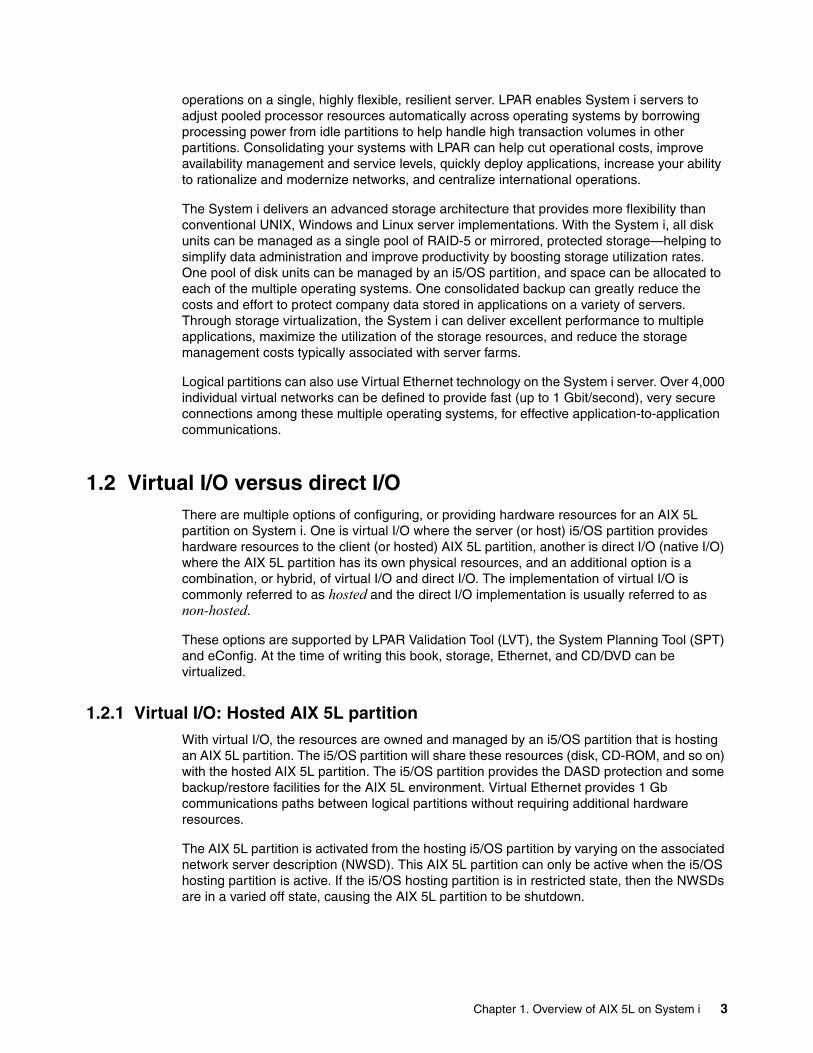
1.2 Virtual I/O versus direct I/OThere are multiple options of configuring, or providing hardware resources for an AIX 5L partition on System i. One is virtual I/O where the server (or host) i5/OS partition provides hardware resources to the client (or hosted) AIX 5L partition, another is direct I/O (native I/O) where the AIX 5L partition has its own physical resources, and an additional option is a combination, or hybrid, of virtual I/O and direct I/O. The implementation of virtual I/O is commonly referred to as hosted and the direct I/O implementation is usually referred to as non-hosted.
These options are supported by LPAR Validation Tool (LVT), the System Planning Tool (SPT) and eConfig. At the time of writing this book, storage, Ethernet, and CD/DVD can be virtualized.
1.2.1 Virtual I/O: Hosted AIX 5L partitionWith virtual I/O, the resources are owned and managed by an i5/OS partition that is hosting an AIX 5L partition. The i5/OS partition will share these resources (disk, CD-ROM, and so on) with the hosted AIX 5L partition. The i5/OS partition provides the DASD protection and some backup/restore facilities for the AIX 5L environment. Virtual Ethernet provides 1 Gb communications paths between logical partitions without requiring additional hardware resources.
The AIX 5L partition is activated from the hosting i5/OS partition by varying on the associated network server description (NWSD). This AIX 5L partition can only be active when the i5/OS hosting partition is active. If the i5/OS hosting partition is in restricted state, then the NWSDs are in a varied off state, causing the AIX 5L partition to be shutdown.
Chapter 1. Overview of AIX 5L on System i 3

1.2.2 Direct I/O: Non-hosted AIX 5L partitionWith direct I/O, the resources are owned by and are under the control of the AIX 5L partition. It is not dependent upon an i5/OS partition for any resources; consequently, no i5/OS partition can use these resources since they are allocated to the AIX 5L partition. For directly attached hardware, all failure and diagnostic messages are managed within the AIX 5L partition.
Usually, direct I/O is used when performance is critical, because direct I/O is often faster to use than virtual I/O.
Also, with direct I/O, an AIX 5L partition can be active even when an i5/OS partition is not active, which is not the case in a virtual I/O scenario.
1.2.3 Comparison of virtual I/O and direct I/OSo, when should you use virtual I/O or direct I/O? The answer depends on user requirements and available resources. In order to help you decide, you can refer to Table 1-1.
AIX 5L can take advantage of both virtual and direct I/O resources at the same time. Also, it is possible to switch from virtual I/O to direct I/O or vice versa once we realize that other solution will fit better.
Table 1-1 Direct I/O versus Virtual I/O versus Hybrid I/O
Requirements Advantages Disadvantages
Direct I/O One LAN adapter0.1 CPU256 MB RAMOne DASD with a minimum size of 512 MBDedicated CD-ROM
Completely independent of other partitions.
You need more hardware, and there is administrative overhead (backup and hardware maintenance).
Virtual I/O 0.1 CPU256 MB RAMOne VLAN512 MB Free on i5/OSVirtual CD-ROM
There is no need for physical hardware or sharing resources, and the VLAN is secure, fast, and can reduce congestion on the external network. There is a single backup procedure, and it is flexible.
The performance is dependent on i5/OS, you need some i5/OS resources, and the downtime of i5/OS is the downtime of the hosted partition as well. Completely dependent upon the hosting i5/OS partition.
Hybrid I/O 0.1 CPU256 MB RAMOne VLAN or One LAN adapterOne DASD with minimum size of 512 MB or 512 MB Free on i5/OSVirtual or dedicated CD-ROM
You combine direct I/O and virtual I/O for the best cost/benefit ratio
Complex.
4 AIX 5L on the IBM System i Platform: Implementation Guide

1.2.4 Typical implementation scenariosAs AIX 5L can take advantage of virtual and direct I/O resources at the same time, some common configurations are hybrid. For example, combining direct and virtual I/O at the same time.
A very popular scenario is what we call a typical hybrid scenario: You have all the I/O devices served by an i5/OS partition (virtual I/O), except for the network connections (direct I/O for network adapters). You can easily set up a firewall or even a demilitarized zone (DMZ) scenario that way.
Benefits of virtualizationAs briefly described previously in 1.1, “Benefits of running AIX 5L on System i” on page 2, the benefits of server consolidation can be maximized with virtual I/O. These benefits are realized in the forms and shapes of consolidated backup, more disk arms, centralized management, and flexibility to add or change your configuration.
Virtual I/O features� Virtual disk units created in i5/OS storage system
– Each virtual disk can be the size of 1 MB to 1 TB
– Each AIX 5L partition can have up to 64 virtual disks making the maximum disk space of one AIX 5L server to be 64 TB
� Storage dynamically added to AIX 5L partitions
� Read-only storage shared by multiple AIX 5L partitions
Virtual I/O benefits� Data automatically spread to more disk arms and protected by i5/OS (RAID, mirroring)
� Consolidated backup of i5/OS and AIX 5L data (along with Linux on POWER and Linux on Intel® data which all reside on virtual disks which are created and maintained by i5/OS)
� Easy "cloning" of a "good" AIX 5L image
� Easy setup or recycling of multiple AIX 5L environments
� AIX 5L test kernels can be stored in i5/OS files
� Do analysis of crash by linking the crash image to a booted working image
Chapter 1. Overview of AIX 5L on System i 5

1.3 POWER hypervisorThe technology behind the virtualization of the IBM System i is provided by a piece of firmware known as the POWER hypervisor, which resides in flash memory. This firmware performs the initialization and configuration of the POWER5 processor, as well as the virtualization support required to run up to 254 partitions concurrently on the IBM System i.
The POWER hypervisor supports many advanced functions when compared to the previous version found in POWER4™ processor–based systems. This includes sharing of processors, virtual I/O, and high-speed communications among partitions using a virtual LAN, and it enables multiple operating systems to run on the single system. Currently, the AIX 5L, Linux, and i5/OS operating systems are supported, as shown in Figure 1-1.
With support for dynamic resource movement across multiple environments, clients can move processors, memory, and I/O between partitions on the system as workloads are moved between the partitions.
Figure 1-1 Virtualization technologies implemented on POWER5 systems
The POWER hypervisor is the underlying control mechanism that resides below the operating systems but above the hardware layer (Figure 1-2 on page 7). It owns all system resources and creates partitions by allocating and sharing them.
Attention: The POWER hypervisor is mandatory on all POWER5 processor–based systems. This includes any single-LPAR system.
Hardware
POWER Hypervisor
I/OServer
Partition
AIXPartitions c
LinuxPartitions
i5/OSPartitions
Virtual Ethernet Virtual Storage
ProcessorResources
MemoryResources
I/OResources Virtual
TTY
ActivePool
CPU
CPU
CPU
CPU
CPU
CPU
CPU
CPUCUoD
CPU
CPU
CPU
CPU
ActivePool
MEM
MEM
MEM
MEM
MEM
MEM
MEM
MEMCUoD
MEM
MEM
MEM
MEM
Active
IOA
IOA
IOA
IOA
IOA
IOA
IOA
IOA
ServiceProcessor
6 AIX 5L on the IBM System i Platform: Implementation Guide

Figure 1-2 IBM System i system layers
The layers above the POWER hypervisor are different for each supported operating system. For the AIX 5L and Linux operating systems, the layers above the POWER hypervisor are similar but the contents are characterized by each operating system. The layers of code supporting AIX 5L and Linux consist of system firmware and Run-Time Abstraction Services (RTAS).
System firmware is composed of low-level firmware (code) that performs server unique input/output (I/O) configurations and the Open Firmware that contains the boot-time drivers, boot manager, and the device drivers required to initialize the PCI adapters and attached devices. RTAS consists of code that supplies platform-dependent accesses and can be called from the operating system. These calls are passed to the POWER hypervisor that handles all I/O interrupts.
The distinction between RTAS and Open Firmware is important. Open Firmware and RTAS are both platform-specific firmware and both are tailored by the platform developer to manipulate the specific platform hardware. RTAS encapsulates some of the machine-dependent operations of the IBM System i systems into a machine-independent package. The operating system can call RTAS to do things such as start and stop processors in an SMP configuration, display status indicators (such as LEDs), and read/write NVRAM without having to know the intricate details of how the low-level functions are implemented on particular platforms. Open Firmware, on the other hand, does not have to be present when the operating system is running.
For i5/OS, Technology Independent Machine Interface (TIMI) and the layers above the POWER hypervisor are still in place. System Licensed Internal Code (SLIC), however, is changed and enabled for interfacing with the POWER hypervisor. The POWER hypervisor code is based on the iSeries Partition Licensed Internal Code (PLIC) code that is enhanced for use with the IBM System i hardware. The PLIC is now part of the POWER hypervisor.
TIMISLIC
ProgramsAIX 5L
OpenFirmwareRTAS
ProgramsLinux
OpenFirmwareRTAS
Programsi5/OS
POWER Hypervisor
POWER 64-bit PROCESSOR
Chapter 1. Overview of AIX 5L on System i 7

1.4 HMC overviewThe Hardware Management Console (HMC) is an IBM PC based, standalone system. It is delivered pre-loaded with the HMC software. It cannot be used for any other purpose. The HMC has a Graphical User Interface (GUI) that runs on a Linux operating system. The GUI is Java™ based. This operating system is restricted to user access to prevent you from customizing or altering the operating system. Even the highest privileged User ID, Root has limited capabilities. The GUI is the primary interface and there is a shell, command line interface with limited function.
HMC functionsHere is a list of some of the HMC functions:
� Manage one or two POWER5� Creating and maintaining LPAR environments� Manage on demand activation of IBM virtualization technologies. Such as:
– Functions to dynamically add or move CPU and memory between LPARs– Functions to add/move/remove physical hardware or virtual I/O to LPARs
� Local console session for i5/OS, AIX 5L and Linux� Remote access through WebSM client� A Single point of hardware error logging for all LPARs - Service Focal Point™� Firmware updates� Capacity on demand� Control panel functions
Managed systemManaged systems are physical servers that are managed by the HMC. This term is the same as the System i - all the hardware (system unit and expansion units). The HMC can manage more than one managed system at a time. Managed systems can have one or more logical partitions (LPAR). These partitions and their profiles define the way that you configure and operate your partitioned server.
i5/OS, AIX 5L and Linux are supported LPAR operating systems that can be installed on the System i. These operating systems will operate as independent logical servers. However, partitions share a few system attributes, such as the system serial number, system model, and processor feature code. All other system attributes may vary among partitions.
The maximum number of partitions has increased to 254. This is limited by the capability of the HMC.
Note: Prior to V5R1 release of HMC, AIX 5L partitions were unable to utilize the bottom slimline CD/DVD drive on IBM eServer i5 Models 520, 520+, 550 and 550+. Starting with V5R1 release of HMC, assigning the Other mass storage controller to an AIX 5L or Linux partition is enabled.
Note: More detailed information about HMC with System i can be found in this IBM Redbooks publication: A Guide to Planning and Configuring LPAR with HMC on System i, SG24-8000.
8 AIX 5L on the IBM System i Platform: Implementation Guide

1.5 Concepts and terminologyHere are some concepts and terms that you need to know as you work with configuration planning for Linux on the System i platform.
1.5.1 Processor conceptsThere are varying options for processor assignments for logical partitions such as dedicated whole processors, shared processors, or fractions of processors. The System i and System p platforms introduce the concept of capped or uncapped partitions. Results of your capacity planning and your system hardware configuration will help you determine your optimal processor assignments for each of your logical partitions. One logical partition may need dedicated processors while another logical partition can use the shared processing pool.
Dedicated processorsWhen a system is logically partitioned using dedicated processors, each processor in its entirety is assigned to a partition. In this case, you would only be allowed two partitions at most with a two-processor system, for example. Each partition would then have only one processor assigned to it. Dedicated processors may get better performance than shared processors, but shared processors are more flexible and allow better use of the processors for multiple partitions.
Shared processors (micro-partitioning)Shared processors allow you to assign fractions of a processor to a logical partition and are held in the shared processing pool. This allows multiple logical partitions to share a processor.
Virtual processorsA virtual processor represents a single physical processor to the operating system of the logical partition. This is a whole number of concurrent operations that the operating system can use. Selecting the optimal number of virtual processors depends on the workload of the partition. One partition may benefit from greater concurrent operations while another partition may benefit from greater power.
The default setting for virtual processors is based on the number of processing units specified for a logical partition. The number of processing units is rounded up to the next whole number to get the minimum number of virtual processors. If you have 1.5 processing units, 2 virtual processors will be assigned by default.
You may want to specify a greater number of virtual processors so that you do not limit the processing capacity of an uncapped partition.
Shared processor poolThe shared processor pool is a group of physical processors that provide processing power to multiple logical partitions. With this shared pool, you can assign fractions of processors (or shared processor units) to logical partitions. There is only one shared processor pool for the system.
When shared processors are used, a physical processor may be moved from one logical partition to another logical partition many times a second. This allows for flexible use of the processor and maximizes processing power across the logical partitions. However, there is a performance impact due to the cost of switching from one logical partition to another. In
Chapter 1. Overview of AIX 5L on System i 9
addition, memory caches are reloaded when processors are switched between logical partitions.
Shared processor unitsShared processor units are a unit of measure for shared processing power across one or more virtual processors. Partitions that use shared processors are assigned these shared processor units. The minimum units that can be assigned to a partition is 0.10 processor units per virtual processor. If two virtual processors are assigned to the logical partition, then 0.20 processor units must be assigned as a minimum.
Capped/uncapped logical partitionsA capped partition is limited to using the number of shared processor units that it has been assigned. It is never allowed to exceed that processing capacity. This allows for very predictable performance and should be used when doing any performance benchmarks.
Uncapped partitions are a feature of the System i and System p platforms. While an uncapped partition is guaranteed the number of shared processor units it has been assigned, it is now allowed to automatically consume any unused processor capacity in the shared pool and in the system pool when dedicated processors are not being used by other logical partitions. An uncapped logical partition can consume unused processor capacity up to its maximum virtual processor setting.
Uncapped partitions are given a relative weight to other uncapped partitions. This weight is a value from 0 to 255 with 255 being the highest weight; the default weight is 128. The i5 system and the POWER hypervisor will move processor resources to other partitions based on the activity in the partitions and the relative weight given to those partitions.
Let us illustrate this point by taking an example: You have a multiple partitioned system. Partitions 1, 2, and 3 are uncapped. Partition 1 has two processing units assigned to it; it is using 50% of its allocated processing resource. Partition 3 has one processing unit assigned to it, but it is running at 100% utilization and is in need of more processing resource. Since partition 3 is uncapped and has two virtual processors, the unused processor units in Partition 1 can be used in Partition 3 thus increasing its processor capacity and allowing it to complete its workload.
If Partition 2 required additional resources at the same time, unused processing capacity could be distributed to both partitions. The distribution would be determined by the uncapped weight of each of the partitions. If Partition 2 had a weight of 100 and Partition 3 had a weight of 200, Partition 3 would get twice the unused processing capacity as Partition 2.
Should Partition 1’s workload increase, it can acquire back its resources.
1.6 Readers’ guide to this IBM Redbooks publicationThis section provides the roadmap, or the structure, of this book:
� Chapter 2, “Planning for AIX 5L on System i” on page 13 reviews the different AIX 5L on System i deployment scenarios.
� Chapter 3, “Partition configuration” on page 29 reviews the partition configuration process for the System i, and focuses on settings that are common to all scenarios.
Note: CUoD processors that have not yet been activated cannot be used by uncapped logical partitions.
10 AIX 5L on the IBM System i Platform: Implementation Guide

� Chapter 4, “Storage configuration” on page 69 reviews the different storage configuration options for an AIX 5L partition. This includes virtual I/O and direct I/O.
� Chapter 5, “Network configuration” on page 91 explains the different ways to establish network connectivity for an AIX 5L partition, with emphasis on virtual Ethernet connectivity.
� Chapter 6, “AIX 5L installation” on page 121 explains the AIX 5L operating system installation process, including the additional enhancement of virtual CD/DVD.
Chapter 1. Overview of AIX 5L on System i 11

12 AIX 5L on the IBM System i Platform: Implementation Guide

Chapter 2. Planning for AIX 5L on System i
In this chapter we review the different AIX 5L on System i deployment scenarios. We discuss each scenario and the advantages and disadvantages of each scenario.
2
© Copyright IBM Corp. 2005. All rights reserved. 13

2.1 Virtual I/O scenarioi5/OS provides virtual storage to AIX 5L partitions where AIX 5L is the client and i5/OS is the server. It allows storage spaces on an i5/OS partition to be allocated to AIX 5L partitions. These disks are presented to the AIX 5L partitions as virtual SCSI disk drives.
This virtual I/O minimizes the requirements of physical adapters and physical disks, that is, hardware to be allocated to a partition. The POWER5 hypervisor is the layer of firmware that acts like a virtual switch/system bus in the System i.
Virtual I/O support starts at AIX 5L V5.3, while it has been available on OS/400 since V4R5 although its implementation is now different with POWER5.
Virtual I/O slotsEach partition has virtual I/O slots. When virtual I/O adapters are created, they are allocated a slot, and each of slot has a unique number in the partition profile. The slot number refers to the position of the virtual I/O adapter on the virtual system bus.
The types of virtual I/O adapters are:
� Virtual Ethernet adapter � Virtual SCSI adapter� Virtual serial adapter
The SCSI and serial virtual I/O adapters are a server or client adapter type.
Consider an i5/OS partition serving virtual disk to an AIX 5L client partition. The virtual SCSI adapters are used to connect the virtual disk on the i5/OS partition to the AIX 5L partition.
The virtual SCSI adapter for the i5/OS partition is created as a server adapter because this partition is serving the virtual disk.
The virtual SCSI adapter for the AIX 5L partition is created as a client adapter. The server/client relationship and the slot numbers are the parameters that are used to configure the virtual disk.
These virtual adapters are configured in the partition profile and can be added or removed. The properties of a defined virtual adapter can be changed dynamically, such as the slot number illustrated in Figure 2-1 on page 15. The client slot numbers do not have to be all the same value.
14 AIX 5L on the IBM System i Platform: Implementation Guide

Figure 2-1 Matching slot numbers between the client and server partitions
Virtual EthernetVirtual Ethernet adapters are created using the HMC. To the operating system, this virtual Ethernet adapter appears as a real Ethernet adapter.
Virtual Ethernet provides the same function as using a 1 Gb Ethernet adapter without requiring additional hardware. It can be used by logical partitions to establish high speed connections to other logical partitions on the same System i. These virtual Ethernet segments can be created/removed dynamically and can be restricted for security or traffic requirements.
When a virtual Ethernet port is configured for an i5/OS partition, the i5/OS system creates a virtual Ethernet communications port, CMNxx, with a resource type of 268C. This resource is used when configuring an Ethernet line description to set up the virtual LAN.
When a virtual Ethernet adapter is created it is given a slot number. The slot number refers to the position of the virtual Ethernet adapter on the virtual system bus.
The port virtual LAN ID defines a VLAN. If two virtual Ethernet adapters have the same port virtual LAN ID, they are on the same VLAN network. Having the virtual Ethernet adapter occupy the same slot number is not a requirement for LPARs to be on the same VLAN. Up to 4,094 separate VLANs can be defined. Each partition can have up to 65,534 virtual Ethernet adapters connected to the virtual switch.
Hosting serverIP: 9.5.92.27
Virtual I/O
NAT IP: 9.5.92.62
Direct I/OIP: 9.5.92.28
Hybrid I/OIP: 9.5.92.29
NAT IP: 9.5.92.63
Virtual I/O
NAT IP: 9.5.92.64
POWERHypervisorVirtual Ethernet
Slot 3IP: 10.1.1.1
Slot 2IP: 10.1.1.2
Slot 2IP: 10.1.1.3
Slot 2IP: 10.1.1.4
Virtual Serial
VLAN1
SERVERSlot 0Slot 1
CLIENTSlot 4Slot 7
SERVERSlot 1
Slot 0
SERVERSlot 0Slot 1
SERVERSlot 0Slot 1
SERVERSlot 1
Slot 0
Virtual SCSI
SERVERSlot 2Slot 6Slot 8
CLIENTSlot 3
CLIENT
Slot 3
CLIENT
Slot 3Serv
ice
Proc
esso
r
HMCIP: 9.5.92.26
Chapter 2. Planning for AIX 5L on System i 15

Virtual Ethernet resource can be associated with a real network device through TCP/IP configuration, although it cannot directly talk to a real adapter in a different system or partition.
Once defined, the virtual Ethernet adapter resource will be seen by the partition operating system as:
� CMNxx in i5/OS� entx in AIX 5L� ethx in Linux
Figure 2-2 illustrates the setup of VLAN across partitions on a single System i.
Figure 2-2 External LAN linked to VLAN through i5/OS host partition
Connecting virtual Ethernet and external LANThere are three methods for connecting the virtual Ethernet and external LAN. These methods will be covered in more detail in Chapter 5, “Network configuration” on page 91.
� Proxy ARP:
This is a built-in function of TCP/IP and uses transparent subnetting to associate a logical partition’s virtual interface with an external interface. This method is recommended if you have the necessary IP addresses available.
� Network address translation (NAT):
This method uses i5/OS packet filtering to route traffic between a logical partition and the external LAN.
� TCP/IP routing:
This is used to route traffic to the virtual Ethernet LANs in the same way you would define routing to any LAN. If using this method, updating routing information throughout the network will be required.
Virtual SCSI adapter and diskVirtual SCSI is based on a client and server relationship. The i5/OS partition owns the physical resources and acts as server, or target device. Virtual disk on the i5/OS partition is
Hosting serverIP: 9.5.92.27
Virtual I/O
NAT IP: 9.5.92.62
Direct I/OIP: 9.5.92.28
Hybrid I/OIP: 9.5.92.29
NAT IP: 9.5.92.63
Virtual I/O
NAT IP: 9.5.92.64
POWERHypervisorVirtual Ethernet
Slot 3IP: 10.1.1.1
Slot 2IP: 10.1.1.2
Slot 2IP: 10.1.1.3
Slot 2IP: 10.1.1.4
VLAN1
Serv
ice
Proc
esso
r
HMCIP: 9.5.92.26
LAN
16 AIX 5L on the IBM System i Platform: Implementation Guide
allocated to client, or hosted, partitions. This enables the client partitions to consolidate, and potentially minimize, the number of physical adapters and disk units required, allowing client partitions to eliminate the need for physical adapters. The client partitions access the virtual disk resources provided by the i5/OS partition through virtual SCSI adapters.
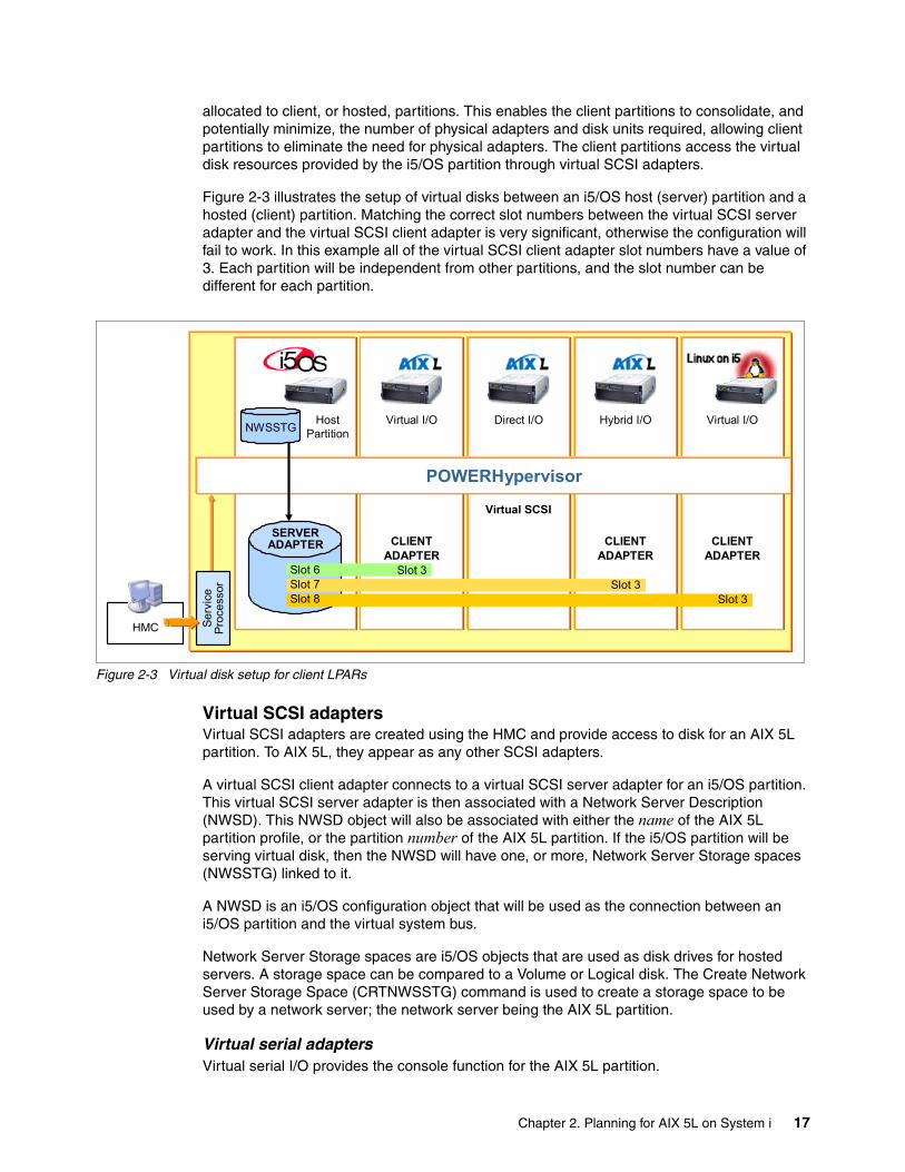
Figure 2-3 illustrates the setup of virtual disks between an i5/OS host (server) partition and a hosted (client) partition. Matching the correct slot numbers between the virtual SCSI server adapter and the virtual SCSI client adapter is very significant, otherwise the configuration will fail to work. In this example all of the virtual SCSI client adapter slot numbers have a value of 3. Each partition will be independent from other partitions, and the slot number can be different for each partition.
Figure 2-3 Virtual disk setup for client LPARs
Virtual SCSI adaptersVirtual SCSI adapters are created using the HMC and provide access to disk for an AIX 5L partition. To AIX 5L, they appear as any other SCSI adapters.
A virtual SCSI client adapter connects to a virtual SCSI server adapter for an i5/OS partition. This virtual SCSI server adapter is then associated with a Network Server Description (NWSD). This NWSD object will also be associated with either the name of the AIX 5L partition profile, or the partition number of the AIX 5L partition. If the i5/OS partition will be serving virtual disk, then the NWSD will have one, or more, Network Server Storage spaces (NWSSTG) linked to it.
A NWSD is an i5/OS configuration object that will be used as the connection between an i5/OS partition and the virtual system bus.
Network Server Storage spaces are i5/OS objects that are used as disk drives for hosted servers. A storage space can be compared to a Volume or Logical disk. The Create Network Server Storage Space (CRTNWSSTG) command is used to create a storage space to be used by a network server; the network server being the AIX 5L partition.
Virtual serial adaptersVirtual serial I/O provides the console function for the AIX 5L partition.
SERVERADAPTER
HostPartition
Virtual I/O Direct I/O Hybrid I/O Virtual I/O
POWERHypervisor
Virtual SCSI
Slot 6Slot 7Slot 8
CLIENTADAPTER
Slot 3
CLIENTADAPTER
Slot 3
CLIENTADAPTER
Slot 3
Serv
ice
Proc
esso
r
HMC
NWSSTG
Chapter 2. Planning for AIX 5L on System i 17

Virtual CDA virtual CD may be used for the installation of AIX 5L 5.3.0.30, or newer. By default, an AIX 5L partition can see all the CD drives on the host i5/OS partition.
Virtual tapeCurrently, AIX 5L does not support virtual tape drives.
2.2 Direct I/O scenarioAn AIX 5L partition can be created using its own dedicated I/O hardware. This is direct I/O.
The partition can have its own LAN, disk and DVD/Tape Input Output Adapters (IOA). Unlike an i5/OS partition, these IOAs do not require an Input Output Processor card (IOP) to drive them.
For the list of supported IOAs on System i, refer to the “AIX 5L Facts and Features” document which can be accessed at:
http://www.ibm.com/servers/eserver/iseries/aix/getting_started.html
Ethernet support on the system unitThe system units of the models 520, 550 and 570 have a built-in pair of Ethernet ports. They are 1 Gbps/10 Mbps/100 Mbps Ethernet ports, and cannot be separated between partitions, they are allocated as a pair.
USB support on the system unitThe system units of the models 520, 550 and 570 have a built-in pair of USB ports. They are supported by AIX 5L and not i5/OS. They cannot be separated between partitions, they are allocated as a pair.
Direct diskAIX 5L on System i can utilize i5/OS disk units, in addition to the AIX 5L/Linux only disk units in the following list.
Disk features for direct I/O disks for AIX 5L and Linux partitionsThe required format of a directly attached disk unit, to install AIX 5L /Linux on, is 512 bytes per sector, and include the following disk unit features codes:
� 1893 - 36.4 GB 10K rpm Disk Unit� 1894 - 73.4 GB 10K rpm Disk Unit� 1895 - 146.8 GB 10K rpm Disk Unit� 1896 - 36.4 GB 15K rpm Disk Unit� 1897 - 73.4 GB 15K rpm Disk Unit� 1898 - 146.8 GB 15k rpm Disk Unit
The direct disk units for an AIX 5L partition are separate from i5/OS partitions, therefore backup and disk protection methods from the AIX 5L partition will be required.
Using i5/OS specific disk units for AIX 5L partitionsWhen using i5/OS specific disk units for AIX 5L, it is necessary to account for existing RAID controllers and/or RAID cache adapters.
Attention: These disk units are not supported for use by i5/OS.
18 AIX 5L on the IBM System i Platform: Implementation Guide

Any i5/OS specific disk units that are attached to hardware RAID controllers, should not be reformatted from 522 bytes/sector to 512 bytes/sector. Doing so will disable any, and all, hardware cache for the DASD controller. This will result in a significant performance degradation for the AIX 5L partition.
This is covered in more detail in 4.2.1, “Configuration of Direct I/O disk units” on page 80.
2.3 Planning for virtual I/OThis section provides information in terms of planning the AIX 5L implementation using virtual I/O.
2.3.1 AIX 5L Virtual I/O Server (VIOS) overviewThe Advanced POWER Virtualization feature of AIX 5L, provides both Virtual I/O Server (VIOS) and Partition Load Manager (PLM) capability. The Virtual I/O Server is a special-purpose partition that provides virtual I/O resources to AIX 5L and Linux client partitions. The Virtual I/O Server owns the resources that are shared with clients. A physical adapter assigned to a partition can be shared by one or more client partitions, enabling administrators to minimize the number of physical adapters they require for individual clients. The Virtual I/O Server helps reduce costs by eliminating the need for dedicated network adapters, disk adapters, and disk drives.
The PLM provides automated processor and memory distribution between client dynamic LPARs and micro-partition-capable LPARs running the AIX 5L operating system. The PLM application is based on a client/server model for the sharing of system information, such as processor or memory events, across concurrent present LPARs.
This book will not explore the Virtual I/O Server. Refer to the IBM Redbooks publication for detailed information about Virtual I/O Server (VIOS):
� Advanced POWER Virtualization on IBM System P5, SG24-7940.
2.3.2 Considerations for virtual I/O scenariosWith virtual I/O, the resources are owned and managed by an i5/OS partition that is hosting an AIX 5L partition. The i5/OS partition shares these resources (disk, CD-ROM, and so on) with the hosted AIX 5L server. The i5/OS provides the DASD protection and some backup/restore facilities for the AIX 5L environment. Virtual Ethernet provides 1 Gb communications paths between logical partitions without requiring additional hardware resources.
The AIX 5L partition is started from the hosting i5/OS partition by varying on the network server description (NWSD). This AIX 5L server can only be active when the i5/OS hosting partition is active. If the i5/OS hosting partition is in restricted state, then the NWSDs are in a varied off state, and the hosted AIX 5L partition will be shutdown.
The advantage of virtual I/O is that you do not need any dedicated hardware for the AIX 5L partition, virtual Ethernet is both a secure and fast way of communicating, and the AIX 5L virtual disk drives can be backed up by a backup procedure on the i5/OS partition.
Chapter 2. Planning for AIX 5L on System i 19

2.3.3 Hardware requirements for a hosted AIX 5L partitionThis section provides information about the minimum hardware requirements as well as supported devices for an AIX 5L partition on the System i platform in which the AIX 5L partition will be using all virtual resources.
Minimum configuration requirementsThe following requirements are for AIX 5L 5.3.0.30, or newer, on the System i platform.
Each AIX 5L partition requires the following minimum hardware resources:
� Processor unit
– A whole processor, if you configure the partition with dedicated option– 0.1 processing unit, if you configure the partition with shared option
� Memory
– Minimum 128 MB of memory
� Disk storage
– One virtual storage adapter (VSCSI) for virtual I/O– Minimum 2.2 GB of disk storage
� Network interface
– One virtual Ethernet adapter for virtual I/O
Communication optionsAIX 5L on a System i can establish a TCP/IP connection through either a directly attached network adapter or through a virtual Ethernet adapter. In a virtual I/O scenario, we are using a virtual Ethernet adapter.
Virtual network adaptersVirtual Ethernet provides the same function as using a 1 Gb Ethernet adapter. i5/OS and AIX 5L partitions on a System i can communicate using TCP/IP over the virtual Ethernet communication ports. Virtual Ethernet provides a very high speed, secure mechanism for communication among partitions on a single physical system.
Supported hardware resourcesThis section lists the devices and adapters supported at the time of the writing of this book. For up to date information, refer to the IBM eServer Hardware Information Center at:
http://publib.boulder.ibm.com/infocenter/eserver/v1r3s/index.jsp
Virtual devicesAIX 5L on System i supports virtual devices, as illustrated in Table 2-1.
Table 2-1 Virtual devices
Note: In addition to these minimum hardware requirements, you also need to apply all critical fixes and updates for the HMC, firmware, and i5/OS.
Device In AIX 5L work as In i5/OS work as
Virtual console Server Client
Virtual CD Client Server
Virtual SCSI Client Server
20 AIX 5L on the IBM System i Platform: Implementation Guide

Note:*Virtual Ethernet works as peer-to-peer communication.
2.4 Planning for direct I/OThis section provides information in terms of planning an AIX 5L implementation using direct I/O.
2.4.1 Considerations for direct I/O scenariosAIX 5L is able to communicate directly with System i hardware, such as disk units, Ethernet adapters, tapes, and so on. Such a scenario is called direct I/O scenario. Direct I/O means that I/O resources allocated to an AIX 5L partition are owned by, and are under the control of, said AIX 5L partition. It is not dependent on an i5/OS partition for any of its resources. Consequently, no i5/OS partition can use these resources, because they are allocated to the AIX 5L partition. For directly attached hardware, all failure and diagnostic messages are managed by the AIX 5L partition.
With direct I/O, an AIX 5L partition will be completely independent of any i5/OS partitions. It can be active when other partitions are not active, which is not the case in a virtual I/O scenario. Direct I/O will also allow the use of a tape drive by an AIX 5L partition.
The disadvantage of direct I/O is that it demands more hardware administration.
2.4.2 Hardware requirements for an AIX 5L logical partition This section provides the information about the minimum hardware requirements for a direct I/O configuration, as well as supported devices for AIX 5L on System i.
Minimum configuration requirementsEach AIX 5L partition requires the following minimum hardware resources:
� Processor unit
– A whole processor if you configure the partition with dedicated option– 0.1 processing unit if you configure the partition with shared option
� Memory
– Minimum 128 MB GB of memory
� Disk storage
– One physical IOA for native I/O– One hard disk (at least 2.2 GB)
� Network interface
– One physical NIC (Network Interface Card) for native I/O
Virtual serial Client Client
Virtual Ethernet N/A* N/A*
Device In AIX 5L work as In i5/OS work as
Note: In addition to these minimum hardware requirements, you also need to apply all critical fixes and updates for the HMC and firmware.
Chapter 2. Planning for AIX 5L on System i 21

Communication optionsAIX 5L on System i can establish a TCP/IP connection through either a directly attached network adapter or through a virtual Ethernet adapter. In a direct I/O scenario, we are using directly attached network adapters.
Directly attached network adaptersAn AIX 5L partition can have physical Ethernet adapters allocated to it. If you have multiple Ethernet adapters, you might consider dedicating one or more to the AIX 5L partition. A dedicated adapter eliminates the extra step involved in using the virtual Ethernet to communicate with the network as routing methods. You can even limit the traffic between partitions.
Supported hardware resourcesThis section lists the devices and adapters supported at the time of writing of this book. For up to date information, refer to IBM eServer Hardware Information Center at:
http://publib.boulder.ibm.com/infocenter/eserver/v1r3s/index.jsp
Network adaptersTable 2-2 lists the network adapters supported by AIX 5L on System i for native I/O, or directly attached option.
Table 2-2 Network adapters supported for native I/O AIX 5L partition
Description AIX 5L Feature Number
i5/OS Feature Number
Systems/ Expansion Units
Adapter specifics
Additional information
PCI-X 1 Gb Ethernet-SX Fiber
0620/6800
5700 520, 550, 570, 595
Short, 32 or 64-bit, 3.3 or 5V
High bandwidth
PCI-X 10/100/1 G Base-TX Ethernet
0621/6801
5701 520, 550, 570, 595
Short, 32 or 64-bit, 3.3 or 5V
High bandwidth
PCI-X 10/100/1 G 2-port Base-TX Ethernet
5706 5706 520, 550, 570, 595
Short, 32 or 64-bit, 3.3 or 5V
High bandwidth
PCI-X 1 Gb 2-port Ethernet-SX Fiber
5707 5707 520, 550, 570, 595
Short, 32 or 64-bit, 3.3 or 5V
High bandwidth
100/10 Mbps 4-port Ethernet
0637 570, 595 long, 32 or 64-bit, 3.3 or 5V
IBM 2-Port 10/100/1000 Base-TX Ethernet
0643 520, 550, 570, 595
Short, 32 or 64-bit, 3.3 or 5V
High bandwidth
IBM 2-Port Gigabit Ethernet-SX
0644 520, 550, 570, 595
Short, 32 or 64-bit, 3.3 or 5V
High bandwidth
IBM Token-Ring PCI Adapter
4959 520, 550, 570, 595
Short, 32-bit, 3.3 or 5V
22 AIX 5L on the IBM System i Platform: Implementation Guide

10/100 Mbps Ethernet PCI Adapter II
4962 520, 550, 570, 595
Short, 32-bit, 3.3 or 5V
10 Gigabit Ethernet PCI-X Adapter
5718 520, 550, 570, 595
Short, 32 or 64-bit, 3.3 or 5V
High bandwidth
10 Gigabit ENET (Fiber)
5719 520, 550, 570, 595
Short, 32 or 64-bit, 3.3 or 5V
High bandwidth
10 Gigabit Ethernet (short reach)
5721 573A 520, 550, 570, 595
Short, 64-bit, 3.3V
High bandwidthRecommended in DDR slot
10 Gbps Ethernet (long reach)
5722 576A 520, 550, 570, 595
Short, 64-bit, 3.3V
4-Port 10/100/1000 Base-TX
5740 5740 520, 550, 570, 595
Short, 64-bit, 3.3V
High bandwidth
Description AIX 5L Feature Number
i5/OS Feature Number
Systems/ Expansion Units
Adapter specifics
Additional information
Chapter 2. Planning for AIX 5L on System i 23

Storage adaptersTable 2-3 lists the storage adapters supported by AIX 5L on System i for native I/O, or directly attached.
Table 2-3 Storage adapters supported for native I/O AIX 5L partition
Other disk controllers and magnetic media adaptersTable 2-4 lists additional disk controllers and magnetic media adapters supported by AIX 5L on System i for native I/O or directly attached option.
Table 2-4 Additional disk controller and magnetic media adapters supported: direct I/O AIX 5L partition
Description AIX 5L Feature Number
i5/OS Feature Number
Systems/ Expansion Units
Adapter specifics
Additional information
Dual Channel Ultra320 SCSI RAID and Dual Channel Ultra320 SCSI RAID Blind Swap
0628 5703, 5711
520, 550, 570, 595
Long, 32 or 64-bit, 3.3V
High bandwidth
32 MB Planar Dual Channel SCSI RAID Enablement
5709 5709 520, 550, 570
Custom slot
PCI Dual Channel Ultra3 SCSI Adapter
6203 570 Long, 32 or 64-bit, 3.3 or 5V
Dual Channel Ultra320 SCSI Blind Swap and Dual Channel Ultra320 SCSI
0645 5710, 5712
520, 550, 570, 595
Short, 32 or 64-bit, 3.3V
High bandwidth
PCI Ultra™-3 RAID Adapter
0642 520, 570 Long, 32 or 64-bit, 3.3 or 5V
High bandwidth
PCI Universal Differential Ultra SCSI
6204 520, 550, 570, 595
Short, 32-bit, 3.3 or 5V
PCI Fibre Channel Disk Controller
0612 2766
PCI-X U320 RAID w/Read Cache
0627 2780 520, 550, 570, 595
Long, 64-bit, 133MHz
High bandwidthThis feature is not supported in slot 1 of models 5074, 5079, 5094, and 5294
PCI-X Fibre Channel Disk Controller
5760 280E 520, 550, 570, 595
Short, 32 or 64-bit, 3.3V
High bandwidth
Description AIX 5L Feature Number
i5/OS Feature Number
Systems/ Expansion Units
Adapter specifics
Additional information
Direct Attach - 2765: PCI 2 Gb Fibre Channel Tape Controller
0611 2765 520, 550, 570, 595
Short, 64-bit, 66MHz
High bandwidth
24 AIX 5L on the IBM System i Platform: Implementation Guide

WAN adaptersTable 2-5 lists the WAN adapters supported by AIX 5L on System i for native I/O, or directly attached option.
Table 2-5 WAN adapters supported for direct I/O AIX 5L partition
Direct Attach - 5704 0625 5704 520, 550, 570, 595
Short, 32 or 64-bit, 3.3V
High bandwidth
Advanced Serial RAID Plus
0638 570 Short, 32 or 64-bit, 3.3 or 5V
High bandwidth
2 Gigabit Fibre Channel Adapter
0646 5716 520, 550, 570, 595
Short, 32 or 64-bit, 3.3 or 5V
High bandwidth
Direct Attach - 5736: Dual Channel Ultra320 SCSI
0647 571A 520, 550, 570, 595
Short, 32 or 64-bit, 3.3V
High bandwidthEEH supported
Direct attach - 5736: Dual Channel Ultra320 SCSI RAID
0648 571B 520, 550, 570, 595
Long, 32 or 64-bit, 3.3V
High bandwidthEEH supported
ISCSI TOE Gigabit (Copper)
5713 520, 550, 570, 595
Short, 32 or 64-bit, 3.3 or 5V
High bandwidth
ISCSI TOE Gigabit (Fiber)
5714 520, 550, 570, 595
Short, 32 or 64-bit, 3.3 or 5V
High bandwidth
CPCI-X Tape/DASD Unit controller
5715 5702 520, 550, 570, 595
Short, 32 or 64-bit, 3.3V
Direct Attach - 5704 5758 280D 520, 550, 570, 595
Short, 32 or 64-bit, 3.3V
High bandwidth
PCI-X Fibre Channel Tape Controller
5761 280D 520, 550, 570, 595
Short, 32 or 64-bit, 3.3V
High bandwidth
Description AIX 5L Feature Number
i5/OS Feature Number
Systems/ Expansion Units
Adapter specifics
Additional information
HSL-2/RIO-G 2-Ports Copper
7818 595 Custom slot 2 port RIO-G (copper) bus adapter for 595
HSL/RIO 2-Ports Optical
7819 595 Custom slot 2 port RIO-G (optical) bus adapter for 595
PCI Two-Line WAN
6805 2742 520, 550, 570, 595
Short
PCI 2-line WAN/Modem
9771 2771 520, 550, 570, 595
Short, 32-bit, 3.3 or 5V
Only one per system
PCI Two-Line WAN w/Modem
6803 2793 520, 550, 570, 595
Short Non-CIM
Description AIX 5L Feature Number
i5/OS Feature Number
Systems/ Expansion Units
Adapter specifics
Additional information
Chapter 2. Planning for AIX 5L on System i 25

2.5 Planning for networkThe System i platform supports the allocation of both virtual and native network adapters to a partition (in fact both types of adapters can be allocated to the same partition). With virtual network adapters, network packets are “copied” between the memory allocation of the partitions by the hypervisor and provides for very fast, reliable, and secure communications between partitions. Information about how network traffic can be forwarded between a virtual and physical network is discussed in Chapter 5, “Network configuration” on page 91.
There are a number of considerations for determining the allocation of network adapters to an AIX 5L partition. These considerations include the following:
� Requirements for fast intra-partition access (such as ODBC to DB2/400).
� Requirement for external (that is, outside the System i platform) access to the AIX 5L partition.
� Requirement for direct access by the AIX 5L partition to network traffic.
While the assignment of virtual and physical network adapters will be very dependent on the environment, as well as the availability of system resources, some general recommendations can be made:
– AIX 5L partitions that are going to perform firewall functions should have a physical network adapter allocated to it for the external traffic, and one or more virtual network adapters for routing authenticated traffic to other partitions.
– A partition that is going to impose significant network traffic between itself and another partition (such as an AIX 5L partition running the Apache Web server accessing DB2/400 data via ODBC) should implement virtual network adapters in both partitions to ensure that the traffic is passed at the gigabit speed provided by the virtual LAN.
2.6 Planning for hybrid: Virtual and direct I/O mixedThe most common configuration scenario is a hybrid, or mixture, of virtual I/O and direct I/O.
PCI Two-Line WAN w/Modem (CIM)
6804 2793 520, 550, 570, 595
Short CIM
PCI Quad Modem
6808 2805 520, 550, 570, 595
Long Non-CIM
PCI Quad Modem (CIM)
6809 2805 520, 550, 570, 595
Long CIM
Quad Digital Trunk Telephony
6312 520, 550 Long, 32 or 64-bit, 3.3 or 5V
Digital Trunk adapters have internal cable, requires continuos slots.
Description AIX 5L Feature Number
i5/OS Feature Number
Systems/ Expansion Units
Adapter specifics
Additional information
26 AIX 5L on the IBM System i Platform: Implementation Guide
2.6.1 All direct I/O except virtual CD/DVDThis scenario will be used when the System i has one CD/DVD drive, and/or it does not have a CD/DVD drive that can be directly accessed by AIX 5L. This may also be used if you want to make a CD/DVD drive available to multiple partitions.
2.6.2 Direct network adapter and virtual storageThis scenario is the most common implementation. An i5/OS partition will provide virtual disk drives to an AIX 5L client partition, and the AIX 5L partition will also have physical Ethernet adapter(s) allocated to it.
2.6.3 Direct storage and virtual LANThis scenario is possible, but unlikely. An AIX 5L partition will have a SCSI controller allocated to it, but no Ethernet adapter(s). Instead, a virtual LAN adapter is configured, along with a virtual LAN adapter for an i5/OS partition, and both adapters are configured for the same VLAN ID. The i5/OS partition is then configured to use Proxy ARP or NAT to route network traffic to the virtual LAN adapter for the AIX 5L partition.
2.7 Current considerations of AIX 5L on System iThe LPAR Validation Tool has been replaced with the System Planning Tool. We recommend the use of this tool to optimally configure your system i for all Operating Systems you plan to utilize. For more detailed information about the System Planning Tool, refer to this IBM Redbooks publication:
� LPAR Simplification Tools Handbook, SG24-7231
An important feature of this tool is the capability to save a complete system configuration as a sysplan, which can be imported into an HMC, to automatically create the partition configurations.
2.7.1 Virtual I/O considerationsUsing virtual I/O will leave any AIX 5L client partitions completely dependent upon the host i5/OS partition. The client partitions are usually started by the host i5/OS partition, and only after it has started.
Virtual optical devices configured in an i5/OS partition will be made available to a client AIX 5L partition. However they are not easily identified from AIX 5L.
Currently, AIX 5L 5.3 does not support virtual tape devices.
2.7.2 Direct I/O considerationsThis configuration scenario will require sufficient pre-planning, and system review. Since AIX 5L does not use Input Output Processors (IOP), the hardware resources to be allocated cannot be under, or downstream an IOP.
2.7.3 Virtual and direct I/O hybrid considerationsThese configuration scenarios will require a combination of both direct I/O and virtual I/O, so they will be more complex.
Chapter 2. Planning for AIX 5L on System i 27

28 AIX 5L on the IBM System i Platform: Implementation Guide

Chapter 3. Partition configuration
This chapter reviews the process to create logical partitions on the System i platform. It also provides the step-by-step guide of creating a logical partition on the System i platform for AIX 5L server.
3
© Copyright IBM Corp. 2005. All rights reserved. 29

3.1 Concepts and terminologyHere are concepts and terms you need to know when creating the Logical partition on the System i platform for the AIX 5L instance.
Logical partitionsBy using logical partitioning (LPAR), a single physical system can be divided into multiple logical partitions each running their own operating system image.
LPAR provides a framework for systems consolidation on System i servers.
Partition IDThe partition ID is a whole number used to identify logical partitions.
Partition profileA partition profile specifies the resources and settings for a logical partition. This includes the memory, processor and I/O allocations. To activate a logical partition, one of the partition profiles for that logical partition must be activated.
You may have multiple partition profiles with different resource specifications for a single logical partition based on the needs/requirements of that logical partition. Note, however, that only one partition profile can be active at a time. Activating a different partition profile requires the logical partition to be shutdown.
If you have multiple partition profiles, any one of them can be designated as the default partition profile. The HMC will activate the default profile unless you specify a different partition profile to be activated.
It is possible that a partition profile will not activate due to an over commitment of resources on the system. The HMC shows all of the resources available on the system but does not verify if these resources are already in use by an activated partition profile. As a partition profile is activated, the system attempts to allocate the resources specified. If the resources are already in use, the partition profile will not activate.
Minimum, desired, maximum valuesAs you setup the partition profile, you will be asked to input the minimum, desired, and maximum values for memory and processor units. If your system resources are not overcommitted, the logical partition will get the desired values. However, if resources are overcommitted, the logical partition will be given a value between the minimum and desired values. If the minimum value cannot be met, the partition profile will not activate, meaning you cannot start the particular server, that is, operating system, of that partition. The maximum indicates the maximum value that may be dynamically set.
Full system partition profileA full system partition profile is a partition profile that has been setup to use all the resources of the system including memory, processors, I/O, disks. A full system partition profile can be used for i5/OS only.
When this partition profile is activated, all system resources are committed to the associated logical partition. No other partition profiles and logical partitions will be allowed to be activated as long as this full partition profile and associated logical partition are active. Conversely, a full system partition profile cannot be activated when other partition profiles and logical partitions are already active.
30 AIX 5L on the IBM System i Platform: Implementation Guide
If additional hardware resources are added to the system and then a full system partition profile is activated, the associated logical partition automatically recognizes and uses the new hardware.
A note of warning: Because all the disks are allocated to this full system partition profile, the logical partition may overwrite the disk resources on the system.
System profileA system profile is an ordered list of partition profiles on the managed system. When a system profile is activated, the managed systems will attempt to activate the partition profiles in the order they are listed in the system profile.
A system profile is helpful when changing the managed system from one set of logical partitions to another.
It is possible to create a system profile that contains a partition profile with overcommitted resources. The HMC can be used to validate the system profile against currently available resources or against the total system resources. This validation will ensure your I/O devices and processing resources are not overcommitted. However, memory requirements are only estimated. It is possible for a system profile to pass the validation test, but not have enough memory to be activated.
Service partitionThe HMC reports hardware errors to IBM. If the HMC is unavailable, then a service partition can report errors. This partition has the authority needed to update the system and other policy parameters without having to power off the System i. On System i systems, only an i5/OS logical partition can act as the service partition. This service partition typically has a physical connection to a network attached to the HMC and virtual connections to the other logical partitions on the System i. This allows the service partition to receive server errors from the other logical partitions and report the server errors to IBM.
3.2 Verify available resourcesBefore starting the wizard to create a partition in HMC, verify that required resources are available:
� CPU� Memory� Any direct I/O adapters that will be needed for AIX 5L, if necessary.� Virtual I/O at host i5/OS partition
To verify this on HMC, right-click the Managed System and select Properties as shown in Figure 3-1 on page 32.
Chapter 3. Partition configuration 31

Figure 3-1 Managed system properties selection
Click the Processors tab to receive detailed managed system processor information, as shown in Figure 3-2.
Figure 3-2 Managed system properties - Processors
As this example shows, there are two processors on the Managed System, with 0.50 processor units currently allocated to an AIX 5L partition, and 1.0 processor units allocated to a single i5/OS logical partition. This leaves 0.50 processor units that can be allocated to additional logical partitions.
Number of virtual processors
Once the amount of processor resource has been determined, the number of virtual processors to spread the workload across needs to be determined. A virtual processor can
32 AIX 5L on the IBM System i Platform: Implementation Guide

be thought of as a manifestation of a processor and is represented to the operating system as a processor thread. The number of virtual processors to allocate to a logical partition can be affected by a number of factors including:
� Type of workload� Amount of processor allocation� Number of physical processors in the system
There are certain workloads, such as database, that can benefit from a large number of processor threads; however, most workloads that are implemented on the System i platform do not require a large number of processor threads. Each processor thread that will be allocated to a logical partition requires at least 1/10th of a processor unit allocated to the partition. Additionally, no more than a full processor (that is, 1.00 processor units) can be allocated to a single processor thread. Put another way, if 4.20 processor units are allocated to a partition then the minimum number of virtual processors that can be allocated is 5 while the maximum number of virtual processors that can be allocated is 42.
As a general rule for AIX 5L partitions, the number of virtual processors allocated will be the least amount required by the allocation of processor units to the platform.
Capped/Uncapped settingThe system i platform provides the ability for the system to balance the allocation of processor resources across the system based upon the active workloads. This is referred to as “uncapped” partitions.
MemoryMemory is allocated to the logical partitions on the System i platform from the overall memory installed in the system. The amount of memory to allocate to an AIX 5L partition is directly dependent on the workload that will be implemented in the AIX 5L partition as well as the type of I/O (that is, virtual or native) that will be allocated to the AIX 5L partition.
For each partition on the Managed System, the hypervisor will set aside memory resources to manage the memory addressing for the partition. This memory is referred to as the Hardware Paging Table (HPT). The size of the HPT is based on the maximum memory definition for the partition and provides a set of offsets from the partitions memory address to the physical memory of the system. The size of the HPT can be calculated by taking the maximum memory definition for the partition, dividing that figure by 64 and then rounding to the next power of 2.
When a partition leverages I/O resources hosted by another partition (that is, an i5/OS partition hosting resources for an AIX 5L partition), memory resources are required in the hosting partition to process the I/O requests from the guest partition. Put another way, for each guest partition hosted by i5/OS, consideration for the amount of memory allocated to the i5/OS partition needs to be made. The amount of additional memory required in the hosting partition will vary based on the I/O footprint of the hosted (guest) partition(s).
The current memory allocation on the Managed System can be reviewed through the properties of the Managed System.
1. From the Managed System Property Dialog, select the Memory tab to display the memory allocation on the Managed system.
Note: Most AIX 5L partitions on the System i platform are configured as uncapped partitions, and AIX 5L 5.3 requires a minimum of 0.10 shared processor units and 1 virtual CPU.
Chapter 3. Partition configuration 33

2. The memory allocation (as shown in Figure 3-3) reflects the overall memory installed in the Managed System less the amount of memory allocated to each active partition as well as memory set aside for the Hardware Paging Tables and overhead for hypervisor overhead.
Figure 3-3 Managed system properties - Memory Allocation
3.3 Initial partition settingsThis section will be applicable to all possible I/O scenarios. The following steps need to be done to create a new partition on a System i If already familiar with this process, you may skip ahead to 3.4, “I/O settings for virtual I/O” on page 44 for Virtual I/O configuration.
3.3.1 Create the logical partitionThis section provides step-by-step guidelines of creating the logical partition.
Note: AIX 5L Version 5.3 system requires:
� A minimum of 128 MB of physical memory� A minimum of 2.2 GB of physical disk space
For more information refer to AIX 5L Version 5.3 Release Notes, which can be accessed at:
http://publib.boulder.ibm.com/infocenter/pseries/v5r3/index.jsp?topic=/com.ibm.aix.resources/53relnotes.htm
34 AIX 5L on the IBM System i Platform: Implementation Guide

Create a new AIX 5L partition1. In the navigation area of the HMC, select Server and Partition → Server Management.
Then in the right-hand contents pane, right-click Partitions and select Create → Logical partition as illustrated in Figure 3-4.
Figure 3-4 Start Logical Partition Wizard
2. At this point the Partition wizard appears. The Partition ID is an integer number that is used by the system to uniquely identify the partition and typically is left at the default value displayed. You need to provide the partition name and specify that the Partition environment is AIX or Linux as illustrated in Figure 3-5. Once the fields have been completed click the Next button to continue.
Figure 3-5 Creating a new partition
Chapter 3. Partition configuration 35

3. This next window provides you the option for the partition to be a part of a group of partitions that can be managed by a workload application. We choose No, as illustrated in Figure 3-6. Click Next to continue.
Figure 3-6 Creating a new partition - workload
4. The next step is creating a partition profile. A partition profile specifies characteristics of the partition, such as the memory, processors, physical and virtual adapters.
As illustrated in Figure 3-7, give the name of the profile. In our example, we use the profile name AIX. Click Next to continue.
Figure 3-7 Creating a new partition - Logical Partition Profile
36 AIX 5L on the IBM System i Platform: Implementation Guide

5. Next, we specify the memory size that the partition profile will manage, as illustrated in Figure 3-8. Use this page to specify the memory management information for this partition profile. You must specify three memory levels:
– The minimum memory is the minimum amount of memory that the logical partition must have to start up. If the system cannot allocate this much memory, the activation of this partition will fail.
– The desired memory is the amount of memory that you want the logical partition to have when you activate the logical partition.
– The maximum memory is the maximum amount of memory that the logical partition is allowed to have when you dynamically move memory.
When the partition is activated, an attempt will be made to allocate the "desired" amount of memory defined for the partition-profile; if the amount of desired memory is not available, then an additional check will be made to see if the amount of unallocated memory left on the Managed System is more than or equal to the "minimum" amount of memory defined for the partition profile. If the amount of memory is equal to or greater than the minimum defined memory, then it will be allocated to the partition; otherwise, the partition will fail to activate.
Figure 3-8 Creating a new partition - Memory
In our example, the minimum quantity of memory that the partition will be activated with is 128 MB, the desired amount of memory is 512 MB and the maximum amount of memory is 1.5 GB. Click Next to continue.
6. The next step is to choose Shared or Dedicated processors. Dedicated means you are not sharing the processor with other partitions. With the Shared option, you can utilize the subprocessor feature where each partition can run with 0.1 processing unit at minimum. While the minimum processor (for shared) is 0.10, the definition can be in the hundredths of processor units (for example, 0.15). This is referred as micro-partitioning. In our example, we choose the Shared option, as illustrated in Figure 3-9 on page 38.
Note: In addition to the memory allocated to the partition, the hypervisor sets aside memory to manage the partitions memory. This additional memory is called the Hardware Paging Table and is based on the size of the maximum memory setting.
Chapter 3. Partition configuration 37

Figure 3-9 Creating a new partition - Processor
7. For the Shared processor option, we choose the minimum, maximum, and desired processing units of the partition.
When the partition is activated, an attempt will be made to allocate the "desired" amount of processors defined for the partition-profile; if the amount of desired processors is not available, then an additional check will be made to see if the amount of unallocated processors left on the Managed System is more than or equal to the "minimum" amount of processors defined for the partition profile. If the amount of processors is equal to or greater than the minimum defined processors, then it will be allocated to the partition; otherwise, the partition will fail to activate.
As illustrated in Figure 3-10, we define 0.1 unit of a processor to be our minimum processing units, 1 unit of processor power as our desired amount, and 1.5 as the maximum processing units. Click the Advanced button.
Figure 3-10 Creating a new partition - Processing Units
8. When shared processing units are defined in a partition profile, additional settings can be set for the number of virtual processors as well as the capped/uncapped setting. As shown in Figure 3-11 on page 39, the sharing mode can be set to either Capped or Uncapped.
38 AIX 5L on the IBM System i Platform: Implementation Guide

An uncapped partition will have the ability to have additional processing units allocated to it by the hypervisor on an as needed basis, based on the performance of the overall system. Capped partitions will only have access to the processing units allocated to it when first started (or changed through Dynamic Logical Partitioning - DLPAR).
For uncapped partitions a weight will be specified that indicates the ratio of left over (or surplus) processing units that will be allocated to the partition. As an example, if two partitions are configured as uncapped with a weight of 10 and 20 respectively and both are busy, then the partition with a weight of 20 will get two thirds of the surplus processor resource while the partition that has a weight of 10 will get one third of the surplus processor resource.
In addition to the sharing mode, the number of virtual processors is also defined through the Advanced Processing Settings page. The number of virtual processors indicates the number of processor threads that the workload allocated processing units will be spread across.
In this example, we set the sharing mode of the partition to uncapped with a weight of 128 and set the number of virtual processors to a minimum of 1, desired of 1 and a maximum of 2. Once the values have been set, click OK, and then click Next on the Create Logical Partition Profile - Processing Settings window.
Figure 3-11 Creating a new partition - Advanced Processing Settings
9. The next dialog displayed (Figure 3-12 on page 40) is for the allocation of physical hardware to the partition. As illustrated in, the window displays the hardware installed in the managed system and allows for selection of hardware for the partition profile. Hardware resource allocation will be covered in detail in 4.2, “Direct I/O” on page 80 for storage device allocation and 5.1.1, “AIX 5L physical network adapter allocation” on page 92 for network adapter allocation.
Chapter 3. Partition configuration 39

Figure 3-12 Creating a new partition - I/O hardware selection
10.The next window, illustrated in Figure 3-13 on page 41, is for adding the I/O pools. AIX 5L partitions do not use I/O Pools, so click Next to continue.
40 AIX 5L on the IBM System i Platform: Implementation Guide

Figure 3-13 Creating a new partition - I/O Pools selection
11.The next dialog displayed (Figure 3-14) is for Virtual I/O Adapter allocation. Virtual I/O adapter allocation will be covered in detail in 3.4.3, “Virtual I/O definitions in AIX 5L partition profile” on page 47.
Figure 3-14 Creating a new partition - Virtual I/O selection
.
12.The next dialog displayed is for the definition of a Power Controlling partition.
Note: Virtual I/O adapter allocation will be covered in detail in 3.4.3, “Virtual I/O definitions in AIX 5L partition profile” on page 47.
Chapter 3. Partition configuration 41

A Power Controlling partition is a partition that is allowed to make power requests (activate, shutdown) for a partition via the hypervisor. Figure 3-15 shows the definition window for the Power Controlling partition.
This is usually configured when utilizing virtual I/O. When using virtual I/O, the host partition is defined as the Power Controlling partition of the hosted partition, and will be covered in more detail in 3.4.3, “Virtual I/O definitions in AIX 5L partition profile” on page 47.
Figure 3-15 Creating a new partition - Power Controlling partition
13.The next dialog displayed (Figure 3-16 on page 43) is for Boot mode configuration. This will need to be configured for System Management Services (SMS) to install AIX 5L to a partition using virtual disk and/or from a virtual CD/DVD.
Refer to 3.4.3, “Virtual I/O definitions in AIX 5L partition profile” on page 47 for more detailed information about virtual I/O, and 6.1, “New virtual CD-ROM installation process” on page 122 for information about using virtual CD/DVD for installation.
42 AIX 5L on the IBM System i Platform: Implementation Guide

Figure 3-16 Creating a new partition - Boot modes
14.The next, and final, dialog displayed is the Profile Summary. At this point the partition definition is complete and the a summary of the definition is displayed as shown in Figure 3-17.
Figure 3-17 Creating a new partition - Profile Summary
Chapter 3. Partition configuration 43
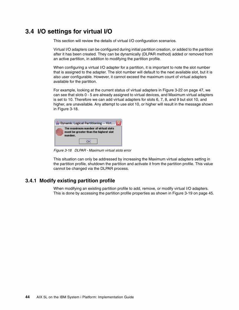
3.4 I/O settings for virtual I/OThis section will review the details of virtual I/O configuration scenarios.
Virtual I/O adapters can be configured during initial partition creation, or added to the partition after it has been created. They can be dynamically (DLPAR method) added or removed from an active partition, in addition to modifying the partition profile.
When configuring a virtual I/O adapter for a partition, it is important to note the slot number that is assigned to the adapter. The slot number will default to the next available slot, but it is also user configurable. However, it cannot exceed the maximum count of virtual adapters available for the partition.
For example, looking at the current status of virtual adapters in Figure 3-22 on page 47, we can see that slots 0 - 5 are already assigned to virtual devices, and Maximum virtual adapters is set to 10. Therefore we can add virtual adapters for slots 6, 7, 8, and 9 but slot 10, and higher, are unavailable. Any attempt to use slot 10, or higher will result in the message shown in Figure 3-18.
Figure 3-18 DLPAR - Maximum virtual slots error
This situation can only be addressed by increasing the Maximum virtual adapters setting in the partition profile, shutdown the partition and activate it from the partition profile. This value cannot be changed via the DLPAR process.
3.4.1 Modify existing partition profileWhen modifying an existing partition profile to add, remove, or modify virtual I/O adapters. This is done by accessing the partition profile properties as shown in Figure 3-19 on page 45.
44 AIX 5L on the IBM System i Platform: Implementation Guide

Figure 3-19 Accessing partition profile properties
This will display the dialog shown in Figure 3-20.
Figure 3-20 Partition profile properties.
From here, the Virtual I/O Adapters section can be accessed. The SCSI Server Adapter will only be available for i5/OS, and VIOS partitions. The i5/OS partitions do not support virtual SCSI client adapters.
When making changes to a partition profile, the changes will not be recognized by an active partition, or hypervisor, until AFTER the next time the partition profile is activated.
Note: A restart of a partition (that is, PWRDWNSYS RESTART(*YES)) does not activate a partition profile, it will use the current partition profile that is resident in hypervisor memory. To properly activate any partition profile changes, the partition must be shutdown, then activated from the partition profile on the HMC.
Chapter 3. Partition configuration 45

3.4.2 DLPAR processIf you are unable to shutdown an active partition to activate any changes made in the partition profile, then your only option is to add the virtual I/O adapter to the running state of the partition through the use of Dynamic Logical Partitioning (DLPAR).
To add the Virtual SCSI Server adapter to the hosting i5/OS partition, right-click the i5/OS partition (not the partition profile) and then select Dynamic Logical Partitioning → Virtual Adapter Resources → Add/Remove as shown in Figure 3-21.
Figure 3-21 Dynamic Logical Partitioning, add/remove Virtual I/O resources
From this display, the partitions current configuration can be determined. As shown in Figure 3-22 on page 47, the display shows the current virtual I/O devices allocated for this partition, and the slot numbers they are allocated to use.
46 AIX 5L on the IBM System i Platform: Implementation Guide
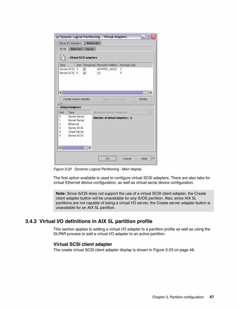
Figure 3-22 Dynamic Logical Partitioning - Main display
The first option available is used to configure virtual SCSI adapters. There are also tabs for virtual Ethernet device configuration, as well as virtual serial device configuration.
3.4.3 Virtual I/O definitions in AIX 5L partition profileThis section applies to adding a virtual I/O adapter to a partition profile as well as using the DLPAR process to add a virtual I/O adapter to an active partition.
Virtual SCSI client adapterThe create virtual SCSI client adapter display is shown in Figure 3-23 on page 48.
Note: Since i5/OS does not support the use of a virtual SCSI client adapter, the Create client adapter button will be unavailable for any i5/OS partition. Also, since AIX 5L partitions are not capable of being a virtual I/O server, the Create server adapter button is unavailable for an AIX 5L partition.
Chapter 3. Partition configuration 47

Figure 3-23 Virtual SCSI client adapter configuration
This display has a significant amount of empty space, so let us focus on the necessary section, Figure 3-24, for adapter configuration.
Figure 3-24 Close up of virtual SCSI client adapter properties
When configuring a virtual SCSI client adapter, take note of the client slot number assigned to the adapter, as well as assigning the correct host i5/OS partition. In the example shown in Figure 3-24, the slot number assigned to this virtual SCSI client adapter is 3, and the host i5/OS partition is RCHAS60_i5.
If the slot number of the virtual SCSI server adapter is already known, then it can be defined at this time as well. If it is not known, and this adapter is being added to a partition profile, then this can be left at the default setting and will need to be changed before the AIX 5L partition is activated. If this adapter is being DLPAR’ed (configured dynamically in a DLPAR
48 AIX 5L on the IBM System i Platform: Implementation Guide

way) into an active partition, then the virtual SCSI client adapter will need to be removed and added again with the correct slot number of the virtual SCSI server adapter.
It is important to understand the cross-over relationship between the virtual SCSI client and server adapters. To help clarify, the Virtual SCSI Client adapter for the AIX 5L partition needs to point to the Virtual SCSI Server adapter for the Hosting i5/OS partition and likewise, the Virtual SCSI Server adapter for the hosting i5/OS partition needs to point to the Virtual SCSI client adapter for the AIX 5L partition.
As an example, look at Figure 3-25 which shows the properties of the virtual SCSI server adapter for the hosting i5/OS partition and mappings to the properties of the virtual SCSI client adapter for the AIX 5L partition.
Figure 3-25 Virtual SCSI adapters - Mapping example
Once the virtual SCSI client adapter settings have been completed, click OK. This will save the client SCSI adapter and put it in the list of adapters.
If this virtual SCSI client adapter will be used to access virtual disk from an i5/OS partition, and the virtual disk will be used as rootvg, then it should be marked as Required, as shown in Figure 3-26 on page 50. Click OK.
Note: If this client adapter is going to be used to access only a virtual CD/DVD from an i5/OS partition, then it is not necessary to mark it as Required.
Virtual SCSI server adapter properties on i5/OS partition
Virtual SCSI client adapter properties on AIX 5L partition
Client slot numbersNeed to match
Server slot numbersNeed to match
Chapter 3. Partition configuration 49

Figure 3-26 Virtual SCSI client adapter - Required
Virtual Ethernet adapterTo define a virtual Ethernet adapter, click the Ethernet tab, and click Create adapter as shown in Figure 3-27 on page 51.
50 AIX 5L on the IBM System i Platform: Implementation Guide

Figure 3-27 Virtual Ethernet selection
This will produce the display shown in Figure 3-28 on page 52.
Chapter 3. Partition configuration 51

Figure 3-28 Virtual Ethernet adapter configuration
Once again there is a significant amount of empty space, so we will focus on the primary configuration area shown in Figure 3-29.
Figure 3-29 Virtual Ethernet adapter configuration close-up
On the Virtual Ethernet Adapter properties page (Figure 3-29), leave the slot number as provided and enter the virtual LAN number that corresponds to the virtual LAN that is configured for the i5/OS partition. Putting the virtual Ethernet adapters on the same VLAN will be necessary if the AIX 5L partition is not allocating a physical network adapter. This VLAN
52 AIX 5L on the IBM System i Platform: Implementation Guide
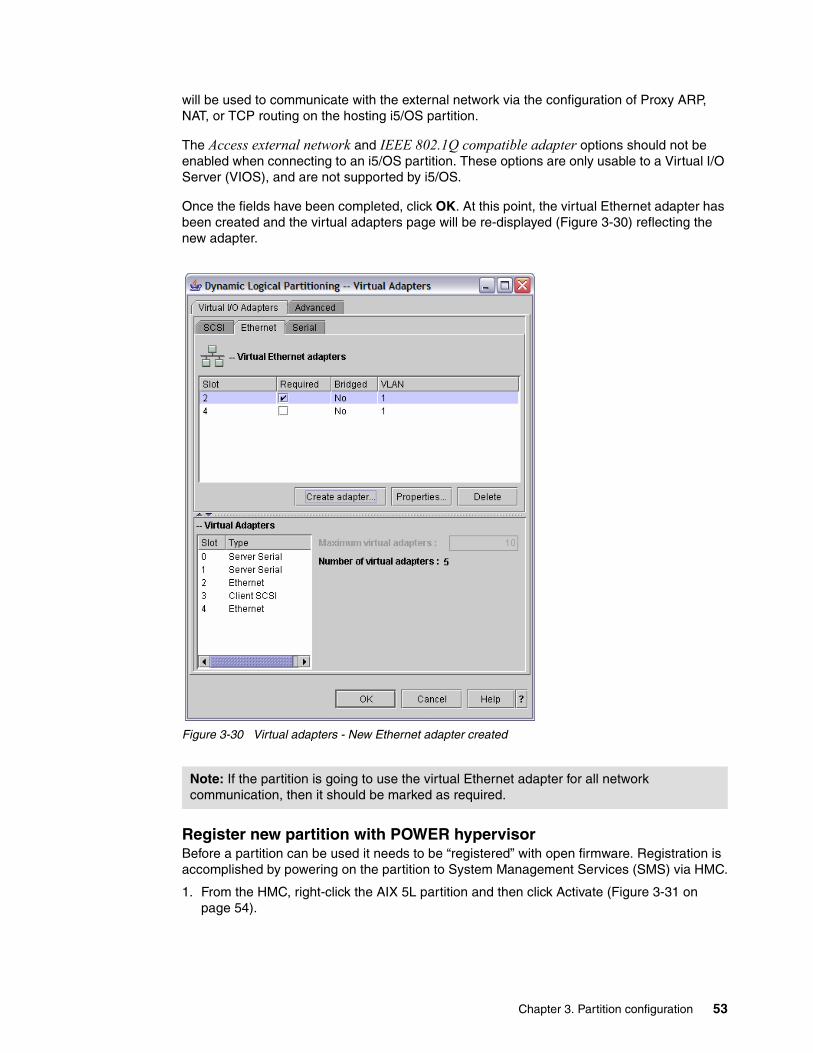
will be used to communicate with the external network via the configuration of Proxy ARP, NAT, or TCP routing on the hosting i5/OS partition.
The Access external network and IEEE 802.1Q compatible adapter options should not be enabled when connecting to an i5/OS partition. These options are only usable to a Virtual I/O Server (VIOS), and are not supported by i5/OS.
Once the fields have been completed, click OK. At this point, the virtual Ethernet adapter has been created and the virtual adapters page will be re-displayed (Figure 3-30) reflecting the new adapter.
Figure 3-30 Virtual adapters - New Ethernet adapter created
Register new partition with POWER hypervisorBefore a partition can be used it needs to be “registered” with open firmware. Registration is accomplished by powering on the partition to System Management Services (SMS) via HMC.
1. From the HMC, right-click the AIX 5L partition and then click Activate (Figure 3-31 on page 54).
Note: If the partition is going to use the virtual Ethernet adapter for all network communication, then it should be marked as required.
Chapter 3. Partition configuration 53

Figure 3-31 Partition activation
2. In Activate Logical Partition window, click Advanced as shown in Figure 3-32.
Figure 3-32 Partition activation - Advanced selection
3. Select SMS Boot mode and click OK, as shown in Figure 3-33 on page 55.
54 AIX 5L on the IBM System i Platform: Implementation Guide

Figure 3-33 Partition activation - Advanced, selection of SMS
4. Select Open a terminal window or console session in the Activate Logical Partition window and click OK, as shown in Figure 3-34.
Figure 3-34 Partition activation - Open terminal window
A message may be displayed in the virtual console window prompting for console selection (Figure 3-35 on page 56). If this message is displayed, press the 0 (zero) key.
Chapter 3. Partition configuration 55

Figure 3-35 Virtual terminal - Terminal selection message
At this point the resources defined in the partition profile will be reserved by hypervisor and the partition will be started. Since there is no I/O defined yet, the partition will eventually boot into the Firmware of the Partition (Figure 3-36 on page 57).
56 AIX 5L on the IBM System i Platform: Implementation Guide

Figure 3-36 Power PC Firmware menu
Now that the partition has been registered with hypervisor on the System i, the partition should be shut down. After closing the terminal window, on the HMC, right-click the AIX 5L partition and select Shut Down Partition.
A window will be displayed prompting for confirmation of the shutdown (Figure 3-37 on page 58). Since there is currently no operating system installed in the partition, click Immediate and then click OK.
Chapter 3. Partition configuration 57
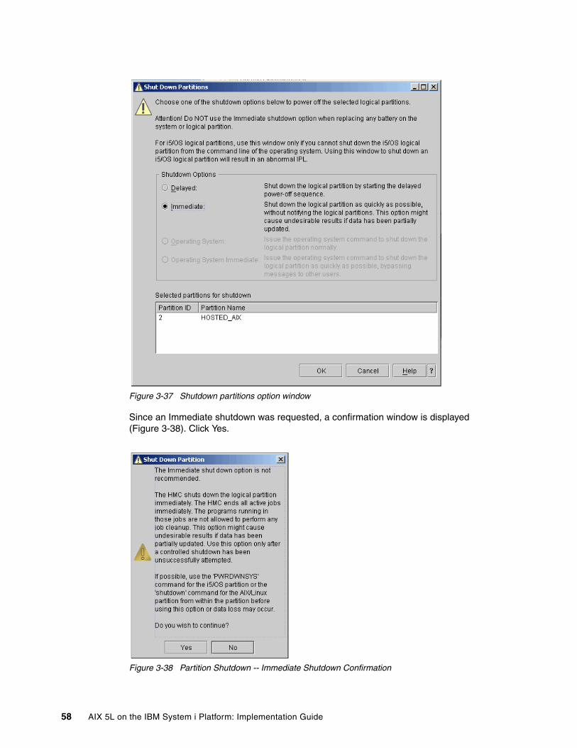
Figure 3-37 Shutdown partitions option window
Since an Immediate shutdown was requested, a confirmation window is displayed (Figure 3-38). Click Yes.
Figure 3-38 Partition Shutdown -- Immediate Shutdown Confirmation
58 AIX 5L on the IBM System i Platform: Implementation Guide

Depending on the version of HMC, an additional warning dialog may be displayed concerning replacement of a Cache battery (Figure 3-39). Click No to indicate that a cache battery is not being replaced. At this point the partition will be shutdown, and completely registered with hypervisor.
Figure 3-39 Cache battery replacement dialog
3.4.4 Virtual I/O definitions in i5/OS partition profileOnce the AIX 5L partition has been created, virtual adapters need to be created for the i5/OS partition to support virtual I/O, and optionally virtual console.
Virtual SCSI server adapter1. To create a virtual SCSI server adapter, bring up the partition profile properties, and select
the virtual I/O adapters tab as shown in Figure 3-40.
Figure 3-40 Partition profile properties - Virtual I/O selection
2. This will list the current virtual adapter configuration for this partition profile (Figure 3-41 on page 60).
Chapter 3. Partition configuration 59

Figure 3-41 Hosting i5/OS partition profile properties - Virtual I/O Adapters
3. To create the virtual SCSI Server adapter that will provide the virtual SCSI disk to the AIX 5L partition, ensure that the SCSI tab is selected and then select the Create server adapter button.
4. On the Virtual SCSI Server Adapter Properties window (Figure 3-42 on page 61). Complete the fields as follows:
a. Server slot: This is the slot number for the adapter being created. This slot number must match the slot number that the Virtual SCSI Client Adapter for the AIX 5L partition is pointing to.
b. Slot connection settings: Only selected client partition can connect
c. Client partition: The name of the AIX 5L partition selected from the pull-down list
d. Client partition slot: The slot number of the Virtual SCSI Client adapter for the AIX 5L partition.
60 AIX 5L on the IBM System i Platform: Implementation Guide

Figure 3-42 Hosting i5/OS partition profile properties - Create virtual SCSI server adapter
To help clarify, the Virtual SCSI Client adapter for the AIX 5L partition needs to point to the Virtual SCSI Server adapter for the hosting i5/OS partition and likewise, the virtual SCSI server adapter for the hosting i5/OS partition needs to point to the virtual SCSI client adapter for the AIX 5L partition.
As an example, we can look at Figure 3-43 which shows the properties of the virtual SCSI server adapter for the hosting i5/OS partition and mappings to the properties of the virtual SCSI client adapter for the AIX 5L partition.
Figure 3-43 Virtual SCSI adapters - Mapping example
Virtual SCSI server adapter properties on i5/OS partition
Virtual SCSI client adapter properties on AIX 5L partition
Client slot numbersNeed to match
Server slot numbersNeed to match
Chapter 3. Partition configuration 61

5. Once the fields of the Virtual SCSI - Server Adapter Properties have been completed, click OK. Then back on the Logical Partition Profile Properties window click OK.
At this point the virtual SCSI server adapter has been added to the profile of the hosting i5/OS partition. This means that the next time the i5/OS partition profile is activated from the HMC, the adapter will be available.
To add the adapter to the i5/OS partition without a restart of i5/OS will require that the adapter be added to the running state of the partition through the use of Dynamic LPAR, which will be covered in more detail in “DLPAR process for active partition” on page 67.
Virtual Ethernet adapter1. To create a virtual Ethernet adapter, bring up the partition profile properties, and select the
virtual I/O adapters tab as shown in Figure 3-44.
Figure 3-44 Partition profile properties - Virtual I/O selection
2. Click the Ethernet tab to display a list of the already configured virtual Ethernet adapters (Figure 3-45 on page 63).
Note: If this Virtual SCSI Server Adapter will be used to provide virtual SCSI disk, then it will need to be marked as Required to ensure its availability.
62 AIX 5L on the IBM System i Platform: Implementation Guide

Figure 3-45 Virtual Ethernet adapters
3. To create a new virtual Ethernet adapter, click Create adapter. This will show the dialog in Figure 3-46.
Figure 3-46 Virtual Ethernet Adapter - Properties page
Chapter 3. Partition configuration 63

This display has a significant amount of empty space, so lets focus on the necessary section, Figure 3-47, for adapter configuration.
Figure 3-47 Virtual Ethernet Adapter - Properties page close-up
4. The slot number refers to the position of the virtual Ethernet adapter on the virtual system bus. The virtual LAN ID is analogous to the current virtual LAN/Ethernet ID. For two partitions to be able to communicate, they will need to have a virtual Ethernet adapter configured for the same virtual LAN ID (VLAN).
Having the virtual Ethernet adapter occupy the same slot is not a requirement. The slot number can be left as provided. Enter the Virtual LAN number that corresponds to the virtual LAN that the AIX 5L partition is configured to use. If this is the only VLAN configured on this System i, then it can be left at the default.
5. Once the fields have been completed, click OK.
At this point, the virtual Ethernet adapter has been created (in the partition profile) and the partition profile page will be re-displayed (Figure 3-48 on page 65) reflecting the new adapter.
Note: If this virtual Ethernet adapter is going to be used to provide external network connectivity for an AIX 5L partition via a VLAN network, then it will need to be marked as Required.
64 AIX 5L on the IBM System i Platform: Implementation Guide

Figure 3-48 Partition profile properties - Virtual I/O Adapters
6. Click OK to complete the update of the partition profile.
Optional: Creating virtual client serial adapter on i5/OS partition
1. Optionally, we can configure virtual serial adapter to support virtual console access via the i5/OS partition. To accomplish this, click the Serial tab, and then click Create client adapter as shown in Figure 3-49 on page 66.
Note: After a virtual Ethernet adapter has been allocated to an i5/OS partition, an Ethernet line description, and TCP/IP interface, will need to be created. This process is explained in 5.2.2, “Creating the Ethernet Line Description in i5/OS” on page 100.
Note: This procedure is only necessary if you want a virtual console and plan to access the AIX 5L partition console via a telnet connection to port 2301(virtual console) on the i5/OS partition.
Chapter 3. Partition configuration 65

Figure 3-49 Virtual Serial Adapter properties
2. The Client slot setting can be left at default, which will be the next available slot number. The Server partition setting needs to be set to the name of the AIX 5L partition. In the example shown in Figure 3-50, this is set to HOSTED_AIX(2).
The Server partition slot will need to be set to 0. This will point to the server serial adapter in slot 0, for the AIX 5L partition. Once this information has been entered, click OK.
Figure 3-50 Virtual Serial Adapter Properties window
66 AIX 5L on the IBM System i Platform: Implementation Guide

3. If the AIX 5L partition will use only virtual resources, select the Required check box for Client Serial and then click OK.
DLPAR process for active partitionThe virtual I/O adapters will need to be created in the i5/OS partition profile, just as they were created in the AIX 5L partition profile.
However, it is important to note that partition profile modifications are enabled only when the partition profile is activated. This can present a problem if the host i5/OS partition is currently active and cannot be shutdown to allow for partition profile reactivation, updating hypervisor.
The easiest way to get additional virtual I/O adapters allocated to an active partition is through the Dynamic Logical Partitioning (DLPAR) process, as previously noted in 3.4.2, “DLPAR process” on page 46.
Chapter 3. Partition configuration 67

68 AIX 5L on the IBM System i Platform: Implementation Guide
Chapter 4. Storage configuration
This chapter covers the configuration of the storage environment for AIX 5L partitions on the System i platform. Information about virtual I/O and direct I/O is presented.
4
© Copyright IBM Corp. 2005. All rights reserved. 69

4.1 Virtual I/OUsing virtual I/O to provide storage to an AIX 5L partition, revolves around storage being hosted by an i5/OS partition, for an AIX 5L partition. You should have already created an AIX 5L partition profile with a virtual SCSI client adapter that points to a virtual SCSI server adapter for an i5/OS partition. This section will walk you through creating the i5/OS components to support virtual storage.
4.1.1 Network Server DescriptionA Network Server Description (NWSD) is used to give a name to the configuration, provide an interface for starting and stopping an AIX 5L partition, and provide a link between AIX 5L and its virtual disks.
Use the following steps to define the Network Server Description:
1. Start the Create Network Server Description using the CRTNWSD command (Figure 4-1).
Figure 4-1 Create network server description
– Network server description: This is the user-defined name for the network server description.
– Resource name: The resource name indicates the virtual SCSI server adapter that provides virtual I/O resources (virtual disk [NWSSTG], and/or virtual CD/DVD) to the AIX 5L partition that has the corresponding Virtual SCSI client adapter. *AUTO indicates that the system determines the resource name of the first virtual SCSI server adapter for the partition.
– Network server type → Server connection: This indicates the type of server that this network server is being created for. Since it is being created for an AIX 5L guest (hosted) partition, enter *GUEST.
Create Network Server Desc (CRTNWSD) Type choices, press Enter. Network server description . . . > AIX Name Resource name . . . . . . . . . > *AUTO Name, *NONE, *AUTO Network server type: Server connection . . . . . . > *GUEST *IXSVR, *ISCSI, *GUEST... Server operating system . . . > *AIXPPC *WIN32, *LINUX32... Online at IPL . . . . . . . . . *YES *YES, *NO Vary on wait . . . . . . . . . . *NOWAIT *NOWAIT, 1-15 minutes Shutdown timeout . . . . . . . . 15 2-45 minutes Partition . . . . . . . . . . . *NONE Partition number . . . . . . . . 2 Number, *NONE Code page . . . . . . . . . . . *LNGVER *LNGVER, 437, 850, 852, 857... Server message queue . . . . . . *JOBLOG Name, *JOBLOG, *NONE Library . . . . . . . . . . . Name, *LIBL, *CURLIB More... F3=Exit F4=Prompt F5=Refresh F12=Cancel F13=How to use this display F24=More keys
70 AIX 5L on the IBM System i Platform: Implementation Guide

– Network server type → Server operating system: This indicates the operating system type. For AIX 5L partitions, set it to *AIXPPC.
– Online at IPL: This field is typically left set at the default of *YES. It indicates whether or not this network server should be varied on when i5/OS is started. By leaving the value at *YES, the NWSD will be started when the i5/OS partition is started.
– Vary on wait: This field is typically left set at the default value of *NOWAIT. It indicates the amount of time to wait after start of i5/OS before vary on of this network server. It is typically used when the start of the guest operating system (in this case AIX 5L) needs to wait for another operating system/server to start (such as when a Linux file server is integrated with an Windows Active Directory® Server running on a IXS/IXA).
– Shutdown timeout: This field is typically left set at the default value of 15. It indicates how long i5/OS will wait on a vary off before forcing the network server into a vary off state. Typically, when a network server is varied off it will send a signal to the guest operating system, indicating that it should shut-down. Once the guest operating system is shutdown, the network server will go into a vary off state. This value only comes into play when the shutdown of the guest operating system fails.
– Partition: Name of the AIX 5L partition. This name must match the name of the partition as configured on the HMC, and is case sensitive. It may be left at the default of *NONE, if either the next field Partition number is configured, or the Resource Name is defined.
– Partition number: Unique number identifier for the partition as defined on the HMC. This field cannot be specified if the Partition name field has been specified.
– Code page: Since this parameter is not used when Server connection is set to *GUEST, it must be left at the default value of *LNGVER.
2. After you complete the first page of parameters, press the <PgDn> key to display the next screen (Figure 4-2 on page 72).
Note: Prior to V5R4, the network server type was a single field and was set to *GUEST for AIX 5L partitions.
Note: When Server connection specified is *GUEST for the network server type (TYPE) parameter, either the Partition (PARTITION) or Partition number (PTNNBR) parameter may be specified, but both parameters cannot be specified.
When Server connection specified is *GUEST for the Network server type (TYPE) parameter and a Resource name (RSRCNAME) is specified, the Partition (PARTITION) and Partition number (PTNNBR) parameter can be set to *NONE.
Chapter 4. Storage configuration 71
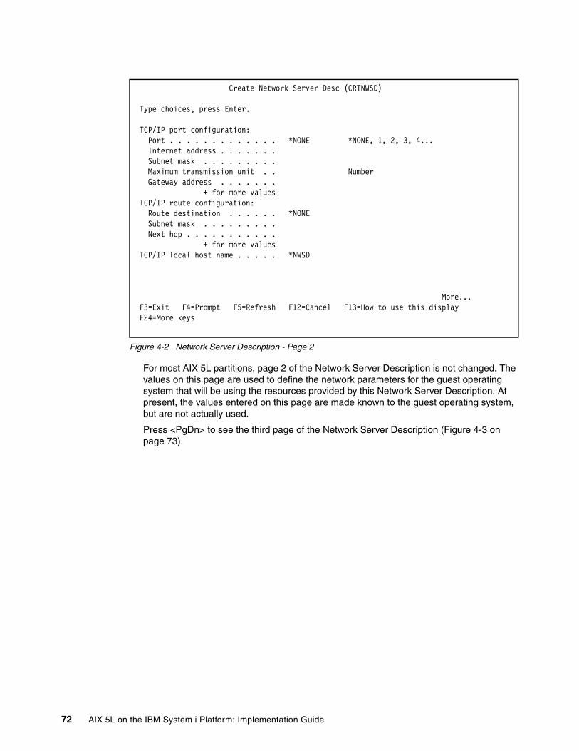
Figure 4-2 Network Server Description - Page 2
For most AIX 5L partitions, page 2 of the Network Server Description is not changed. The values on this page are used to define the network parameters for the guest operating system that will be using the resources provided by this Network Server Description. At present, the values entered on this page are made known to the guest operating system, but are not actually used.
Press <PgDn> to see the third page of the Network Server Description (Figure 4-3 on page 73).
Create Network Server Desc (CRTNWSD) Type choices, press Enter. TCP/IP port configuration: Port . . . . . . . . . . . . . *NONE *NONE, 1, 2, 3, 4... Internet address . . . . . . . Subnet mask . . . . . . . . . Maximum transmission unit . . Number Gateway address . . . . . . . + for more values TCP/IP route configuration: Route destination . . . . . . *NONE Subnet mask . . . . . . . . . Next hop . . . . . . . . . . . + for more values TCP/IP local host name . . . . . *NWSD More... F3=Exit F4=Prompt F5=Refresh F12=Cancel F13=How to use this display F24=More keys
72 AIX 5L on the IBM System i Platform: Implementation Guide

Figure 4-3 Network Server Description - Page 3
– TCP/IP local domain name: Leave as default value of *SYS.
– TCP/IP name server system: Leave as default value of *SYS
– Restricted device resources: Typically this value is left at the default of *NONE. This field is used to indicate if any I/O owned by the i5/OS partition should not be made available to the AIX 5L partition. By default, when a Network Server description is created for an AIX 5L partition, the CD/DVD and Tape devices owned by the hosting i5/OS partition, are made available as Virtual I/O devices to the hosted AIX 5L partition. In addition to specifying the name(s) of specific devices to restrict from the AIX 5L partition, other possible values for this field include:
• *ALL: Restrict all I/O devices from the AIX 5L partition with the exception of those Network server Storage spaces that are explicitly linked to the Network Server Description.
• *ALLTAPE: Restrict all tape devices from the AIX 5L partition.
• *ALLOPT: Restrict all optical (that is, CD/DVD/DVD-RAM) devices from the AIX 5L partition.
– Synchronize date and time: Leave at the default value of *TYPE.
– IPL source: Indicates where to look for the initial boot file. Possible settings for this field include:
• *NWSSTG: indicates that the initial boot file is in the bootable disk partition (PrepBoot) of the first disk linked to the Network Server Description.
• *STMF: Indicates that the initial boot file is a stream file located in the Integrated FIle System (IFS). When the setting is *STMF, the path will be specified in the IPL stream file field.
• *PANEL: Indicates that the setting in the HMC for the partition should be used.
Create Network Server Desc (CRTNWSD) Type choices, press Enter. TCP/IP local domain name . . . . *SYS TCP/IP name server system . . . *SYS + for more values Restricted device resources . . *NONE Name, *NONE, *ALL... + for more values Synchronize date and time . . . *TYPE *TYPE, *YES, *NO IPL source . . . . . . . . . . . *NWSSTG *NWSSTG, *PANEL, *STMF, A... IPL stream file . . . . . . . . *NONE IPL parameters . . . . . . . . . *NONE Power control . . . . . . . . . *YES *YES, *NO Authority . . . . . . . . . . . *CHANGE Name, *CHANGE, *ALL, *USE... More... F3=Exit F4=Prompt F5=Refresh F12=Cancel F13=How to use this display F24=More keys
Chapter 4. Storage configuration 73

• A, B, D: Not applicable for Network Server descriptions associated with AIX 5L partitions.
– IPL stream file: The IPL stream file is specified when the IPL source is set to *STMF. The path indicates the path to the initial boot file located in the IFS.
– IPL parameters: Specifies a string of characters that will be passed to the load image at IPL time. It consists of commands or configuration information for the guest operating system.
– Power control: Indicates if this is a power controlling Network Server Description. A power controlling Network Server Description is one that sends power requests to hypervisor when a vary operation (such as vary on / vary off) is performed on the Network Server Description. Put another way, when a power controlling Network Server Description is varied on, the associated Logical partition will be activated, and when the power controlling Network Server Description is varied off, the associated Logical partition will be shut down.
This setting can be used to activate/deactivate the associated partition. Setting this parameter to *YES indicates the associated partition will be activated/deactivated by varying on/off the NWSD.
If the partition activate/deactivate will be managed from HMC, then this parameter should be set to *NO. However if the NWSD is providing access to virtual disk that is being used for rootvg, then it will be necessary to make sure the NWSD is varied on before the partition profile is activated.
For most AIX 5L implementations on the System i platform that utilize virtual disk, this setting can be left at the default of *YES. A setting of *NO will be used when there are multiple Network Server Descriptions defined for the same Logical partition, and/or the hosting i5/OS partition will not be used for activating or deactivating the AIX 5L partition.
– Authority: Leave set as the default value of *CHANGE
Press <PgDn> to see the fourth (and last) page of the Network Server Description (Figure 4-4 on page 75).
Note: When using virtual CD/DVD to install AIX 5L and Power control is set to *YES, then IPL source will need to be set to *PANEL, and the AIX 5L partition profile will need to have Boot Mode set to SMS or OPEN_FIRMWARE. These settings will only be necessary for initial install, and this process will be covered in more detail in 6.1, “New virtual CD-ROM installation process” on page 122.
Note: The parameters defined in IPL parameters are sent directly to the AIX 5L operating system; therefore, you must observe case sensitivity.
Note: For the power-control requests sent by the vary operation to be accepted by hypervisor, the Power Controlling Partition setting in the AIX 5L partition profile must be set to the name of the i5/OS partition that will issue the power request.
74 AIX 5L on the IBM System i Platform: Implementation Guide

Figure 4-4 Network Server Description - Page 4
– Text ‘description’: Enter a description of the usage of the Network Server Description, if desired.
3. After you complete the fields, press Enter to create the Network Server Description.
4.1.2 Network Server Storage SpaceThe Network Server Storage Space (NWSSTG), also referred to as virtual disk, provides the disk resource for the AIX 5L partition. Network Server Storage spaces are i5/OS objects that are used as disk drives for hosted servers. A storage space can be compared to a Volume or Logical disk.
Use the following steps to create a Network Server Storage Space:
1. Type the Create Network Server Storage Space command CRTNWSSTG, and press <F4> to prompt the command (Figure 4-5).
Figure 4-5 Create Network Server Storage Space
– Network server storage space: The Network server storage space is a user-defined name given to the network server storage space.
– Size: The size field indicates the size (in megabytes) of the storage space, which will be used as a virtual disk. The size can be anywhere from 1 megabyte to 1 terabyte, and will need to be defined. If it is left at *CALC, it will create a 1 megabyte storage space. For an AIX 5L installation, the installer will need to determine the optimum size of the virtual disk, but it must be a minimum of 2.2 gigabyte.
– From storage space: This field is used when making a copy of an existing storage space. If this storage space is being created for a new installation, or to add an additional virtual drive to an existing server, leave the value set at the default of *NONE.
Create Network Server Desc (CRTNWSD) Type choices, press Enter. Text 'description' . . . . . . . *BLANK
Bottom F3=Exit F4=Prompt F5=Refresh F12=Cancel F13=How to use this display F24=More keys
Create NWS Storage Space (CRTNWSSTG) Type choices, press Enter. Network server storage space . . AIX Drive Name Size . . . . . . . . . . . . . . 8192 *CALC, 1-1024000 megabytes From storage space . . . . . . . *NONE Name, *NONE Format . . . . . . . . . . . . . *OPEN *NTFS, *FAT, *FAT32, *OPEN... Auxiliary storage pool ID . . . 1 1-255 ASP device . . . . . . . . . . . Name
Chapter 4. Storage configuration 75
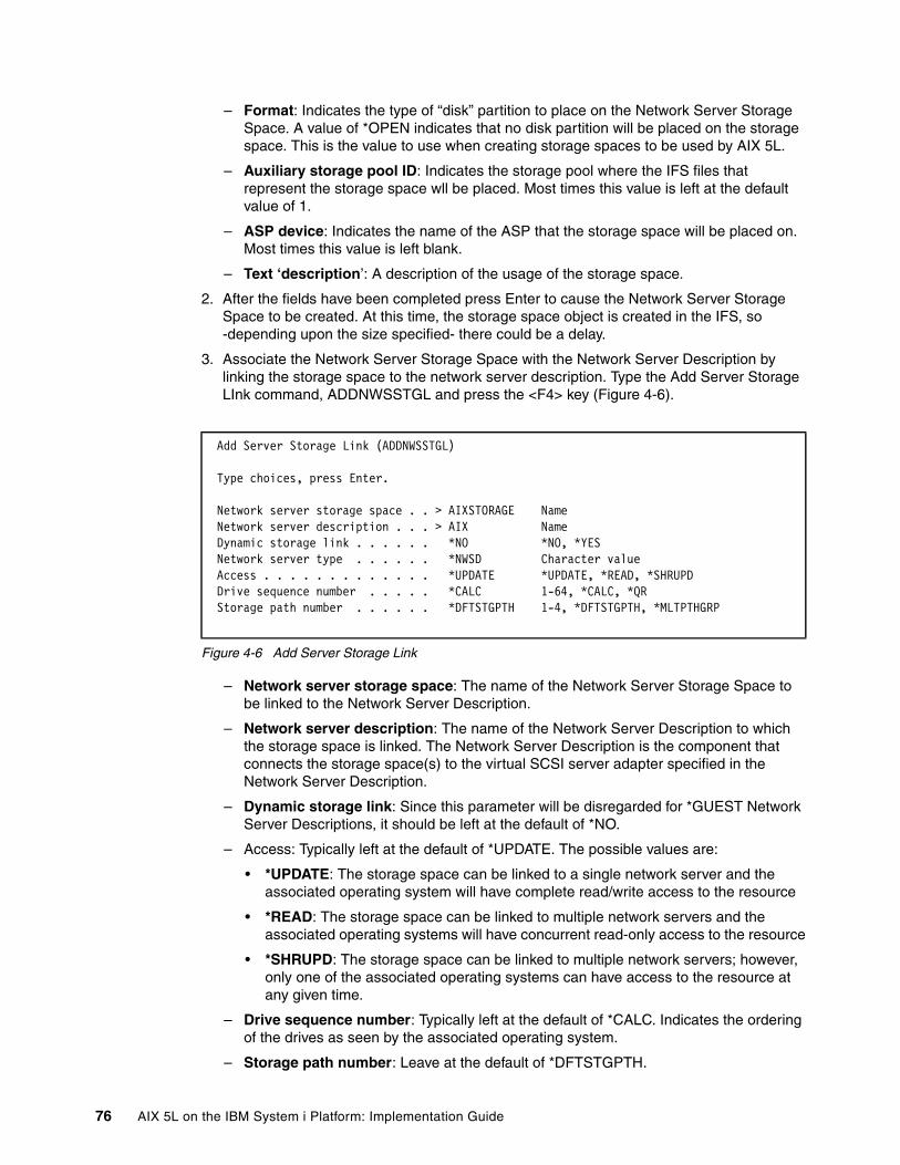
– Format: Indicates the type of “disk” partition to place on the Network Server Storage Space. A value of *OPEN indicates that no disk partition will be placed on the storage space. This is the value to use when creating storage spaces to be used by AIX 5L.
– Auxiliary storage pool ID: Indicates the storage pool where the IFS files that represent the storage space wll be placed. Most times this value is left at the default value of 1.
– ASP device: Indicates the name of the ASP that the storage space will be placed on. Most times this value is left blank.
– Text ‘description’: A description of the usage of the storage space.
2. After the fields have been completed press Enter to cause the Network Server Storage Space to be created. At this time, the storage space object is created in the IFS, so -depending upon the size specified- there could be a delay.
3. Associate the Network Server Storage Space with the Network Server Description by linking the storage space to the network server description. Type the Add Server Storage LInk command, ADDNWSSTGL and press the <F4> key (Figure 4-6).
Figure 4-6 Add Server Storage Link
– Network server storage space: The name of the Network Server Storage Space to be linked to the Network Server Description.
– Network server description: The name of the Network Server Description to which the storage space is linked. The Network Server Description is the component that connects the storage space(s) to the virtual SCSI server adapter specified in the Network Server Description.
– Dynamic storage link: Since this parameter will be disregarded for *GUEST Network Server Descriptions, it should be left at the default of *NO.
– Access: Typically left at the default of *UPDATE. The possible values are:
• *UPDATE: The storage space can be linked to a single network server and the associated operating system will have complete read/write access to the resource
• *READ: The storage space can be linked to multiple network servers and the associated operating systems will have concurrent read-only access to the resource
• *SHRUPD: The storage space can be linked to multiple network servers; however, only one of the associated operating systems can have access to the resource at any given time.
– Drive sequence number: Typically left at the default of *CALC. Indicates the ordering of the drives as seen by the associated operating system.
– Storage path number: Leave at the default of *DFTSTGPTH.
Add Server Storage Link (ADDNWSSTGL) Type choices, press Enter. Network server storage space . . > AIXSTORAGE Name Network server description . . . > AIX Name Dynamic storage link . . . . . . *NO *NO, *YES Network server type . . . . . . *NWSD Character value Access . . . . . . . . . . . . . *UPDATE *UPDATE, *READ, *SHRUPD Drive sequence number . . . . . *CALC 1-64, *CALC, *QR Storage path number . . . . . . *DFTSTGPTH 1-4, *DFTSTGPTH, *MLTPTHGRP
76 AIX 5L on the IBM System i Platform: Implementation Guide

After this has been completed, the i5/OS objects will be configured correctly to provide support for virtual SCSI disk drives.
4.1.3 Performance considerationsTo avoid potential performance issues with i5/OS V5R3M0, it is important to determine the optimum size of NWSSTG, and if it will necessary to use multiple NWSSTGs along with multiple NWSDs. Due to the way virtual SCSI operations were processed by i5/OS V5R3M0, there is a possibility of a performance bottleneck occurring.
This bottleneck is due to the fact that i5/OS V5R3M0 limits virtual SCSI server adapters to one operation at a time. Therefore only one SCSI operation can be outstanding before an additional SCSI operation was started.
In certain scenarios, this bottleneck can be cause less than expected response time when using a single NWSD to access virtual disk. The use of a single NWSD will cause all virtual SCSI operations to flow through a single virtual SCSI server adapter. Since the bottleneck will be at the NWSD level, this will occur even when using multiple NWSSTGs linked to the same NWSD, as shown in Figure 4-7.
Figure 4-7 i5/OS V5R3M0 virtual SCSI bottleneck diagram
To maximize performance with i5/OS V5R3M0, create multiple Virtual SCSI client/server adapters, paired between the AIX 5L partition and the i5/OS partition. Each virtual SCSI pipeline corresponds to a NWSD on the host i5/OS partition, with up to 64 NWSSTGs attached to each NWSD. This setup has multiple I/O paths, as shown in Figure 4-8 on page 78.
File Systems
NWSSTGs
8 GB
8 GB
FS
LV
VG
35 GB
35 GB
FS
LV
VG
24 GB
NWSD
24 GB
FS
LV
VG
15 GB
15 GB
FS
LV
VG
Logical Volumes
Volume Groups
AIX 5L
i5/OS V5R3M0Possiblebottleneck
Chapter 4. Storage configuration 77

Figure 4-8 i5/OS V5R3M0 multiple NWSD connection diagram
This configuration scenario enables an AIX 5L partition to perform multiple, simultaneous I/O operations through multiple VSCSI connections.
Fortunately the virtual SCSI limitation was removed from i5/OS V5R3M5 and i5/OS V5R4M0, and some additional enhancements were added to the virtual storage architecture. These enhancements allow an AIX 5L partition to send multiple I/O requests to multiple NWSSTGs in an i5/OS partition through a single Virtual I/O path as shown in Figure 4-9 on page 79.
Parallelism with I/Orequests to separateVGs and hdisks
File Systems
NWSSTGs
VSCSIServerAdapter
8 GB
NWSD
VSCSIClientAdapter
hdisk0
8 GB
rootvg
FS
LV
VG
VSCSIServerAdapter
1.02 TB
NWSD
VSCSIClientAdapter
hdisk1
1.02 TB
app1
FS
LV
VG
VSCSIServerAdapter
512 GB
NWSD
VSCSIClientAdapter
hdisk2
512 GB
app2
FS
LV
VG
VSCSIServerAdapter
100 GB
NWSD
VSCSIClientAdapter
hdisk3
100 GB
temp
FS
LV
VG
Logical Volumes
Volume Groups
AIX 5L
i5/OS
78 AIX 5L on the IBM System i Platform: Implementation Guide
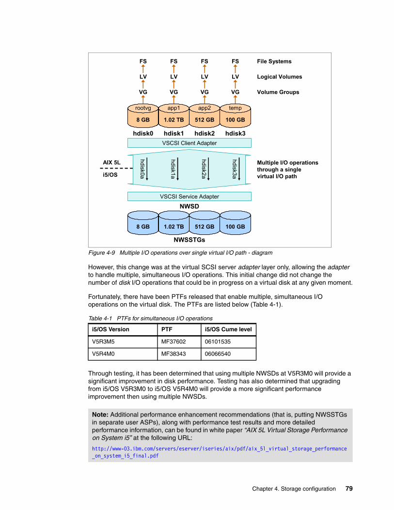
Figure 4-9 Multiple I/O operations over single virtual I/O path - diagram
However, this change was at the virtual SCSI server adapter layer only, allowing the adapter to handle multiple, simultaneous I/O operations. This initial change did not change the number of disk I/O operations that could be in progress on a virtual disk at any given moment.
Fortunately, there have been PTFs released that enable multiple, simultaneous I/O operations on the virtual disk. The PTFs are listed below (Table 4-1).
Table 4-1 PTFs for simultaneous I/O operations
Through testing, it has been determined that using multiple NWSDs at V5R3M0 will provide a significant improvement in disk performance. Testing has also determined that upgrading from i5/OS V5R3M0 to i5/OS V5R4M0 will provide a more significant performance improvement then using multiple NWSDs.
i5/OS Version PTF i5/OS Cume level
V5R3M5 MF37602 06101535
V5R4M0 MF38343 06066540
Note: Additional performance enhancement recommendations (that is, putting NWSSTGs in separate user ASPs), along with performance test results and more detailed performance information, can be found in white paper “AIX 5L Virtual Storage Performance on System i5” at the following URL:
http://www-03.ibm.com/servers/eserver/iseries/aix/pdf/aix_5l_virtual_storage_performance_on_system_i5_final.pdf
hdisk3a
hdisk2a
hdisk1a
hdisk0a
VSCSI Client Adapter
Multiple I/O operationsthrough a singlevirtual I/O path
File Systems
NWSSTGs
8 GB
hdisk0
8 GB
rootvg
FS
LV
VG
1.02 TB
NWSD
hdisk1
1.02 TB
app1
FS
LV
VG
512 GB
hdisk2
512 GB
app2
FS
LV
VG
100 GB
hdisk3
100 GB
temp
FS
LV
VG
Logical Volumes
Volume Groups
AIX 5L
i5/OS
VSCSI Service Adapter
Chapter 4. Storage configuration 79

4.2 Direct I/OWhen allocating a SCSI controller I/O adapter (IOA) to an AIX 5L partition, and it is downstream of a System i I/O Processor (IOP) adapter, and the IOP is allocated to an i5/OS partition, the IOA will need to be de-allocated from the i5/OS partition before it can be allocated to an AIX 5L partition.
To determine if a IOA is downstream from an IOP, open the managed system properties, and go to the I/O tab. Once there, expand the busses to reveal the physical adapters on each bus. The example shown in Figure 4-10, shows a PCI Ultra4 SCSI Disk Controller IOA in Slot C02, which is downstream of a PCI I/O Processor adapter in slot C01. Since The SCSI Controller IOA in slot C02 is showing that it is owned by partition RCHAS60_i5/OS, it will need to be de-allocated from the i5/OS partition before it can be allocated to an AIX 5L partition.
Figure 4-10 Managed system - I/O properties, SCSI disk controller - IOP
If the IOA in question has been marked as Required, then it will need to be removed from the i5/OS partition’s profile, and the i5/OS partition’s profile will need to be reactivated to make the IOA available for allocation to a different partition.
4.2.1 Configuration of Direct I/O disk unitsWhen implementing AIX 5L in a logical partition (LPAR) on System i, there are several storage choices: internal SCSI, virtual SCSI, or Fibre Channel-attached storage. Internal SCSI storage provides two further options:
80 AIX 5L on the IBM System i Platform: Implementation Guide

� IBM eServer iSeries disk units supported for AIX 5L on System i, with feature codes 4319, 4326, 4327 and 4328. This is a complete list at the time of publishing.
� IBM eServer pSeries disk units supported for AIX 5L on System i, with feature codes 1893, 1894, 1895, 1896, 1897 and 1898. This is a complete list at the time of publishing.
For all currently supported I/O hardware for AIX 5L on System i, see “AIX 5L Facts and Features” at:
http://www-03.ibm.com/servers/eserver/iseries/aix/getting_started.html
Both of these options are valid and supported by the System Planning Tool (SPT), the LPAR Validation Tool (LVT) and the IBM eConfigurator. If pSeries disk units are ordered for AIX 5L on System i, they will be configured the same as disk units on IBM System p systems.
For more information about configuration and usage of pSeries disk units for AIX 5L, consult PCIX SCSI RAID Controller Reference Guide for AIX, SA23-1323, which can be found in hardware section of the System p and AIX 5L Information Center:
http://publib.boulder.ibm.com/infocenter/pseries/v5r3/index.jsp
(Click System p Hardware → Select by installable option → SCSI PCI Adapters)
iSeries and pSeries disk units both perform well; however, iSeries disk units allow for greater flexibility because they are supported for both AIX 5L and i5/OS. However, pSeries disk units do not support i5/OS.
Using iSeries disk units for AIX 5L on System i provides the flexibility to move drives between i5/OS and AIX 5L partitions, maximizing the return on investment (ROI) of the solution.
The table below (Figure 4-11 on page 82) provides a summary of iSeries and pSeries SCSI disk units supported for AIX 5L on System i.
Note: The capability to move iSeries SCSI disk units between i5/OS and AIX 5L does not imply a dynamic move between running logical partitions. If the drives are in use by ai5/OS partition, they must be excluded from that partition before they can be allocated to an AIX 5L partition.
Chapter 4. Storage configuration 81

Figure 4-11 Disk unit chart
4.2.2 Configuring iSeries disk units for AIX 5L RAIDiSeries disk units in a RAID-5 or RAID-10 (mirroring at the adapter level) array provide an AIX 5L partition with the reliability of parity protection and the flexibility to reuse the drives for i5/OS at a later time. In addition, drives that are formatted to 522 bytes and included in a RAID array allow the IBM RAID adapter to utilize its advanced functions, taking full advantage of its read (if present) and write caches. This benefit becomes much greater if the adapter is a FC #2780 SCSI adapter (FC #0627 for AIX 5L), which has large read and write caches.
While it is possible to reformat iSeries drives to 512 bytes per sector, making them usable to AIX 5L in a pass-through fashion, this is not a recommended solution and is strongly discouraged. Using the disk units in this fashion will not leverage the RAID adapter’s advanced functions, specifically the read and write caches.
If the drives are in use by an operating system, they must be excluded from the operating system’s configuration.
For example; All of the disk units in a System i have been allocated to an i5/OS partition, and have been put in a Auxiliary Storage Pool (ASP). To allocate any of the disk units to an AIX 5L partition, they must be safely removed from the ASP to which they belong.
Depending on the server configuration, some or all of the steps below may be necessary before the process of including iSeries disk units in an AIX 5L RAID array can begin.
1. Stop allocation of data to the drives and migrate existing data off them.
2. Remove the drives from their ASP (this must be done from DST on the i5/OS partition).
YesYesSupported for AIX 5L mirroring?
YesYesSupported for AIX 5L RAID?
NoYesSupport for i5/OS?
512 bytes per sector, optimized for AIX 5L
iSeries 522 bytes per sector
Format from manufacturing
1893, 1894, 1895, 1896, 1897, 1898
4319, 4326, 4327, 4328
Feature codes supported for AIX 5L on System i
pSeries Disk unitsiSeries Disk units
Note: There are additional disk configuration checklists available at the iSeries Information Center, V5R4, under Systems management → Disk management → Configure your disks → Choose the correct procedure for configuring disks
http://publib.boulder.ibm.com/infocenter/iseries/v5r4/index.jsp
82 AIX 5L on the IBM System i Platform: Implementation Guide

3. If possible, dynamically remove the SCSI adapter managing the drives from the i5/OS partition, then dynamically add it to the AIX 5L partition.
It is not necessary to physically move the drives or adapter, unless the adapter is downstream from an IOP adapter.
4. De-allocate the SCSI controller managing the drives in the i5/OS partition profile to make the configuration change permanent.
4.2.3 SCSI disk units under AIX 5LWhen disk units are discovered under AIX 5L, they are assigned a device name using either the hdisk form, or the pdisk form.
pSeries disk units are formatted to 512 bytes per sector by default, and receive a hdisk name.
� For RAID, pSeries disk units must be reformatted to “pSeries” 522 bytes per sector. pSeries disk units reformatted to 522 bytes per sector carry a pdisk name, and are recognized as “array candidates.” When a RAID array is created from multiple pdisks, it is assigned an hdisk name. AIX 5L will then access only this single hdisk through the SCSI adapter, not the underlying pdisks.
� For OS-level mirroring, pSeries disk units are immediately usable as shipped from IBM. Mirroring is accomplished within the AIX 5L partition by using the Logical Volume Manager (LVM).
iSeries disk units are formatted to “iSeries” 522 bytes per sector by default, and receive a pdisk name. If the drives have never been used before, they will be recognized as “array candidates” in an active state. If the drives have been used by i5/OS, their state will be “RWProtected.”
� For RAID, iSeries disk units should be reformatted to “pSeries” 522 bytes per sector. As with pSeries disk units, once a RAID array is created, it will be assigned a single hdisk name.
� For OS-level mirroring, each iSeries disk unit should be marked as a separate striping (RAID-0) array, and not reformatted to 512 bytes per sector. As with pSeries disk units, mirroring is accomplished within the AIX 5L partition by using the Logical Volume Manager (LVM).
Recommended solutionWhen using internal SCSI disk units with AIX 5L on System i, the recommended solution is to use iSeries disk units in a RAID array. This approach provides the flexibility of being able to reuse the disk units for i5/OS at a later time and the reliability of parity protection. The supported RAID types are RAID-5 and RAID-10 (which is mirroring at the hardware, or adapter, level).
OS-level mirroring is also supported for AIX 5L on System i. If the AIX 5L partition is using a non-RAID adapter, OS- level mirroring becomes the only disk protection option.
Note: If the SCSI adapter has been marked as Required, it cannot be dynamically removed from an active partition. The only way to remove the SCSI adapter in this situation is to remove it from the partition profile, and reactivate the partition profile.
Chapter 4. Storage configuration 83

4.2.4 SCSI disk unit preparationAfter the SCSI adapter, and attached disk units, have been successfully allocated to the AIX 5L partition, the disk units will need to be prepared for use by AIX 5L.
Using the Standalone Diagnostics CD-ROMThe Standalone Diagnostics CD-ROM allows SCSI RAID array management to be performed prior to installing AIX 5L. It is available for download at no cost at:
http://www14.software.ibm.com/webapp/set2/sas/f/diags/download/home.html
Choose the CDlatest.iso file.
To use the RAID Array Manager prior to installing AIX 5L, boot the AIX 5L partition from the CD-ROM, and on the partition console, enter “vt340” as the desired terminal type when prompted.
Displaying the Initial Drive ConfigurationAt the main Standalone Diagnostics menu (“Function Selection”), follow these steps to access the RAID Array Manager: Task Selection (Diagnostics, Advanced Diagnostics, Service Aids, and so on) → RAID Array Manager → PCI-X SCSI Disk Array Manager.
The Disk Array Manager menu is the starting point for all RAID configuration procedures, as shown in Figure 4-12.
Figure 4-12 SCSI Disk Array Manager screen
To display all internal SCSI disk units controlled by adapters allocated to this AIX 5L partition, select List PCI-X SCSI Disk Array Configuration, then select each SCSI adapter in turn and press F7. Press enter to display the configuration.
Note: if AIX 5L is already installed and running, the RAID Array Manager can be accessed through the System Management Interface Tool (SMIT). After logging in as “root,” enter smit devices → Disk Array → IBM PCI-X SCSI Disk Array → PCI-X SCSI Disk Array Manager.
84 AIX 5L on the IBM System i Platform: Implementation Guide

The example shown in Figure 4-13 shows two RAID adapters, the second of which controls at least five iSeries disk units. They are assigned pdisk names, and are identified as array candidates in an active state.
Figure 4-13 SCSI Disk Array status
As noted previously, new iSeries disk units are recognized as “array candidates” in an active state. If the disk units have been used by i5/OS, they would be read/write protected, and their state would be RWProtected as shown in Figure 4-14.
Figure 4-14 iSeries Disk units in RWProtected state
Reformatting the iSeries disk unitsIf the state of the iSeries disk units is “RWProtected,” they must be reformatted to “pSeries” 522 bytes per sector, before they can be included in a RAID array. If the iSeries disk units have never been used before, such a reformat is not mandatory, but is still recommended. This will make the disk unit “known zeroed” to the adapter. This will allow all disk units to be protected as soon as an RAID array is created, eliminating the need for a rebuild of the array. It also greatly speeds up the creation of the array.
To format a iSeries disk unit to pSeries 522 bytes per sector, use the following steps from the main RAID Array Manager menu: Create an Array Candidate pdisk and Format to 522 Byte Sectors → select the correct SCSI adapter, press F7, and then press Enter → select each
Chapter 4. Storage configuration 85
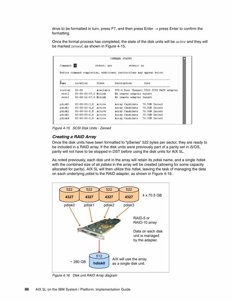
drive to be formatted in turn, press F7, and then press Enter → press Enter to confirm the formatting.
Once the format process has completed, the state of the disk units will be active and they will be marked zeroed, as shown in Figure 4-15.
Figure 4-15 SCSI Disk Units - Zeroed
Creating a RAID ArrayOnce the disk units have been formatted to “pSeries” 522 bytes per sector, they are ready to be included in a RAID array. If the disk units were previously part of a parity set in i5/OS, parity will not have to be stopped in DST before using the disk units for AIX 5L.
As noted previously, each disk unit in the array will retain its pdisk name, and a single hdisk with the combined size of all pdisks in the array will be created (allowing for some capacity allocated for parity). AIX 5L will then utilize this hdisk, leaving the task of managing the data on each underlying pdisk to the RAID adapter, as shown in Figure 4-16.
Figure 4-16 Disk unit RAID Array diagram
4327 4327 4327 4327
RAID-5 or RAID-10 array
Data on each diskunit is managed by the adapter.
4 x 70.5 GB522522 522 522
pdisk0 pdisk1 pdisk2 pdisk3
AIX will use the arrayas a single disk unit.hdisk0
512~ 280 GB
86 AIX 5L on the IBM System i Platform: Implementation Guide
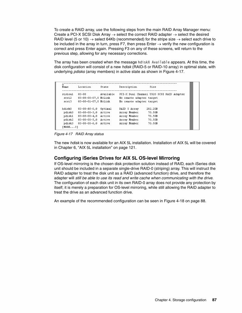
To create a RAID array, use the following steps from the main RAID Array Manager menu: Create a PCI-X SCSI Disk Array → select the correct RAID adapter → select the desired RAID level (5 or 10) → select 64Kb (recommended) for the stripe size → select each drive to be included in the array in turn, press F7, then press Enter → verify the new configuration is correct and press Enter again. Pressing F3 on any of these screens, will return to the previous step, allowing for any necessary corrections.
The array has been created when the message hdiskX Available appears. At this time, the disk configuration will consist of a new hdisk (RAID-5 or RAID-10 array) in optimal state, with underlying pdisks (array members) in active state as shown in Figure 4-17.
Figure 4-17 RAID Array status
The new hdisk is now available for an AIX 5L installation. Installation of AIX 5L will be covered in Chapter 6, “AIX 5L installation” on page 121.
Configuring iSeries Drives for AIX 5L OS-level MirroringIf OS-level mirroring is the chosen disk protection solution instead of RAID, each iSeries disk unit should be included in a separate single-drive RAID-0 (striping) array. This will instruct the RAID adapter to treat the disk unit as a RAID (advanced function) drive, and therefore the adapter will still be able to use its read and write cache when communicating with the drive. The configuration of each disk unit in its own RAID-0 array does not provide any protection by itself; it is merely a preparation for OS-level mirroring, while still allowing the RAID adapter to treat the drive as an advanced function drive.
An example of the recommended configuration can be seen in Figure 4-18 on page 88.
Chapter 4. Storage configuration 87

Figure 4-18 Disk unit mirroring diagram
The process of creating a RAID-0 array from each iSeries disk unit is very similar to that of creating a RAID-5 array from multiple disk units, as described earlier. The only differences are the RAID level (0) and the number of disk units selected for inclusion in the RAID-0 array (only one). Repeat the process for each iSeries disk unit that will be used for mirroring. When the configuration is complete, each iSeries disk unit will be recognized as a new hdisk (RAID-0 array), with an underlying pdisk (array member), as shown in Figure 4-19.
Figure 4-19 SCSI Disk unit RAID-0 build screen
Each iSeries disk unit is now ready to be included in a mirroring solution. As noted previously, OS-level mirroring is performed within the AIX 5L operating system, with the help of the Logical Volume Manager (LVM). Once AIX 5L is installed, LVM is used to configure volume
4327 4327 4327 4327
522522 522 522
pdisk0 pdisk1 pdisk2 pdisk3
Each disk unit in aseparate RAID-0 array.
RAID adapter can still use its cache for I/O.
AIX will use each disk unit separately. Mirroring will be managed by LVM.
4 x 70.5 GB
512512 512 512
hdisk0 hdisk1 hdisk2 hdisk3
4 x 70.5 GB
88 AIX 5L on the IBM System i Platform: Implementation Guide
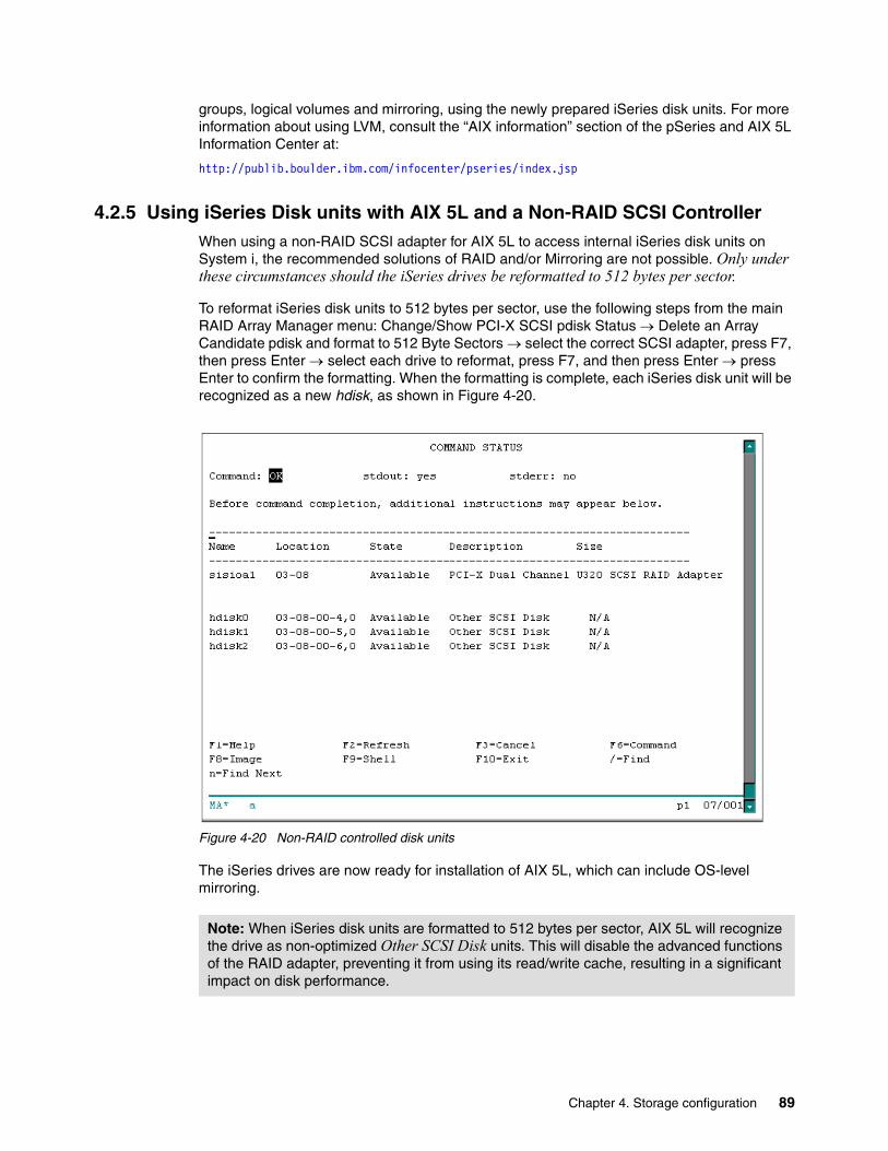
groups, logical volumes and mirroring, using the newly prepared iSeries disk units. For more information about using LVM, consult the “AIX information” section of the pSeries and AIX 5L Information Center at:
http://publib.boulder.ibm.com/infocenter/pseries/index.jsp
4.2.5 Using iSeries Disk units with AIX 5L and a Non-RAID SCSI ControllerWhen using a non-RAID SCSI adapter for AIX 5L to access internal iSeries disk units on System i, the recommended solutions of RAID and/or Mirroring are not possible. Only under these circumstances should the iSeries drives be reformatted to 512 bytes per sector.
To reformat iSeries disk units to 512 bytes per sector, use the following steps from the main RAID Array Manager menu: Change/Show PCI-X SCSI pdisk Status → Delete an Array Candidate pdisk and format to 512 Byte Sectors → select the correct SCSI adapter, press F7, then press Enter → select each drive to reformat, press F7, and then press Enter → press Enter to confirm the formatting. When the formatting is complete, each iSeries disk unit will be recognized as a new hdisk, as shown in Figure 4-20.
Figure 4-20 Non-RAID controlled disk units
The iSeries drives are now ready for installation of AIX 5L, which can include OS-level mirroring.
Note: When iSeries disk units are formatted to 512 bytes per sector, AIX 5L will recognize the drive as non-optimized Other SCSI Disk units. This will disable the advanced functions of the RAID adapter, preventing it from using its read/write cache, resulting in a significant impact on disk performance.
Chapter 4. Storage configuration 89

For a more detailed configuration process, refer to white paper “Using IBM eServer iSeries SCSI Drives with AIX 5L on IBM eServer i5 Systems”, which can be found at:
ftp://ftp.software.ibm.com/common/ssi/rep_wh/n/ISW01522USEN/ISW01522USEN.PDF
90 AIX 5L on the IBM System i Platform: Implementation Guide

Chapter 5. Network configuration
The method for establishing network connectivity for an AIX 5L partition will vary based upon whether the partition will be using a physical or virtual adapter. This chapter presents information about the configuration of network connectivity for AIX 5L on the System i platform.
5
© Copyright IBM Corp. 2005. All rights reserved. 91

5.1 Physical network adaptersAs discussed elsewhere in this book, direct attached (or native) network adapters can be allocated to the logical partition and used by the AIX 5L operating system. Network configuration in such an environment is simply a case of providing the necessary network parameters (TCP/IP address, subnet mask, gateway/router) during the installation of AIX 5L, or using post-installation utilities (that is, SMIT) to configure the network adapter.
5.1.1 AIX 5L physical network adapter allocationWhen allocating a physical network adapter to an AIX 5L partition, it cannot be downstream of a System i I/O Processor (IOP). To determine if an adapter is downstream from an IOP, open the Managed system properties, and go to the I/O tab. Once there, expand the buses to reveal the physical adapters on each bus. The example shown in Figure 5-1, shows a PCI 100/10 Mbps Ethernet adapter in slot C07, and a PCI 1 Gbps Ethernet Fiber 2-port adapter in slot C08, downstream of a PCI I/O Processor (IOP) adapter in slot C06. Because of this, neither adapter can be utilized by an AIX 5L partition.
Figure 5-1 Managed system - I/O properties, Ethernet adapter - IOP
However, when looking at the example shown in Figure 5-2 on page 93, the PCI 10/100/1000 Mbps Ethernet UTP 2-port adapter in slot T5 is not downstream from an IOP adapter, therefore it can be utilized by an AIX 5L partition.
92 AIX 5L on the IBM System i Platform: Implementation Guide

Figure 5-2 Managed system - I/O properties, Ethernet adapter - no IOP
5.2 Virtual network adaptersThis section provides the steps for configuring support in the i5/OS partition for exposing a virtual LAN (VLAN) shared between an i5/OS partition and an AIX 5L partition, to an external network via a physical network adapter allocated to the i5/OS partition.
There are a number of methods for making an AIX 5L partition on a VLAN accessible to an external network, and they include:
� Proxy ARP� Network Address Translation (NAT)
5.2.1 Adding virtual Ethernet adapter to i5/OS partitionRegardless of which method is being used to forward traffic between a physical and virtual network, a VLAN will need to be established between the i5/OS partition and the AIX 5L partition, for the purpose of forwarding the network traffic from the i5/OS partition to the AIX 5L partition.
Note: These instructions are being provided in the event that a virtual network adapter was not previously created for the i5/OS partition. If the adapter has been created, then skip to 5.2.3, “Enable datagram forwarding” on page 103.
Chapter 5. Network configuration 93

Adding virtual adapter to partition profile5. From the HMC, right-click the partition profile and select Properties. The properties
window will be displayed (Figure 5-3). Click the Virtual I/O Adapters tab.
Figure 5-3 Partition profile properties - Virtual I/O selection
6. Click the Ethernet tab to display a list of the already configured virtual Ethernet adapters (Figure 5-4 on page 95).
94 AIX 5L on the IBM System i Platform: Implementation Guide

Figure 5-4 Virtual Ethernet adapters
7. To create a new virtual Ethernet adapter, click Create adapter. This will show the dialog in Figure 5-5 on page 96.
Chapter 5. Network configuration 95
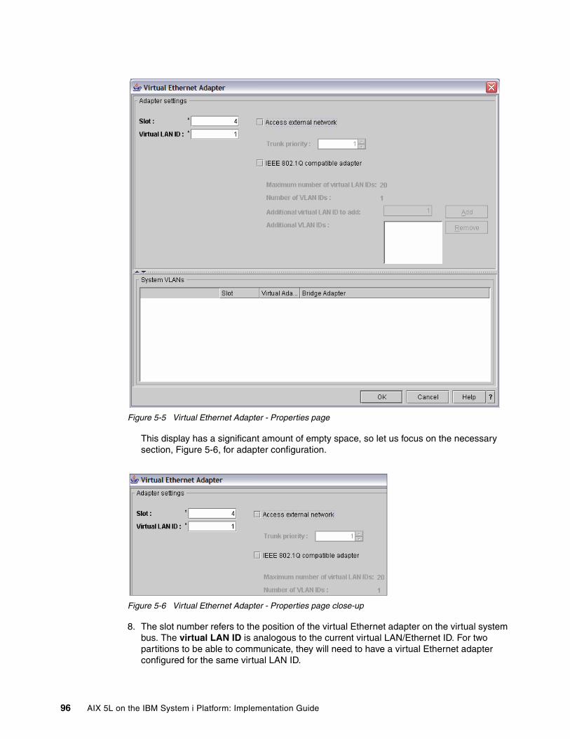
Figure 5-5 Virtual Ethernet Adapter - Properties page
This display has a significant amount of empty space, so let us focus on the necessary section, Figure 5-6, for adapter configuration.
Figure 5-6 Virtual Ethernet Adapter - Properties page close-up
8. The slot number refers to the position of the virtual Ethernet adapter on the virtual system bus. The virtual LAN ID is analogous to the current virtual LAN/Ethernet ID. For two partitions to be able to communicate, they will need to have a virtual Ethernet adapter configured for the same virtual LAN ID.
96 AIX 5L on the IBM System i Platform: Implementation Guide

Having the virtual Ethernet adapter occupy the same slot is not a requirement. The slot number can be left as provided. and enter the Virtual LAN number that corresponds to the virtual LAN that the AIX 5L partition is configured to use. If this is the only VLAN configured on this System i, then it can be left at the default.
9. Once the fields have been completed, click OK.
At this point, the virtual Ethernet adapter has been created (in the partition profile) and the partition profile page will be re-displayed (Figure 5-7) reflecting the new adapter
Figure 5-7 Partition profile properties - Virtual I/O Adapters
10.Click OK to complete the update of the partition profile.
Note: If this virtual Ethernet adapter is going to be used to provide external network connectivity for an AIX 5L partition via a VLAN network, then it will need to be marked as Required.
Note: The following instructions are only applicable if the i5/OS partition cannot be shutdown to allow the partition profile reactivation. If this is not necessary, then skip to 5.2.2, “Creating the Ethernet Line Description in i5/OS” on page 100.
Chapter 5. Network configuration 97

Dynamic addition of the adapter to the i5/OS partitionAdding the adapter to the partition profile means that the next time the partition is activated from the HMC it will have the newly configured adapter. To use the adapter now, it also needs to be added to the partition through the use of Dynamic Logical Partitioning.
1. From the HMC, right-click the i5/OS partition (not the partition profile) and select Dynamic Logical Partitioning → Virtual Adapter Resources → Add/Remove.
The Dynamic Logical Partitioning window for virtual adapters is displayed in Figure 5-8.
Figure 5-8 Dynamic Logical Partitioning - Virtual Adapters
2. Click the Ethernet tab and then click Create Adapter.
3. Complete the fields of the Virtual Ethernet Adapter properties (Figure 5-9 on page 99) and click OK.
98 AIX 5L on the IBM System i Platform: Implementation Guide

Figure 5-9 Virtual Ethernet Adapter - Properties page
The virtual Ethernet adapter is now displayed in the list of adapters for the partition (Figure 5-10 on page 100).
Chapter 5. Network configuration 99

Figure 5-10 Dynamic Logical Partitioning - Virtual Adapters
4. Click OK to update the partition.
At this point the adapter is added to the running partition (Figure 5-11).
Figure 5-11 Dynamic Logical Partitioning - Working dialog
5.2.2 Creating the Ethernet Line Description in i5/OSOnce the Virtual Ethernet adapter has been created for the i5/OS partition, an Ethernet LIne Description will need to be created in i5/OS. A review of the communication hardware resources will help to identify the resource for the line description.
Note: If this virtual Ethernet adapter is going to be used to provide external network connectivity for an AIX 5L partition via a VLAN network, then it will need to be marked as Required.
100 AIX 5L on the IBM System i Platform: Implementation Guide
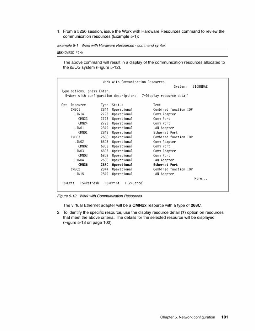
1. From a 5250 session, issue the Work with Hardware Resources command to review the communication resources (Example 5-1):
Example 5-1 Work with Hardware Resources - command syntax
WRKHDWRSC *CMN
The above command will result in a display of the communication resources allocated to the i5/OS system (Figure 5-12).
Figure 5-12 Work with Communication Resources
The virtual Ethernet adapter will be a CMNxx resource with a type of 268C.
2. To identify the specific resource, use the display resource detail (7) option on resources that meet the above criteria. The details for the selected resource will be displayed (Figure 5-13 on page 102).
Work with Communication Resources System: S10B8DAE Type options, press Enter. 5=Work with configuration descriptions 7=Display resource detail Opt Resource Type Status Text CMB01 2844 Operational Combined function IOP LIN14 2793 Operational Comm Adapter CMN23 2793 Operational Comm Port CMN24 2793 Operational Comm Port LIN01 2849 Operational LAN Adapter CMN01 2849 Operational Ethernet Port CMB03 268C Operational Combined function IOP LIN02 6B03 Operational Comm Adapter CMN02 6B03 Operational Comm Port LIN03 6B03 Operational Comm Adapter CMN03 6B03 Operational Comm Port LIN04 268C Operational LAN Adapter CMN36 268C Operational Ethernet Port CMB02 2844 Operational Combined function IOP LIN15 2849 Operational LAN Adapter More... F3=Exit F5=Refresh F6=Print F12=Cancel
Chapter 5. Network configuration 101
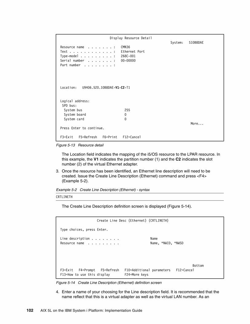
Figure 5-13 Resource detail
The Location field indicates the mapping of the i5/OS resource to the LPAR resource. In this example, the V1 indicates the partition number (1) and the C2 indicates the slot number (2) of the virtual Ethernet adapter.
3. Once the resource has been identified, an Ethernet line description will need to be created. Issue the Create Line Description (Ethernet) command and press <F4> (Example 5-2).
Example 5-2 Create Line Description (Ethernet) - syntax
CRTLINETH
The Create Line Description definition screen is displayed (Figure 5-14).
Figure 5-14 Create Line Description (Ethernet) definition screen
4. Enter a name of your choosing for the Line description field. It is recommended that the name reflect that this is a virtual adapter as well as the virtual LAN number. As an
Display Resource Detail System: S10B8DAE Resource name . . . . . . . : CMN36 Text . . . . . . . . . . . . : Ethernet Port Type-model . . . . . . . . . : 268C-001 Serial number . . . . . . . : 00-00000 Part number . . . . . . . . : Location: U9406.520.10B8DAE-V1-C2-T1 Logical address: SPD bus: System bus 255 System board 0 System card 0 More... Press Enter to continue. F3=Exit F5=Refresh F6=Print F12=Cancel
Create Line Desc (Ethernet) (CRTLINETH) Type choices, press Enter. Line description . . . . . . . . Name Resource name . . . . . . . . . Name, *NWID, *NWSD
Bottom F3=Exit F4=Prompt F5=Refresh F10=Additional parameters F12=Cancel F13=How to use this display F24=More keys
102 AIX 5L on the IBM System i Platform: Implementation Guide

example, for a virtual LAN adapter on virtual LAN 1, a name like VRTETH01 might be appropriate.
5. Enter the communication resource (CMNxx) identified as the resource that maps to the virtual Ethernet adapter for the Resource name field.
6. Once the first two fields have been completed, press Enter to display additional fields (Figure 5-15).
Figure 5-15 Create Line Description (Ethernet) definition screen - additional fields
7. The setting of the Line speed field will be dependent on the line speed of the physical interface. The line speed should be set to match the line speed of any associated physical interface to avoid fragmentation of the network packets.
8. The setting of Duplex is typically set to *FULL.
9. Once the fields have been completed press Enter.
10.Additional fields will be displayed. Press Enter again to complete the definition.
11.Once the line description has been created, vary it on (Example 5-3).
Example 5-3 VRYCFG command syntax
VRYCFG CFGOBJ(VRTETH01) CFGTYPE(*LIN) STATUS(*ON)
5.2.3 Enable datagram forwardingFor all three approaches (Proxy ARP, NAT, and TCP routing) the TCP/IP attribute Datagram forwarding will need to be enabled. Datagram forwarding allows network packets to be forwarded between network interfaces on the system.
1. To ensure that datagram forwarding is enabled, issue the following command (Example 5-4 on page 103).
Example 5-4 CHGTCPA command syntax
CHGTCPA IPDTGFWD(*YES)
Create Line Desc (Ethernet) (CRTLINETH) Type choices, press Enter. Line description . . . . . . . . > VRTETH01 Name Resource name . . . . . . . . . > CMN36 Name, *NWID, *NWSD Online at IPL . . . . . . . . . *YES *YES, *NO Vary on wait . . . . . . . . . . *NOWAIT *NOWAIT, 15-180 seconds Local adapter address . . . . . *ADPT 020000000000-FEFFFFFFFFFF... Exchange identifier . . . . . . *SYSGEN 05600000-056FFFFF, *SYSGEN Ethernet standard . . . . . . . *ALL *ETHV2, *IEEE8023, *ALL Line speed . . . . . . . . . . . 10M 10M, 100M, 1G, *AUTO Duplex . . . . . . . . . . . . . *HALF *HALF, *FULL, *AUTO
Bottom F3=Exit F4=Prompt F5=Refresh F10=Additional parameters F12=Cancel F13=How to use this display F24=More keys
Chapter 5. Network configuration 103

5.2.4 Proxy ARPProxy ARP is used to build a subnet within the overall network that the i5/OS partition’s physical network interface is connected to. Essentially, i5/OS becomes a router for a subnet of address that will be assigned to the virtual LAN. An example environment that will use Proxy ARP is shown in Figure 5-16.
Figure 5-16 Proxy ARP example
In this example, a subnet is established that ranges from 10.1.1.24 to 10.1.1.31. This range of addresses is assigned to the virtual LAN and is associated with an interface on the physical LAN (in this case 10.1.1.3) to act as the router for the subnet. The range of addresses for the subnet is determined by an address in the network along with the subnet mask. There are a number of rules that the subnet must meet:
� The size of the subnet must be a power of 2.
� The first address of the subnet cannot be assigned to a partition. The first address is the network address.
� The last address of the subnet cannot be assigned to partition. The last address is the broadcast address.
� The subnet must be contained wholly within the overall network that the associated i5/OS physical network is attached to.
Highlights of the Proxy ARP environment can be summarized as follows:
� Traffic intended for partitions on the virtual LAN is “routed” to the i5/OS physical network interface.
� Traffic is then re-broadcast on the virtual LAN via the i5/OS connection on that LAN.
� The AIX 5L operating system running in the partition “sees” the network traffic just like in any other network structure.
� DNS entries point to the address on the virtual LAN.
10.1.1.10 10.1.1.11
10.1.1.12
10.1.1.13
Subnet mask255.255.255.0
i5/OSPar ID 1
AIXPar ID 2
LinuxPar ID 3
ProxyARP
VLAN1 Addrs – 10.1.1.25 – 10.1.1.30Subnet mask 255.255.255.248
104 AIX 5L on the IBM System i Platform: Implementation Guide

� Virtual LAN address range must be a subset of the physical LAN addresses.
� The virtual LAN MTU (frame size) should be equal to or less than that of the physical LAN.
The following steps walk through setup of the components in i5/OS to support Proxy ARP.
Determining range of TCP/IP addresses to Proxy As indicated earlier, Proxy ARP is the establishment of a range of addresses that will be associated with a single physical interface. A subnet calculator is a good tool to help determine a range of addresses for the subnet.
One example is the IP Subnet Calculator from WildPackets, Inc. (http://www.wildpackets.com/products/free_utilities/ipsubnetcalc/overview)
Building on the example shown earlier, the subnet calculator could be used to establish the range of addresses as shown in Figure 5-17.
Figure 5-17 Subnet Calculator
In this example, an address was specified that should fall within the range of addresses for the subnet, and the subnet mask specified indicates the size of the subnet (that is, 255.255.255.248 indicates a subnet of 8 addresses).
By specifying the above values a subnet is defined with the following characteristics:
� Network Address 10.1.1.24� Range of usable addresses 10.1.1.25 - 10.1.1.30� Broadcast Address 10.1.1.31
Note: These steps assume that the i5/OS partition and AIX 5L partition have already been defined with virtual Ethernet adapters on the same VLAN, and the Ethernet Line description has been created and is active.
Chapter 5. Network configuration 105

Now that the subnet range has been defined, the next step will be to create the TCP/IP interface for i5/OS on the virtual LAN.
Create TCP/IP interface for virtual LAN adapterOnce the Ethernet Line Description has been created, and the subnet defined, you are ready to define the TCP/IP interface for i5/OS on the virtual LAN.
1. Issue the Add TCP/IP Interface command to create the TCP/IP interface (Example 5-5).
Example 5-5 ADDTCPIFC syntax
ADDTCPIFC INTNETADR(‘10.1.1.25’) LIND(VRTETH01) SUBNETMASK(‘255.255.255.248’) LCLIFC(‘10.1.1.3’)
Where:
• Value of INTNETADR is the address of the i5/OS interface on the virtual LAN
• Value for LIND is the name of the Ethernet Line Description for the virtual LAN
• Value for SUBNETMASK is the size of the subnet
• Value for LCLIFC is the address of the physical network interface in i5/OS that will forward traffic to the virtual LAN
You could also prompt the ADDTCPIFC command (that is, press <F4>) and complete the fields (Figure 5-18 on page 106).
Figure 5-18 Add TCP/IP Interface
2. Once the TCP/IP interface has been created it can be varied on with the Start TCP/IP Interface command (Example 5-6).
Note: Typically i5/OS will be assigned the first usable address in the subnet.
Add TCP/IP Interface (ADDTCPIFC) Type choices, press Enter. Internet address . . . . . . . . 10.1.1.25 Line description . . . . . . . . VRTETH01 Name, *LOOPBACK... Subnet mask . . . . . . . . . . 255.255.255.248 Alias name . . . . . . . . . . . *NONE Associated local interface . . . 10.1.1.3 Type of service . . . . . . . . *NORMAL *MINDELAY, *MAXTHRPUT... Maximum transmission unit . . . *LIND 576-16388, *LIND Autostart . . . . . . . . . . . *YES *YES, *NO PVC logical channel identifier 001-FFF + for more values X.25 idle circuit timeout . . . 60 1-600 X.25 maximum virtual circuits . 64 0-64 X.25 DDN interface . . . . . . . *NO *YES, *NO TRLAN bit sequencing . . . . . . *MSB *MSB, *LSB Bottom F3=Exit F4=Prompt F5=Refresh F12=Cancel F13=How to use this display F24=More keys
106 AIX 5L on the IBM System i Platform: Implementation Guide

Example 5-6 STRTCP syntax
STRTCPIFC INTNETADR(‘10.1.1.25’)
AIX 5L network attributesAt this point the i5/OS setup to support Proxy ARP is complete. When AIX 5L is installed, the network parameters will be configured as follows:
� TCP/IP Address: An available address within the usable range of addresses for the subnet.
� Subnet mask: The size of the subnet (should be the same value as used for the TCP/IP interface in i5/OS for the subnet.)
� Router/Gateway: The address of the i5/OS VLAN interface.
The following diagram (Figure 5-19 on page 107) represents a completely defined Proxy ARP environment.
Figure 5-19 Proxy ARP - Example
In the above example, a range of addresses (10.1.1.25 - 10.1.1.30) is assigned to the virtual LAN. Additionally, the address for i5/OS on the virtual LAN (10.1.1.25) is associated with the i5/OS’s address on the physical LAN (10.1.1.3) which provides the forwarding of traffic between the virtual and physical network.
5.2.5 Network Address TranslationNetwork Address Translation (NAT) is used to map a public address to a private address. With NAT, a private network is established between the AIX 5L and i5/OS partitions and a mapping of public to private address is established. An example environment that will use NAT is shown in Figure 5-20 on page 108.
Hypervisor
External NetworkEthernet Switch
Physicaladapter
I5/OS host Partition 1 Client AIXPartition 2
Client AIXPartition 3Proxy Arp
VLAN=1
VLAN 110.1.1.x255.255.255.248
Physical Network10.1.1.x255.255.255.0
10.1.1.27255.255.255.248
10.1.1.26255.255.255.248
10.1.1.25255.255.255.248
10.1.1.3255.255.255.0
Vrt eth(CMNxx)
Vrt eth(entx)
Vrt eth(entx)
Chapter 5. Network configuration 107

Figure 5-20 Network Address Translation Example
In this example, the AIX 5L partitions are assigned public address (10.1.101 and 10.1.154) which are mapped to private address (172.168.1.2 and 172.168.1.3) through the NAT support within i5/OS.
Highlights of the NAT environment can be summarized as follows:
� Addresses for each of the LPARs are defined in the partition providing NAT service (that is, i5/OS partition).
This address becomes an additional address on the physical adapter.
� Static NAT rules are defined to map the public (physical) address to the private (virtual LAN) address
� DNS entries will point to the public (physical) addresses
� The physical network adapter replies to the network request
� The IP address in the IP header is rewritten (mangled) to reflect the private address.
� The routing table is checked and the network traffic is forwarded to the destination
� Output traffic from the private LAN is routed through the proxying (that is, i5/OS) partition.
The following sections walk through setup of the components in i5/OS to support NAT.
Note: The i5/OS partition’s virtual LAN interface will be assigned an address within the private network range (normally the first usable address) however the address will not be mapped to a public address.
10.1.1.10 10.1.1.11
10.1.1.12
10.1.1.1310.1.1.10110.1.1.154
Subnet mask255.255.255.0
i5/OSPar ID 1
AIXPar ID 2
AIX2Par ID 3
Public
VLAN1 Addrs – 172.168.1.1 – 172.168.1.254Subnet mask 255.255.255.0
Map 10.1.1.101 <-> 172.168.1.2Map 10.1.1.154 <-> 172.168.1.3
Private
108 AIX 5L on the IBM System i Platform: Implementation Guide

Create TCP/IP interface for i5/OS on virtual LANA TCP/IP interface needs to be created for the i5/OS partition on the virtual LAN. This is the interface that will be used to forward traffic between the virtual and physical networks. Four aspects of this TCP/IP interface to keep in mind:
� The TCP/IP address assigned to the interface needs to be one of the addresses in the private network. Typically the address assigned will be the first usable address in the private network.
� Unlike the private addresses for the AIX 5L partitions, the private address assigned to the i5/OS partition will not be mapped to a public address.
� The i5/OS address on the VLAN will be used by the AIX 5L partitions as their router/gateway.
� The TCP/IP interface on the VLAN will be associated with the TCP/IP interface on the physical LAN.
1. Issue the Add TCP/IP Interface command to create the TCP/IP interface (Example 5-7).
Example 5-7 ADDTCPIFC command syntax
ADDTCPIFC INTNETADR(‘172.168.1.1’) LIND(VRTETH01) SUBNETMASK(‘255.255.255.0’) LCLIFC(‘10.1.1.3’)
Where:
– Value of INETADR is the address of the i5/OS interface on the VLAN
– Value for LIND is the name of the Ethernet Line Description for the VLAN
– Value for SUBNETMASK is the size of the subnet
– Value for LCLIFC is the address of the physical network interface in i5/OS that will forward traffic to the VLAN.
2. Once the TCP/IP interface has been created it can be varied on with the Start TCP/IP Interface command (Example 5-8).
Example 5-8 STRTCPIFC command syntax
STRTCPIFC INTNETADR(‘172.168.1.1’)
Create TCP/IP interfaces for public addressesEach partition that will have their network traffic coming and going through NAT needs to have a TCP/IP interface created for its public address, against the i5/OS physical Ethernet Line Description that will handle the network traffic.
1. For each public address, use the Add TCP/IP Interface command to create the TCP/IP interface (Example 5-9).
Example 5-9 ADDTCPIFC syntax
ADDTCPIFC INETADR(‘10.1.1.101’) LIND(ETHLINC05) SUBNETMASK(‘255.255.255.0’)
Where:
Note: These steps assume that the i5/OS partition and AIX 5L partition have already been defined with virtual Ethernet adapters on the same VLAN. Additionally, these steps assume that the Ethernet Line Description for the i5/OS partitions VLAN connection has been created, is active, and TCP/IP Datagram Forwarding has been enabled.
Chapter 5. Network configuration 109
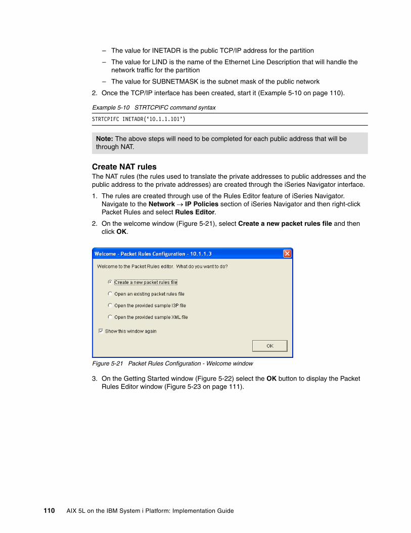
– The value for INETADR is the public TCP/IP address for the partition
– The value for LIND is the name of the Ethernet Line Description that will handle the network traffic for the partition
– The value for SUBNETMASK is the subnet mask of the public network
2. Once the TCP/IP interface has been created, start it (Example 5-10 on page 110).
Example 5-10 STRTCPIFC command syntax
STRTCPIFC INETADR(‘10.1.1.101’)
Create NAT rulesThe NAT rules (the rules used to translate the private addresses to public addresses and the public address to the private addresses) are created through the iSeries Navigator interface.
1. The rules are created through use of the Rules Editor feature of iSeries Navigator. Navigate to the Network → IP Policies section of iSeries Navigator and then right-click Packet Rules and select Rules Editor.
2. On the welcome window (Figure 5-21), select Create a new packet rules file and then click OK.
Figure 5-21 Packet Rules Configuration - Welcome window
3. On the Getting Started window (Figure 5-22) select the OK button to display the Packet Rules Editor window (Figure 5-23 on page 111).
Note: The above steps will need to be completed for each public address that will be through NAT.
110 AIX 5L on the IBM System i Platform: Implementation Guide

Figure 5-22 Packet Rules Editor - Getting Started
Figure 5-23 Packet Rules Editor
4. From the Packet Rules Editor select Wizards from the menu bar and then select Address Translation.
5. On the Address Translation Wizard Welcome window (Figure 5-24 on page 112) click Next.
Chapter 5. Network configuration 111
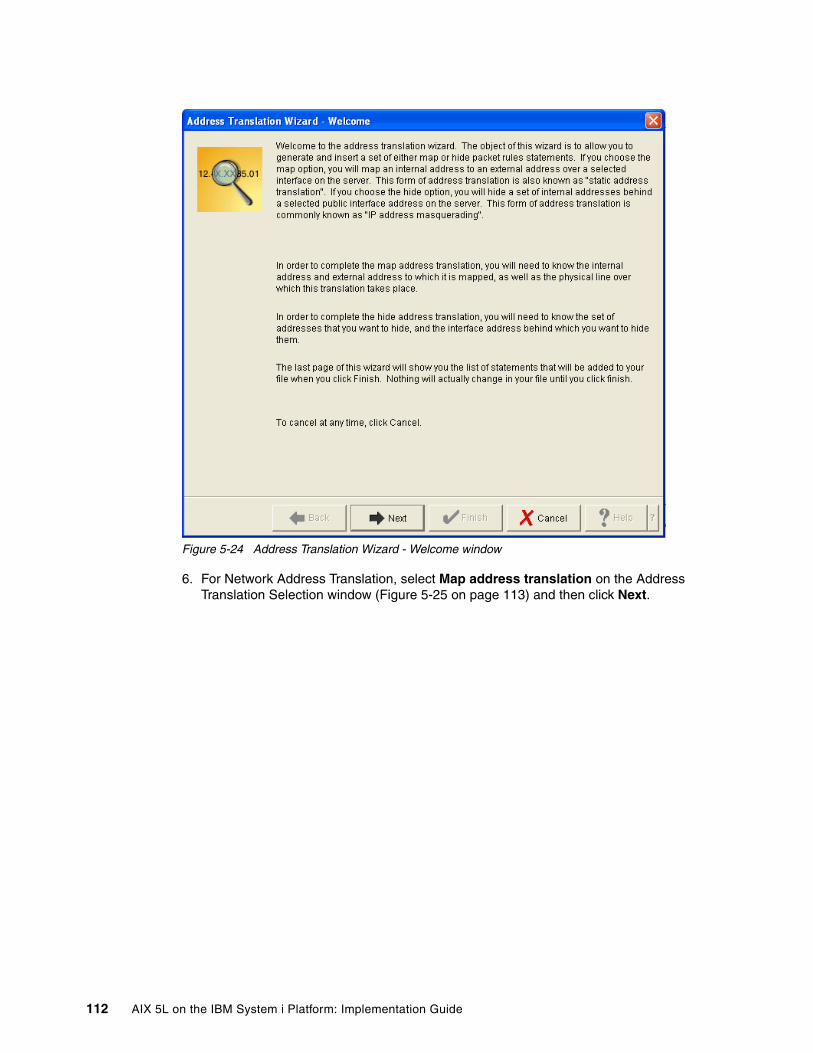
Figure 5-24 Address Translation Wizard - Welcome window
6. For Network Address Translation, select Map address translation on the Address Translation Selection window (Figure 5-25 on page 113) and then click Next.
112 AIX 5L on the IBM System i Platform: Implementation Guide

Figure 5-25 Address Translation Selection
7. On the Private Address window (Figure 5-26 on page 114) enter the private TCP/IP address (the TCP/IP address for the interface on the VLAN) for the AIX 5L partition. Once the TCP/IP address as been specified, click Next.
Chapter 5. Network configuration 113

Figure 5-26 Packet Rules Editor - Private Address
8. On the Public Address window (Figure 5-27 on page 115) enter the TCP/IP address that will be used by the external network to access the AIX 5L partition (that is, the AIX 5L partitions public address). Once the TCP/IP address has been specified, click Next.
114 AIX 5L on the IBM System i Platform: Implementation Guide

Figure 5-27 Packet Rules Editor - Public Address
9. On the Line window (Figure 5-28 on page 116), select the interface that will be used for the AIX 5L partitions network traffic. The interface is the i5/OS line description for the physical network adapter connected to the external LAN. Once the line description has been selected, click Next.
Chapter 5. Network configuration 115

Figure 5-28 Packet Rules Editor - Line Selection
10.Finally a summary window is displayed (Figure 5-29 on page 117). Select the Finish button to cause the rules to be generated.
116 AIX 5L on the IBM System i Platform: Implementation Guide

Figure 5-29 Packet Rules Editor - Summary
11.Once the rules have been generated they will be displayed in the Packet Rules Editor window. The rules will need to be saved before they can be activated and used. To save the rules, select File from the menu bar and then select Save As.
12.On the Save File window (Figure 5-30 on page 118) specify a file name for the packet rules. Ensure that the Type is left as I3P files and select the Save button.
Note: Remember to create an address translation rule for each public address that needs to be translated to a private address.
Chapter 5. Network configuration 117

Figure 5-30 Packet Rules Editor - Save File
13.To activate the newly created rules, select File from the menu bar and then select Activate Rules.
14.On the Activate Packet Rules window (Figure 5-31) leave the selections at the defaults and click the OK button. As a point of reference, here are the correct settings:
– Packet rules files: Activate both VPN generated rules and selected file.
– File name: Name of NAT rules just saved.
– Interface: Activate these rules on all interfaces and all point-to-point identifiers.
Figure 5-31 Activate Packet Rules
118 AIX 5L on the IBM System i Platform: Implementation Guide

15.A message indicating that the rules have been activated will be displayed at the bottom of the Packet Rules Editor window.
AIX 5L network settingsAll that is left is to configure network settings for the AIX 5L partition. The primary tool used to configure network interfaces in AIX 5L is ifconfig. The network parameters to be configured for the AIX 5L partition are as follows:
� TCP/IP Address: The VLAN network address for the AIX 5L partition. This is the address assigned as the “private” address in the NAT rules.
� Subnet Mask: The subnet mask assigned to the VLAN (typically set to 255.255.255.0). This is the same subnet mask assigned to the i5/OS’s interface on the VLAN.
� Router/Gateway: The address of the i5/OS partitions VLAN connection.
The following diagram (Figure 5-32) represents a completely defined NAT environment:
Figure 5-32 NAT - Example
In the above example, a range of addresses (172.168.1.1 - 172.168.1.254) has been assigned to the VLAN, and public addresses (10.1.1.101 and 10.1.1.154) for the partitions have been assigned to the i5/OS physical interface. Additionally, NAT rules have been established that translate the public (physical network) addresses to the private (Virtual Network) addresses.
5.2.6 Other approachesIn addition to Network Address Translation and Proxy ARP via i5/OS, there are other alternatives to exposing partitions on a VLAN to external network traffic. While not covered in detail in this book, these methods include:
� Proxy ARP via a Linux partition� Direct Routing
External Network
Physicaladapter
I5/OS host Partition 1 Client AIXPartition 2
Client AIXPartition 3
NAT
Hypervisor VLAN=1
VLAN 1172.168.1.x255.255.255.0
Physical Network10.1.1.x255.255.255.0
172.168.1.3172.168.1.2172.168.1.1
10.1.1.3
10.1.1.101
10.1.1.254
Ethernet Switch
Vrt eth(CMNxx)
Vrt eth(entx)
Vrt eth(entx)
Chapter 5. Network configuration 119
Proxy ARP via Linux involves a Linux partition with both a physical network connection as well as a virtual network connection to other partitions. This method involves the establishment of direct routing statements to the IP addresses of the partitions on the VLAN and, like Proxy ARP in i5/OS, the Linux partition acting as the proxy responds to the IP addresses for the other partitions, making the network traffic available on the VLAN.
Direct routing is also known as TCP/IP routing. Standard TCP/IP routing is used to route traffic to the virtual Ethernet network in the same way you define routing to any other LAN. This requires that you update routing information throughout your network.
This will require reconfiguration of the LAN routers connected to the System i. In this method, route statements are configured in the LAN router, that directs traffic for the VLAN TCP/IP addresses, to the i5/OS interface on the physical LAN. Like the Proxy ARP solutions, the DNS entries in the network will point to the addresses on the VLAN. When traffic for one of the TCP/IP addresses on the VLAN is seen by the physical router, it consults its route table for the destination, then forwards the traffic to that destination (in this case the i5/OS physical network adapter). Outbound traffic (that is, traffic going out from the partitions on the VLAN) direct their traffic to the i5/OS partitions interface on the VLAN (the same way they do for the Proxy ARP and NAT solutions).
120 AIX 5L on the IBM System i Platform: Implementation Guide

Chapter 6. AIX 5L installation
This chapter covers the additional installation options for installing AIX 5L on a System i partition.
6
Note: Network Installation Manager (NIM) is also a very popular installation method of AIX 5L. We do not describe this method of installation in our book, because this installation method is the same for System i. For more information about NIM, refer to:
http://publib.boulder.ibm.com/infocenter/pseries/v5r3/topic/com.ibm.aix.install/doc/insgdrf/insgdrf.pdf
© Copyright IBM Corp. 2005. All rights reserved. 121
6.1 New virtual CD-ROM installation processStarting with AIX 5L 5.3.00.30, AIX 5L is able to recognize, and utilize, virtual CD/DVD units. This is a change from previous releases of AIX 5L.
This significant change means that it is no longer necessary to allocate a physical device to the AIX 5L partition.
6.1.1 RequirementsTo use virtual CD-ROM for AIX 5L installation, the following requirements must be met:
� AIX 5L 5.3 with maintenance package 5300-03, or newer.
� Virtual SCSI server and client adapters configured for the appropriate partitions, and cross-referenced correctly.
� A minimum of one i5/OS Network Server Description (NWSD), properly configured to point to the AIX 5L partition.
� A physical CD/DVD drive allocated to the i5/OS partition, and in an ACTIVE state.
6.1.2 ProcessTo install AIX 5L from a virtual CD/DVD, the following parameters must be set if the i5/OS partition is configured as the Power Controlling partition of the AIX 5L partition:
� The AIX 5L partition profile boot mode must be set to System Management Services (SMS).
� The IPL Source (IPLSRC) parameter on the NWSD must be set to *PANEL, and the Power Control (PWRCTL) parameter must be set to *YES.
With these settings configured correctly, open a terminal window for the AIX 5L partition, then vary on the NWSD from a separate 5250 emulation session.
When the partition activates, it will go to Open Firmware and the following screen, Figure 6-1 on page 123, will be displayed.
Note: i5/OS virtual CD drives may also be used as source drives, but this has not been investigated for this book.
122 AIX 5L on the IBM System i Platform: Implementation Guide

Figure 6-1 SMS Main menu
Select option 1 to select install/boot device. This will bring up the screen shown in Figure 6-2 on page 124.
Chapter 6. AIX 5L installation 123

Figure 6-2 SMS - Select install/boot device
Select option 7, List all devices on this screen. This will bring up a screen similar to Figure 6-3 on page 125.
124 AIX 5L on the IBM System i Platform: Implementation Guide

Figure 6-3 SMS - List all boot devices
This will show all possible boot devices available to this partition. In this example, we can see that the virtual CD-ROM drive is device #3, so we will choose #3, which will bring up the screen shown in Figure 6-4 on page 126.
Chapter 6. AIX 5L installation 125

Figure 6-4 SMS - Select Boot mode
To perform an installation of AIX 5L, select option 2, which will present the following screen of Figure 6-5 on page 127.
126 AIX 5L on the IBM System i Platform: Implementation Guide

Figure 6-5 SMS - exit SMS prompt
Answering Yes to this prompt will exit SMS.
At this time, you may skip to 6.2.2, “AIX 5L operating system installation” on page 131 to go through the AIX 5L installation process, but will need to return to perform the Post install changes.
Post install changesAfter AIX 5L has been successfully installed, the following changes will need to be made to the partition profile and the NWSD after the NWSD has been varied off:
� The Boot Mode on the partition profile will need to be changed back to Normal.
� The IPL Source (IPLSRC) parameter on the NWSD must be changed to *NWSSTG’ if using virtual disk drives. If using native disk drive units, and no virtual disk drives, then change the Power Control (PWRCTL) parameter to *NO and the NWSD can be left varied off, or even deleted from the system, if desired.
6.2 Physical CD-ROM installationIn this procedure, you will perform a new and complete base operating system installation on a logical partition using a physical CD-ROM device allocated to the partition.
This procedure assumes that a partition profile has already been created, and a SCSI bus controller for a CD-ROM device has been allocated to the partition.
Chapter 6. AIX 5L installation 127

Set the boot mode for this partition to be SMS mode.
6.2.1 Physical CD-ROM boot device selectionTo start the installation of AIX 5L from a physical CD, insert the AIX 5L Volume 1 CD into the managed CD device and activate the partition profile to boot to SMS mode.
1. After activating the AIX 5L partition, the opening system console appears as shown in Figure 6-6. Select 5. Select Boot Options and press Enter.
Figure 6-6 SMS menu
2. Select Install /Boot Device as shown in Figure 6-7, and press Enter.
Figure 6-7 Selecting Install/Boot Device
3. Select option 3. CD/DVD as shown in Figure 6-8 on page 129, and press Enter.
Note: Do not forget to mark the Open terminal window or console session field in Activate Logical Partition window.
Version SF220_013SMS 1.5 (c) Copyright IBM Corp. 2000,2003 All rights reserved.-------------------------------------------------------------------------------Main Menu 1. Select Language 2. Setup Remote IPL (Initial Program Load) 3. Change SCSI Settings 4. Select Console 5. Select Boot Options
-------------------------------------------------------------------------------Navigation Keys:
X = eXit System Management Services-------------------------------------------------------------------------------Type the number of the menu item and press Enter or select Navigation Key:5
Version SF220_013SMS 1.5 (c) Copyright IBM Corp. 2000,2003 All rights reserved.------------------------------------------------------------------------------- 1. Select Install/Boot Device 2. Configure Boot Device Order 3. Multiboot Startup <OFF>
-------------------------------------------------------------------------------Navigation keys:M = return to Main MenuESC key = return to previous screen X = eXit System Management Services-------------------------------------------------------------------------------Type the number of the menu item and press Enter or select Navigation Key:1
128 AIX 5L on the IBM System i Platform: Implementation Guide

Figure 6-8 Selecting CD/DVD as installation device
4. Select option 6. List All Devices as shown in Figure 6-9, and press Enter.
Figure 6-9 Selecting media type
5. Select the menu number of the media type that corresponds to the CD-ROM device and press Enter. In the example shown in Figure 6-10 on page 130, the physical CD-ROM device is device 5.
Version SF220_013SMS 1.5 (c) Copyright IBM Corp. 2000,2003 All rights reserved.-------------------------------------------------------------------------------Select Device Type 1. Diskette 2. Tape 3. CD/DVD 4. IDE 5. Hard Drive 6. Network 7. List all Devices
-------------------------------------------------------------------------------Navigation keys:M = return to Main MenuESC key = return to previous screen X = eXit System Management Services-------------------------------------------------------------------------------Type the number of the menu item and press Enter or select Navigation Key:3
Version SF220_013SMS 1.5 (c) Copyright IBM Corp. 2000,2003 All rights reserved.-------------------------------------------------------------------------------Select Media Type 1. SCSI 2. SSA 3. SAN 4. IDE 5. ISA 6. List All Devices
-------------------------------------------------------------------------------Navigation keys:M = return to Main MenuESC key = return to previous screen X = eXit System Management Services-------------------------------------------------------------------------------Type the number of the menu item and press Enter or select Navigation Key:6
Chapter 6. AIX 5L installation 129

Figure 6-10 Choosing source of installation media
6. Choose option 2. Normal Mode Boot and press Enter as shown in Figure 6-11.
Figure 6-11 Choosing boot mode
7. Type 1 and press Enter to exit from SMS as shown in Figure 6-12 on page 131.
Version SF220_013SMS 1.5 (c) Copyright IBM Corp. 2000,2003 All rights reserved.-------------------------------------------------------------------------------Select DeviceDevice Current DeviceNumber Position Name 1. - Virtual Ethernet ( loc=U9406.520.108A36C-V2-C2-T1 ) 2. - SCSI CD-ROM ( loc=U9406.520.108A36C-V2-C3-T1-W8020000000000000-L0 ) 3. - SCSI Tape ( loc=U9406.520.108A36C-V2-C3-T1-W8040000000000000-L0 ) 4. - SCSI Tape ( loc=U9406.520.108A36C-V2-C3-T1-W8140000000000000-L0 ) 5. - SCSI CD-ROM ( loc=U5095.001.103294C-CB1-C07-T1-L1-L0 )
-------------------------------------------------------------------------------Navigation keys:M = return to Main MenuESC key = return to previous screen X = eXit System Management Services-------------------------------------------------------------------------------Type the number of the menu item and press Enter or select Navigation Key:5
SMS 1.5 (c) Copyright IBM Corp. 2000,2003 All rights reserved.-------------------------------------------------------------------------------Select Task
SCSI CD-ROM ( loc=U5095.001.103294C-CB1-C07-T1-L1-L0 )
1. Information 2. Normal Mode Boot 3. Service Mode Boot
-------------------------------------------------------------------------------Navigation keys:M = return to Main MenuESC key = return to previous screen X = eXit System Management Services-------------------------------------------------------------------------------Type the number of the menu item and press Enter or select Navigation Key:2
130 AIX 5L on the IBM System i Platform: Implementation Guide
Figure 6-12 Exiting SMS
6.2.2 AIX 5L operating system installationShortly your system will start booting from the installation media as shown in Figure 6-13, and finally you get the screen as shown in Figure 6-14 on page 132.
Figure 6-13 Booting process of AIX 5L from CD
1. Type 1 and press Enter to use this terminal as the system console and wait some time for the next screen as shown in Figure 6-14 on page 132.
Version SF220_013SMS 1.5 (c) Copyright IBM Corp. 2000,2003 All rights reserved.-------------------------------------------------------------------------------Are you sure you want to exit System Management Services? 1. Yes 2. No
-------------------------------------------------------------------------------Navigation Keys:
X = eXit System Management Services-------------------------------------------------------------------------------Type the number of the menu item and press Enter or select Navigation Key:1
rtas_call_lock : 0x000000000787b240 8 29 0debug_trace_point : 0x00000000078784c0 8 30 0last_error_log : 0x000000000789f140 2048 30 0rpc_buffer : 0x00000000078b5000 4096 30 12partfw_error_log : 0x00000000078b8000 2048 30 0bufferstatus : 0x0000000007879980 40 30 1pending_flag : 0x000000000787b0c0 8 30 0event_scan_data : 0x00000000078b7000 2024 31 12rtas_call_buf_trace : 0x00000000078c2000 8208 31 12perf_tools_buff : 0x00000000078c5000 88 31 12nmi_work_buffer : 0x00000000078c6000 4096 31 12get_cfg_mgr_receipt : 0x0000000007879ac0 8 31 0SPLPAR info: entitled_capacity: 20 platcpus_active: 2This system is SMT enabled: smt_status: 00000007; smt_threads: 2 kernel size: 10595290; 32 bit kernel kernel debugger setting: enabled-------------------------------------------------------------------------------
AIX Version 5.3Starting NODE#000 physical CPU#001 as logical CPU#001... done.Starting NODE#000 physical CPU#002 as logical CPU#002... done.Starting NODE#000 physical CPU#003 as logical CPU#003... done.
Chapter 6. AIX 5L installation 131

Figure 6-14 Choosing terminal
2. Select the appropriate language to use during the install. In the example shown in Figure 6-15, English has been selected.
Figure 6-15 Choosing English language
3. In the Welcome to Base Operating System Installation and Maintenance menu choose option 2 to select Change/Show Installation Settings an Install as shown on Figure 6-16 on page 133 and press Enter.
Preserving 84314 bytes of symbol table [vscsi_initdd32]
******* Please define the System Console. *******
Type a 1 and press Enter to use this terminal as the system console.Pour definir ce terminal comme console systeme, appuyez sur 1 puis sur Entree.Taste 1 und anschliessend die Eingabetaste druecken, um diese Datenstation als Systemkonsole zu verwenden.Premere il tasto 1 ed Invio per usare questo terminal come console.Escriba 1 y pulse Intro para utilizar esta terminal como consola del sistema.Escriviu 1 1 i premeu Intro per utilitzar aquest terminal com a consola del sistema.Digite um 1 e pressione Enter para utilizar este terminal como console do sistema.
>>> 1 Type 1 and press Enter to have English during install. 2 Entreu 2 i premeu Intro per veure la instal·lació en catalr. 3 Entrez 3 pour effectuer l'installation en français. 4 Für Installation in deutscher Sprache 4 eingeben und die Eingabetaste drücken. 5 Immettere 5 e premere Invio per l'installazione in Italiano. 6 Digite 6 e pressione Enter para usar Portugues na instalaçao. 7 Escriba 7 y pulse Intro para la instalación en espanol.
88 Help ?
>>> Choice [1]: 1
132 AIX 5L on the IBM System i Platform: Implementation Guide

Figure 6-16 Installation and Maintenance
4. Type 1 to display or change on which disk drive(s) to install operating system as shown in Figure 6-17.
Figure 6-17 Installation and Settings
Welcome to Base Operating System Installation and Maintenance
Type the number of your choice and press Enter. Choice is indicated by >>>.
>>> 1 Start Install Now with Default Settings
2 Change/Show Installation Settings and Install
3 Start Maintenance Mode for System Recovery
88 Help ? 99 Previous Menu
>>> Choice [1]: 2
Installation and Settings
Either type 0 and press Enter to install with current settings, or type thenumber of the setting you want to change and press Enter.
1 System Settings: Method of Installation.............New and Complete Overwrite Disk Where You Want to Install.....hdisk0
2 Primary Language Environment Settings (AFTER Install): Cultural Convention................English (United States) Language ..........................English (United States) Keyboard ..........................English (United States) Keyboard Type......................Default
3 More Options (Desktop, Security, Kernel, Software, ...)
>>> 0 Install with the current settings listed above.
+----------------------------------------------------- 88 Help ? | WARNING: Base Operating System Installation will 99 Previous Menu | destroy or impair recovery of ALL data on the | destination disk hdisk0.>>> Choice [0]: 1
Chapter 6. AIX 5L installation 133
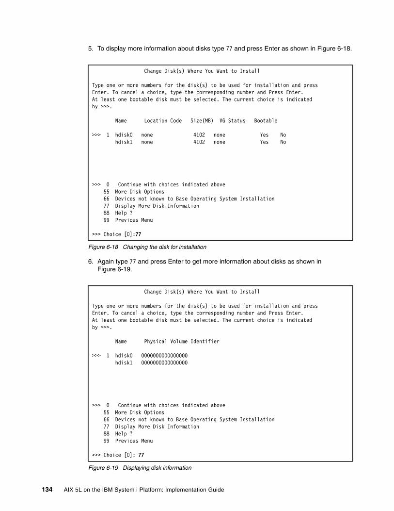
5. To display more information about disks type 77 and press Enter as shown in Figure 6-18.
Figure 6-18 Changing the disk for installation
6. Again type 77 and press Enter to get more information about disks as shown in Figure 6-19.
Figure 6-19 Displaying disk information
Change Disk(s) Where You Want to Install
Type one or more numbers for the disk(s) to be used for installation and pressEnter. To cancel a choice, type the corresponding number and Press Enter.At least one bootable disk must be selected. The current choice is indicatedby >>>.
Name Location Code Size(MB) VG Status Bootable
>>> 1 hdisk0 none 4102 none Yes No hdisk1 none 4102 none Yes No
>>> 0 Continue with choices indicated above 55 More Disk Options 66 Devices not known to Base Operating System Installation 77 Display More Disk Information 88 Help ? 99 Previous Menu
>>> Choice [0]:77
Change Disk(s) Where You Want to Install
Type one or more numbers for the disk(s) to be used for installation and pressEnter. To cancel a choice, type the corresponding number and Press Enter.At least one bootable disk must be selected. The current choice is indicatedby >>>.
Name Physical Volume Identifier
>>> 1 hdisk0 0000000000000000 hdisk1 0000000000000000
>>> 0 Continue with choices indicated above 55 More Disk Options 66 Devices not known to Base Operating System Installation 77 Display More Disk Information 88 Help ? 99 Previous Menu
>>> Choice [0]: 77
134 AIX 5L on the IBM System i Platform: Implementation Guide
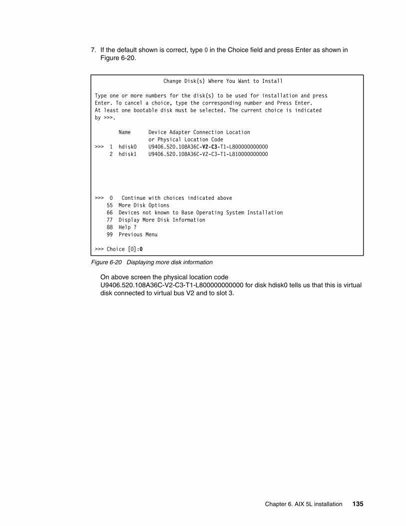
7. If the default shown is correct, type 0 in the Choice field and press Enter as shown in Figure 6-20.
Figure 6-20 Displaying more disk information
On above screen the physical location code U9406.520.108A36C-V2-C3-T1-L800000000000 for disk hdisk0 tells us that this is virtual disk connected to virtual bus V2 and to slot 3.
Change Disk(s) Where You Want to Install
Type one or more numbers for the disk(s) to be used for installation and pressEnter. To cancel a choice, type the corresponding number and Press Enter.At least one bootable disk must be selected. The current choice is indicatedby >>>.
Name Device Adapter Connection Location or Physical Location Code>>> 1 hdisk0 U9406.520.108A36C-V2-C3-T1-L800000000000 2 hdisk1 U9406.520.108A36C-V2-C3-T1-L810000000000
>>> 0 Continue with choices indicated above 55 More Disk Options 66 Devices not known to Base Operating System Installation 77 Display More Disk Information 88 Help ? 99 Previous Menu
>>> Choice [0]:0
Chapter 6. AIX 5L installation 135

8. If you agree with settings on the screen (Figure 6-21), type 0 and press Enter.
Figure 6-21 Installation settings
9. Again approve the settings in Figure 6-22 by typing 1 and pressing Enter.
Figure 6-22 Overwrite Installation Summary
Installation and Settings
Either type 0 and press Enter to install with current settings, or type thenumber of the setting you want to change and press Enter.
1 System Settings: Method of Installation.............New and Complete Overwrite Disk Where You Want to Install.....hdisk0
2 Primary Language Environment Settings (AFTER Install): Cultural Convention................English (United States) Language ..........................English (United States) Keyboard ..........................English (United States) Keyboard Type......................Default
3 More Options (Desktop, Security, Kernel, Software, ...)
>>> 0 Install with the current settings listed above.
+----------------------------------------------------- 88 Help ? | WARNING: Base Operating System Installation will 99 Previous Menu | destroy or impair recovery of ALL data on the | destination disk hdisk0.>>> Choice [0]: 0
Overwrite Installation Summary
Disks: hdisk0Cultural Convention: en_USLanguage: en_USKeyboard: en_US64 Bit Kernel Enabled: YesJFS2 File Systems Created: YesGraphics Software: YesEnable System Backups to install any system: Yes
Optional Software being installed:
>>> 1 Continue with Install +----------------------------------------------------- 88 Help ? | WARNING: Base Operating System Installation will 99 Previous Menu | destroy or impair recovery of ALL data on the | destination disk hdisk0.>>> Choice [1]: 1
136 AIX 5L on the IBM System i Platform: Implementation Guide

Now the installation process of AIX 5L is running as shown in Figure 6-23.
Figure 6-23 Beginning of installation process
10.During installation you are asked to change the volume number of the CD from one to two as shown in Figure 6-24.
Figure 6-24 Requesting to change volume
Installing Base Operating System
Please wait...
Approximate Elapsed time % tasks complete (in minutes)
0 0 Preparing target disks.
. . . . . << Copyright notice for xlC.msg.en_US.cpp >> . . . . . . . Licensed Materials - Property of IBM
5765F5700 (C) Copyright International Business Machines Corp. 1990, 2004.
All rights reserved. US Government Users Restricted Rights - Use, duplication or disclosure restricted by GSA ADP Schedule Contract with IBM Corp.
The following will be added in common to all copyright.map files:
. . . . . << End of copyright notice for xlC.msg.en_US.cpp >>. . . .
Filesets processed: 2 of 58System Installation Time: 12 minutes Tasks Complete: 20%
installp: APPLYING software for: Java14.sdk 1.4.1.6
installp: Please insert volume 2 into device /dev/cd0 and press Enter to continue or enter "q" to quit.
Chapter 6. AIX 5L installation 137
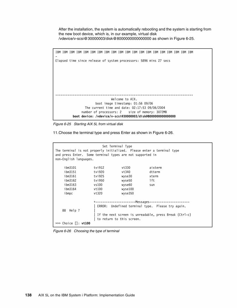
After the installation, the system is automatically rebooting and the system is starting from the new boot device, which is, in our example, virtual disk /vdevice/v-scsi@30000003/disk@8000000000000000 as shown in Figure 6-25.
Figure 6-25 Starting AIX 5L from virtual disk
11.Choose the terminal type and press Enter as shown in Figure 6-26.
Figure 6-26 Choosing the type of terminal
IBM IBM IBM IBM IBM IBM IBM IBM IBM IBM IBM IBM IBM IBM IBM IBM IBM IBM IBM IBM-Elapsed time since release of system processors: 5896 mins 27 secs
------------------------------------------------------------------------------- Welcome to AIX. boot image timestamp: 01:56 09/06 The current time and date: 02:17:53 09/06/2004 number of processors: 2 size of memory: 3072MB boot device: /vdevice/v-scsi@30000003/disk@8000000000000000
Set Terminal TypeThe terminal is not properly initialized. Please enter a terminal typeand press Enter. Some terminal types are not supported innon-English languages.
ibm3101 tvi912 vt330 aixterm ibm3151 tvi920 vt340 dtterm ibm3161 tvi925 wyse30 xterm ibm3162 tvi950 wyse50 lft ibm3163 vs100 wyse60 sun ibm3164 vt100 wyse100 ibmpc vt320 wyse350
+-----------------------Messages----------------------- | ERROR: Undefined terminal type. Please try again. 88 Help ? | | If the next screen is unreadable, press Break (Ctrl-c) | to return to this screen.>>> Choice []: vt100
138 AIX 5L on the IBM System i Platform: Implementation Guide

12.Choose Accept License Agreements as shown in Figure 6-27 and press Enter.
Figure 6-27 Software License Agreement
13.Select yes to ACCEPT Installed License Agreements and press Enter as shown in Figure 6-28.
Figure 6-28 Accept License Agreements
14.Press ESC+0 (or F10 key, it depends on terminal type) to exit the License Agreement menu (Figure 6-29).
Figure 6-29 Accepted License Agreements
Software License Agreements
Move cursor to desired item and press Enter.
Show Installed License Agreements Accept License Agreements
F1=Help F2=Refresh F3=Cancel Esc+8=ImageEsc+9=Shell Esc+0=Exit Enter=Do
Accept License Agreements
Type or select values in entry fields.Press Enter AFTER making all desired changes.
[Entry Fields] ACCEPT Installed License Agreements yes +
F1=Help F2=Refresh F3=Cancel F4=ListEsc+5=Reset Esc+6=Command Esc+7=Edit Esc+8=ImageEsc+9=Shell Esc+0=Exit Enter=Do
COMMAND STATUS
Command: OK stdout: no stderr: no
Before command completion, additional instructions may appear below.
F1=Help F2=Refresh F3=Cancel Esc+6=CommandEsc+8=Image Esc+9=Shell Esc+0=Exit /=Findn=Find Next
Chapter 6. AIX 5L installation 139

15.Exit the Installation Assistant by pressing ESC+0 (or F10) (Figure 6-30). You can set the time, date, password, and others later.
Figure 6-30 Installation Assistant menu
Next the vterm window displays a login prompt as shown in Figure 6-31 and you are asked to login to system. The first time you have to login as root user without password.
Figure 6-31 Console login prompt
At this moment our installation procedure is finished.
For further discussion of the installation process, refer to Chapter 4 of the “AIX Installation in a Partitioned Environment” of AIX 5L Version 5.3: AIX Installation in a Partitioned Environment, SC23-4926, which you can find at:
http://publibfp.boulder.ibm.com/epubs/pdf/c2349260.pdf
6.3 Using bottom slim line CD-ROM/DVD driveThe IBM eServer i5 models 520, 520+, 550 and 550+ support three media bays. Two of the bays are for slimline DVD devices and the other is for a half-height SCSI tape device.
Installation Assistant
Move cursor to desired item and press Enter.
Set Date and Time Set root Password Configure Network Communications Install Software Applications Using SMIT (information only) Tasks Completed - Exit to Login
F1=Help F2=Refresh F3=Cancel Esc+8=ImageEsc+9=Shell Esc+0=Exit Enter=Do
AIX Version 5(C) Copyrights by IBM and by others 1982, 2004.Console login: root******************************************************************************** ** ** Welcome to AIX Version 5.3! ** ** ** Please see the README file in /usr/lpp/bos for information pertinent to ** this release of the AIX Operating System. ** ** ********************************************************************************Last login: Sun Sep 26 12:48:36 CDT 2004 on /dev/vty0
#
140 AIX 5L on the IBM System i Platform: Implementation Guide

The top, or first, media bay has a SCSI-IDE converter that is used to convert the device’s IDE interface to a SCSI interface. The DVD device in this bay will appear as a SCSI device on SCSI bus 0, and is usable to i5/OS partitions. However since it is downstream of a I/O Processor (IOP) adapter, it is not available to any AIX 5L partitions.
The bottom, or second, media bay does not have a SCSI-IDE converter and is connected directly to a IDE bus. Any DVD device using this bay cannot be accessed by an i5/OS partition, instead it will be accessible only to AIX 5L or Linux partitions.
However, when using an HMC at V5R0, or older, HMC would not allow the allocation of the Other mass storage controller to an AIX 5L partition. It would report an error stating that it cannot assign storage device under an I/O Processor to AIX 5L or Linux.
To circumvent this issue, the IOP that controls the slimline media bays would have to be removed, which would disable the DVD drive in the Top bay, or an external DVD drive would have to be used.
Fortunately, this issue was addressed with HMC release V5R1, and newer, allowing the Other mass storage controller to be allocated to AIX 5L or Linux partitions.
6.3.1 Requirements� IBM System i Model 520 or 550 with a DVD drive in the Bottom, or second, media bay
� HMC at V5R1, or newer
6.3.2 ProcessTo allocate this DVD device to an AIX 5L partition, simply select the Other mass storage controller I/O device when allocating physical hardware devices to the partition.
As demonstrated in Figure 6-32 on page 142, the Other Mass Storage Controller device in slot T12 will be allocated to the partition.
Chapter 6. AIX 5L installation 141

Figure 6-32 Other Mass Storage Controller listing
After this is successfully allocated to the AIX 5L partition, the AIX 5L installation process will be the same as 6.2.1, “Physical CD-ROM boot device selection” on page 128.
142 AIX 5L on the IBM System i Platform: Implementation Guide
Related publications
The publications listed in this section are considered particularly suitable for a more detailed discussion of the topics covered in this book.
IBM RedbooksFor information about ordering these publications, see “How to get IBM Redbooks” on page 144. Note that some of the documents referenced here may be available in softcopy only.
� Logical Partitions on System i5: A Guide to Planning and Configuring LPAR with HMC on System i, SG24-8000
� IBM System i5, eServer i5, and iSeries Systems Builder IBM i5/OS Version 5 Release 4 - January 2006, SG24-2155
� Advanced POWER Virtualization on IBM System p5: Introduction and Configuration, SG24-7940
� LPAR Simplification Tools Handbook, SG24-7231
Other publicationsThese publications are also relevant as further information sources:
� IBM eServer i5 and iSeries System Handbook: IBM i5/OS Version 5 Release 3 October 2004, GA19-5486
� AIX 5L Version 5.3 - Installation Guide and Reference, SC23-4887
� AIX 5L Version 5.3 - General Programming Concepts: Writing and Debugging Programs, SC23-4896
� AIX 5L Version 5.3 System Management Concepts: Operating System and Devices, SC23-4908
� AIX 5L Version 5.3 System Management Guide: Operating System and Devices, SC23-4910
� AIX 5L Version 5.3 - AIX Installation in a Partitioned Environment, SC23-4926
Online resourcesThese Web sites and URLs are also relevant as further information sources:
� AIX 5L on eServer i5 home page
http://www.ibm.com/servers/eserver/iseries/aix/index.html
� IBM eServer pSeries and AIX Information Center
http://publib.boulder.ibm.com/infocenter/pseries/index.jsp
� AIX 5L V5.1 and V5.2 Information Center
http://publib16.boulder.ibm.com/pseries/en_US/infocenter/base/aix.htm
© Copyright IBM Corp. 2005. All rights reserved. 143

� AIX 5L V5.3 Information Center
http://publib.boulder.ibm.com/infocenter/pseries/topic/com.ibm.aix.doc/infocenter/base/aix53.htm
How to get IBM RedbooksYou can search for, view, or download Redbooks, Redpapers, Hints and Tips, draft publications and Additional materials, as well as order hardcopy Redbooks or CD-ROMs, at this Web site:
ibm.com/redbooks
Help from IBMIBM Support and downloads
ibm.com/support
IBM Global Services
ibm.com/services
144 AIX 5L on the IBM System i Platform: Implementation Guide

Index
Numerics268C 15, 101
AAddress Translation Wizard 111ADDTCPIFC 106Advanced POWER Virtualization 19ARP 16, 104
Bbay 140boot device 125Boot Mode 127
Ccapped 9CD-ROM device 127converter 141cost of switching 9CRTNWSSTG
i5/OS commandsCRTNWSSTG 17
CUoD 10
Ddatagram forwarding 103dedicated processor 9, 37default partition profile 30default weight 10desired memory 37desired processing unit 38desired value 30direct disk 18Direct Routing 119disk features 18DLPAR 39DMZ 5DNS 108downstream 92, 141duplex 103Dynamic Logical Partitioning 98
EESC+0 140Ethernet Fiber 2-port adapter 92
Ffirst address 104fractions 9frame size 105full system partition profile 30–31
© Copyright IBM Corp. 2005. All rights reserved.
Ggateway 109group of partitions 36group of physical processors 9
Hhalf-height 140hardware error 31hardware error logging 8Hardware Management Console 8Hardware Paging Table 33hardware requirements 21HMC 8hosted 42HPT 33
II/O pool 40I3P 117IDE interface 141identify 100IEEE 802.1Q 53ifconfig 119install/boot device 123INTNETADR 106IOA 18IOP 18IP header 108IPL Source (IPLSRC)
*PANEL 122IPLSRC 122iSeries Navigator 110IXA 2IXS 2
Llast address 104LCLIFC 106LIND 106Local Console Session 8location code 135
Mmaintenance package 122managed system 8mangled 108map address translation 112mapping 107mass storage controller 141maximum memory 37maximum processing unit 38maximum value 30
145

media bay 140memory cache 10memory size 37micro-partitioning 2, 9, 37minimum memory 37minimum processing unit 38minimum value 30mirrored 3MTU 105multiple logical partitions 9
NNAT 16, 93, 107NAT rules 110network address translation 16network connectivity 91Network Installation Manager 121new boot device 138NIC 21NIM 121NWSD 17NWSSTG 17
Ooptimal processor assignment 9overcommitment 30overcommitted resources 31
Ppacket rules 117Packet Rules Editor 110partition ID 30Partition Load Manager (PLM) 19partition profile 30physical LAN 105physical location code 135physical network adapter 115PLM (Partition Load Manager) 19point-to-point 118policy parameter 31predictable performance 10pre-loaded 8private address 107processor feature code 8proxy ARP 16, 93public address 107PWRCTL 122PWRDWNSYS 45
RRAID-5 3rebooting 138re-broadcast 104Redbooks Web site 144
Contact us ixrelative weight 10report error 31restricted state 3, 19
SSCSI interface 141SCSI-IDE 141select boot option 128server error 31Service Focal Point 8service partition 31shared pool 9shared processor 9, 37shared processor pool 9shared processor units 10shutdown 30single physical processor 9slimline DVD device 140SMIT 92SMS 42, 122storage virtualization 3STRTCPIFC 107sub processor feature 37subnet 104subnet mask 92SUBNETMASK 106system model 8system policy parameter 31system profile 31system serial number 8
TT12 141target device 16terminal window 128
Uuncapped 9uncapped logical partition 10USB port 18UTP 2-port adapter 92
Vvalidation 31VIOS (Virtual I/O Server) 19virtual CD 18Virtual Ethernet 3, 15Virtual I/O Server (VIOS) 19virtual LAN 15virtual serial adapter 17virtual storage 14virtual tape 18Virtualization Engine 2VLAN 93VPN 118VRTETH01 103
WWebSM client 8weight 10
146 AIX 5L on the IBM System i Platform: Implementation Guide

(0.2”spine)0.17”<
->0.473”
90<->
249 pages
AIX 5L on the IBM System
i Platform: Im
plementation Guide
AIX 5L on the IBM System
i Platform:
Implem
entation Guide
AIX 5L on the IBM System
i Platform
: Implem
entation Guide
AIX 5L on the IBM System
i Platform: Im
plementation Guide

AIX 5L on the IBM System
i Platform
: Implem
entation Guide
AIX 5L on the IBM System
i Platform
: Implem
entation Guide


®
SG24-6455-01 ISBN 0738486140
INTERNATIONAL TECHNICALSUPPORTORGANIZATION
BUILDING TECHNICAL INFORMATION BASED ON PRACTICAL EXPERIENCE
IBM Redbooks are developed by the IBM International Technical Support Organization. Experts from IBM, Customers and Partners from around the world create timely technical information based on realistic scenarios. Specific recommendations are provided to help you implement IT solutions more effectively in your environment.
For more information:ibm.com/redbooks
AIX 5L on the IBM System i Platform Implementation Guide
Discussion of logical partitions on the IBM POWER5 technology-based System i platform
Description of new devices and products that are supported
Step-by-step installation guide for AIX on the System i platform
On the IBM System i platform, you can run native AIX 5L with its own kernel (versus current the PASE SLIC kernel) in a logical partition (LPAR). This option provides another alternative to consolidate AIX 5L applications and other UNIX-based applications, running in a separate IBM eServer pSeries system or other UNIX system, onto a single System i platform.
With the new version of the AIX 5L V5.3 operating system, the same level of server virtualization, such as dynamic resource allocation, is realized as the current IBM eServer iSeries level server virtualization.
This IBM Redbooks publication discusses various aspects of AIX 5L implementation on IBM System i platforms. It includes the following topics:
� An overview of AIX 5L native support on the System i platform including the benefits of a virtualization engine
� Planning for AIX 5L on the System i platform, with an explanation about new LPAR concepts and tools on the System i platform and initial sizing of an AIX 5L partition
� Installation and configuration of an AIX 5L partition on the System i platform, providing a step-by-step guide for AIX 5L installation, partition setup, and maintenance that includes a scenario of virtual I/O and direct I/O
This book helps system administrators to install, tailor, and configure an AIX 5L partition on the System i platform.
Back cover