aisi example ii-7
DESCRIPTION
Aisi example II-7TRANSCRIPT

11-168 Beam Design for Use with the 2007 North American Cold-Formed Steel Soe
Example 11-7: Tubular Section - Round
Given:
1. Steel: Fy = 42 ksi
2. Section: Shown in sketch above
Required:
. 1. Determine the ASD allowable flexural strength, M; /ºb .2. Determine the LRFD design flexural strength, $bMn .
Solution:
1. Nominal Flexural Strength (Section C3.1.3):
Ratio of outside diameter to wall thickness,D/t = 8.0010.100 = 80.0
Check limitD/t < 0.441E/Fy = 0.441(29500/42) = 310 OK
Full Section Properties_ [Outsíde Diameter t -[Inside Diameter t
Sf -n~------~--~~----~----~32 (Outside Diameter)
(8.00t -(7.80t= n -'---~.,.....,.-'---:~(32)(8.00)
=4.84 in."Determine the governing equation
0.0714E/Fy =0.0714(29500/42)=50.2
0.318E/Fy = 0.318(29500/42) = 223
Since 0.0714E/Fy < D/t < 0.318E/Fy
F, = [0970 + 0.D20(~;: ) ]Fy
Fe = [0.970 + 0.020( 29~~~b42)]42 = 48.1 ksi

= ign for Use with the 2007 North American Cold-Formed Steel Specification 11-169
- in = FeSE
= (48.1)(4.84) = 233 kip-in.
(Eq. C3.1.3-1)
allowable flexural strength
- in _ 233 -140 ki .----- p-m.o, 1.67
deslgn flexural strength
M, = (0.95)(233) = 221kip-in.

11-170 Beam Design for Use with the 2007 North American Cold-Formed Steel
Example 11-8: Tubular Section - Rectangular
ytI
1\ 'R = 0.0494 inl
I6.00 in.] -If------l------
I,-1t- t = 0.125 in. !
I
Given:
f-- ----+x
1. Steel: Fy = 46 ksi
2. Section: HSS 6x6x1fs(from Table 1-12, AISC Steel Construction Manual, 2005)
3. Calculated gross properties using nominal dimensions aboveA = 2.91 in.21 = 16.7 in.sS = 5.56 in.3
3. Simple span length = 10.0 ft
4. Laterally braced at both ends
Required:
1. Determine the ASD flexural allowable strength, Mn/nb .
2. Determine the LRFD design flexural strength, cj>bMn .
3. Compare the calculated available flexural strengths to those calculated using the AIScedures. The inside radius given above is selected to give the same flat width, w, f,flanges and webs used in the AISC calculations.
Solution:
~: I :1I 6.00 in.
Compute the nominal flexural strength, Mnt according to Specification Sections C3.1.1(a) ~-C3.1.2.2 for closed box members.
1. Nominal Flexural Strength, Mn,based on initiation of yielding (Section C3.1.1):
Check the compression flange as a uniformly compressed compression element in adance with Section B2.1. By calculations not shown, the effective width of the compressiarflange width is found to be 4.608 in.
Check webs in accordance with Section B2.3. The webs are found to be fully effective.Ecalculations not shown.
The effective section properties can then be calculated as:
I, = 15.5 in.s

:: "or Use with the 2007 North American Cold-Formed Steel Specification 11-171
••• "••• ~__ o....",1 flexural strength is calculated as:
"Fy= =95)(46) = 228kip-in. or 19.0 kip-ft
(Eq. C3.1.1-1)
".Ia.1 Flexural Strength, Mn, based on lateral-torsional buckling (Section C3.1.2.2):
"''''-'--="''" _ Specification Eq. C3.1.2.2-1,the minimum unbraced length of a closed box memberateral-torsional buck1ing, Lw is calculated as:
_ = 0.36Cb7t ~EGJly (Eq. C3.1.2.2-1)FySf
- = 1.0 (assumed):Ullsection) = 16.7 ín.s
nill section) = 5.56 in."
2( ab)2(Eq. C-C3.1.2.2-1)
- ea=b=D-t=6.00-0.125=5.875 in.tI = t2 = 0.125 in.
2(5.875)4 . 4)
= 25.3m.(5.875/0.125
(Eq. C-C3.1.2.2-1)
= ~.3~¡1.0)) J(29500)(11300)(25.3)(16.7) = 1660 in. = 138 ft- 46 5.56
(Eq. C3.1.2.2-1)
> ..,0.0 ft, the member is not subject to lateral-torsional buckling and the flexural~ oased on Section C3.1.1(a). That is,- = 19.0 kip-ft
owable flexural strength
~ - 19.0 -11 4 k' f----- . lp- t1.67
deslgn flexural strength
_.~ = (0.95)(19.0) = 18.1kip-ft.
c:::.mparisonof AISI and AISC available flexural strengths
- available flexural strengths calculated above are compared with those calculated in- ordance with the 2005 AISC Specification in the table below. AISC strengths are- cenfrom Table 3-13 of the 13th Edition of the AISC Steel Construction Manual.

11-172 Beam Design for Use with the 2007 North American Cold-Formed Steel
Available AISI AISCI
AISI--
Strength kip-ft kip-ft AISC
ASD: Mn/nb 11.4 10.8 1.06
LRFD: <PbMn 18.1 16.2 1.12
-The differences between the AISI and AISC strengths shown in the table above are dfollowing factors:
a. The AISI calculations were performed using the nominal wall thickness of the HS5the AISC calculations were performed using 93% of the nominal wall thickness as :2.-.--........by AISC.
b. The calculations of the effective width of the compression flange are slightly diff~~two specifications, including slightly different values of E.
c. For the LRFD method, the resistance factor used in the AISI Specification is <Pb = O_~the resistance factor used in the AISC Specification is <Pb = 0.90.
d. The differences shown in the table above are representative of HSS sections ha" .elements, but actual ratios vary somewhat based on section dimensions and yield _
~-
.~

tor Use with the 2007 North American CoJd-Formed SteeJ Specification ))-173
C-Section with Openings
~625 in. I::;::::::::::=:::::::)j 10.500 in.
: 0.1070in.
<i.I ., PD: 0.150kips
PL: 0.750kips1.5x 4.5 in.punchouts
5 in.
= 0.0713in.
3i~n.~~~======~====================~========~==~
t 12 in. I 24 in. I 12 in. '0• ---.--. --48i-n. --.~_.--:!
Fy = 50 ksi, Fu = 65 ksi
'E~n;' 400S162-68 as shown above
-3e:±:..:'n is simply supported, fully braced against lateral-torsional and distortional buckling,.s fastened to support.
y 4.5 in. web punchouts with 0.25 inch comer radii located as shown above. Note_ e location of punchouts is often not known with this precision.
- adequacy of the section considering:-='exureShear
.7eb CripplingCombined Bending and ShearCombined Bending and Web Crippling
_. D - ASCE/SEI 7-05 ASD load combination D + L:RFD - ASCE/SEI 7-05 LRFD load combination l.2D + 1.6L
_ ect self weight of beam
_ - ed Strength
•nired Strength= PD+ PL= 0.150 + 0.750 = 0.900 kips
- = P/2 = 0.900/2 = 0.450 kips

11-174 Beam Design for Use with the 2007 North American Cold-Formed Stee' ~
At center, away from holes
PL (0.900)(8.0)M = 4 = A = 1.80 kip-ft = 21.6 kip-in.
At edge of hole closest to center
M = V[L/2 -(12.0 - 2.25)J = (0.450)[96.0/2 - 9.75] = 17.2 kip-in.
LRFD Required StrengthP, = 1.2PD + 1.6PL = (1.2)(0.150)+ (1.6)(0.750) = 1.38kips
Vu = P¿ /2 = 1.38/2 = 0.690 kips
At center, away from holes
P L (1.38)(8.0)M, = _u_ = = 2.76 kip-ft = 33.1 kip-in.4 4
At edge of hole closest to center
M, = Vu [L/2 - (12.0 - 2.25)J = (0.690)[(96.0/2) -9.75] = 26.4kip-in.
b) Flexural Strength without Holes
The member is not subject to lateral-torsional buckling, so compute strength usinz ~~"Ir
C3.1.1 with effective section modulus, Se,at f = Fy.
It can be shown that, in the area without holes, the section is eligible for strength in.. ~using the cold work of forming provisions of Section A7.2.
Fy = Fya= 56.6 ksi (calculations not shown)Se = 0.670 in.' (calculations not shown)M, = SeFy
= (0.670)(56.6) = 37.9kip-in.
e) Nominal Flexural Strength with Holes
The member is not subject to lateral-torsional buckling, so compute strength usingC3.1.1 with effective section modulus, Se,at f = Fy.
Check web using Section B2.4 - "C-Section Webs with Holes under Stress Gradient".dh = 1.5 in.Lh = 4.5 in.
h = 4.00 - 2(0.1070 + 0.0713) = 3.643 in.
Check limitsdh/h = 1.5/3.643 = 0.412 < 0.7 OK
h/ t = 3.643/0.0713 = 51.1 < 200 OK
Holes are centered at mid-depth of web OKClear distance between holes = 24.0 - 4.5 = 19.5 in. > 18.0 in. OK
Comer radii = 0.25 in. > (2)(0.0713) = 0.143 in. OK
di, < 2.5 in. OKLi, = 4.5 in. OK

_ ígn for Use with the 2007 North American Cold-Formed Steel Specification 11-175
h> 9/16 in. OK
.::rxe dh/h > 0.38, treat compression portion of web as a uniform1y compressed unstiffenedent as follows:
: = (h-dh)/2=(3.643-1.50)/2=1.072in.
= 0.43
- ate first estímate of ÍI at the top of the flat width using similar triangles with grosses.
- f - 50(4.00/2-0.0713-0.1070) k .- 1 - = 45.5 SI4.00/2
- 71?E ( t J2v zr = k 12(1-¡.t2) W
= 0.43 rc2
(29500) (0.0713J2 = 50.7ksi12(1-0.32) 1.072
=)t= ~45.5 = 0.947> 0.673 .'. web is subject to local buckling
50.7
= (1-0.22/A)/A
= (1- 0.22/0.947)/0.947 = 0.811
(Eq. B2.1-5)
(Eq. B2.1-4)
(Eq. B2.1-3)
=pw
= (0.811)(1.072) = 0.869 in.(Eq. B2.1-2)
- - e web is not fully effective, the cross section is not eligible for design using the coldt: íorming provision in this area.
- ange and Lip
hown that the flange and lip are fully effective at this stress level (calculations not
-,,--.---_"'te Section Properties
_ •...__ u_ the effectíve sectíon modulus, Se, deducting both the 1.50 inch hole and the inef-"::'rtion of the compression area of the web. Using the methods illustrated in the ex-~ Part 1,the effectíve flexural properties can be computed as:
= _03 in. (from top fiber)= :.32 in.'= .648 in.>
-' the centroid causes a very slight change to the stress distribution and conse-'ery small change in the value of ÍI at the top of the flat width of the web, but not
_c:::::: - change the values calculated above.

11-176 Beam Design for Use with the 2007 North American Cold-Formed Stee
Nominal Flexural StrengthMn =SeFy
= (0.648)(50) = 32.4 kip-in.
Alternatively, M, can be taken from Table II-2. For a 400S162-68 with Fy= 50M, = 32.4 kip-in.
d) Available Strength
ASD Allowable Strengtho, =1.67
At center, away from holes
Mn = 37.9 = 22.7 kip-in. > 21.6 kip-in. OKo, 1.67
At holes nearest center
Mn = 32.4 = 19.4 kip-in, > 17.2 kip-in. OKo, 1.67
LRFD Design Strength</>b =0.95
At center, away from holes</>bMn = (0.95)(37.9) = 36.0 kip-in. > 33.1 kip-in. OK
At holes nearest center</>bMn = (0.95)(32.4) = 30.8 kip-in. > 26.4 kíp-in. OK
2. Shear Strength
a) Required Strength
ASD Required StrengthV = 0.450 kips (from above)
LRFD Required StrengthV, = 0.690 kips (from above)
b) Shear Strength without Holes - Section C3.2.1hit = 51.1 (computed above)
~Ekv/Fy = ~(29500)(5.34)/50 = 56.1
Since hit < ~Ekv/Fy ,
Fv = 0.60Fy
= (0.60)(50)=30 ksi
Vn = AwFv
= (3.643)(0.0713)(30) = 7.79 kips
c) Shear Strength with Holes - Section C3.2.2
Limits same as those checked above OK

:- ign for Use with the 2007 North American Cold-Formed Steel Specification 11-177
= h/2-dh/2
= 3.643/2 -1.50/2 = 1.07 in.
e] t = 1.07/0.0713 = 15.0
.5< c/t < 54,
s = cj(54t)
= 1.07/[(54)(0.0713)J = 0.278
'n = qsVn = (0.278)(7.79) = 2.17 kips
(Eq. C3.2.2-3)
(Eq. C3.2.2-1)
- :ematively, Vn can be taken from Table Il-2. For a 4005162-68 with Fy = 50 ksi,··-n = 2.17 kips
- . able 5trength
- owable 5trength=1.60
- = 2.17 = 1.36 kips > 0.450 kips. OK1.60
.gn 5trength=0.95
= (0.95)(2.17) = 2.06 kips > 0.690 kips. OK
ined Bending and Shear Strength
- .,..the center of the beam (no holes)
(Eq. C3.3.1-1)
=-- )(21.6)J2 [(1.60)(0.450)J2
+ = 0.956 < 1.0 OK37.9 7.79
ge of the hole closest to the center
- r )(17.2)J2
[(1.60)(0.450)J2
+ = 0.947 < 1.0 OK32.4 2.17
(Eq. C3.3.1-1)
atively, this case can be checked with Table Il-l1a. For a 4005162-68 with Fy = 50 ksi,a required allowable moment, M, of 17.2 kip-in., conservatively interpolate the maxi-permitted shear, V.
~ T M = 16.8 kip-in., V s 0.678 kips:\1 = 18.7 kip-in., V s 0.351 kips
- T M = 17.2 kip-in., interpolating,
V s 0.351+(18.7 -17.2)(0.678_0.351) = 0.609 kips > 0.450 kips OK~18.7 -16.8

11-178 Beam Design for Use with the 2007 North American Cold-Formed Steel Sp""''''='--
LRFD
Near the center of the beam (no holes)
Ir M J2 ( V J2+ -- <10~bMnxo ~v Vn _.
M =M,
V -v;
[ )
233.1 + 0.690 2_
(0.95)(37.9) [(0.95)(7.79)) - 0.924< 1.0 OK
At edge of hole closest to the center
[ )
2 [26.4 0.690 2
(0.95)(32.4) + (0.95)(2.17)) = 0.921< 1.0 OK
Alternatively, this case can be checked with Table I1-11b. Por a 400S162-68 with Fy =using a required moment, M¿ of 26.4 kip-in., conservatively interpolate the maximum -mitted factored shear, Vu.
for M, = 21.8 kip-in., Vu~ 1.46 kipsfor M, = 26.7 kip-in., Vu ~ 1.03 kipsfor M, = 26.4 kip-in., interpolating,
v: ~1.03+(26.7 -26.4)(1.46_1.03) = 1.06 kips > 0.690 kips OK26.7 -21.8
4. Web CripplingStrength
a) Required Strength
ASD Required Strength
End ConditionP = V = 0.450 kips
Interior ConditionP = Po + PL= 0.150 + 0.750 = 0.900 kips
LRFD Required Strength
End ConditionPu = Vu = 0.690 kips
Interior Condition
Pu = 1.2Po + 1.6PL= (1.2)(0.150) + (1.6)(0.750) = 1.38kips
b) Web Crippling Strength without Holes - Section C3.4.1e = 90 degreesR = 0.1070 in.t = 0.0713 in.

__esign for Use with the 2007 North American Cold-Formed Steel Specification 11-179
= 3.643 in.
- - Condition_- = 3.0 in.
Table C3.4.1-2
- limits_/t = 51.1 < 200 OK (computed above)_-/t = 3.0/0.0713 = 42.1 < 210 OK
_-/h = 3.0/3.643 = 0.823 < 2.0 OK
onditions of Fastened to SupportjStiffened or Partially Stiffened FlangesjOne Flange.....•...=LU·LL',gjEndCondition:
Lo =4R = 0.14. = 0.35
= 0.02= 1.75= 0.85
~ t = 0.1070/0.0713 = 1.50 < 9 OK
~Ct2Fysme[1- e,~)[ 1+eN~)[ 1- e, Jf)= 4)(0.0713)2 (50)Sin(90)[I- 0.14 0.1070 )[1 + 0.35 ¡3.())[1-0.02
0.0713 ~o.om=_36 kips
-_-=:...LLatively,Pn can be conservatively interpolated from Table I1-14. For a 400S162-68 with- ksi, fastened to support, case A:
= 2 in., P, = 2.06 kips= 4 in., Pn = 2.61 kips
~ = 3 in., interpolating, Pn = 0.5(2.06 + 2.61) = 2.34 kips
(Eq. C3.4.1-1)
3.643 )0.0713
íor Condition_- = 5.0 in.
Table C3.4.1-2
limits (other limits checked above)_- t = 5.0/0.0713 = 70.1 < 210 OK
- h = 5.0/3.643 = 1.37 < 2.0 OK
ditions of Fastened to SupportjStiffened or Partially Stiffened FlangesjOne Flange___- -..••,gj Interior Condition
- =13--,. = 0.23

Interior Conditionx = 12.0 - 4.50/2 - 5.0/2 = 7.25 in. (distance between web hole and edge of bearinz
Re = 0.90 - 0.047dh/h + 0.053x/h:-:;1.0'
= 0.90 - (0.047)(1.50)/3.643 + (0.053)(7.25)/3.643 = 0.986 < 1.0 OK
Pn = RePn =(0.986)(4.79) =4.72 kips
Alternatively, Recan be conservatively interpolated from Table II-16a. For depth = 4 .for x = 4 in., Re= 0.94for x = 8 in., Re= 0.99
for x = 7.25 in., interpolating, Re= 0.94+(7.25-4)(0.99-0.94) = 0.988-4
11-180 Beam Designfor Usewith the 2007 North American Cold-FormedSteel __
CN = 0.14Ch = 0.01nw = 1.65<pw = 0.90R/t = 1.50 < 5.0 OK
r, ~Ct2Fysine ( l-CR~J( l+CNf¡IJ( l-Ch~J= (13)(0.0713)2 (50)Sin(90)(1- 0.23 0.1070 J(l+ 0.14 [5JJJ(l- 0.01 3.643
0.0713 VM713 0.0713
=4.79 kips
Alternatively, Pn can be conservatively interpolated from Table II-14. For a 400S16::-Fy = 50 ksi, fastened to support, case B:
for N = 4 in., Pn = 4.51 kipsfor N= 6 in., Pn = 5.03 kipsfor N= 5 in., interpolating, Pn = 0.5( 4.51 + 5.03) = 4.77 kips
e) Web Crippling Strength with Holes - Section C3.4.2
Limits same as those checked above OK
End Conditionx = 12.0 - 4.50/2 - 3.0/2 = 8.25 in. (distance between web hole and edge of bearír
Re = 1.01- 0.325dh /h + 0.083x/h :-:;1.0
= 1.01-(0.325)(1.50)/3.643 + (0.083)(8.25)/3.643 = 1.06> 1 Use 1.0
P, = RePn = (1.0)(2.36) = 2.36 kips
Alternatively, Recan be extrapolated from Table II-16b. For stud depth = 4 in., x » 5Re = 1.00
-z tor Use with the 2007 North American Cold-Formed Steel Specification 11-181
- ble Strength
T .able Strength- Condition
= 1.75
- = 2.36 = 1.35 kips > 0.450kips OK1.75
- ior Condition__ = 1.65
- = 4.72 = 2.86 kips > 0.900kips OK1.65
=0.85Po = (0.85)(2.36) = 2.01kips > 0.690kips OK
-or Condition=0.90
P; = (0.90)(4.72) = 4.25kips> 1.38kips OK
ined Bending and Web Crippling
1""' ---::rated load at center of beam controls-SI)
0.91(R.) + (~) ~ 1.33r; Mnxo o
0.91(0.900)+(21.6)~ 1.334.72 37.9 1.70
0.743< 0.782 OK~
0.91( P )+( M )~1.33<l>Pn Mnxo
(Eq. C3.5.1-1)
(Eq. C3.5.2-1)
P =P,
=M,
0.91(1.38) + (33.1) s 1.33(0.90)4.72 37.9
1.14 < 1.20 OK
11-182 Beam Design for Use with the 2007 North American Cold-Formed Stee
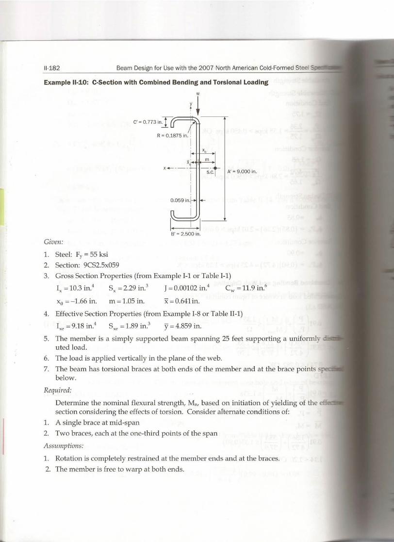
Example 11-10: C-Section with Combined Bending and Torsional Loading
1. Steel: F, = 55 ksi2. Section: 9CS2.5x0593. Gross Section Properties (from Example 1-1or Table 1-1)
I,= 10.3 in." Sx = 2.29 in.' J = 0.00102in." Cw = 11.9 in."
xo = -1.66 in. m = 1.05 in. x = 0.641in.
4. Effective Section Properties (from Example 1-8or Table I1-1)
Ixe= 9.18 in." Sxe= 1.89 in? y = 4.859 in.
5. The member is a simply supported beam spanning 25 feet supporting a uniformly -uted loado
6. The load is applied vertically in the plane of the web.7. The beam has torsional braces at both ends of the member and at the brace points s;
below.
Required:
Determine the nominal flexural strength, Mn, based on initiation of yielding of thesection considering the effects of torsion. Consider alternate conditions of:
1. A single brace at mid-span2. Two braces, each at the one-third points of the span
Assumptions:
1. Rotation is completely restrained at the member ends and at the braces.2. The member is free to warp at both ends.
w
l¡--....¡
. 1
B' = 2.500 in.
Given:
m
S.C.I I A' = 9.000 in.

tion:
Design for Use with the 2007 North American Cold-Formed Steel Specification 11-183
A torsional reduction factor, R is calculated using Section C3.6 and applied to the nominalstrength calculated using Section C3.1.1(a). Note that this reduction factor is not applied toother limit states, such as lateral-torsional buckling or distortional buckling.
This solution is based on the method described in the AISC Steel Design Guide Series 9:"Torsional Analysis of Structural Steel Members"7 (DG 9). The actualloading is modeledy superimposing the three conditions as shown in the figure below.
w t,
_ along Load through Distributed Brace at Brace ateb shear center torque mid-span 1/3 points
Simple DG 9 Case 4 DG 9 Case 3 DG 9 Case 3bending t,=wxo u= 0.5 u = 0.33 and 0.67
Ti T2 = T2
Loading = #1 #2 #3 #3A
Torsional warping stresses are calculated using the second derivative of the angle of rota-ion, 8, with respect to the posítion, 2, along the length oEthe member.
The sign convention for use with all torsionressions are shown in the figure to the
rizht. Note that calculated values for 8 andmay be either positive or negative. The
::-Topersign for these calculated values must_ used for torsional stress calculations. Cal-:ulated positive values are in the directions: own.
••";~
, ,, ,, ,
Compression/¡-,
PointA
Point Brc---:>~,:--ro _.~ Z-<lirection
Positive rotation and warping stresses
~ P.A and Carter, Cl, "Torsional Analysis of Structural Steel Members - Steel Design Guide Se-- ,American Institute of Steel Construction, Chicago, IL, 1997

11-184 Beam Design for Use with the 2007 North American Cold-Formed ,,-=..
For the singly-syrnmetric channel, only the compression side need be checked for f"" c;' d~bending and warping.
Normal Stresses Due to Warping~s = EWns8" (AISCDesign G·_--
where Wns are normalized warping functions (section properties) of the cross-seczx __ ;each point of consideration given by:
Point A, at tip of flange stiffener
WA
= a(n:-b) -c(m+b)
Point B, at junction of the flange and stiffener
a(m-b)WB
= ---'-_--.é..2
Point C, at junction of the flange and web
W. _ amc- 2
where,a = centerline web height = 8.941 in.
b = centerline flange width = 2.441 in.e = centerline lip length = 0.744in.m = distance from shear center to web centerline = 1.05 in.
The torsional warping properties for this section are:
WA
= (8.941)(1.05-2.441) -(0.744)(1.05+2.441)=-8.82in.22
(8.941)(1.05 - 2.441)WB = = -6.22 in.?
2(8.941)(1.05)
Wc = =4.69 in.?2
Formulas for rotation due to a number of torsionalloadings are given in Appendix C.4o:_Surnmarized below are those used in subsequent ca1culations.
For Loading #2 above, use DG 9 Case 4 - Uniformly distributed torque on member with _- WIIII
ends.
tra2
[ L2
(z Z2J (z) (L). (z) 18t =- - --- +cosh - -tanh - sinh - -1.0Q ~2 L ~ a ~ a
where
JECwa= GJ
Differentiating twice with respect to z yields

:o Design for Use with the 2007 North American Cold-Formed Steel Specification 11-185
Loadings #3 and #3A above, use DG 9 Case 3 - Concentrated torque at aL.
for o s z:S;aL
and
e~=~[[Sinh(~) -COSh(aLJlSinh(~JIaGJ tanh(~ J a a
_ ote that the reduction factor, R, defined in Eq. C3.6-1,is a ratio of calculated stresses.These calculated stresses are directly proportional to the value of the applied uniform loadoThus a load of any magnitude can be used to calculate R. In this example, a load of w = 10pounds/foot is used.
Mid-Span Bracing .
mid-span bracing, the stresses are maximum at mid-span. Combine Loadings #1, #2 and
_ ••...•.•...,g #1 - Simple bending through the shear center
f _Myb - I
M = _wL_2= 10(25/ (12) = 9.38kip-in.
8 8(1000)
tresses at top flange points A, B and C are all compression stresses.
_ 9.38(4.859-0.773) _ k .fbA - - - -4.18 SI
9.189.38(4.859) .
fbB= fbC= - = -4.97ksl9.18
___iU.LL,g#2 - Uniformly distributed torque - use DG 9 Case 4.
tra2
[L2(Z Z2) (zJ (LJ' (zJ 1et
=-- -- --- +cosh - -tanh - sính - -1.0GJ 2a2 L L2 a 2a a
-.rhere
10(1.05) . . .tr = ( ) = 0.000875kíp-ín.Zin.
12 1000
a = 29500(11.9) = 175 in.11300(0.00102)

11-186 Beam Design for Use with the 2007 North American Cold-Formed Steel
L= 25(12) = 300 in. L/a =300/175 =1.71
z = 150 in. z/L = 150/300 = 0.500 z/a = 150/175 = 0.857
(1.71)2( 2)0.000875(175)2 0.500-(0.500) +cosh(0.857)e = '---'-:-1 2
t 11300(0.00102) _tanh(_L~_l)sinh(0.857) -1.0
= 0.199radians
e" = 0.000875 [-1.0 + cosh(0.857) - tanh(1.71)Sinh(0.857)]t 11300(0.00102) 2
= 21.2 X 10⁻⁶
Loading #3 - Brace at Mid-Span - use DG 9 Case 3 with a = 0.5.
for O~z~aL
r ['nhaL J 1SI -TL z a a aL. zeT =- (1.0-a)-+- -cosh- sính >
GJ L L tanh L a aa
and
r[inh
aL J 1N T s -eT=_ a aL zaGJ L - cosh- sinh-
tanh- a aa
Set T = 1.0 to find the rotation per kip-in.
_ 1.0(300) [ 1 (Sinh( 0.5(1.71)) ) .eT - ( ) (1-0.5)0.5+- () -cosh(0.5(l.71)) sinh
11300 0.00102 1.71 tanh 1.71
= 1.21 radians
ei = 1.0 [(Sinh(0.5(1.71)) ) 1175(11300)(0.00102) tanh (1.71) - cosh (0.5(1.71)) sinh (0.857)
= -172 X 10-6
Calculate the required value of torque provided by míd-span brace to prevent rotation aspan.
e = et+TIeT=0.199+TI(1.21)=0
TI = -0.164kip-in.
Using this brace force, combine the calculated values for e" from each loading to obtain e'the mid-span braced condition.
eN = e; + T1ei = -21.2x10⁻⁶ -0.164( -172x10-6) = 7.01x10⁻⁶
The torsional warping stresses are:
~ = EWne"= 29500Wn(7.01x10⁻⁶) = 0.207Wn

~ Design for Use with the 2007 North American Cold-Formed Steel Specification 11-187
f.vA= 0.207 (-8.82) = -1.83 ksi
f.vB= 0.207 (-6.22) = -1.29 ksi
f.vc = 0.207( 4.69) = 0.971 ksi
:e::a:rrti'TI1ethe location of the maximum combined flexural and warping stress.
fA = fbA+ f.vA= -4.18 -1.83 = -6.01 ksi
fB= fbB+.f.vB= -4.97 - 1.29 = -6.26 ksi CONTROLS
fe = fbe + f.vc = -4.97 + 0.971 = -4.00 ksi
ate the reduction factor.
fbendingR (Eq. C3.6-1)
fbendmg+ ~orsion
-4.97 = 0.794-4.97 -1.29
_.ote that this value occurs at the intersection of the flange and stiffener; therefore, no in-ease is permitted.
nlate the nominal yielding strength.
M, = RSeFy
= (0.794)(1.89)(55) = 82.5 kip-in.
applicable lirnit states should also be evaluated (not shown) .
. d-Point Bracing
=-. condition, stresses are calculated at both the third-points and at mid-span, since it is not~-:"'"11.1Sby inspection which location will govem. Superimpose the stresses from Loadings #1,
#3A. Use DG 9 Case 3 to calculate e and 9" at these points due to the torsional restraint-=-"_'1'ied by the braces. The value of the torque at the brace points is calculated by requiring
:. e value of e be zero at these two points. Note by syrnrnetry, the torques at the braces are
-":;"'-~l.g #1 - Simple bending through the shear center
:?:exural stresses mid-span are the sarne as previously calculated. Those at the third-pointsare:
_ wL2 _ 10(25)212 _ ..M - -9-- 9(1000) -8.33 kip-in,
4A = - 8.33 (4.859 - 0.773) = -3.71 ksi9.18
4B = fbC= - 8.33 (4.859) = -4.41 ksi9.18
- o- #2 - Uniformly Distributed Torque - Use DG 9 Case 4
--a!ues at mid-span are as previously calculated. Those at third-points are:
z = L/3 = 100in. z/L = 0.333 z/a = 0.571

11-188 Beam Design for Use with the 2007 North American Cold-Formed Steel S--
8t1/3
(1.71)2( 2)= 0.000875(175)2 2 0.333-(0.333) +cosh(0.571)
11300(0.00102) (1.71)-tanh 2 xsinh(0.571)-1.0
= 0.173rads
By syrnmetry, rotation at the 2/3 point is equal to the rotation at the 1/3 point: 8u,= =
8" = 0.000S75 [-1.0 + cosh(0.571) - tanh( 1.71) sinh (0.571)]u/s 11300(0.00102) 2
= -19.0 X 10-Q
By symmetry, 8" at the 2/3 point is equal to 8"at the 1/3 point: 8;2/3= 8;1/3
Loading #3A - Braces at third-points - Use DG 9 Case 3 with ex = 0.667
Apply the brace torque at 2/3 point and calculate 8T and 8~ at z = L/3, z = L/2 anc -::.2L/3.
For z = L/3 = 100 and ex = 0.667
[ [
Sinh(0.667(1.71)) J1.0 300 1
8T1/3= /)) (1-0.667)0.333+- tanh(l.71) sinh(0.571)11300 0.00102 1.71 ( )
-cosh 0.667(1.71)
= 0.S26radians
8" = 1.0 [(Sinh(0.667(1.71)) JTl/3 175(11300)(0.00102) tanh (1.71) - cosht 0.667(1.71)) sinh( 0.571
= -67.1 X 10-Q
For z = L/2 = 150
8 = 1.0(300) [ 1 [Sinh(0.667(1.71)) JTl/2 11300(0.00102) (1-0.667)0.500+ 1.71 tanh(1.71) Sinh(0.S57)J
=coshf 0.667(1.71))
= 1.03 radians
8" - 1.0 [(Sinh(0.667(171)) J-Tl/2 - 175(11300)(0.00102) tanh(l.71·) cosh(0.667(1.71)) sinh(0.S57)
= -lOS X 10-6
For z = 2L/3 = 200
8 = 1.0(300) [ 1 [Sinh(0.667(1.71)) J 1T2/3 11300(0.00102) (1-0.667)0.667 + 1.71 tanh(l.71) sinh(1.14)
-cosh( 0.667(1.71))
= 0.982radians

:: tgn for Use wíth the 2007 North American Cold-Formed Steel Specification 11-189
"- 1.0 [[Sinh(0.667(1.71)) J . 1BT2/3- ( )( ) () -cosh(0.667(1.71)) slnh(1.14)175 11300 0.00102 tanh 1.71
....-.----.:::te the value of the torques at third-points required to prevent rotation at those brace
= -156 X 10-6
1/3 = 9tl/3 + T2BTl/3 + T29T2/3= 0.173 + 0.826T2+ 0.982T2 = O
= -0.0957 kip-in.
______ = ~ torsional warping stresses at the 1/3 and 2/3 points.
= -19.0xl0-6 + (-0.0957)( -67.1xl0-6) + (-0.0957)( -156xl0-6)
= 2.35xl0-6
= 29500Wn (2.35xl0-6) = 0.0693Wn
= 0.0693( -8.82) = -0.611ksi
- - = 0.0693(-6.22) = -0.431 ksi
- = 0.0693(4.69) = 0.325 ksi
e location of the maximum combined flexural and warping stress.-_ =Í¡,A+lA =-3.71-0.611=-4.32ksi
= Í¡,B+ lB = -4.41- 0.431 = -4.84 ksi CONTROLS
:: = 4c+ le = -4.41 + 0.325 = -4.09 ksi
~-=:.. e reduction factor at the 1/3 and 2/3 points.
-4.41 = 0.911-4.41- 0.431
nominal yielding strength at the 1/3 and 2/3 points.
(Eq. C3.6-1)
= 0.911)(1.89)(55) = 94.7kip-in.
ional warping stresses at mid-span.
_ = 9;1/2+ 2T29i1/2 = -21.2x10⁻⁶ + 2( -0.0957)( -108xl0-6)
= -0.529 X 10⁻⁶
500Wn (-O.529x10-6) = -0.0156Wn
=-0.0156 (-8.82) = 0.138 ksi
.0156(-6.22) = 0.0970 ksi

11-190 Beam Design for Use with the 2007 North American Cold-Formed Stee. 5::.....-
~e = -0.0156 (4.69) = -0.0732 ksi
Determine the location of the maximum combined flexural and warping stress.fA=fbA+~A =-4.18+0.138=-4.04ksi
fB= fbB+ ~B = -4.97 + 0.0970= -4.87 ksi
fe = fbe+~e = -4.97 - 0.0732= -5.04 ksi CONTROLS
Calculate the reduction factor at mid-span.
R = (1.15) -4.97 = 1.13 > 1.0-4.97 -0.0732
Since R exceeds 1.0, take R as 1.0 at midspan. The 15%increase is permitted since the .LL""-~
combined stress occurs at the junction of the flange and web.
Calculate the nominal yielding strength at mid-span.Mn = RSeFy
= (1.0)(1.89)(55) = 104kip-in.

sign for Use with the 2007 North American Cold-Formed Steel Specification 11-191
le 11-11: Web Crippling
3.0 in.O--+ll-f-
3.0 in.O-+~-f- 12.0 in.
3.0 in.O-+ll-f-
3.0 in.
v//////4.0 in.
- exural member: SSMA Stud 1200S200-68(50ksi)
--,aring stiffener: SSMA Stud 362S162-33(33ksi)
_ ed:
Calculate the available bearing strength of the joist section with the C-section bearing stiff-er using both ASD and LRFD
um:
ate the available ASD and LRFD strength using Section C3.7.
Section C3.7.1 if the wI t, limits for the stiffener are not exceeded.
eck Applicability Limits for Section C3. 7.1
- web of stiffener:
3.625- 2(0.0765 + 0.0346) = 98.30.0346
Limit= 1.28M
= 1.28~29500/33 = 38.3< 98.3 NG; therefore, try Section C3.7.2
eck Applicability Limits for Section C3.7.2
The stiffener has full bearing; therefore, use 100% of the calculated capacity. OK
_ The stiffener is a C-section with a web depth of 3.625 in. > 3.5 in. minimum. The stiffenerhas a thickness of 0.0346in. > 0.0329in. minimum. OK
The stiffener is attached to the flexural member with three screws. OK
_ The distance from the flexural member flanges to the first fastener is di 4 > di 8 minimum.OK
- The length of the stiffener is equal to the depth of the flexural member. OK
The bearing width is greater than 11/2 in. OK