aircraft circulars national advisory committee for ... · failed to come up to expectation because...
TRANSCRIPT

AIRCRAFT CIRCULARS
NATIONAL ADVISORY COMMITTEE FOR AERONAUTICS
No. 207
BAYNES BEE LIGHT AIRPLANE (BRITISH)
A Two-Seat High-Ting Monoplane
Washington J'ne 1937
https://ntrs.nasa.gov/search.jsp?R=19930090365 2020-03-27T06:23:01+00:00Z

NATIONAL ADVISORY COMMITTEE FOR AERONAUTICS
AIRCRAFT CIRCULAR NO. 207
BAYNES BEE LIGHT AIRPLANE (BRITISH')*
A Two-Seat High-Wing Monoplane
When a new type of private owner t s airplane is pro-duced which has pusher propellers driven by supercharged versions of the well-known Ford. 10-horsep ower water-cooled automobile engine, it starts off with certain advantages all its own.
The newcomer to this specification is the Baynes Bee, built to the designs of Mr. L. B. Baynes by Carden-Baynes Aircraft Ltd. It is a little high-wing monoplane which seats two side by side in an extremely roomy cabin, which is 42 inches wide.
The successful conversion of an automobile engine into an airplane engine may or may not mean cheaper main-tenance, although it should. But it certainly should make for lower first cost. The majority of parts can be taken straight off the production line where the enormous flow of vrorkjustifies an outlay on tools and jigs not yet economic in the production of airplane engines per Se.
An unusual feature of the Baynes Bee (figs. 1, 2, 3, and 4) which should appeal to the private owner is the method adopted of swinging the wing out of the way to re-duce over-all width when garaging. The trouble,from the' d.esigner 1 s point of view, with the usual scheme of break-ing the main spars and making a hinged joint in the back spar is the very large extra weight of the necessary fit-. tings. These have to take all the loads of the wings, which thus, have to pass through a concentrated mass of ma-terial instead of being spread over the whole structure as happens in a wing where the spars and covering are con-tinuous.
Mr. L. B. Baynes, designer of the Bee, solved the problem by mounting the wing on a turntable. The actual pivot is on the rear wall. Two pins lock the front wall of the spar (figs, 5 and 6) to suitable lugs. By pulling
*From The Aero p lane, March 17, 1937, and Flight, March 11, and March 18, 1937.

2 N.A.C.A. Aircraft Circular No. 207
out the two pins, the wing can be swung around in the line of the fuselage. The width of the airplane is thus reduced to the span of the stabilizer, about nine feet. Against this must be offset the lengthening of thQ air-plane by something like half the span of the wing.
To allow the trailing edge of the wing to pass over the top of the fuselage, the decking of the fuselage can be split along the top and the halves open outward and downward (figs. 7 and 8). In this way, most of the extra weight made necessary by the usual system of wing folding is-saved because in any event three fittings are usually necessary for the attaching of the wing to the fuselage.
The thing which has really made the whole airplane possible, including the swinging of the wing, is the suc-cessful persuasion of the 10-horsepower Ford engine to run on its side. One says "Ford!' but actually the engine which Carden-Baynes Aircraft Ltd. have persuaded to run, on its side is the aeronautical conversion produced by their associated company, Carden Aero Engines Ltd. (fig. 9).
The engine is mounted by means of.a steel plate, sandwiched between the crankcase, which is in one piece with the cylinder block, and the crankcase cover. This steel. p late, flanged top and bottom, forms a very deep beam, which is attached to the top and bottom flanges of the spar. The front support is a triangle based on the spar and. its apex is fastened to the cylinder, head.
The pressure oil pump has not been moved. A scavenge pump has been added and put at the lowest point in the en-gine immediately beneath the, side valves.
SDigoted into the end of the crankcase is an aluminum extension, one day to be elektron, to carry the extension shaft. It has four flanged webs, the top and bottom bolt onto the plate, sandwiched through the crankcase. The horizontal webs carry the two magnetos and a single com-mon distributor.
The hollow extension shaft isan extremely massive piece of work some two inches in diameter with walls about 3/16 inch thich (fig. 10). It is driven directly off the crankshaft through a splined coupling. The thrust bearing is at the propeller eni of the extension. The ex-tension shaft and mounting adds some 10 pounds to the weight of the engine.

N.A.C.A. Aircraft Circular-.No. 207 3
Besides being p ersuaded to run on their sides, the Carden engines have been supplied with Centric supercharg-era. These vane-type blowers run at 1.1 times crankshaft speed and suly mixture to the cylinders at a pressure of 4-3/4 pounds per square inch above atmospheric. With their help the engine gives 40 horsepower at 3,500 revolu-tions per minute.
Pusher propellers have more to commend them to the private owner than' theoretical efficiency. For instance, they can be put behind the trailing edge of the wing, so that in a small airplane the whirling blades are well out of the way of people getting in and out of a cabin in the nose, by doors in front of the leading edge. They should also make less noise.
Thus the 'air p lane has the aerodynamic advantage's con-ferred by the application of pusher propellers. Propellers do not have to push the slipstream past the engine which is driving them nor waste power battering their own slip-stream against the leading edge as they chop up and. down past it.
Moreover, with the converted Ford engines there is practically no increase of frontal area, and very little of wetted area. vet, in this sense has nothing to do with water, nor any psychological significance. It is used to convey the idea that any increase of superficial area on airplanes must increase frictional drag, or skin friction, because the whole of an airplane is immersed in an envelop-ing fluid.
The radiator for the cooling system also lies on its side in the wing. The cooling water is circulated by an engine-driven pump (fig. 11).
The cruising consumption of fuel is about 2 gallons per hour.
In spite of these alterations, the engines are not expensive to p roduce and in production the cost of two is expected to be considerably less than the price of one 80- horsepower airplane engine. At the same time particular attention has been given to the design so that the struc-ture will be as cheap as possible to build.
With this aim in view, the designer has evolved a

4 N.A.C.A. Aircraft CircularNo. 207
particularly simp le and light form of structure. The main stress-carrying members of the wing, and of all the other flying surfaces, consist of a single plywood box with ply-? wood walls and spruce longitudinals. Over this box light ribs are laid to give the wing or other surface the desired contours. Plywood is used to give the leading edge its shape, and the whole is covered with fabric. (See fig. 12.)
The cabin is particularly well laid out and the backs of the seats are arranged to take parachutes. Access to the luggage sace is had by tilting the seat backs forward. The single control column issues from a box in the floor of the cabin in which all the controls run. The control column is branched at the to p to either seat. Rudder con-trol is by hanging stirrup s. Those in front of the passen-ger can be quickly removed. The front end of the, control box forms a convenient mounting for the compass.
The wheels of the landing gear project through slots in the bottom of the fuselage. Consequently, the bottom of the fuselage is close to the ground and as there is a large deep door on each side of the cabin, one can get in and out with rather less trouble than from a modern car of medium power.
So many good airplanes have failed to become success-ful because suitable engines did not exist at the , time of their aearance, that we particularly hope the new Carden-' Baynes engines will come u p to exp ectations. Mr. Baynes has made such an important contribution to aeronautical progress by going for wing-enclosed engines and pusher.pro-pellers that there would be a major disaster if the Bee failed to come up to expectation because some minor bug had not been exorcised from the engine. There would be a ten-dency for people to attribute its lack of success to the design. On the other hand, people are beginning to become sp ray conscious and the Bee is so obviously not a spray maker that wemay expect it to set the fashion which we have long been anxious to see.

N.A.C.A. Aircraft Circular No. 207
5
CHARACTERISTICS
D iner clone:
Length
Height
Span
Width folded
Length folded
Track
Areas:
Hain wing with ailerons
All crone
Stabilizer
Elevators
Rudder
Fill
23 ft.
4 ft. 9 in.
29 ft. 10 in.
9 ft.
29 ft. 10 in.
3 ft.
141 sq. ft.
15 s q . ft.
15 cq. ft.
10 s q . ft.
7 s q . ft.
5 sq. ft.
Weights: -
W eight empty
Pilot and oassener
Luggage
Fuel (10 gallons)
Oil (1/2 gallon per engine)
Water
Dinosa'cle load
Weight loaded
880 lb.
320 lb.
50 lb.
75 lb.
10 lb.
15 lb.
470 lb.
1350 lb.

6 N..&.C.A. Aircraft Circular No. 207
Loadings:
7ing loading 9.55 "i! per so. ft.
Power loading 16.87 lb. Der hp.
Sean loading 1,51 lb. per sq. ft.
Performance (estimated)
aximum sDeed 110 m.p,h.
Cruisin' speed 100 m.p.h.
Stalling speed 40 m.p.h.
Initial rate of climb 700 ft. per mm,
Duration, with 210 lb. payload 3 hours

- - FRR
R.3TATIOT PIVOT
Figure 5.—TURNING GEAR.—Aboce, the central fixing on which the wing swings. Right, the locking pins on the front of the spar. The turn-table in which the wing runs is clearly
The Ae,gIaesse shown.
RZDMTOR-COVER\
&
COVE—R FLRTF-
-ROD]PiTOR.
OUTTLOIK
Figure 11. —CUTTING LDOWN COOLING DRAG.—The neat radiator installation of the Baynes Bee.
N.A.C.A. Aircraft Circular No. 207
Figs. 1,5,6,10,11
EO5
LI1.
Figure 10.— SHAFT-DRIVEN.—How the hollow extension shaft is added to the Carden motor. The diagrammatic sketch in the top right corner shown how the support to the wing is sandwiched
through the crankcase. The 4ee,qp&ne
1 t II I :.s I i 1 .1 II I I!!., II It......lI
I
Figure 1.-BAYNES BEE
Two 49 h.p. Carden-Baynes S.P.t engines.
C. ' rl Is It Estsnsalei rasrg s1,cr1 its, mph. A
V
Span ................. 2httJOin. Lrngth ............... 23tt.Oin. Height ............... 4ft. 9in. Width folded ............. Ott. It is. Wing area ............... 141 tq.It.
WEIGHTS.
[TT\ Wright Empty ............ PSOlb. I I 1 Gross weight ... ... ... ...... 1,3O lb.
Loar,I'ssss. 'I I Wing loading .............. 9.55 lb. sq. ft. Power loading at 40 h.p. per engine 16.87 lb/h.p.
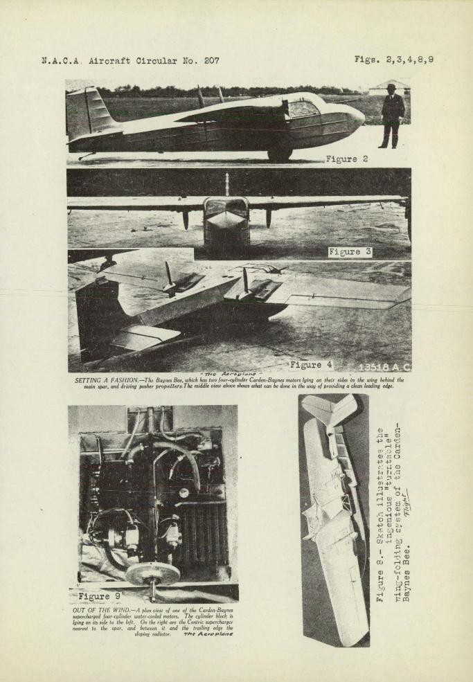
• Figure 9 ' OUT OF THE Wl.'5D.—.4 p/no view of one of ih4 Curdeo-Bnqnes supercharged four-cybnder water-cooled motors. The cqlnder bl00/ s lying on its side to the left. On the right are the Ci,m,i, oopernhssrger nearest to the spar, and between it and the trailing edge the
sloping radiator. T',e Ae.-pta,,
= C) 40 tlJ 05
a c 0
c ol C)
4 -1 -p Cr , 40 )= 5H
r1 O& rW -r
H 0
ocr. +0 C) t1 ••r.1
Ci) ---5
• '—C) dr
C-) C) 5H
-s IC)
r4 ',1 /1fl
N.A.C.A. Aircraft Circular No. 207
Figs. 2,3,4,8,9
i:ure4 SEIT1\; 1 —! he. hh has two fooe-cylmder Carden-Baynes 05010,5 lying on these soles in the wing be/nod the
morn spar, and driving posher p5-ops'llvr,t.The middle view above shows what can be done in the way of providing a clean leading edge.

N.A.C.A. Aircraft Circular No. 207 Figs. 7,12
Figure 7.—The Baynes Bee.