airborne surveys planning, logistics and safety 07 workshop.pdf · best rate of climb (vy, vyse),...
TRANSCRIPT
September 14, 20071 www.iagsa.ca
Airborne Surveys
Planning, Logistics and Safety
Toronto, Canada September 2007
Exploration 07
September 14, 20072 www.iagsa.ca
Presenters
John Issenman, IAGSA Chief Operating Officer
Stan Medved, Manager Aviation Safety - BHP Billiton, IAGSA Technical Committee Chair and Executive Committee Member
September 14, 20073 www.iagsa.ca
Airborne Surveys – Planning Logistics & Safety
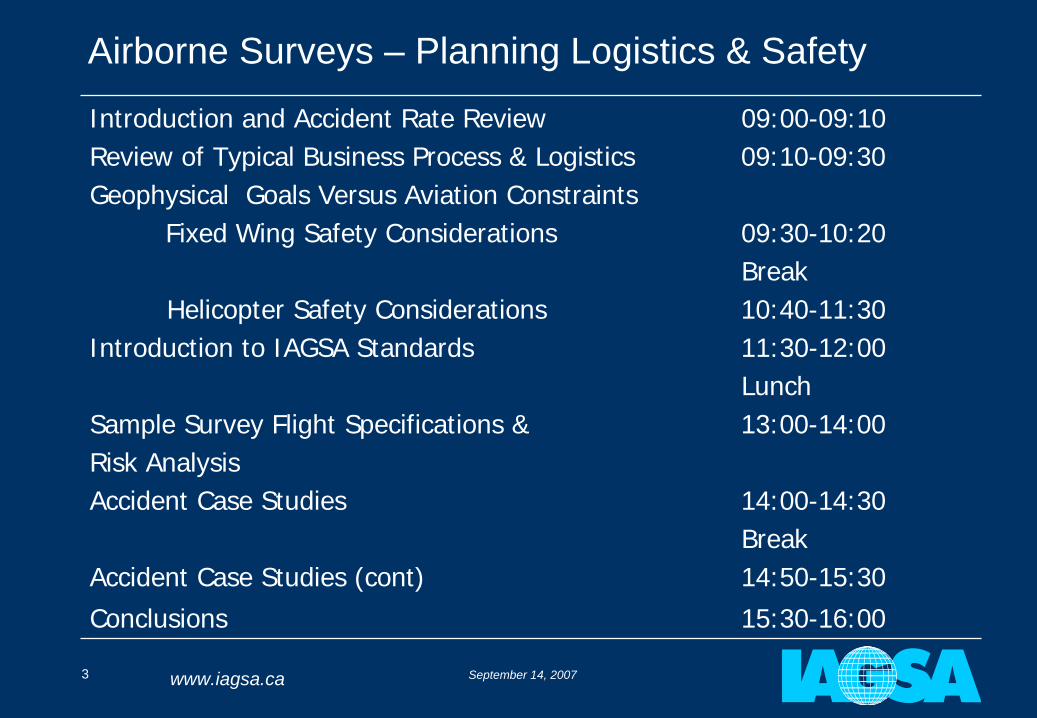
Introduction and Accident Rate Review 09:00-09:10Review of Typical Business Process & Logistics 09:10-09:30Geophysical Goals Versus Aviation Constraints
Fixed Wing Safety Considerations 09:30-10:20Break
Helicopter Safety Considerations 10:40-11:30Introduction to IAGSA Standards 11:30-12:00
LunchSample Survey Flight Specifications & 13:00-14:00Risk AnalysisAccident Case Studies 14:00-14:30
BreakAccident Case Studies (cont) 14:50-15:30Conclusions 15:30-16:00
September 14, 20074 www.iagsa.ca
Part 1:
Introduction and Accident Rate Review
John Issenman
September 14, 20075 www.iagsa.ca
Why form IAGSA?
After a particularly bad year in 1995 (5 aircraft lost; 10 fatalities) several survey companies decided to form the International Airborne Geophysics Safety Association (IAGSA)
Mandate:
To develop promote and enhance safety in the industry
Develop standards and recommended safety practices for survey operations
To serve as a repository of safety information relevant to the industry
To educate clients on the relevant safety topics to assist in writing appropriate contract specifications
September 14, 20076 www.iagsa.ca
What has IAGSA done so far?
Developed “Standards” and “Recommended Practices” for the industry; published in a Safety Policy Manual
Developed a “Recommended Contract Annex” based on the Safety Policy Manual for clients to add to their requirements (more on this later)
Gathered accident and activity data
Gathered safety advisories for sharing among members
September 14, 20077 www.iagsa.ca
What has IAGSA done so far?
Implemented an accreditation program to review Active Member compliance with IAGSA policies
Funded a special project to develop risk analysis tools for high elevation helicopter autorotations
Established website where much of the above information may be obtained www.iagsa.ca
September 14, 20078 www.iagsa.ca
How are we doing?
IAGSA gathers accident and activity data to develop meaningful accident rates
Each Active Member provides annual activity data (i.e. flying hours) for each category of aircraft
In addition, the number of fatal and non-fatal accidents is compiled
These data are used to calculation accident rates normalized to 100,000 flying hours – (convention aviation accident statistics throughout the world)
September 14, 20079 www.iagsa.ca
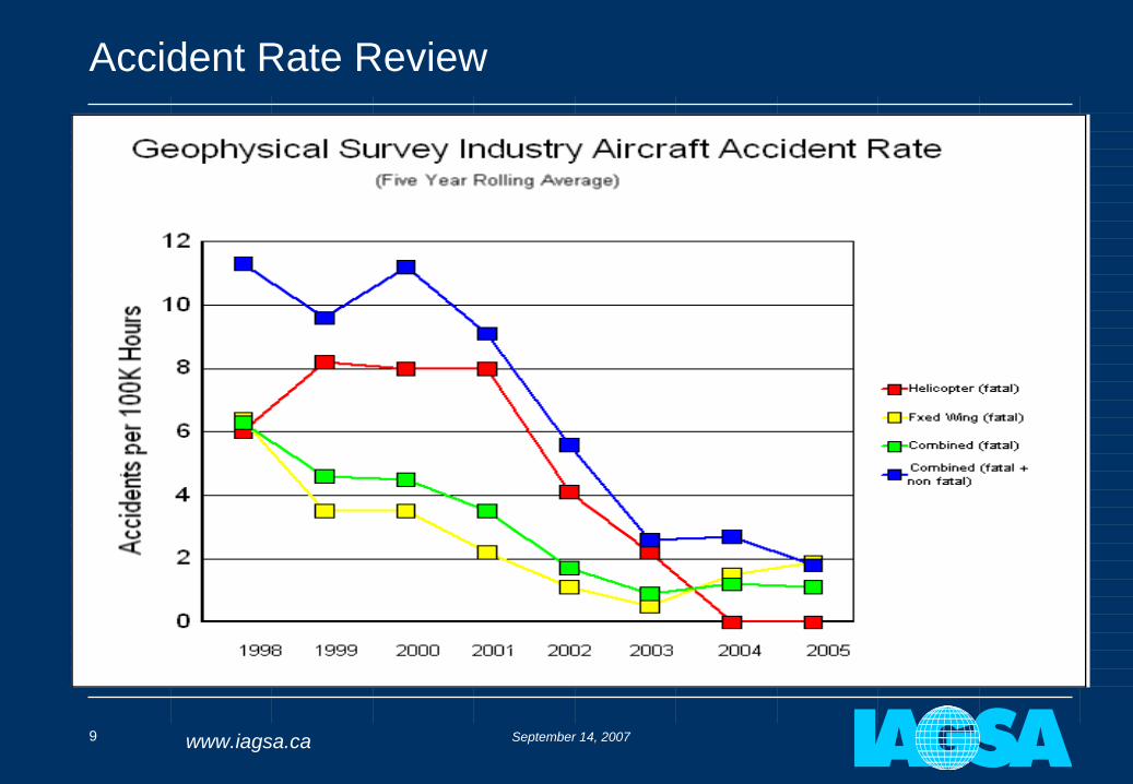
Accident Rate Review
September 14, 200710 www.iagsa.ca
Accident Rate Review
Airborne Geophysics Survey Industry overall accident rate (fixed and rotary wing) has come down from 11 in 1998 to 2 in 2005
Fatal rate over same time has come down from 6 to 1 per 100,000 hours
North American/European/Australian non-scheduled commercial air services (fixed and rotary) rates are approximately 10 (total) and 1 (fatal) per 100K hours, respectively
September 14, 200711 www.iagsa.ca
Accident Rate Observations
Since IAGSA inception, the accident rates have trended in the right direction
One in two survey accidents result in a fatality compared with one in ten for non airline commercial aviation
Analysis of survey accidents has shown:
the inability to clear high terrain while flying lines is a factor
high proportion of piston engine fixed wing aircraft
September 14, 200712 www.iagsa.ca
End of Part 1:
Introduction and Accident Rate Review
QUESTIONS?
September 14, 200713 www.iagsa.ca
Part 2:
Review of Typical Business Process
John Issenman
September 14, 200714 www.iagsa.ca
Step 1 – Tender Issue
A request for proposals or a tender document is issued to eligible bidders
The RFP specifies, among other things, how the client expects the survey to be flown
It is important that the client know what is “reasonable” to expect
from various aircraft
over differing terrain
with the desired survey equipment
September 14, 200715 www.iagsa.ca
Step 2 – Bid Preparation & Acceptance
A bid is prepared during which the bidder considers:
Suitable types of aircraft for the requested survey data and equipment
Terrain over which the survey it to be done
Specs for flying height, speed and data resolution
Costs
A risk assessment is completed to determine whether the survey can be completed safely as requested or with mitigations applied
If the answer is NO, it will be difficult to submit a conforming bid! (so will someone else bid on it?)
September 14, 200716 www.iagsa.ca
Step 3 – Crew Assembly
Field crew is assembled and mobilized:
One or two geophysicists or logisticians
One or two pilots
Possibly one onboard technician
Probably one Aircraft Maintenance Engineer (AME)
Risk analysis updated based on any amendments to contract and subject to crew input upon arrival on site
September 14, 200717 www.iagsa.ca
Step 4 – Logistics Support
Aircraft availability – Foreign registration of aircraft, aircraft modifications
Air Operator Certificate
Permits
Flight crew licensing
Fuel availability – pre-positioning may be required
Spare parts (aircraft and survey equipment)
Hangar access
Office and personnel accommodation
Security
September 14, 200718 www.iagsa.ca
Step 4 – Data Acquisition
First flights to assess validity of assumptions used in risk analysis (e.g.. determine suitability of digital terrain elevation model used and drape surface generated)
Geophysicists process data gathered daily for quality control.
Pilots fly grid lines and may monitor onboard survey equipment.
Technician or operator may monitor onboard survey equipment.
AME ensures aircraft can fly.
Geophysicist performs quality assurance and preliminary field processing
September 14, 200719 www.iagsa.ca
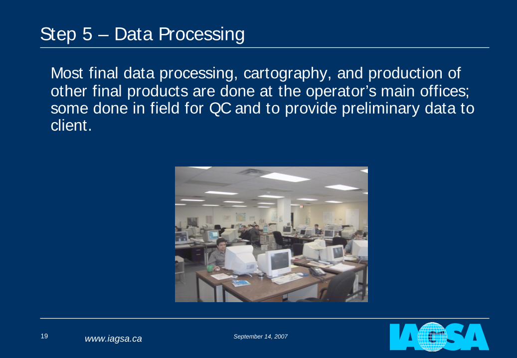
Step 5 – Data Processing
Most final data processing, cartography, and production of other final products are done at the operator’s main offices; some done in field for QC and to provide preliminary data to client.
September 14, 200720 www.iagsa.ca
September 14, 200721 www.iagsa.ca
End of Part 2:
Review of Typical Business Process
QUESTIONS?
September 14, 200722 www.iagsa.ca
Part 3 a:
Fixed-wing Safety Considerations In
Airborne GeophysicsStan Medved
September 14, 200723 www.iagsa.ca
Fixed Wing Safety Considerations
General factors – What are the goals? What Types of aircraft?
Speed – What does it mean for the geophysicist & the pilot?
Climbing and Descending – which is more demanding?
Multi-engine is always safer – isn’t it?
September 14, 200724 www.iagsa.ca
Fixed Wing Safety Considerations - General
Geophysicist’s goal:
To obtain the best possible data with available resources
How?
Fly low and slow
Increase number / size of sensors
Increase sampling rate
Improve sensor resolution
September 14, 200725 www.iagsa.ca
Fixed Wing Safety Considerations - General
Pilot’s goal:
To safely fly the task within survey specifications
How?
Operate the aircraft within manufacturers’ and regulatory limits
Use a risk management based approach
Regulatory requirements relating to survey flying are minimal compared with other commercial operations
September 14, 200726 www.iagsa.ca
Fixed Wing Safety Considerations - General
Aircraft types:
Typical aircraft are smaller single and twin engine piston and turboprop
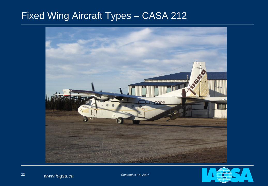
A few larger aircraft such as the Fugro Dash 7 and CASA 212
With a few exceptions aircraft have not been designed for continuous low level operations
• Performance implications• Affect on structural integrity• Inappropriate limitations
Aircraft need to be modified
September 14, 200727 www.iagsa.ca
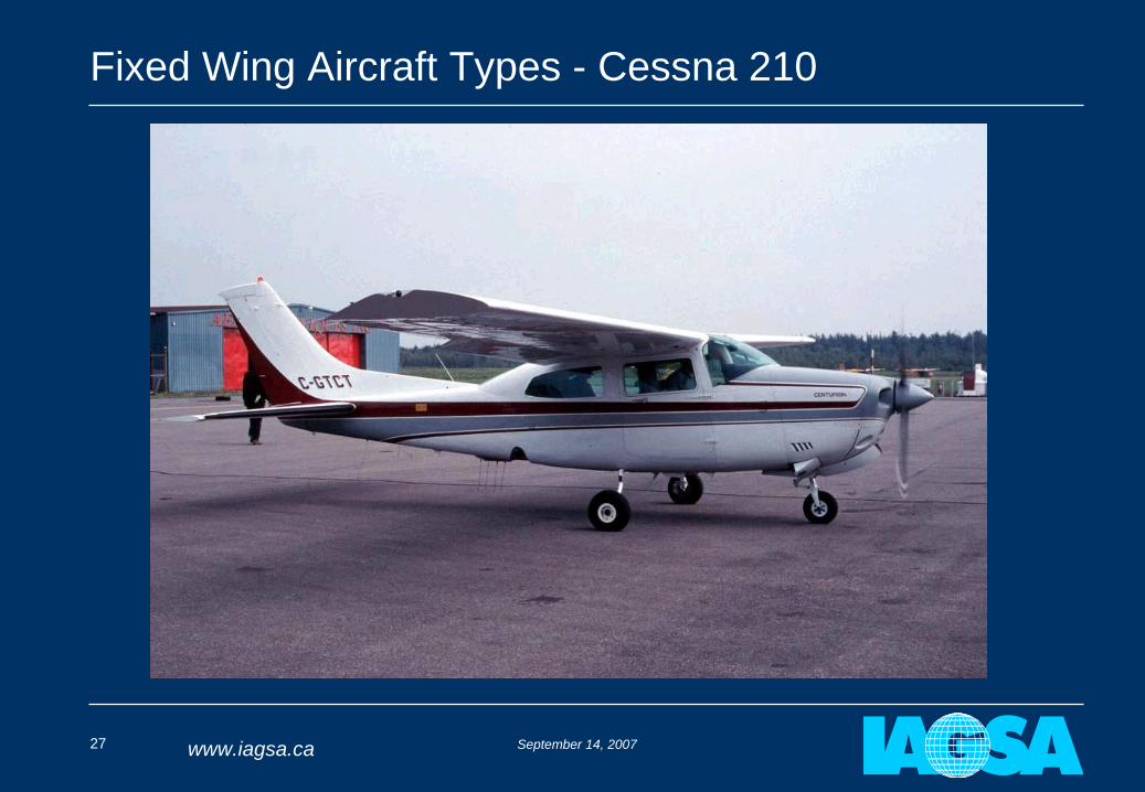
Fixed Wing Aircraft Types - Cessna 210
September 14, 200728 www.iagsa.ca
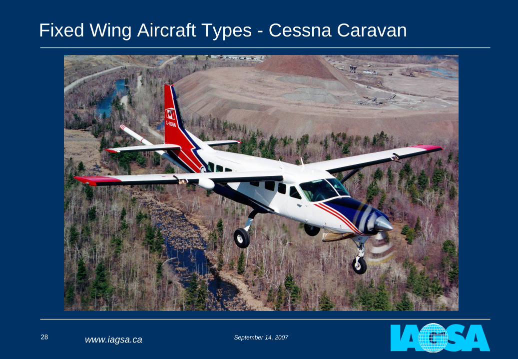
Fixed Wing Aircraft Types - Cessna Caravan
September 14, 200729 www.iagsa.ca
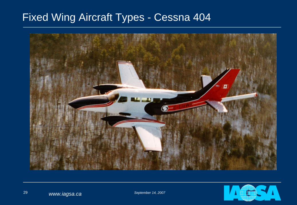
Fixed Wing Aircraft Types - Cessna 404
September 14, 200730 www.iagsa.ca
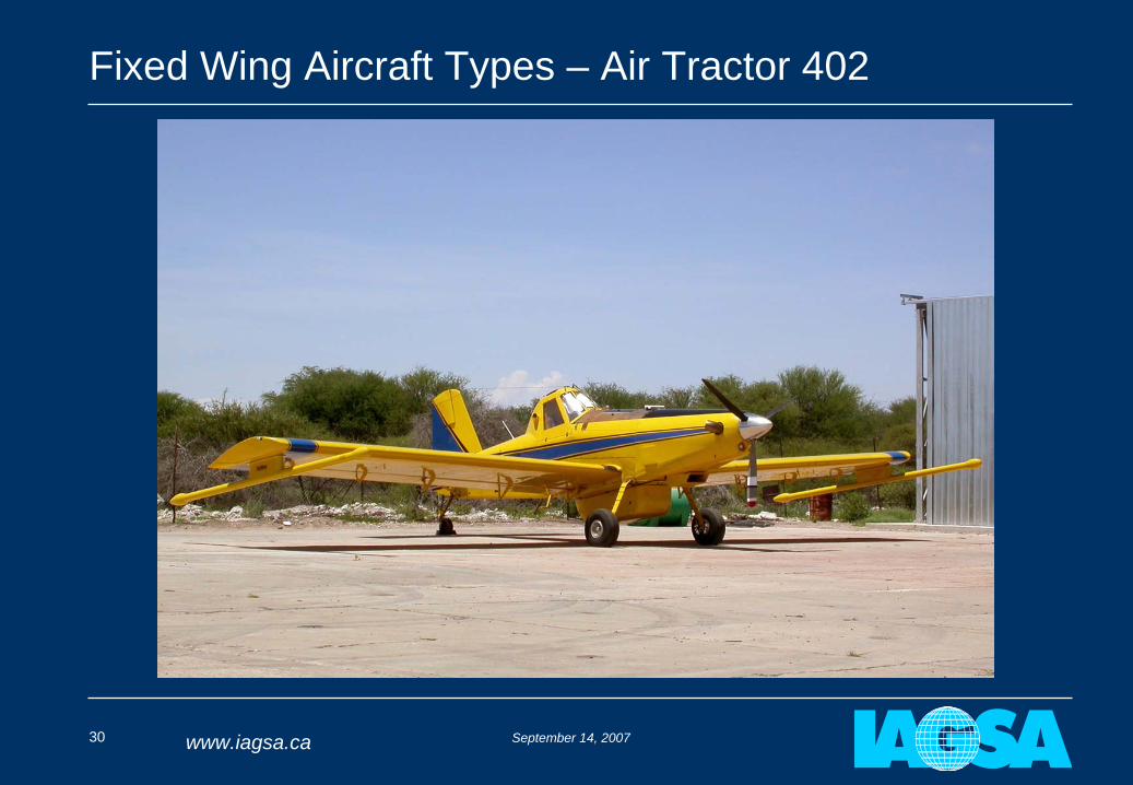
Fixed Wing Aircraft Types – Air Tractor 402
September 14, 200731 www.iagsa.ca
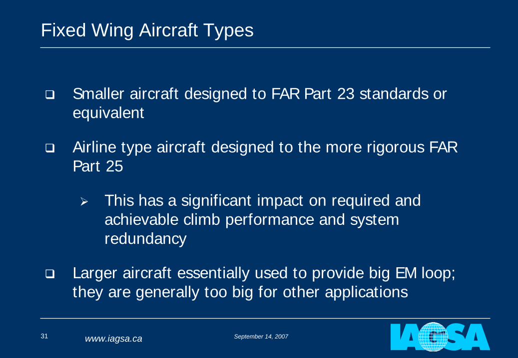
Fixed Wing Aircraft Types
Smaller aircraft designed to FAR Part 23 standards or equivalent
Airline type aircraft designed to the more rigorous FAR Part 25
This has a significant impact on required and achievable climb performance and system redundancy
Larger aircraft essentially used to provide big EM loop; they are generally too big for other applications
September 14, 200732 www.iagsa.ca
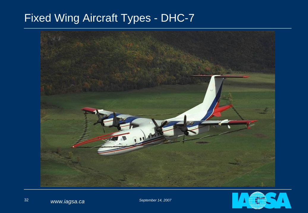
Fixed Wing Aircraft Types - DHC-7
September 14, 200733 www.iagsa.ca
Fixed Wing Aircraft Types – CASA 212
September 14, 200734 www.iagsa.ca
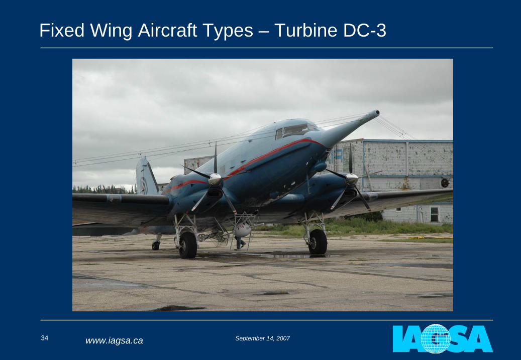
Fixed Wing Aircraft Types – Turbine DC-3
September 14, 200735 www.iagsa.ca
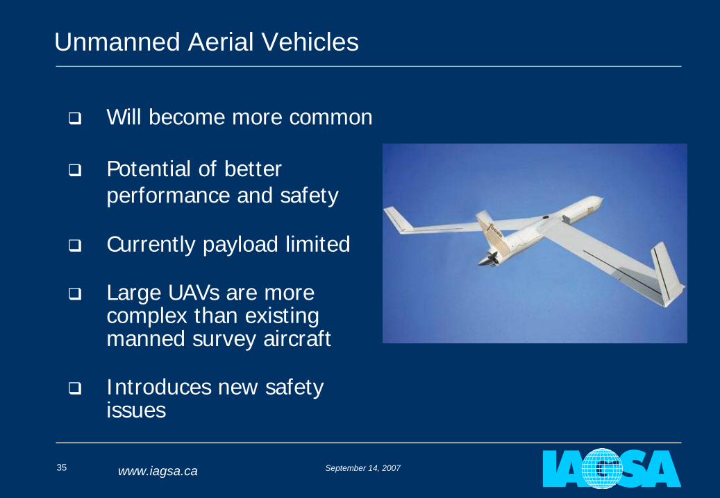
Unmanned Aerial Vehicles
Will become more common
Potential of better performance and safety
Currently payload limited
Large UAVs are more complex than existing manned survey aircraft
Introduces new safety issues
September 14, 200736 www.iagsa.ca
Fixed Wing Safety Considerations - Speed
The speed of an aircraft does not have the same meaning or implications for different people
Geophysicists are concerned with ground speed (GS)
Pilots are primarily concerned with Indicated Airspeed (IAS) followed by True Airspeed (TAS)
What’s the difference?
September 14, 200737 www.iagsa.ca
Fixed Wing Safety Considerations - Speed
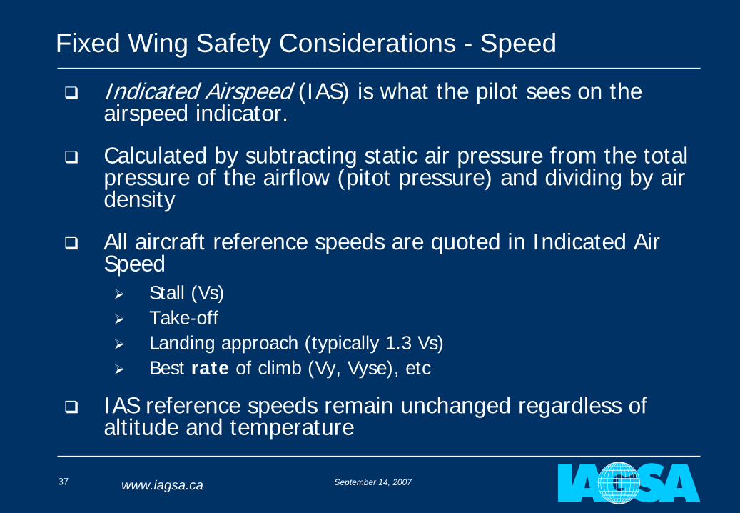
Indicated Airspeed (IAS) is what the pilot sees on the airspeed indicator.
Calculated by subtracting static air pressure from the total pressure of the airflow (pitot pressure) and dividing by air density
All aircraft reference speeds are quoted in Indicated Air Speed
Stall (Vs)
Take-off
Landing approach (typically 1.3 Vs)
Best rate of climb (Vy, Vyse), etc
IAS reference speeds remain unchanged regardless of altitude and temperature
September 14, 200738 www.iagsa.ca
Fixed Wing Safety Considerations - Speed
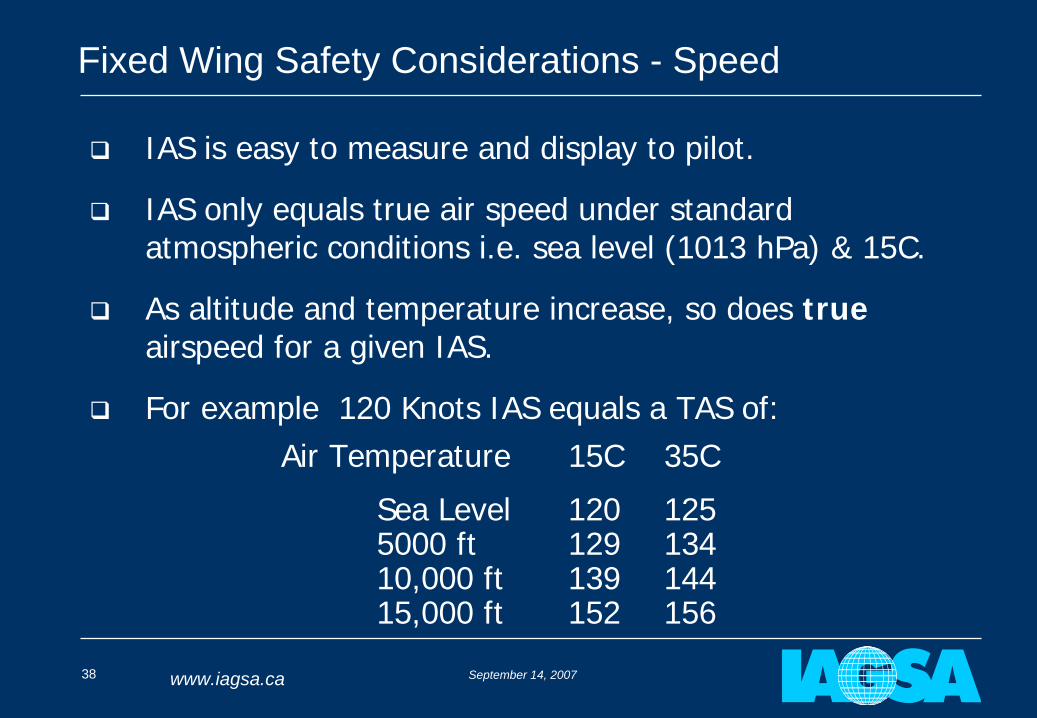
IAS is easy to measure and display to pilot.
IAS only equals true air speed under standard atmospheric conditions i.e. sea level (1013 hPa) & 15C.
As altitude and temperature increase, so does true airspeed for a given IAS.
For example 120 Knots IAS equals a TAS of:Air Temperature 15C 35C
Sea Level 120 1255000 ft 129 13410,000 ft 139 14415,000 ft 152 156
September 14, 200739 www.iagsa.ca
Fixed Wing Safety Considerations - Speed
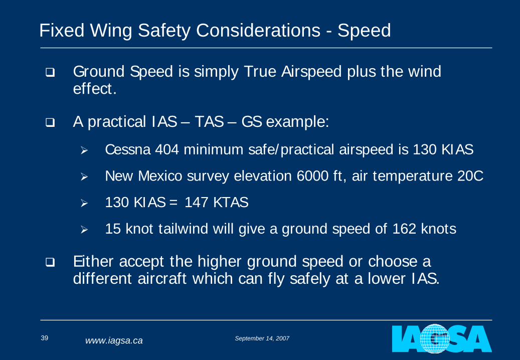
Ground Speed is simply True Airspeed plus the wind effect.
A practical IAS – TAS – GS example:
Cessna 404 minimum safe/practical airspeed is 130 KIAS
New Mexico survey elevation 6000 ft, air temperature 20C
130 KIAS = 147 KTAS
15 knot tailwind will give a ground speed of 162 knots
Either accept the higher ground speed or choose a different aircraft which can fly safely at a lower IAS.
September 14, 200740 www.iagsa.ca
Fixed Wing Safety Considerations - Speed
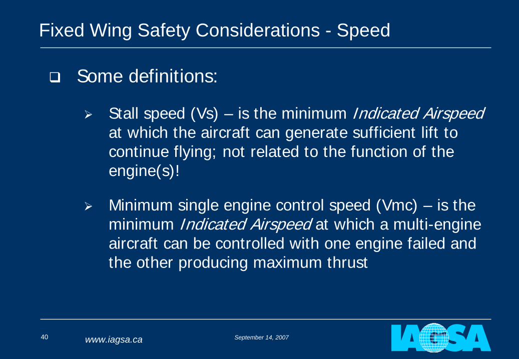
Some definitions:
Stall speed (Vs) – is the minimum Indicated Airspeed at which the aircraft can generate sufficient lift to continue flying; not related to the function of the engine(s)!
Minimum single engine control speed (Vmc) – is the minimum Indicated Airspeed at which a multi-engine aircraft can be controlled with one engine failed and the other producing maximum thrust
September 14, 200741 www.iagsa.ca
Fixed Wing Safety Considerations - Speed
Best single-engine rate of climb speed (Vyse) – is the Indicated Airspeed at which the aircraft will achieve the maximum climb rate with one engine operating at maximum thrust
September 14, 200742 www.iagsa.ca
Fixed Wing Safety Considerations - Speed
For higher data resolution, it is often desirable to fly at low speed
Turbulence, high nose up attitude, and turns make consistent flying at minimum flight manual speeds impractical and unsafe
IAGSA has developed a minimum speed standard for fixed wing aircraft which is the greater of:
130% of the clean stall speed (Vs)
110% of the recommended single engine climb speed (Vyse - multi-engine aircraft only)
September 14, 200743 www.iagsa.ca
Fixed Wing Safety Considerations - Speed
IAGSA minimum safe speed examples:
C404 120 knots (KIAS)
C208B 82 knots (KIAS)
These are not intended to be used as target survey speeds but are the lowest Indicated Airspeeds that a pilot should ever see while surveying and manoeuvring.
September 14, 200744 www.iagsa.ca
Fixed Wing Safety Considerations - Speed
Reasons for not flying slower:
You can fly right down to stall speed, but safety margins are eroded to the point where turbulence or a turn will cause the aircraft to stall. At survey heights recovery is unlikely.
You can fly below single engine control speed as long as both engines are operating – lose one and the aircraft will rapidly depart controlled flight.
You can fly below best single engine climb speed – but in the event of an engine failure, the only way to accelerate to this speed is to descend – in most cases not an option at survey heights.
Aircraft are more difficult to control at low speeds.
September 14, 200745 www.iagsa.ca
Fixed Wing Safety - Climbing and Descending
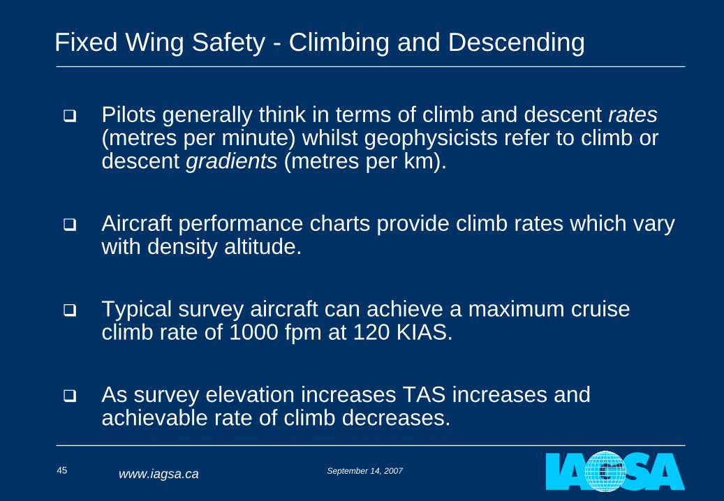
Pilots generally think in terms of climb and descent rates (metres per minute) whilst geophysicists refer to climb or descent gradients (metres per km).
Aircraft performance charts provide climb rates which vary with density altitude.
Typical survey aircraft can achieve a maximum cruise climb rate of 1000 fpm at 120 KIAS.
As survey elevation increases TAS increases and achievable rate of climb decreases.
September 14, 200746 www.iagsa.ca
Fixed Wing Safety - Climbing and Descending
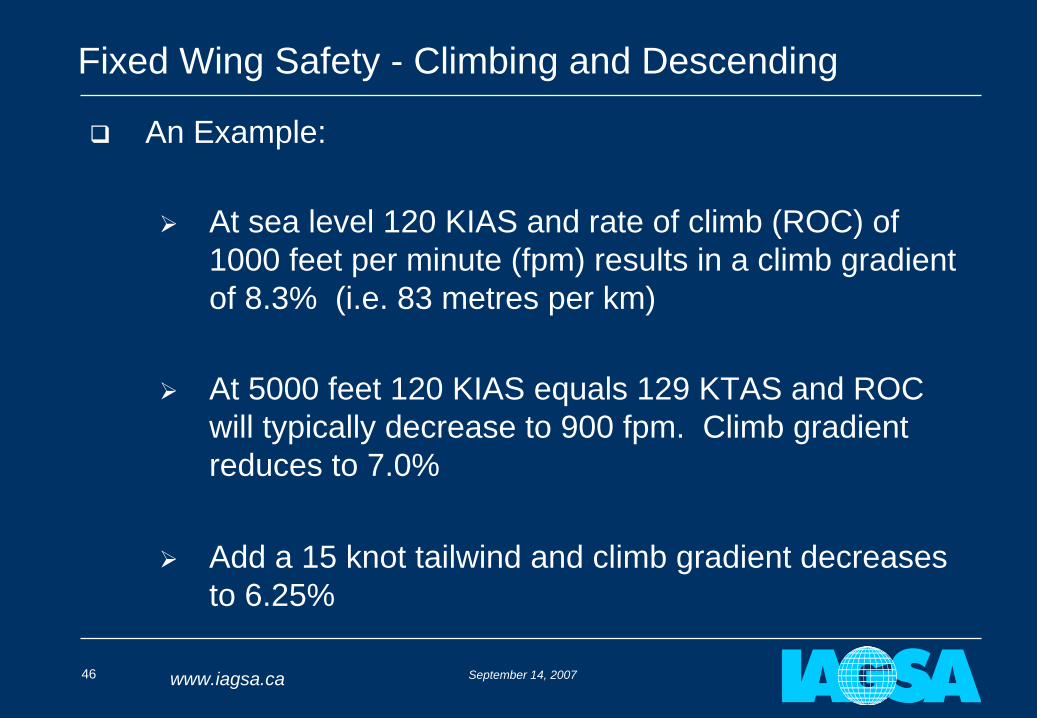
An Example:
At sea level 120 KIAS and rate of climb (ROC) of 1000 feet per minute (fpm) results in a climb gradient of 8.3% (i.e. 83 metres per km)
At 5000 feet 120 KIAS equals 129 KTAS and ROC will typically decrease to 900 fpm. Climb gradient reduces to 7.0%
Add a 15 knot tailwind and climb gradient decreases to 6.25%
September 14, 200747 www.iagsa.ca
Fixed Wing Safety - Climbing and Descending
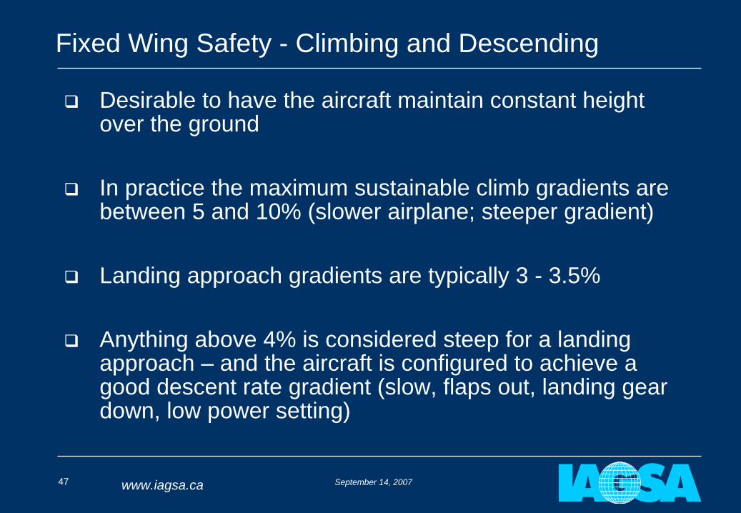
Desirable to have the aircraft maintain constant height over the ground
In practice the maximum sustainable climb gradients are between 5 and 10% (slower airplane; steeper gradient)
Landing approach gradients are typically 3 - 3.5%
Anything above 4% is considered steep for a landing approach – and the aircraft is configured to achieve a good descent rate gradient (slow, flaps out, landing gear down, low power setting)
September 14, 200748 www.iagsa.ca
Fixed Wing Safety - Climbing and Descending
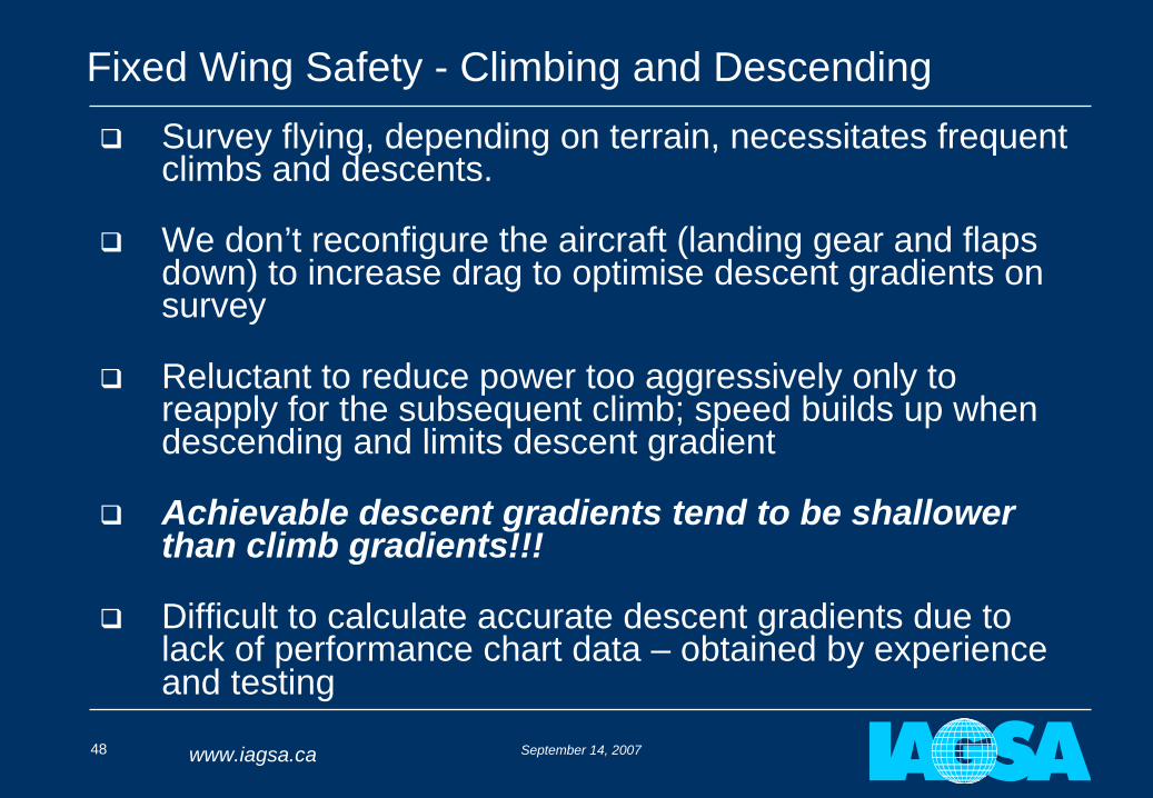
Survey flying, depending on terrain, necessitates frequent climbs and descents.
We don’t reconfigure the aircraft (landing gear and flaps down) to increase drag to optimise descent gradients on survey
Reluctant to reduce power too aggressively only to reapply for the subsequent climb; speed builds up when descending and limits descent gradient
Achievable descent gradients tend to be shallower than climb gradients!!!
Difficult to calculate accurate descent gradients due to lack of performance chart data – obtained by experience and testing
September 14, 200749 www.iagsa.ca
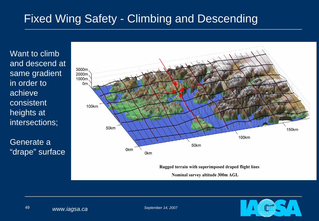
Fixed Wing Safety - Climbing and Descending
Want to climb and descend at same gradient in order to achieve consistent heights at intersections;
Generate a “drape” surface
September 14, 200750 www.iagsa.ca
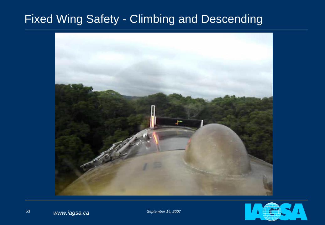
Fixed Wing Safety - Climbing and Descending
Over such steep terrain we “drape” the surface to match the aircraft’s performance; descent performance is usually the limiting factor
The quality of the “drape” depends on the accuracy of the digital elevation data used – much of it is still insufficient for this purpose
Pilots need to be ready for errors in drape and have some performance margin available as shown in the following example:
September 14, 200751 www.iagsa.ca
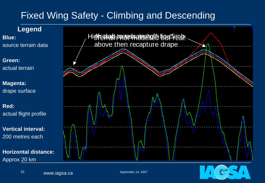
Fixed Wing Safety - Climbing and DescendingLegend
Blue:source terrain data
Green:actual terrain
Magenta:drape surface
Red:actual flight profile
Vertical interval:200 metres each
Horizontal distance:Approx 20 km
High due to terrain “off-line”Terrain not modelled but real!Aircraft needs margin to climbabove then recapture drape
September 14, 200752 www.iagsa.ca
Fixed Wing Safety - Climbing and Descending
September 14, 200753 www.iagsa.ca
Fixed Wing Safety - Climbing and Descending
September 14, 200754 www.iagsa.ca
Fixed Wing Safety - Single Engine Vs Twin Engine
“Twin engine aircraft are safer than single engine aircraft”
Based on the premise if an engine fails the aircraft can return to an airport on the remaining engine
September 14, 200755 www.iagsa.ca
Failure Rates for Turbine and Piston Engines
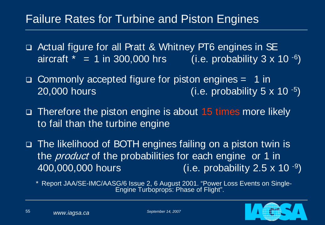
Actual figure for all Pratt & Whitney PT6 engines in SE aircraft * = 1 in 300,000 hrs (i.e. probability 3 x 10 -6)
Commonly accepted figure for piston engines = 1 in 20,000 hours (i.e. probability 5 x 10 -5)
Therefore the piston engine is about 15 times more likely to fail than the turbine engine
The likelihood of BOTH engines failing on a piston twin is the product of the probabilities for each engine or 1 in 400,000,000 hours (i.e. probability 2.5 x 10 -9)* Report JAA/SE-IMC/AASG/6 Issue 2, 6 August 2001. “Power Loss Events on Single-
Engine Turboprops: Phase of Flight”.
September 14, 200756 www.iagsa.ca
Fixed Wing Safety - Single Engine Vs Twin Engine
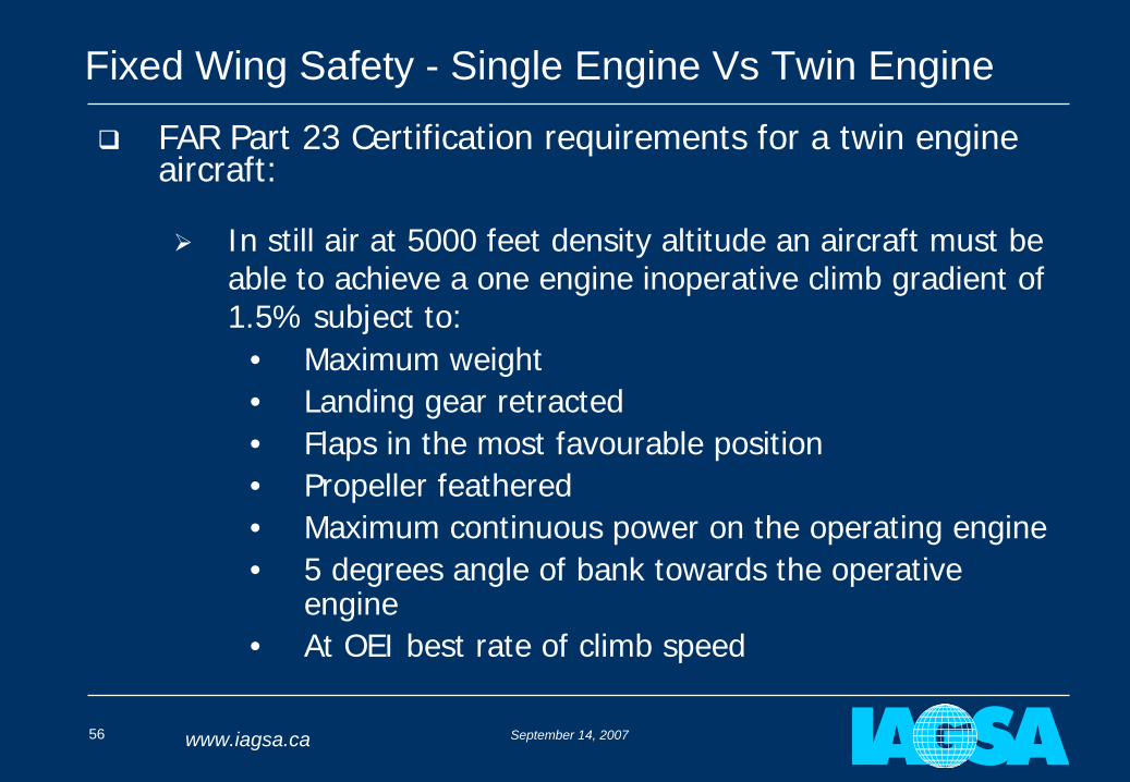
FAR Part 23 Certification requirements for a twin engine aircraft:
In still air at 5000 feet density altitude an aircraft must be able to achieve a one engine inoperative climb gradient of 1.5% subject to:
• Maximum weight• Landing gear retracted• Flaps in the most favourable position• Propeller feathered• Maximum continuous power on the operating engine• 5 degrees angle of bank towards the operative
engine• At OEI best rate of climb speed
September 14, 200757 www.iagsa.ca
Fixed Wing Safety - Single Engine Vs Twin Engine
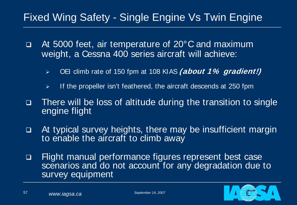
At 5000 feet, air temperature of 20°C and maximum weight, a Cessna 400 series aircraft will achieve:
OEI climb rate of 150 fpm at 108 KIAS (about 1% gradient!)
If the propeller isn’t feathered, the aircraft descends at 250 fpm
There will be loss of altitude during the transition to single engine flight
At typical survey heights, there may be insufficient margin to enable the aircraft to climb away
Flight manual performance figures represent best case scenarios and do not account for any degradation due to survey equipment
September 14, 200758 www.iagsa.ca
Fixed Wing Safety - Single Engine Vs Twin Engine
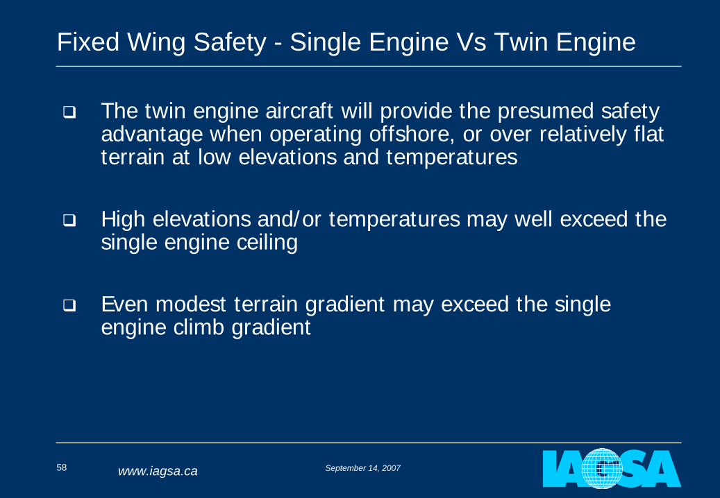
The twin engine aircraft will provide the presumed safety advantage when operating offshore, or over relatively flat terrain at low elevations and temperatures
High elevations and/or temperatures may well exceed the single engine ceiling
Even modest terrain gradient may exceed the single engine climb gradient
September 14, 200759 www.iagsa.ca
Fixed Wing Safety - Single Engine Vs Twin Engine
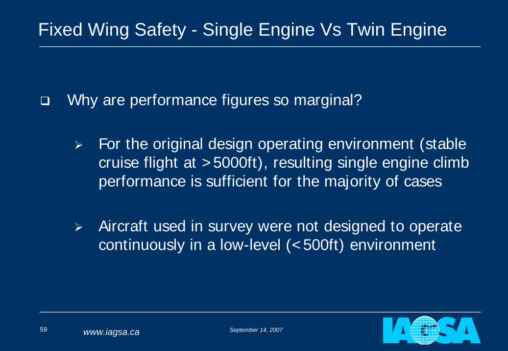
Why are performance figures so marginal?
For the original design operating environment (stable cruise flight at >5000ft), resulting single engine climb performance is sufficient for the majority of cases
Aircraft used in survey were not designed to operate continuously in a low-level (<500ft) environment
September 14, 200760 www.iagsa.ca
Fixed Wing Safety - Single Engine Vs Twin Engine
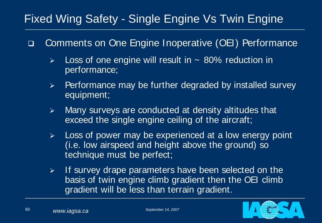
Comments on One Engine Inoperative (OEI) Performance
Loss of one engine will result in ~ 80% reduction in performance;
Performance may be further degraded by installed survey equipment;
Many surveys are conducted at density altitudes that exceed the single engine ceiling of the aircraft;
Loss of power may be experienced at a low energy point (i.e. low airspeed and height above the ground) so technique must be perfect;
If survey drape parameters have been selected on the basis of twin engine climb gradient then the OEI climb gradient will be less than terrain gradient.
September 14, 200761 www.iagsa.ca
Fixed Wing Safety - Single Engine Vs Twin Engine
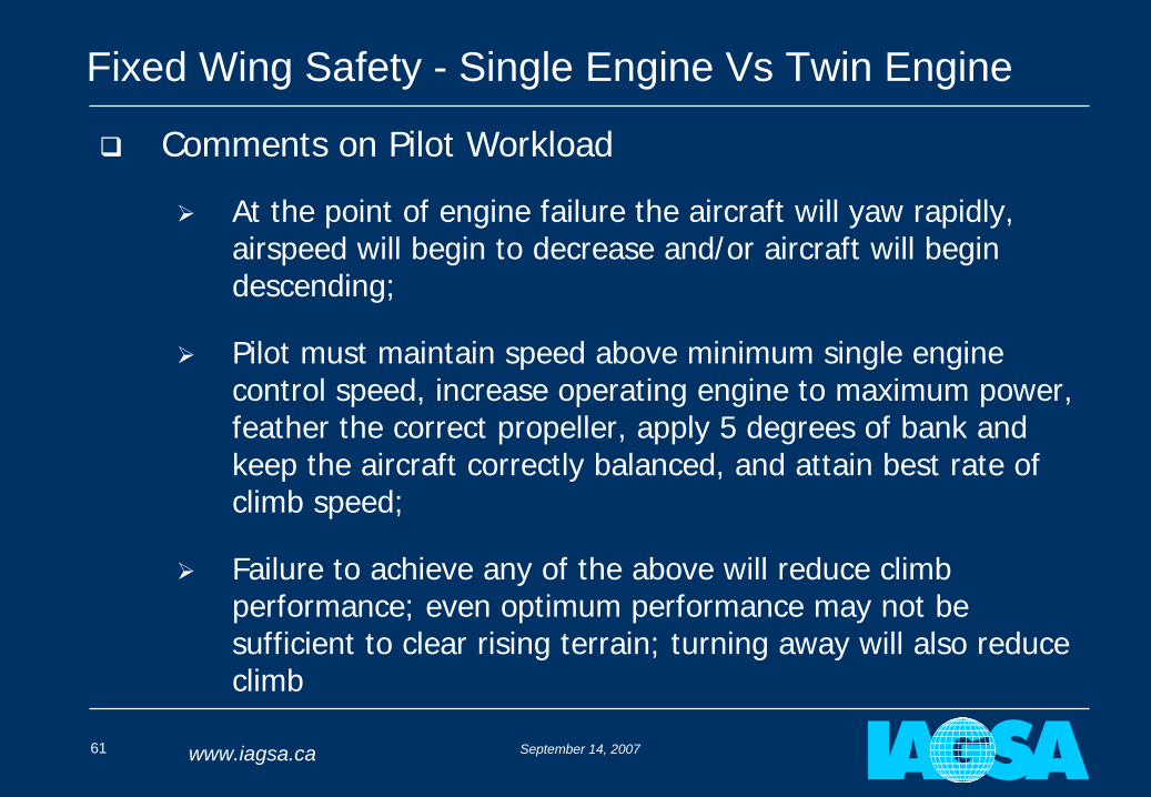
Comments on Pilot Workload
At the point of engine failure the aircraft will yaw rapidly, airspeed will begin to decrease and/or aircraft will begin descending;
Pilot must maintain speed above minimum single engine control speed, increase operating engine to maximum power, feather the correct propeller, apply 5 degrees of bank and keep the aircraft correctly balanced, and attain best rate of climb speed;
Failure to achieve any of the above will reduce climb performance; even optimum performance may not be sufficient to clear rising terrain; turning away will also reduce climb
September 14, 200762 www.iagsa.ca
Fixed Wing Safety - Single Engine Vs Twin Engine
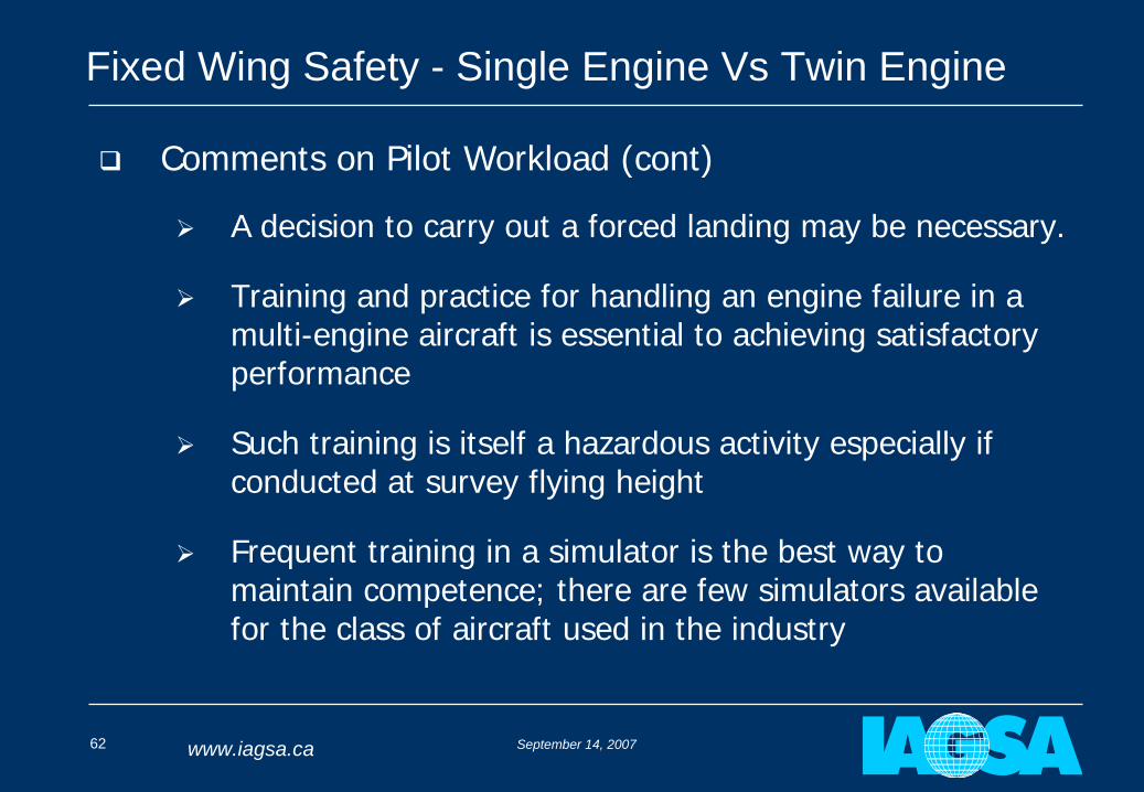
Comments on Pilot Workload (cont)
A decision to carry out a forced landing may be necessary.
Training and practice for handling an engine failure in a multi-engine aircraft is essential to achieving satisfactory performance
Such training is itself a hazardous activity especially if conducted at survey flying height
Frequent training in a simulator is the best way to maintain competence; there are few simulators available for the class of aircraft used in the industry
September 14, 200763 www.iagsa.ca
Fixed Wing Safety - Single Engine Vs Twin Engine
September 14, 200764 www.iagsa.ca
Fixed Wing Safety - Single Engine Vs Twin Engine
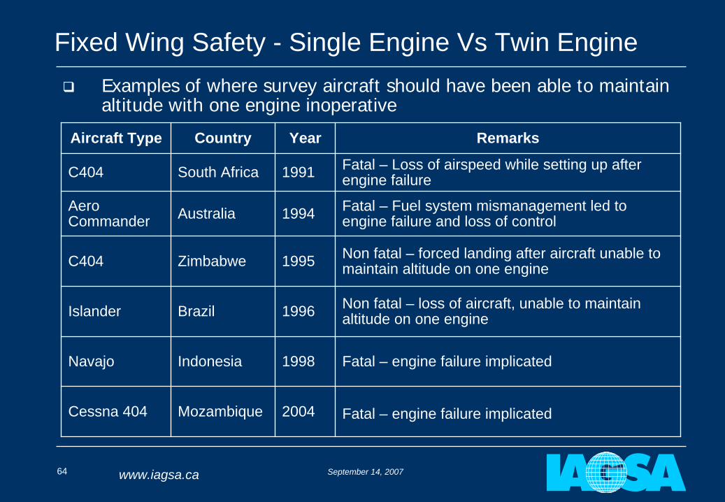
Examples of where survey aircraft should have been able to maintain altitude with one engine inoperative
Aircraft Type Country Year Remarks
C404 South Africa 1991 Fatal – Loss of airspeed while setting up after engine failure
Aero Commander Australia 1994 Fatal – Fuel system mismanagement led to
engine failure and loss of control
C404 Zimbabwe 1995 Non fatal – forced landing after aircraft unable to maintain altitude on one engine
Islander Brazil 1996 Non fatal – loss of aircraft, unable to maintain altitude on one engine
Navajo Indonesia 1998 Fatal – engine failure implicated
Cessna 404 Mozambique 2004 Fatal – engine failure implicated
September 14, 200765 www.iagsa.ca
Fixed Wing Safety - Single Engine Vs Twin Engine
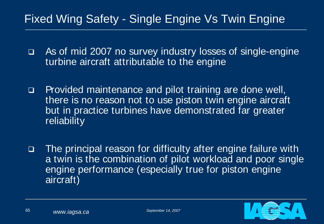
As of mid 2007 no survey industry losses of single-engine turbine aircraft attributable to the engine
Provided maintenance and pilot training are done well, there is no reason not to use piston twin engine aircraft but in practice turbines have demonstrated far greater reliability
The principal reason for difficulty after engine failure with a twin is the combination of pilot workload and poor single engine performance (especially true for piston engine aircraft)
September 14, 200766 www.iagsa.ca
Fixed Wing Safety - Single Engine Vs Twin Engine
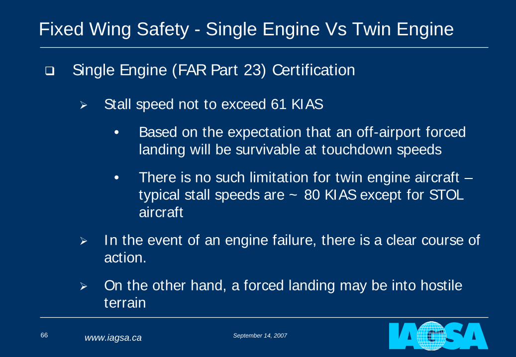
Single Engine (FAR Part 23) Certification
Stall speed not to exceed 61 KIAS
• Based on the expectation that an off-airport forced landing will be survivable at touchdown speeds
• There is no such limitation for twin engine aircraft – typical stall speeds are ~ 80 KIAS except for STOL aircraft
In the event of an engine failure, there is a clear course of action.
On the other hand, a forced landing may be into hostile terrain
September 14, 200767 www.iagsa.ca
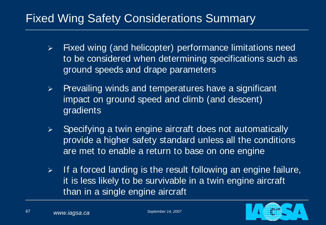
Fixed Wing Safety Considerations Summary
Fixed wing (and helicopter) performance limitations need to be considered when determining specifications such as ground speeds and drape parameters
Prevailing winds and temperatures have a significant impact on ground speed and climb (and descent) gradients
Specifying a twin engine aircraft does not automatically provide a higher safety standard unless all the conditions are met to enable a return to base on one engine
If a forced landing is the result following an engine failure, it is less likely to be survivable in a twin engine aircraft than in a single engine aircraft

September 14, 200768 www.iagsa.ca
End of Part 3 a:
Fixed Wing Safety Considerations
QUESTIONS?
September 14, 200769 www.iagsa.ca
BREAK!
September 14, 200770 www.iagsa.ca
Part 3 b:
Helicopter Safety Considerations
In
Airborne GeophysicsJohn Issenman
September 14, 200771 www.iagsa.ca
Helicopter Safety Considerations
Safety considerations for fixed wing aircraft apply equally to helicopters (eg. IAS – TAS, single vs. twin, min safe speeds)
Many projects in mountainous areas require use of helicopters at high elevations
Can deliver better survey data because they can fly slower and climb steeper; therefore contour steep terrain more successfully than fixed wing
Usually light, single engine models such as Eurocopter AS 350 series are chosen but some twins also used
September 14, 200772 www.iagsa.ca
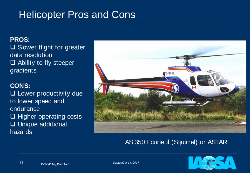
Helicopter Pros and Cons
PROS:
Slower flight for greater data resolution
Ability to fly steeper gradients
CONS:
Lower productivity due to lower speed and endurance Higher operating costs
Unique additional hazards
AS 350 Ecurieul (Squirrel) or ASTAR
September 14, 200773 www.iagsa.ca
Helicopter Autorotations
In the event of an engine failure, a helicopter can perform an autorotation to land safely
Successful autorotation is limited to certain combinations of height above ground (h) and speed (v)
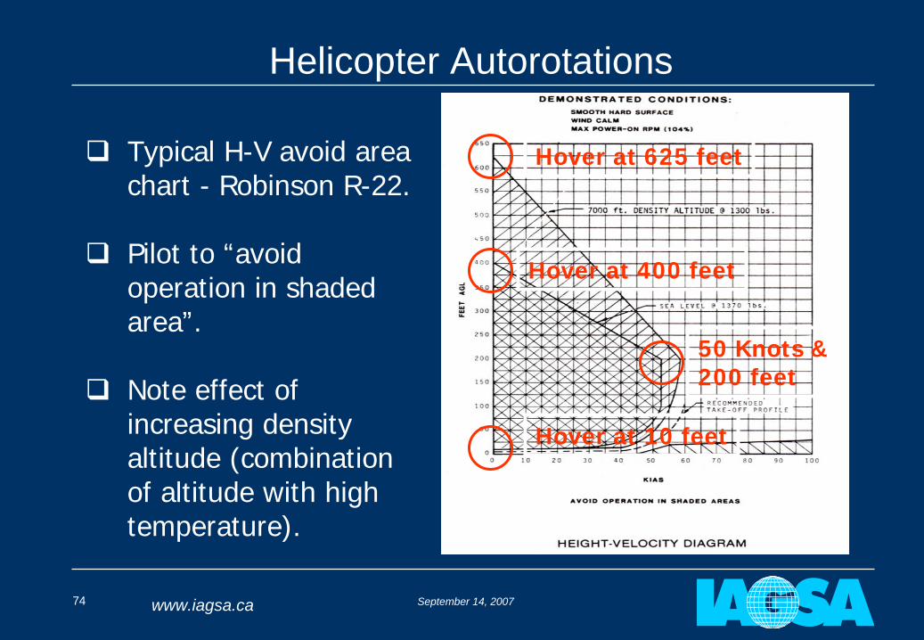
Pilot is provided with a chart of the H-V avoid area within which an autorotation may not be successful
September 14, 200774 www.iagsa.ca
Helicopter Autorotations
Typical H-V avoid area chart - Robinson R-22.
Pilot to “avoid operation in shaded area”.
Note effect of increasing density altitude (combination of altitude with high temperature).
Hover at 400 feet
50 Knots & 200 feet
Hover at 10 feet
Hover at 625 feet
September 14, 200775 www.iagsa.ca
Helicopter Autorotations
Pilot procedure in event of engine failure(AS350)
Lower collective pitch control (left hand) to prevent loss of rotor speed
Establish 65 knots using cyclic control (right hand)
Turn into wind
At 65 ft (20 m) flare to nose up attitude
At 20-25 ft (6-8 m) and constant attitude apply collective pitch to reduce sink rate
Resume level attitude, cancel sideslip, touch down
Notes say to expect 1800 ft/min descent at 65 knots
That’s 10 seconds from 300 feet!!
That’s why we want to minimize time spent in “avoid area”
September 14, 200776 www.iagsa.ca
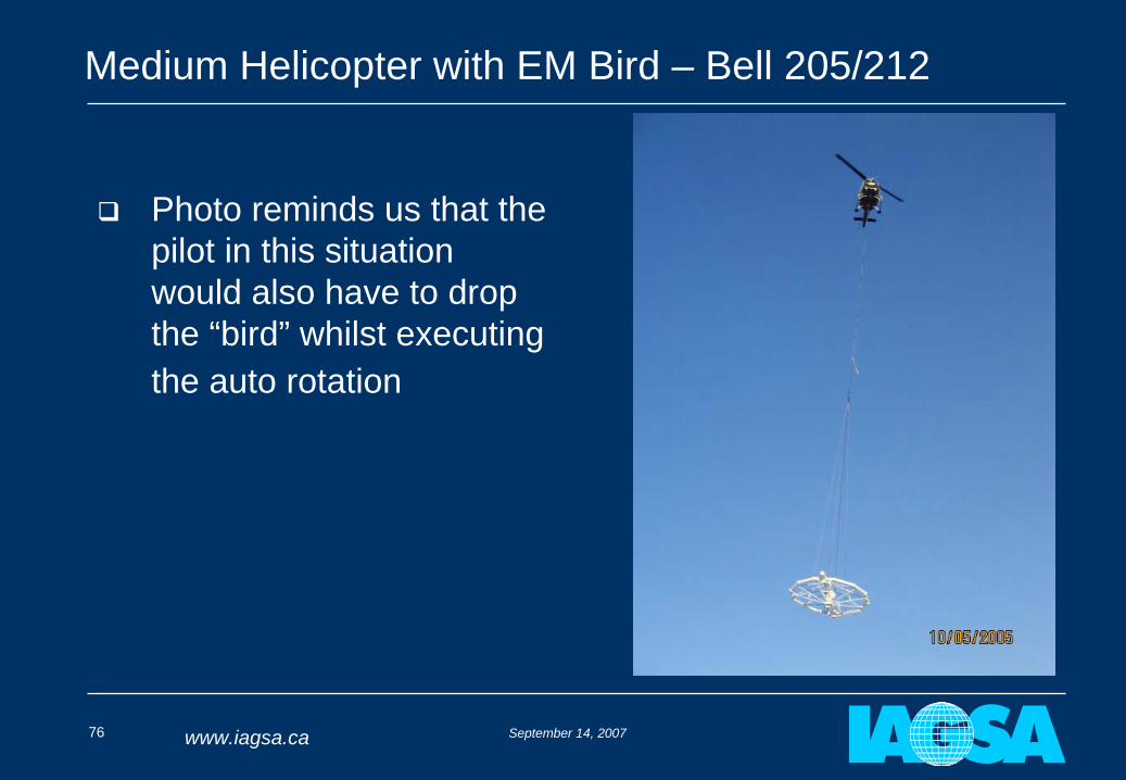
Medium Helicopter with EM Bird – Bell 205/212
Photo reminds us that the pilot in this situation would also have to drop the “bird” whilst executing the auto rotation
September 14, 200777 www.iagsa.ca
Helicopter Autorotations
September 14, 200778 www.iagsa.ca
Good Training – Good Outcome
September 14, 200779 www.iagsa.ca
Helicopter Safety Considerations – HOGE
IAGSA recommends that “Hover-out-of-ground-effect” (HOGE) capability should be the performance benchmark for helicopters
A helicopter can hover “in-ground-effect” (HIGE) at a higher weight than when far above the ground
To be in ground effect requires that the helicopter be no more than about half a rotor diameter above a level solid surface
Operating with HOGE capability means the pilot has some extra margin for downdrafts, or unexpected circumstances (like the unexpected terrain shown earlier!)
September 14, 200780 www.iagsa.ca
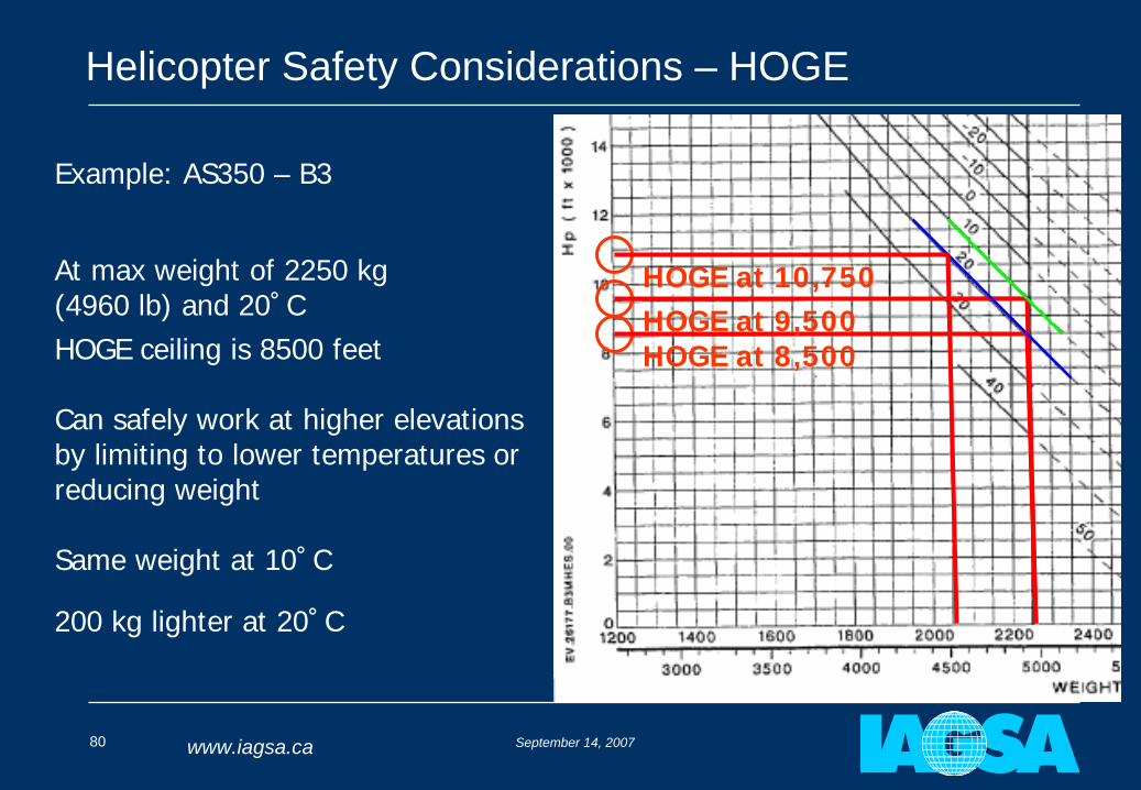
Helicopter Safety Considerations – HOGE
HOGE ceiling is 8500 feet HOGE at 8,500
HOGE at 10,750HOGE at 9,500
At max weight of 2250 kg (4960 lb) and 20˚C
Example: AS350 – B3
Can safely work at higher elevations by limiting to lower temperatures or reducing weight
200 kg lighter at 20˚C
Same weight at 10˚C
September 14, 200781 www.iagsa.ca
Helicopter Safety Considerations
Twin Engine Helicopters
Most cannot land in a confined area vertically with one engine inoperative (OEI)
Maximum altitude with OEI tends to be low
• Bell 412EP OEI service ceiling:
Max weight – 5400 ft
Mid weight – 8400 ft
At moderate to high elevation surveys failure of one engine will result in a forced landing
September 14, 200782 www.iagsa.ca
Helicopter Safety Considerations
Other Helicopter Specific Considerations
Dynamic roll over
Ground resonance
Run on landing – tail rotor failures
The landing area (size, surface, obstacles) has a significant impact
Settling with power
Wire strikes
Towed bird strikes
Tail rotor strikes
September 14, 200783 www.iagsa.ca
Helicopter Safety Considerations
September 14, 200784 www.iagsa.ca
Helicopter Safety Considerations - Summary
Helicopters offer advantages because of slower speed and steeper gradients
Can operate away from airfields but the landing area needs to be carefully considered
Minimum survey speed to remain outside the H-V avoid area
Operate at weights that give a HOGE capability
Autorotative landings happen very quickly
There is no manufacturer data available to determine successful autorotation parameters at high elevations
Twin engine helicopters are unlikely to remain airborne following an engine failure at moderate to high survey elevations
September 14, 200785 www.iagsa.ca
End of Part 3 b:
Helicopter Safety Considerations
QUESTIONS?
September 14, 200786 www.iagsa.ca
Part 5:
Introduction to IAGSA Standards
John Issenman
September 14, 200787 www.iagsa.ca
Introduction to IAGSA Standards
Standards and Recommended Practices described in Safety Policy Manual with background information
Based on ICAO format
Also written in the form of a contractual clauses in the IAGSA Contract Annex for suggested use by those writing specifications.
The international oil industry through the Association of Oil and Gas Producers has adopted IAGSA Recommended Practices
September 14, 200788 www.iagsa.ca
Introduction to IAGSA Standards
All Active Members agree to substantially comply with these and must demonstrate this as a condition of Accreditation
An Active Member who does not comply with one or more Standards, makes a declaration in the form of a “Notification of Difference”
September 14, 200789 www.iagsa.ca
Introduction to IAGSA Standards
Examples of some standards
Definitions
Flying height to be determined after risk analysis following a recommended format
Minimum speed for fixed wing aircraft
Use of helmets
Pilot training syllabus
Equipment required for over water and offshore surveys
Helicopter performance benchmarks
Helicopter avoid area recommendation
September 14, 200790 www.iagsa.ca
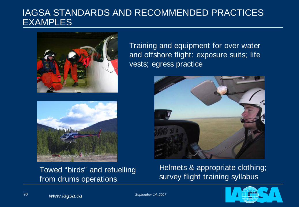
IAGSA STANDARDS AND RECOMMENDED PRACTICES EXAMPLES
Training and equipment for over water and offshore flight: exposure suits; life vests; egress practice
Helmets & appropriate clothing;survey flight training syllabus
Towed “birds” and refuellingfrom drums operations
September 14, 200791 www.iagsa.ca
End of Part 5:
Introduction to IAGSA Standards
QUESTIONS?
September 14, 200792 www.iagsa.ca
LUNCH
September 14, 200793 www.iagsa.ca
Part 6:
Sample Survey Flight Specifications and Typical Risk Analyses
Stan Medved
September 14, 200794 www.iagsa.ca
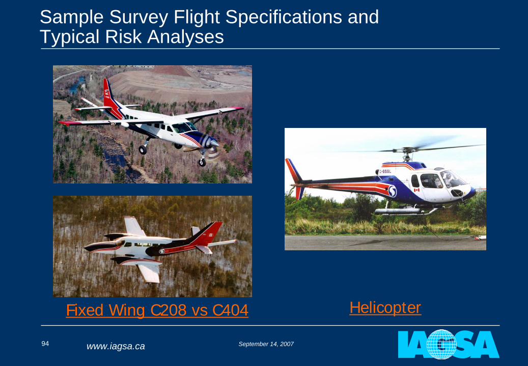
Sample Survey Flight Specifications and Typical Risk Analyses
Fixed Wing C208 vs C404 Helicopter
September 14, 200795 www.iagsa.ca
Risk Analysis - General
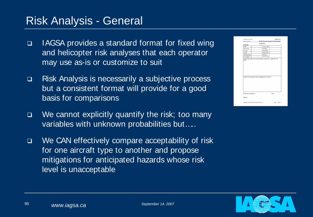
IAGSA provides a standard format for fixed wing and helicopter risk analyses that each operator may use as-is or customize to suit
Risk Analysis is necessarily a subjective process but a consistent format will provide for a good basis for comparisons
We cannot explicitly quantify the risk; too many variables with unknown probabilities but…..
We CAN effectively compare acceptability of risk for one aircraft type to another and propose mitigations for anticipated hazards whose risk level is unacceptable
September 14, 200796 www.iagsa.ca
Risk Analysis - General
Note that airborne geophysics hazards are often unlike those for air transport operation
For example: Controlled Flight Into Terrain (CFIT) is one of the major causes of aircraft accidents in both airline and airborne geophysics operations; but for different reasons
Mitigating strategies applicable to airline operations are often incompatible with airborne geophysics: airlines use EGPWS to combat CFIT but this equipment is totally useless for low level airborne geophysics
September 14, 200797 www.iagsa.ca
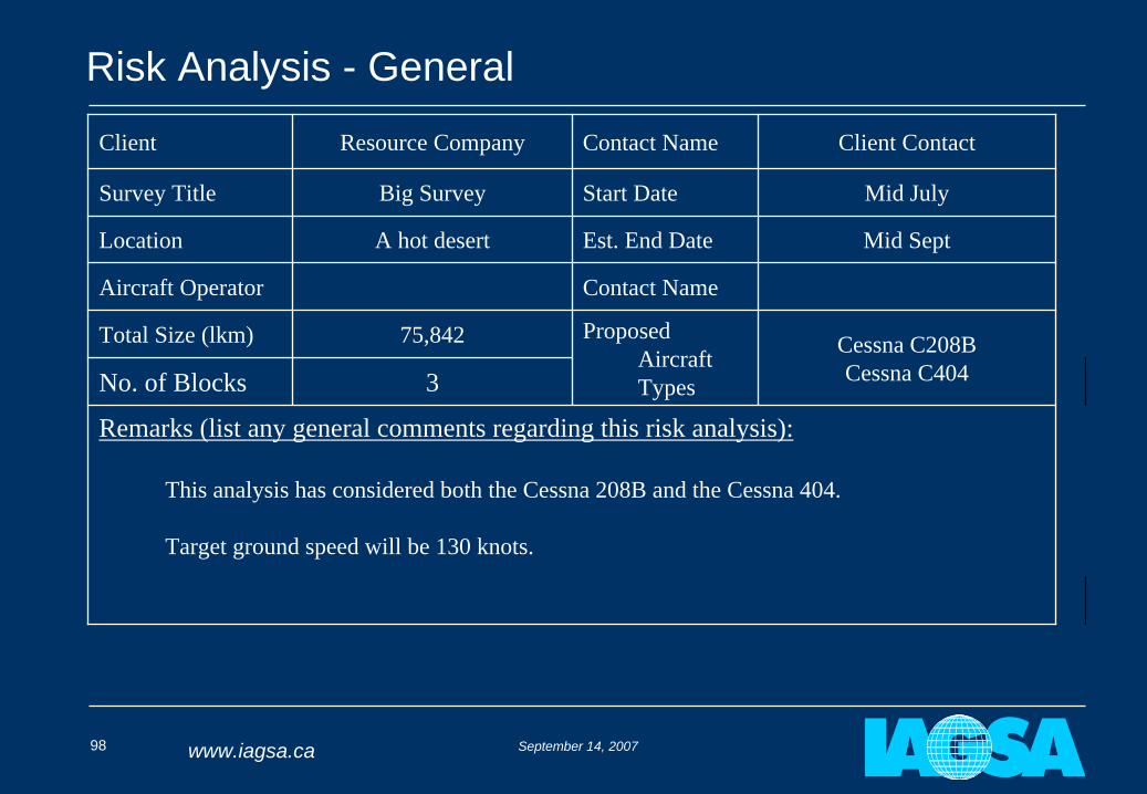
Risk Analysis - General
Start by gathering all information relevant to the survey being analyzed (i.e. survey location, terrain, surface cover, line lengths, prevailing weather, etc.)
Specific data for each aircraft Type being analyzed must also be included
IAGSA form provides guidance on what information is required
September 14, 200798 www.iagsa.ca
Risk Analysis - General
Client Resource Company Contact Name Client Contact
Survey Title Big Survey Start Date Mid July
Location A hot desert Est. End Date Mid Sept
Aircraft Operator Contact Name
Total Size (lkm) 75,842 Proposed Aircraft Types
Cessna C208BCessna C404No. of Blocks 3
Remarks (list any general comments regarding this risk analysis):
This analysis has considered both the Cessna 208B and the Cessna 404.
Target ground speed will be 130 knots.
September 14, 200799 www.iagsa.ca
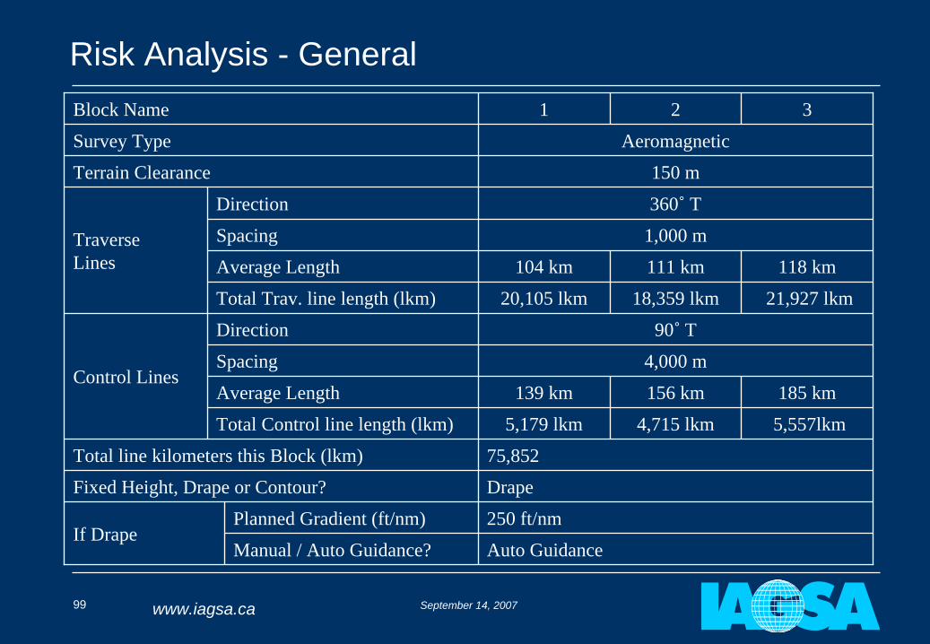
Risk Analysis - GeneralBlock Name 1 2 3
Survey Type Aeromagnetic
Terrain Clearance 150 m
TraverseLines
Direction 360˚
T
Spacing 1,000 m
Average Length 104 km 111 km 118 km
Total Trav. line length (lkm) 20,105 lkm 18,359 lkm 21,927 lkm
Control Lines
Direction 90˚
T
Spacing 4,000 m
Average Length 139 km 156 km 185 km
Total Control line length (lkm) 5,179 lkm 4,715 lkm 5,557lkm
Total line kilometers this Block (lkm) 75,852
Fixed Height, Drape or Contour? Drape
If DrapePlanned Gradient (ft/nm) 250 ft/nm
Manual / Auto Guidance? Auto Guidance
September 14, 2007100 www.iagsa.ca
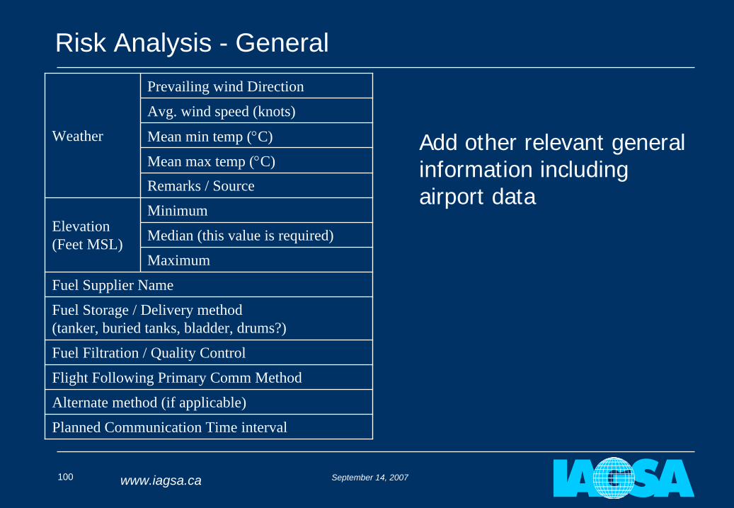
Risk Analysis - General
Weather
Prevailing wind Direction
Avg. wind speed (knots)
Mean min temp (C)
Mean max temp (C)Remarks / Source
Elevation (Feet MSL)
Minimum
Median (this value is required)
Maximum
Fuel Supplier Name
Fuel Storage / Delivery method(tanker, buried tanks, bladder, drums?)
Fuel Filtration / Quality Control
Flight Following Primary Comm Method
Alternate method (if applicable)
Planned Communication Time interval
Add other relevant general information including airport data
September 14, 2007101 www.iagsa.ca
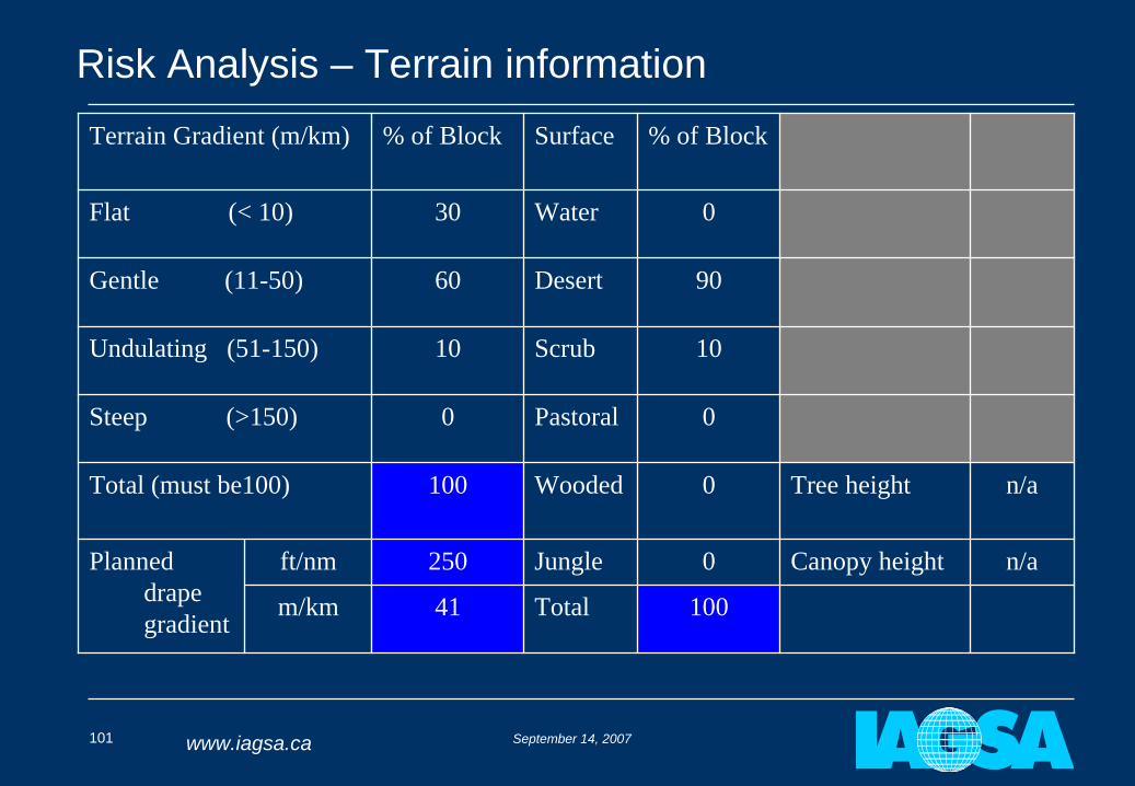
Risk Analysis – Terrain informationTerrain Gradient (m/km) % of Block Surface % of Block
Flat (< 10) 30 Water 0
Gentle (11-50) 60 Desert 90
Undulating (51-150) 10 Scrub 10
Steep (>150) 0 Pastoral 0
Total (must be100) 100 Wooded 0 Tree height n/a
Planned drape gradient
ft/nm 250 Jungle 0 Canopy height n/a
m/km 41 Total 100
September 14, 2007102 www.iagsa.ca
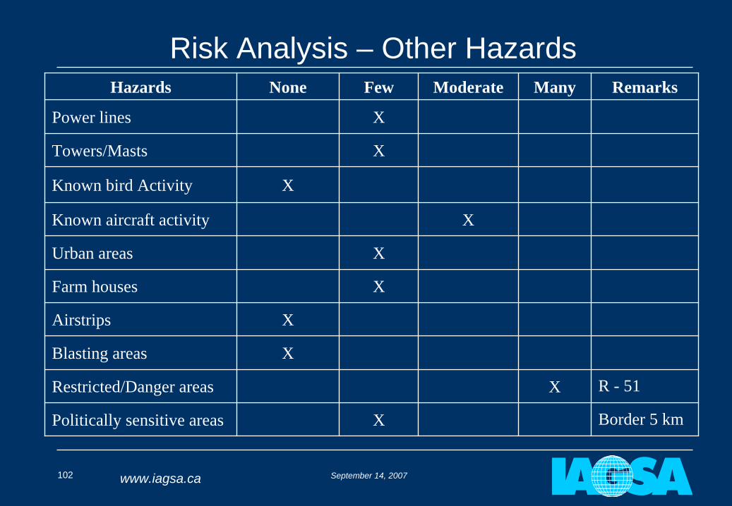
Risk Analysis – Other HazardsHazards None Few Moderate Many Remarks
Power lines X
Towers/Masts X
Known bird Activity X
Known aircraft activity X
Urban areas X
Farm houses X
Airstrips X
Blasting areas X
Restricted/Danger areas X R - 51
Politically sensitive areas X Border 5 km
September 14, 2007103 www.iagsa.ca
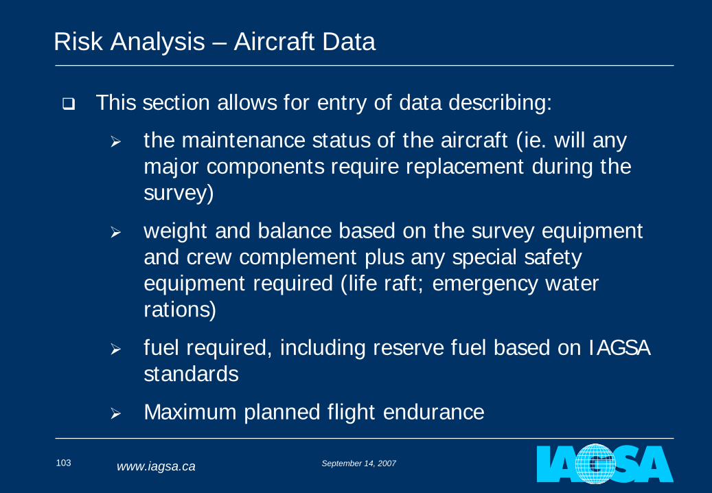
Risk Analysis – Aircraft Data
This section allows for entry of data describing:
the maintenance status of the aircraft (ie. will any major components require replacement during the survey)
weight and balance based on the survey equipment and crew complement plus any special safety equipment required (life raft; emergency water rations)
fuel required, including reserve fuel based on IAGSA standards
Maximum planned flight endurance
September 14, 2007104 www.iagsa.ca
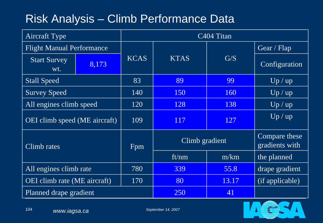
Risk Analysis – Climb Performance DataAircraft Type C404 TitanFlight Manual Performance
KCAS KTAS G/SGear / Flap
Start Survey wt. 8,173 Configuration
Stall Speed 83 89 99 Up / upSurvey Speed 140 150 160 Up / upAll engines climb speed 120 128 138 Up / up
OEI climb speed (ME aircraft) 109 117 127 Up / up
Climb rates FpmClimb gradient Compare these
gradients withft/nm m/km the planned
All engines climb rate 780 339 55.8 drape gradientOEI climb rate (ME aircraft) 170 80 13.17 (if applicable)Planned drape gradient 250 41
September 14, 2007105 www.iagsa.ca
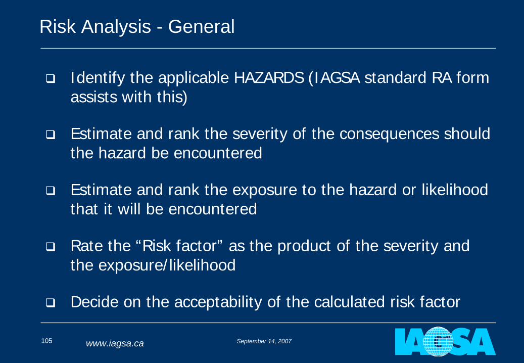
Risk Analysis - General
Identify the applicable HAZARDS (IAGSA standard RA form assists with this)
Estimate and rank the severity of the consequences should the hazard be encountered
Estimate and rank the exposure to the hazard or likelihood that it will be encountered
Rate the “Risk factor” as the product of the severity and the exposure/likelihood
Decide on the acceptability of the calculated risk factor
September 14, 2007106 www.iagsa.ca
Risk Analysis – One Engine Inoperative Risk Matrix
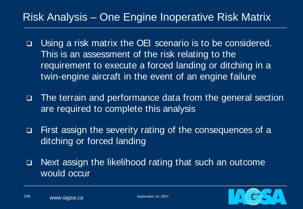
Using a risk matrix the OEI scenario is to be considered. This is an assessment of the risk relating to the requirement to execute a forced landing or ditching in a twin-engine aircraft in the event of an engine failure
The terrain and performance data from the general section are required to complete this analysis
First assign the severity rating of the consequences of a ditching or forced landing
Next assign the likelihood rating that such an outcome would occur
September 14, 2007107 www.iagsa.ca
Risk Analysis – One Engine Inoperative Risk Matrix
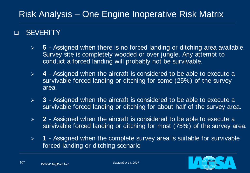
SEVERITY
5 - Assigned when there is no forced landing or ditching area available. Survey site is completely wooded or over jungle. Any attempt to conduct a forced landing will probably not be survivable.
4 - Assigned when the aircraft is considered to be able to execute a survivable forced landing or ditching for some (25%) of the survey area.
3 - Assigned when the aircraft is considered to be able to execute a survivable forced landing or ditching for about half of the survey area.
2 - Assigned when the aircraft is considered to be able to execute a survivable forced landing or ditching for most (75%) of the survey area.
1 - Assigned when the complete survey area is suitable for survivable forced landing or ditching scenario
September 14, 2007108 www.iagsa.ca
Risk Analysis – One Engine Inoperative Risk Matrix
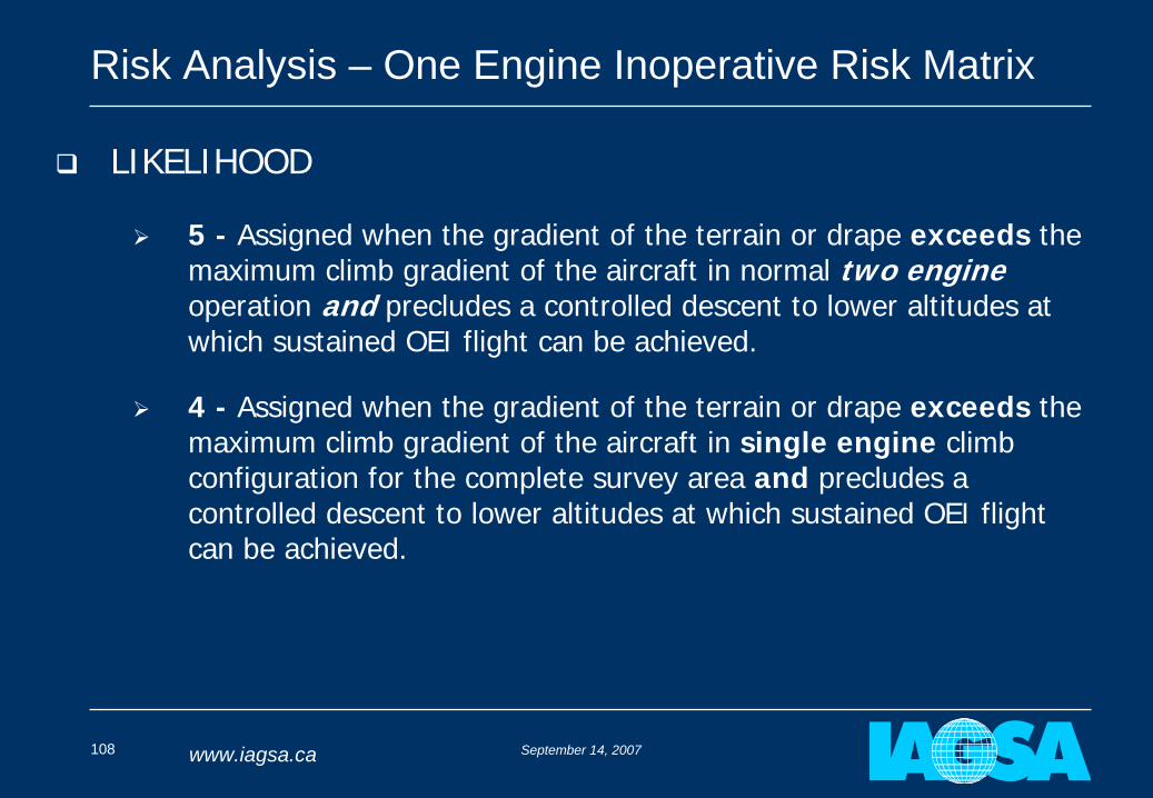
LIKELIHOOD
5 - Assigned when the gradient of the terrain or drape exceeds the maximum climb gradient of the aircraft in normal two engine operation and precludes a controlled descent to lower altitudes at which sustained OEI flight can be achieved.
4 - Assigned when the gradient of the terrain or drape exceeds the maximum climb gradient of the aircraft in single engine climb configuration for the complete survey area and precludes a controlled descent to lower altitudes at which sustained OEI flight can be achieved.
September 14, 2007109 www.iagsa.ca
Risk Analysis – One Engine Inoperative Risk Matrix
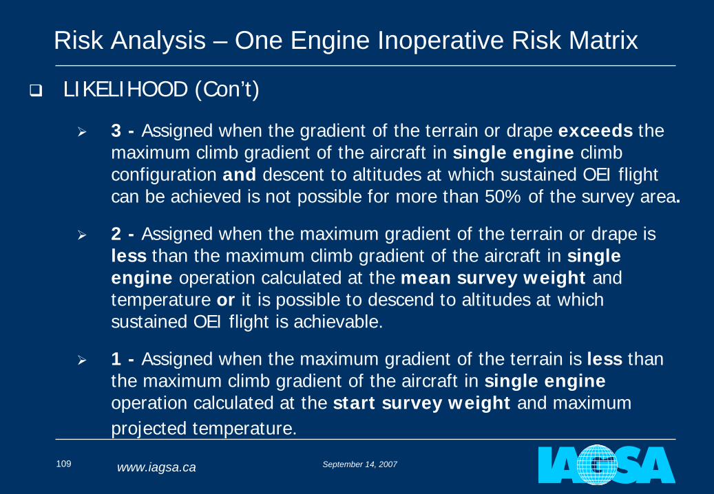
LIKELIHOOD (Con’t)
3 - Assigned when the gradient of the terrain or drape exceeds the maximum climb gradient of the aircraft in single engine climb configuration and descent to altitudes at which sustained OEI flight can be achieved is not possible for more than 50% of the survey area.
2 - Assigned when the maximum gradient of the terrain or drape is less than the maximum climb gradient of the aircraft in single engine operation calculated at the mean survey weight and temperature or it is possible to descend to altitudes at which sustained OEI flight is achievable.
1 - Assigned when the maximum gradient of the terrain is less than the maximum climb gradient of the aircraft in single engine operation calculated at the start survey weight and maximum projected temperature.
September 14, 2007110 www.iagsa.ca
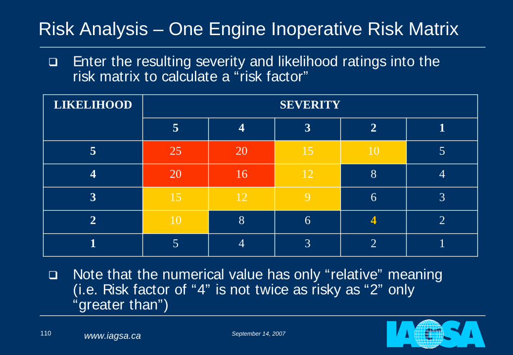
Risk Analysis – One Engine Inoperative Risk Matrix
Note that the numerical value has only “relative” meaning (i.e. Risk factor of “4” is not twice as risky as “2” only “greater than”)
LIKELIHOOD SEVERITY
5 4 3 2 1
5 25 20 15 10 5
4 20 16 12 8 4
3 15 12 9 6 3
2 10 8 6 4 2
1 5 4 3 2 1
Enter the resulting severity and likelihood ratings into the risk matrix to calculate a “risk factor”
September 14, 2007111 www.iagsa.ca
Risk Analysis - Use of The Risk Matrix
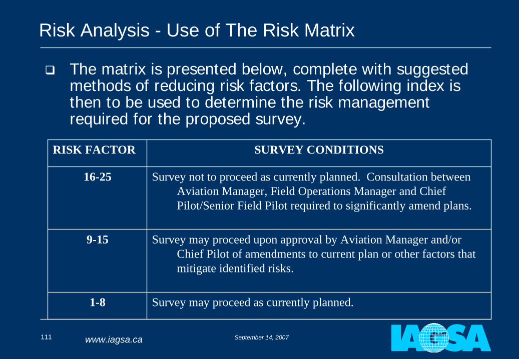
The matrix is presented below, complete with suggested methods of reducing risk factors. The following index is then to be used to determine the risk management required for the proposed survey.
RISK FACTOR SURVEY CONDITIONS
16-25 Survey not to proceed as currently planned. Consultation between Aviation Manager, Field Operations Manager and Chief Pilot/Senior Field Pilot required to significantly amend plans.
9-15 Survey may proceed upon approval by Aviation Manager and/or Chief Pilot of amendments to current plan or other factors that mitigate identified risks.
1-8 Survey may proceed as currently planned.
September 14, 2007112 www.iagsa.ca
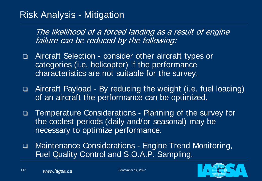
Risk Analysis - Mitigation
The likelihood of a forced landing as a result of engine failure can be reduced by the following:
Aircraft Selection - consider other aircraft types or categories (i.e. helicopter) if the performance characteristics are not suitable for the survey.
Aircraft Payload - By reducing the weight (i.e. fuel loading) of an aircraft the performance can be optimized.
Temperature Considerations - Planning of the survey for the coolest periods (daily and/or seasonal) may be necessary to optimize performance.
Maintenance Considerations - Engine Trend Monitoring, Fuel Quality Control and S.O.A.P. Sampling.
September 14, 2007113 www.iagsa.ca
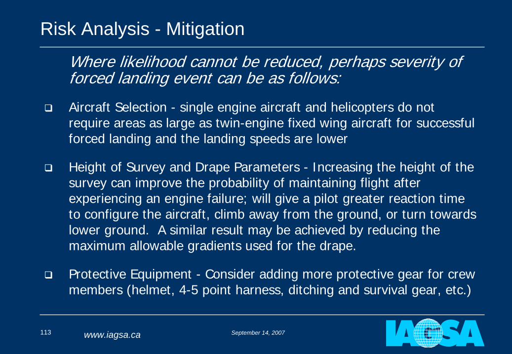
Risk Analysis - Mitigation
Where likelihood cannot be reduced, perhaps severity of forced landing event can be as follows:
Aircraft Selection - single engine aircraft and helicopters do not require areas as large as twin-engine fixed wing aircraft for successful forced landing and the landing speeds are lower
Height of Survey and Drape Parameters - Increasing the height of the survey can improve the probability of maintaining flight after experiencing an engine failure; will give a pilot greater reaction time to configure the aircraft, climb away from the ground, or turn towards lower ground. A similar result may be achieved by reducing the maximum allowable gradients used for the drape.
Protective Equipment - Consider adding more protective gear for crew members (helmet, 4-5 point harness, ditching and survival gear, etc.)
September 14, 2007114 www.iagsa.ca
Risk Analysis – Which Aircraft
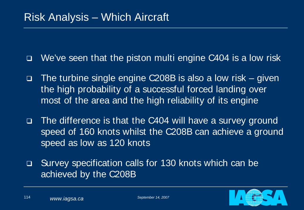
We’ve seen that the piston multi engine C404 is a low risk
The turbine single engine C208B is also a low risk – given the high probability of a successful forced landing over most of the area and the high reliability of its engine
The difference is that the C404 will have a survey ground speed of 160 knots whilst the C208B can achieve a ground speed as low as 120 knots
Survey specification calls for 130 knots which can be achieved by the C208B
September 14, 2007115 www.iagsa.ca
Risk Analysis – Helicopter
September 14, 2007116 www.iagsa.ca
Risk Analysis – Helicopter Autorotation Risk Matrix
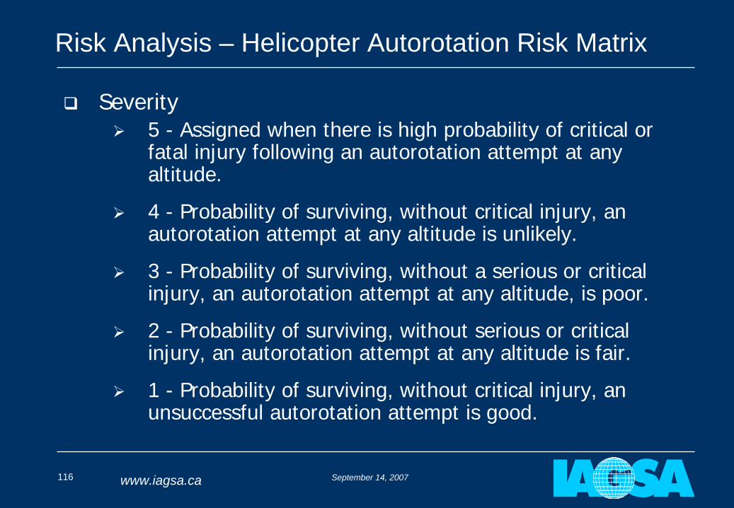
Severity
5 - Assigned when there is high probability of critical or fatal injury following an autorotation attempt at any altitude.
4 - Probability of surviving, without critical injury, an autorotation attempt at any altitude is unlikely.
3 - Probability of surviving, without a serious or critical injury, an autorotation attempt at any altitude, is poor.
2 - Probability of surviving, without serious or critical injury, an autorotation attempt at any altitude is fair.
1 - Probability of surviving, without critical injury, an unsuccessful autorotation attempt is good.
September 14, 2007117 www.iagsa.ca
Risk Analysis – Helicopter Autorotation Risk Matrix
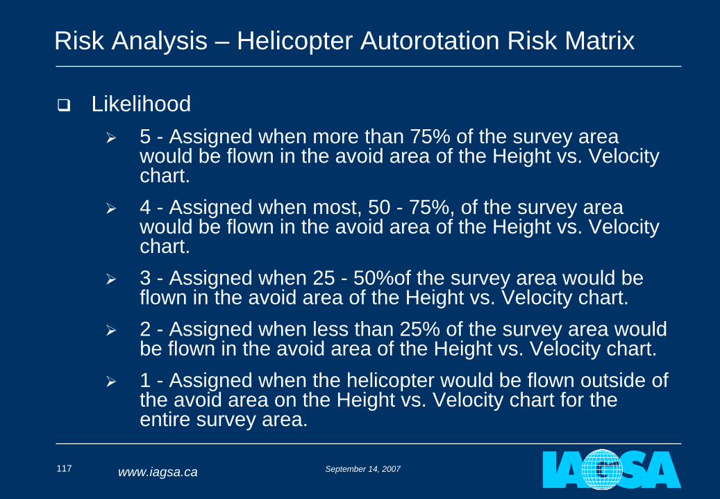
Likelihood
5 - Assigned when more than 75% of the survey area would be flown in the avoid area of the Height vs. Velocity chart.
4 - Assigned when most, 50 - 75%, of the survey area would be flown in the avoid area of the Height vs. Velocity chart.
3 - Assigned when 25 - 50%of the survey area would be flown in the avoid area of the Height vs. Velocity chart.
2 - Assigned when less than 25% of the survey area would be flown in the avoid area of the Height vs. Velocity chart.
1 - Assigned when the helicopter would be flown outside of the avoid area on the Height vs. Velocity chart for the entire survey area.
September 14, 2007118 www.iagsa.ca
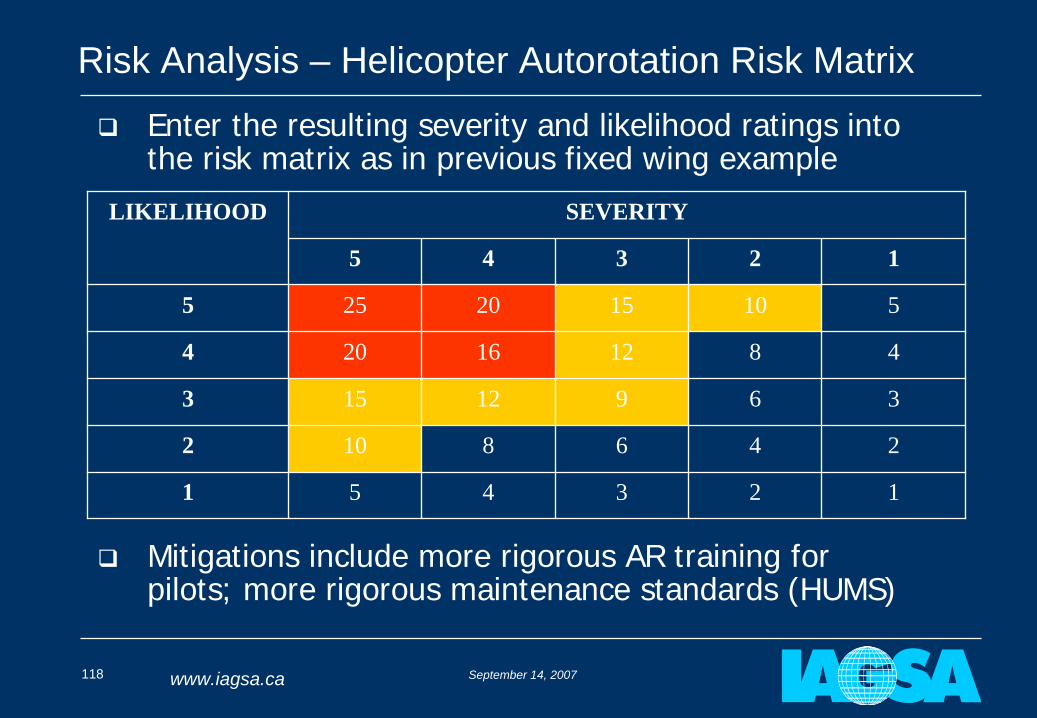
Risk Analysis – Helicopter Autorotation Risk Matrix
Mitigations include more rigorous AR training for pilots; more rigorous maintenance standards (HUMS)
LIKELIHOOD SEVERITY
5 4 3 2 1
5 25 20 15 10 5
4 20 16 12 8 4
3 15 12 9 6 3
2 10 8 6 4 2
1 5 4 3 2 1
Enter the resulting severity and likelihood ratings into the risk matrix as in previous fixed wing example
September 14, 2007119 www.iagsa.ca
Risk Analysis – Helicopter Risk Matrices
Other Risk matrices for:
HOGE performance
Hazards of executing a forced landing with power (due to weather or other factors)
For airplanes and helicopters also consider hazards that are independent of aircraft class and number of engines
September 14, 2007120 www.iagsa.ca
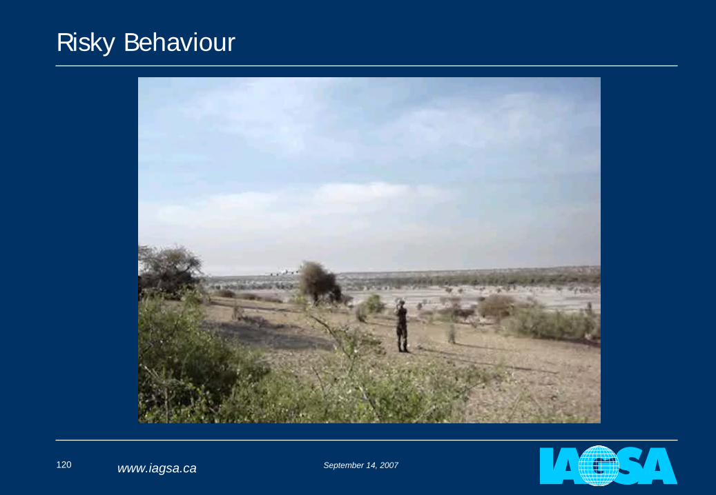
Risky Behaviour
September 14, 2007121 www.iagsa.ca
End of Part 6:
Sample Survey Flight Specifications and
Typical Risk Analyses
QUESTIONS?
September 14, 2007122 www.iagsa.ca
Part 7:
Accident Case Studies
Stan Medved
September 14, 2007123 www.iagsa.ca
Survey Accident Case Studies
Two survey accidents will be examined and how planning and appropriate controls may have prevented them:
May 1997, Cessna 210N – Emerald, Australia
November 1994, Aero Commander 680F – Cloncurry, Australia
September 14, 2007124 www.iagsa.ca
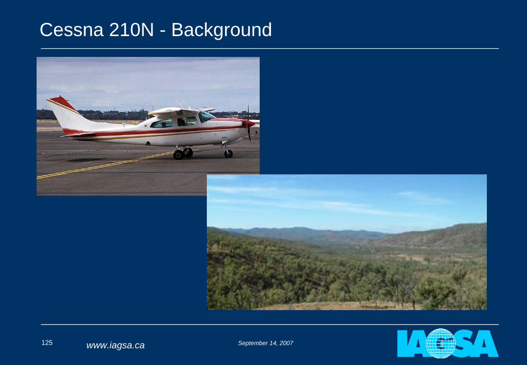
Cessna 210N - Background
Single engine Cessna 210N conducting survey west of Emerald, Australia in the Drummond Range area
One pilot and one operator on board
Planned height of 80m
East – West lines
Early morning departure for an expected ~ 5 hour flight
Generally open flat terrain except crossing Drummond Range (400m above surrounding terrain) with a number of narrow valleys
One line over rugged terrain needed to be reflown
September 14, 2007125 www.iagsa.ca
Cessna 210N - Background
September 14, 2007126 www.iagsa.ca
Cessna 210N - Background
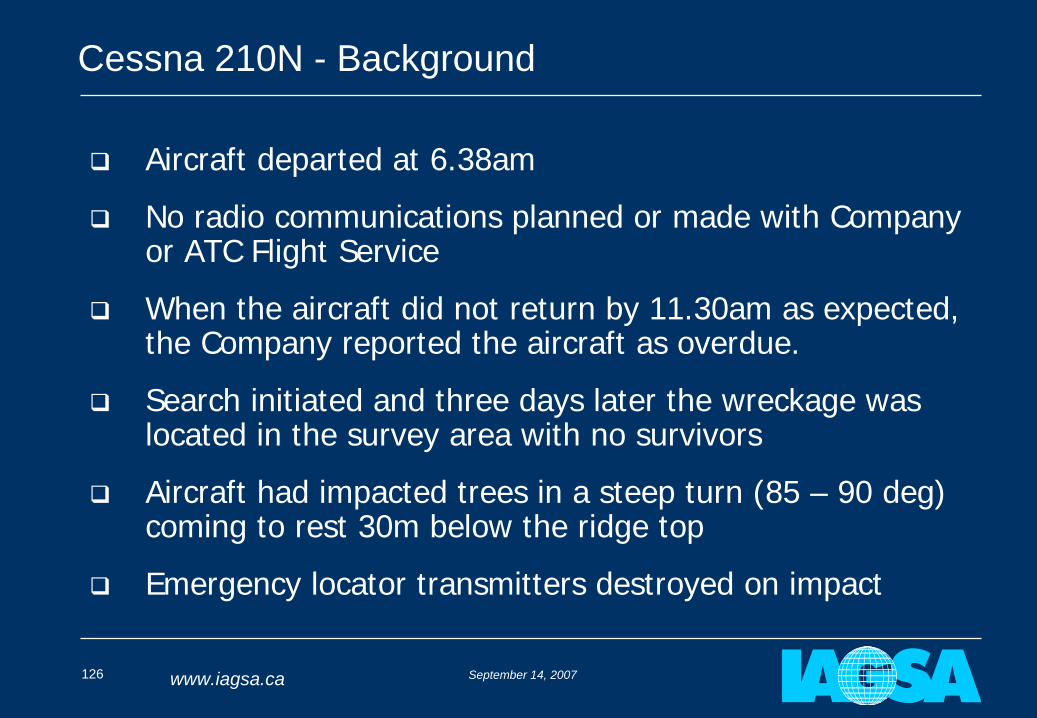
Aircraft departed at 6.38am
No radio communications planned or made with Company or ATC Flight Service
When the aircraft did not return by 11.30am as expected, the Company reported the aircraft as overdue.
Search initiated and three days later the wreckage was located in the survey area with no survivors
Aircraft had impacted trees in a steep turn (85 – 90 deg) coming to rest 30m below the ridge top
Emergency locator transmitters destroyed on impact
September 14, 2007127 www.iagsa.ca
Cessna 210N - Conditions
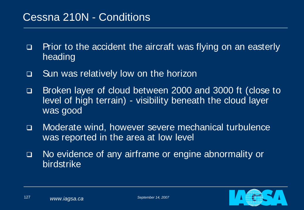
Prior to the accident the aircraft was flying on an easterly heading
Sun was relatively low on the horizon
Broken layer of cloud between 2000 and 3000 ft (close to level of high terrain) - visibility beneath the cloud layer was good
Moderate wind, however severe mechanical turbulence was reported in the area at low level
No evidence of any airframe or engine abnormality or birdstrike
September 14, 2007128 www.iagsa.ca
Cessna 210N - Conditions
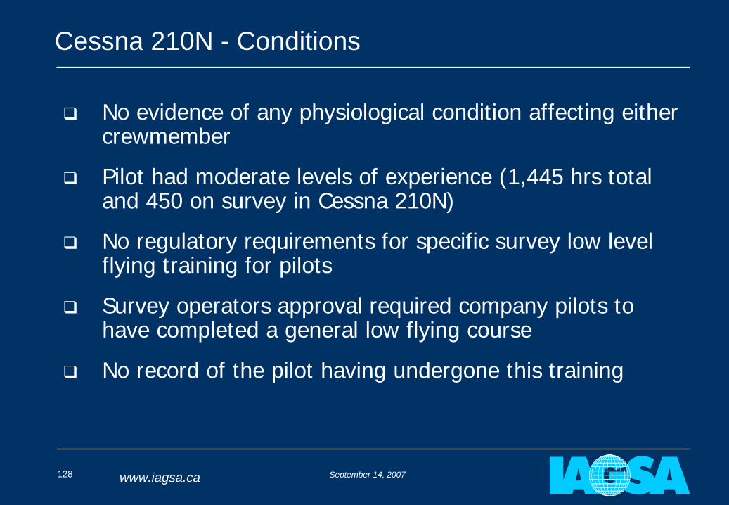
No evidence of any physiological condition affecting either crewmember
Pilot had moderate levels of experience (1,445 hrs total and 450 on survey in Cessna 210N)
No regulatory requirements for specific survey low level flying training for pilots
Survey operators approval required company pilots to have completed a general low flying course
No record of the pilot having undergone this training
September 14, 2007129 www.iagsa.ca
Cessna 210N - Conditions
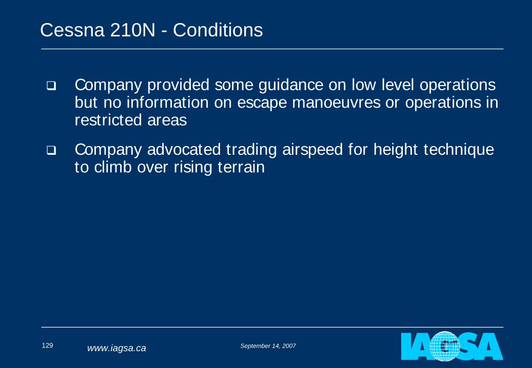
Company provided some guidance on low level operations but no information on escape manoeuvres or operations in restricted areas
Company advocated trading airspeed for height technique to climb over rising terrain
September 14, 2007130 www.iagsa.ca
Cessna 210N - Findings
Wind conditions were conducive to severe mechanical turbulence
Data quality in the accident area was poor the previous day flown in similar conditions
Sun glare and cloud may have affected pilot’s visibility
Pilot had not received appropriate low flying training for the environment
Company guidance was inadequate for the operating environment
Failure of ELTs resulted in a very large search area
September 14, 2007131 www.iagsa.ca
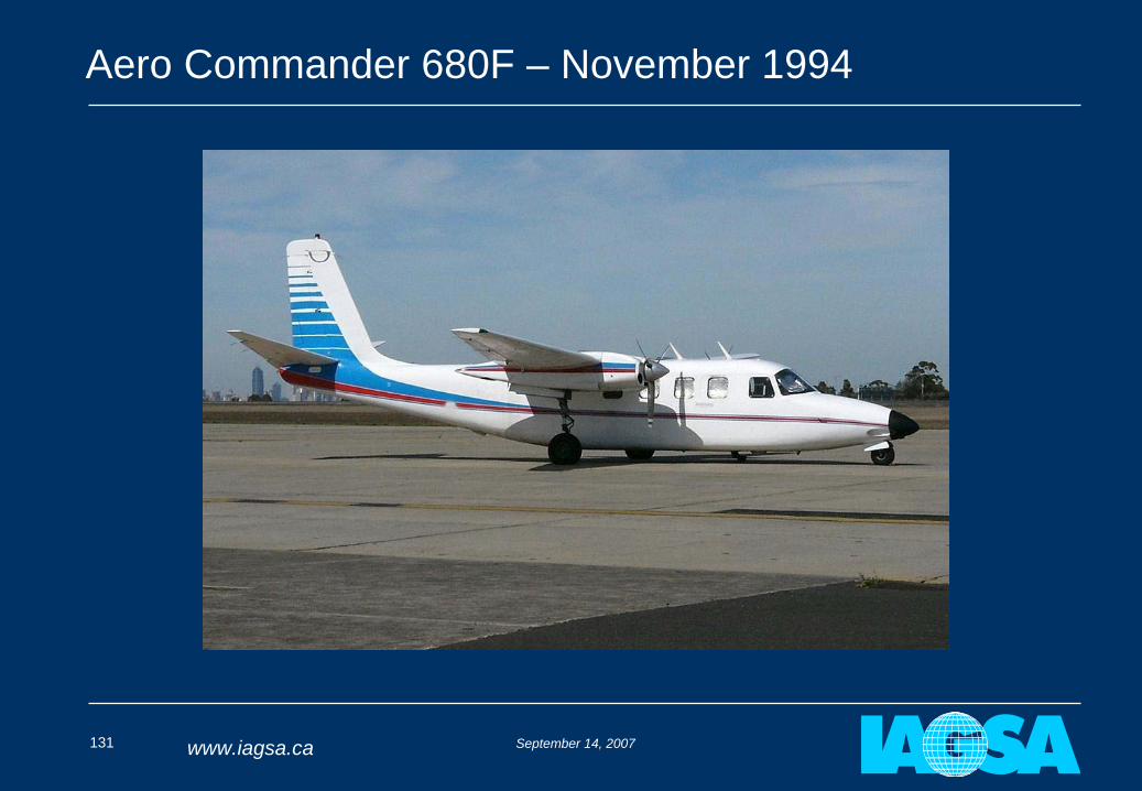
Aero Commander 680F – November 1994
September 14, 2007132 www.iagsa.ca
Aero Commander 680F - Background
Aeromagnetic survey, 80m height, 140 knots, ~ 5hr duration
Aircraft departed between 7.00 and 7.30am with pilot and operator on board
No radio communications planned or made with Company or ATC Flight Service
When the aircraft did not return by 12.30pm as expected, a field crew member started making calls to see if the aircraft had landed elsewhere
Formal SAR action initiated at 8.45pm
September 14, 2007133 www.iagsa.ca
Aero Commander 680F - Conditions
Aircraft wreckage found next morning
Aircraft was 3.4% above maximum takeoff weight
Calculated best single engine rate of climb was 160 ft/min
Weather conditions were good – clear skies and light winds, 37C
Aircraft was out of control at impact (120 deg bank and 35 deg nose down)
At time of impact right engine was operating at full power, left engine shutdown and propeller feathered
September 14, 2007134 www.iagsa.ca
Aero Commander 680F - Conditions
No mechanical abnormalities in airframe, both engines and propellers
Left engine fuel selector valve: Centre and Outboard tanks in closed position
Right engine fuel selector valve: Centre tank open; Outboard tank closed
September 14, 2007135 www.iagsa.ca
Aero Commander 680F - Pilot
Pilot was experienced in survey operations
Pilot had 710 hours in Aero Commander 500 series aircraft but had only flown the 680F model once, the day before and had not flown any other Aero Commander series aircraft in the preceding four months
Pilot had received a verbal briefing from another company pilot on the differences in the fuel system between the 500 series and 680F Aero Commander models
Pilot had left the hotel at 5.00am and did not have breakfast
September 14, 2007136 www.iagsa.ca
Aero Commander 680F – Fuel System
The Aero Commander’s fuel system has a number of fuel tanks that need to be manually selected and managed
Attention is needed to ensure that as the outboard tank gets close to empty the centre tank is selected before the engine is starved of fuel
Company pilots used different procedures for managing fuel usage
The fuel tanks, fuel usage rates and fuel selector panel differ between the 500 series and 680F
The outboard tanks empty in ~60 minutes in the 500 series and ~20 minutes in the 680F (left tank 3 – 5 minutes quicker than the right tank)
September 14, 2007137 www.iagsa.ca
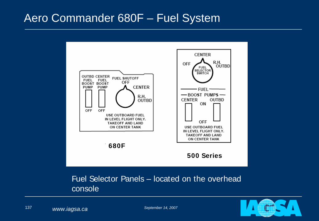
Aero Commander 680F – Fuel System
Fuel Selector Panels – located on the overhead console
680F500 Series
September 14, 2007138 www.iagsa.ca
Aero Commander 680F – Hypothesis
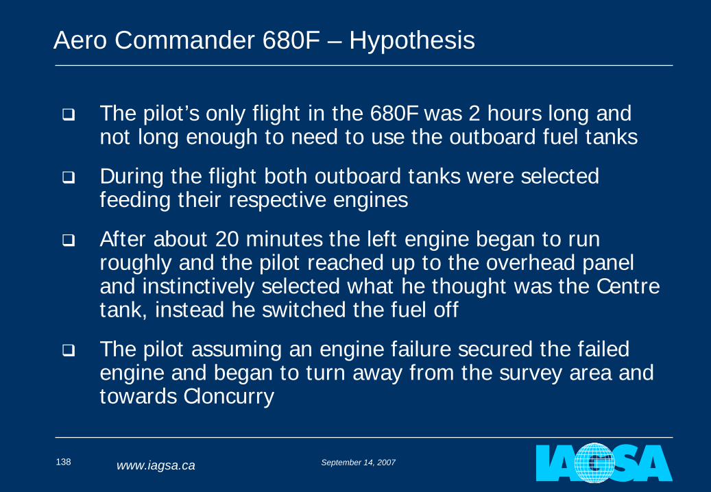
The pilot’s only flight in the 680F was 2 hours long and not long enough to need to use the outboard fuel tanks
During the flight both outboard tanks were selected feeding their respective engines
After about 20 minutes the left engine began to run roughly and the pilot reached up to the overhead panel and instinctively selected what he thought was the Centre tank, instead he switched the fuel off
The pilot assuming an engine failure secured the failed engine and began to turn away from the survey area and towards Cloncurry
September 14, 2007139 www.iagsa.ca
Aero Commander 680F – Hypothesis
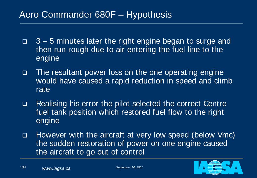
3 – 5 minutes later the right engine began to surge and then run rough due to air entering the fuel line to the engine
The resultant power loss on the one operating engine would have caused a rapid reduction in speed and climb rate
Realising his error the pilot selected the correct Centre fuel tank position which restored fuel flow to the right engine
However with the aircraft at very low speed (below Vmc) the sudden restoration of power on one engine caused the aircraft to go out of control
September 14, 2007140 www.iagsa.ca
Aero Commander 680F – Findings
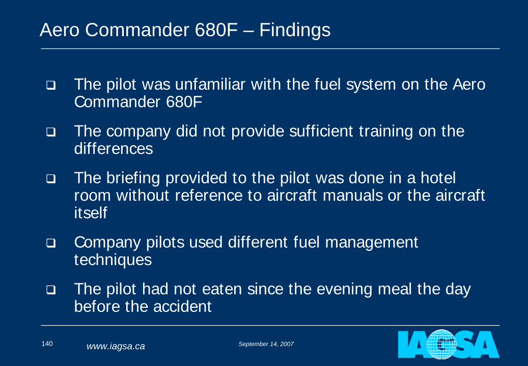
The pilot was unfamiliar with the fuel system on the Aero Commander 680F
The company did not provide sufficient training on the differences
The briefing provided to the pilot was done in a hotel room without reference to aircraft manuals or the aircraft itself
Company pilots used different fuel management techniques
The pilot had not eaten since the evening meal the day before the accident
September 14, 2007141 www.iagsa.ca
Aero Commander 680F – Findings
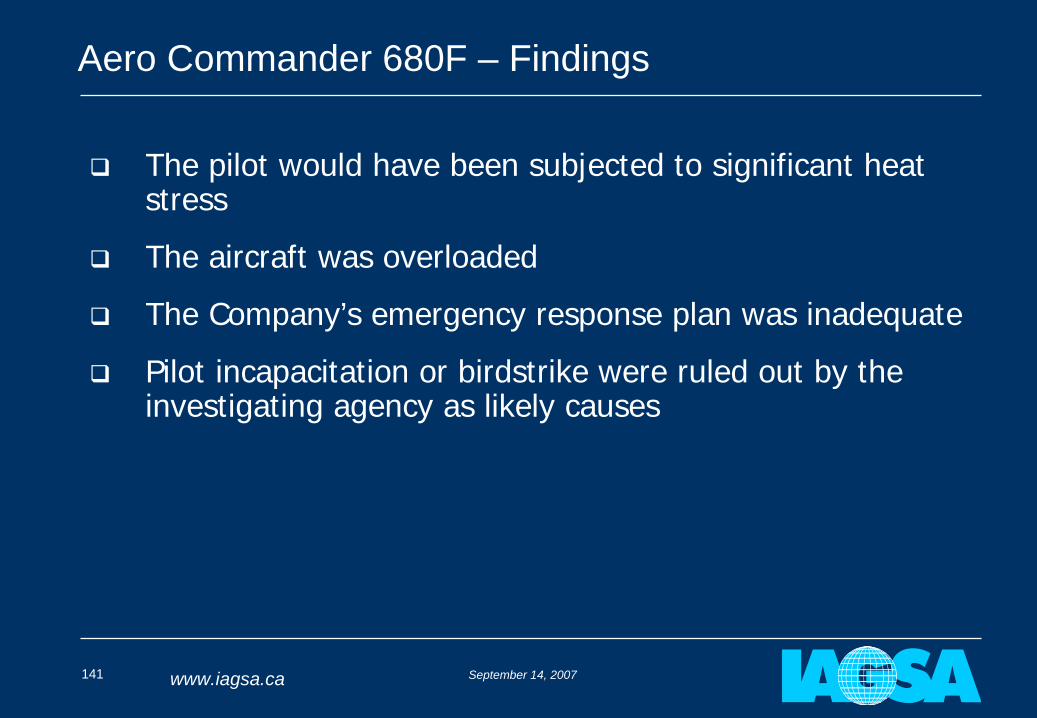
The pilot would have been subjected to significant heat stress
The aircraft was overloaded
The Company’s emergency response plan was inadequate
Pilot incapacitation or birdstrike were ruled out by the investigating agency as likely causes
September 14, 2007142 www.iagsa.ca
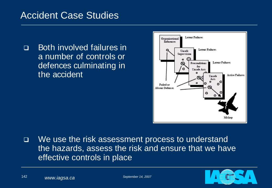
Accident Case Studies
Both involved failures in a number of controls or defences culminating in the accident
We use the risk assessment process to understand the hazards, assess the risk and ensure that we have effective controls in place
September 14, 2007143 www.iagsa.ca
Part 8:
Conclusions
Stan Medved & John Issenman
September 14, 2007144 www.iagsa.ca
Conclusions
Airborne geophysical survey is a relatively high risk activity
The nature of the activity provides little margin
Through detailed planning and understanding of the risks and controls available we can make it as safe as routine charter flying
It takes a cooperative approach involving both the survey provider and client commissioning the surveys
The controls developed and implemented have proven to be effective
Whilst these risk controls increase cost they also allow surveys to be carried out more efficiently
September 14, 2007145 www.iagsa.ca
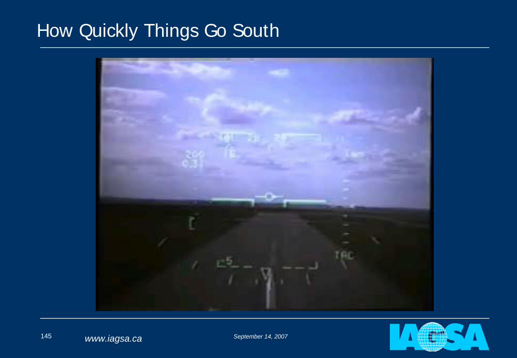
How Quickly Things Go South
September 14, 2007146 www.iagsa.ca
Exploration 07
More information at:
www.iagsa.ca
Questions?