airborne express gov-01-55-04
TRANSCRIPT

Nuclear Fuel Services, Inc.P.O. Box 337. MS 123Erwin, rN37650
(423) 743-9141
E-Mall :http://ww1WWatnfs-com
AIRBORNE EXPRESS 21 G-03-0277GOV-01-55-04
ACF-03-0363
October 23, 2003
DirectorOffice of Nuclear Material Safety and SafeguardsU.S. Nuclear Regulatory CommissionAttention: Document Control DeskWashington, DC 20555
References:
Subject:
1) Docket No. 70-143; SNM License 1242) Letter from B.M. Moore to NRC, Licensing Plan of Action to Support the
Blended Low-Enriched Uranium Project at Nuclear Fuel Services, datedOctober4,2001 (21G-01-0180)
3) Letter from NRC to B.M. Moore, Nuclear Fuel Services, Inc., Amendment 31(TAC No. L31535) to Approve Integrated Safety Analysis Plan and DeleteLicense Conditions S-28 through S-38, dated October 30, 2001
4) Letter from B.M. Moore, Supplemental Environmental Report for LicensingActions to Support the BLEU Project, dated November 9, 2001 (21G-01-0261)
5) Federal Register, Environmental Assessment and Finding of No SignificantImpact of License Amendment for Nuclear Fuel Services, Inc., (Vol. 67,No. 131, pp. 45555-45558), issued July 9, 2002
License Amendment Request for the Oxide Conversion Buildingand Effluent Processing Building at the BLEU Complex
Dear Sir:
Nuclear Fuel Services, Inc. (NFS) hereby requests an amendment to the referenced license toauthorize processing of special nuclear materials in the Oxide Conversion Building (OCB) andthe Effluent Processing Building (EPB) at the BLEU Complex. The request contained herein isthe last of three license amendment applications needed to support operations involving theconversion of low-enriched uranium materials into oxides and treatment of process effluents insupport of the Blended Low-Enriched Uranium (BLEU) Project, as described in Reference 2.
Page changes to Parts I and II of the referenced license are contained in Attachment I. Changesto portions of the referenced license concerning NES' organization and administration, nuclearcriticality safety program, decommissioning activities and emergency preparedness were not
I

B.M. Moore to Dir., NMSS 21G-03-0277Page 2 GOV-01-55-04October 23, 2002 ACF-03-0363
required.
A summary of the proposed changes to License SNM-124 follows:
Chapter 5 - Environmental Protection: Revisions to this chapter were necessary to describesampling and methods to assess sampling results of liquid effluents that will be discharged fromthe BLEU Complex to the City of Erwin - Publicly Owned Treatment Works (POTW).
Chapter 9. Section A - General Information: Minor changes were required to add the OCB(Bldg. 520) and EPB (Bldg. 530) to Figure 9.2 Plant Layout and Property Boundaries.
Chapter 10, Section A - Site Layout: Minor changes were required to add the OCB (Bldg. 520)and EPB (Bldg. 530) to Figure 10.1 Plant Layout with Building Descriptions.
Chapter 10, Section B - Utilities: This section was revised to convey the types of utilities thatwould be used to supply electricity, emergency power, compressed air, and water supply to theOCB and EPB.
Chapter 10, Section C - Ventilation Systems: Minor changes to this section were included todocument the flow rates for the HVAC systems installed at the OCB and EPB.
Chapter 10, Section G - Ventilation - BLEU Complex: This section was revised to referencethe Integrated Safety Analysis (ISA) Summary for more detailed safety related informationpertaining to the ventilation systems at the OCB and EPB.
Chapter 10, Section H - Waste: Revisions to Figure 10.12 N.F.S. Inputs to the Sanitary WasteStream were necessary to illustrate the inputs and sampling point for discharges to the sanitarysewer at the BLEU Complex.
Chapter 10, Section I - Fire: Minor changes were necessary to reflect fire protectionequipment, systems, and measures that will be employed at the OCB and EPB.
Chapter 12, Section B - Instrumentation: A minor change was required to Figure 12.1Criticality Detector Locations reflecting the placement of nuclear criticality detectors at the OCBand EPB.
Chapter 12, Section E- Exposure Control: Revisions to Figure 12.2 Plant Areas Designatedwere necessary to reflect the locations of radiological controlled areas at the BLEU Complex.
Chapter 13. Section A - Environmental Protection: This section was revised to reflect newair emission sources that will be located at the OCB and EPB. Additionally, Section 13.3.2 wasrevised to describe sampling of sanitary waste streams that will be discharged from the BLEUComplex to the POTW.
Chapter 15. Section 14- Oxide Conversion Building- Building 520: A new section was

B.M. Moore to Dir., NMSS 21 G-03-0277Page 3 GOV-01-55-04October 23, 2002 ACF-03-0363
added that provides a general description of the process that will be used at the OCB. A moredetailed description is provided in the ISA Summary.
Chapter 15, Section 15 - Effluent Processing Building - Building 530: A new section wasadded that describes the process that will be used to treat process effluents at the EPB. A moredetailed description is provided in the ISA Summary.
The Safety and Safeguards Review Council has reviewed and approved these changes. For yourconvenience, vertical lines in the right-hand margin of affected license pages denote changes.
As required under Title 10, Code of Federal Regulations (CFR), Part 70.61, the contents of thelicense amendment application includes an ISA Summary (Attachment II) that was prepared in amanner consistent with Reference 3. The ISA Summary is considered proprietary information, asset forth in the enclosed affidavit; therefore, NFS requests that this information be withheld frompublic disclosure. A non-proprietary version of this ISA Summary suitable for public disclosurewill be submitted by Nober14034
A decommissioning cost estimate is included (Attachment m) for the OCB and EPB, as requiredunder Chapter 7.2.3 of the referenced license. As discussed with your staff, NFS will institute afinancial assurance instrument specified in 10 CFR 70.25(f), once the amount of financialassurance funding is deemed acceptable by the Nuclear Regulatory Commission (NRC) and priorto possessing SNM at the OCB and EPB. The decommissioning financial assurance costestimate is considered proprietary information, as set forth in the enclosed affidavit; therefore,NFS requests that this information be withheld from public disclosure.
The drawings enclosed herewith have the following statement affixed:
"This drawing and all information contained thereon is the property of NuclearFuel Services, Inc. and shall not be used or disclosed for any purpose other thanthat for which it has been furnished without the express written consent of NFS. "
Notwithstanding the language of this restriction, NFS acknowledges that reproduction andcontrolled distribution of submitted documents, in accordance with NRC regulations andrequirements, is necessary in order for the NRC to carry out its legal and regulatoryresponsibilities. Further, NFS acknowledges that reproduction and controlled distribution ofthese drawings by a third party authorized by the NRC is allowable by this language. Therefore,it is NFS' position that the enclosed drawings may be reproduced and distributed in a controlledmanner, by a third party authorized by the NRC, for NRC's purposes and use without violation ofthe statement above.
A Supplemental Environmental Report (Reference 4) supporting the OCB and EPB operationshas been reviewed by the NRC. The NRC issued an Environmental Assessment and Finding ofNo Significant Impact (EA/FONSI) for the BLEU Project (Reference 5). Since NFS previouslysubmitted information to support the NRC's environmental review of the entire BLEU Project,no additional information is contained herein.

B.M. Moore to Dir., NMSS 21 G-03-0277Page 4 GOV-01-55-04October 23, 2002 ACF-03-0363
To streamline the licensing process, NFS will submit the following additional information to theNRC under separate cover letters:
* Revisions to the Physical Security Plan for SNM (24Y-03-0030)* Revisions to the Fundamental Nuclear Material Control Plan (30G-03-2023)* Proposed Revisions to the NFS Emergency Plan (21G-03-0281)
NES requests the license amendment be issued by July 1, 2004 to support our project milestonesas previously discussed with the NRC. NFS appreciates the efforts of your staff in supporting thelicensing of this very important project.
If you or your staff have any questions, require additional information, or wish to discuss this,please contact me, or Mr. Rik Droke, Licensing and Compliance Director at (423) 743-1741.Please reference our unique document identification number (21G-03-0277) in anycorrespondence concerning this letter.
Sincerely,
NUCLEAR FUEL SERVICES, INC.
R)/7) axe~ OCr)OB. Marie MooreVice PresidentSafety and Regulatory
JSKICsnAttachmentcc:Regional Administrator Mr. Daniel RichU.S. Nuclear Regulatory Commission Senior Resident InspectorRegion II U.S. Nuclear Regulatory CommissionAtlanta Federal Center61 Forsyth Street, SWSuite 23T85Atlanta, GA 30303
Mr. William GloersenProject InspectorU.S. Nuclear Regulatory ConmnissionRegion IIAtlanta Federal Center61 Forsyth Street, SWSuite 23T85Atlanta, GA 30303

B.M. Moore to Dir., NMSSPage 5October 23, 2002
21G-03-0277GOV-01-55-04
ACF-03-0363
ENCLOSURE
AFFIDAVIT
1, B.M. Moore, Vice President of Safety and Regulatory at Nuclear Fuel Services, Inc. (NFS), make the followingrepresentations that to the best of my knowledge and beliefs:
I. The following documents which Nuclear Fuel Services, Inc. (NFS) wishes to have withheld from publicdisclosure, are:
Attachments I and IHI to NFS letter B. M. Moore toDirector, NMSS, dated October 23, 2003 (21G-03-0277), intheir entirety.
2. The information contained in the documents cited in I above has been held in confidence byNuclear Fuel Services, Inc. (NFS) in that it is of a privileged and confidential commercial nature.
3. The information contained in the documents cited in I above is the intellectual property of NuclearFuel Services, Inc. (NFS) and as such is customarily held in confidence by Nuclear Fuel Services,Inc. (NFS) or its contractor. Nuclear Fuel Services, Inc. (NFS) has customarily submittedprivileged and confidential information of this type to the Nuclear Regulatory Commission (NRC)and to its predecessor, the Atomic Energy Commnission (AEC), in confidence.
4. The information contained in the documents cited in I above has not been made available to publicsources by Nuclear Fuel Services, Inc. (NFS), nor has Nuclear Fuel Services, Inc. (NFS)authorized that it be made available.
5. The public disclosure of the information contained in the documents cited in I above is likely tocause substantial economic harm to Nuclear Fuel Services, Inc. (NFS).
B. Marie MooreVice PresidentSafety and Regulatory
1Q/ zD7atDate
I certify the above named person appeared before me and executed thisdocument on this theav dayf October, 2003.
'6 aryfPublic d / My commission expires. 021/D c 3

B.M. Moore to Dir., NMSS 21 G-03-0277Page 6 GOV-01-55-04October 23, 2002 ACF-03-0363
ENCLOSURE
AFFIDAVIT
1, John M. Flaherty, Plant Manager BLEU Complex at Framatome ANP, Inc. (FANP),make the following representations that to the best of my knowledge and beliefs:
1. The following documents which Framatome ANP, Inc. (FANP) wishes tohave withheld from public disclosure, are:
Attachment II and III to Nuclear Fuel Services, Inca letter B. M. Moore toDirector, NMSS, dated October 23, 2003 (21G-03-02 77), in their entirety.
2 The information contained in the documents cited in 1 above has been held inconfidence by FANP and are of a privileged, proprietary and confidentialcommercial nature.
3 The information contained in the documents cited in 1 above is the intellectualproperty of FANP and as such is customarily held in confidence by FANP orits contractor. FANP has customarily submitted privileged and confidentialinformation of this type to the Nuclear Regulatory Commission (NRC) and toits predecessor, the Atomic Energy Commission (AEC), in confidence.
4 The information contained in the documents cited in 1 above have not beenmade available to public sources by FANP, nor has FANP authorized that itbe made available.
5 The public disclosure of the information contained in the documents cited in Iabove is likely to cause substantial economic harm to FANP.
JoMl. Flahe rtt atPlant Manager, BLEU ComplexFramatome ANP, Inc.
I certify the above named person appeared before me and executed this document on thisthe day of October, 2003.
ary Public ~My Commission Expires

B.M. Moore to Dir., NMSS 21G-03-0277Page 7 GOV-01-55-04October 23, 2002 ACF-03-0363
Attachment IPage Changes to SNM-124
Part IPage Index
Pages 1 through 6
Chapter 5Page 2Page 8Page 9
Part IIPage Index
Pages 1 through 7Table of Contents
Pages i through viiiList of Figures
Pages ix through xii
Chapter 9. Section A. Pages 1-7Chapter 10. Section A. Pages 1-6Chapter 10. Section B. Pages 1-4Chapter 10, Section C. Pages 1-3Chapter 10. Section G. Pages 1-2Chanter 10. Section H. Pages 1-4Chapter I0. Section I. Pages 1-8Chapter 12. Section B. Pages 1-5Chapter 12, Section E. Pages 1-7
Chapter 13. Section A. Pages 1-10Chapter 15. Section 14. Pages 1-3Chapter 15. Section 15. Pages 1-2

SPECIAL NUCLEAR MATERIAL LICENSE
SNM-124
PAGE INDEX (Submitted)
(10/23/03)
Part Section Page(s) Revision Date
I Introduction
I Table of Contents
I List of Figures
iii
lI
iiiivv
viviivii-a
6
8
8
8
6
3
9
08/15/89
08/15/89
08/07/98
04/28/00
04/16/03
04/16/03
04/16/03
04/16/03
10/11/02viii
I List of Tables
I Chapter 1
I Appendix A
I Appendix B (NRC)
I Appendix C
I Appendix D
ix 3
1234S6789101112
6
7
.9
6
6
13
2
2
1
1
1
2
1234
1111
04/16/03
04/28/00
04/28/00
12/10/99
11/24/98
11/15/01
04/03/02
10/15/90
05/15/91
08/15/89
05/15/91
05/18/95
01/11/01
03/13/98
03/13/98
03/13/98
03/13/98
11/06/98
11/06/98
11/06/98
11/06/98
10/06/98
10/06/98
10/06/98
10/06/98
10/11/02
10/11/02
10/11/02
1234
000
0
1
234
0
000
12
3
l11
I

SPECIAL NUCLEAR MATERIAL LICENSE
SNM-124 (10/23/03)
PAGE INDEX (Submitted)
Part Section Page(s)8 Revision Date
I Chapter 2
I Chapter 3
1
2345
61789
10111213141516171819202122232425262728293031323334353637383940414243444546
09/1S/9809/15/9805/15/9108/15/8908/15/8903/13/9803/13/9803/13/9803/13/9810/15/9008/1S/8909/1S/9803/13/9803/13/9803/13/9807/30/9912/20/0012/20/0010/19/9810/19/9806/18/9307/30/9308/07/9210/15/90
10/15/9010/15/9011/16/9801/11/01
09/03/0309/03/0309/03/0304/16/03
09/03/0309/03/0304/16/0304/16/0304/16/0304/16/03
04/16/0304/16/0304/16/0304/16/0304/16/0304/16/03
04/16/03
04/16/03
05/15/91
09/03/0312
25
2

SPECIAL NUCLEAR MATERIAL LICENSE
SNM-124 (10/23/03) 1
PAGE INDEX (Submitted)
Part Section
I Chapter 3
I Chapter 4
Page (8) Revision
345
6789
10
11
12131415
16171819
202122232425
5
3
6
1
S
3
3
2
4
3
6
4
6
2
3
2
4
7
10
5
7
6
Date
03/13/98
05/18/95
03 113/98
08/15/89
03/13/98
05/18/95
05/18/95
05/15/91
05/20/92
05/18/95
01/23/03
03/13/98
12/10/99
05/18/95
05/15/91
05/19/91
12/10/99
01/23/03
01/23/03
04/28/00
04/28/00
04/28/00
03/13/98
10/23/98
10/23/98
10/23/98
10/23/98
10/23/98
10/23/98
10/23/98
10/23/9B
10/23/98
10/23/98
10/23/98
10/23/98
10/23/98
10/23/98
10/23/98
10/23/9810/23/98
10/23/98
10/23/98
10123/9810/23/98
10/23/98
10/23/98
10/23/98
10/23/98
2
3
4
6
7
8
9
10
11
12
13
14
15
16
17
18
19
20
21
22
23
24
25
3

SPECIAL NUCLEAR MATERIAL LICENSE
SNM-124
PAGE INDEX (Submitted)
(10/23/03) I
Part Section
I Chapter 4
I Chapter 5
Paqe (6) Revision
26
27
28
29
30
31
32
33
34
35
36
37
38
39
40
41
42
43
44
45
4647
48
49
50
51
52
53
54
5556
57
58
59
60
Date
10/23/98
10/23/98
10/23/98
05/21/99
05/21/99
10/23/98
10/23/98
10/23/98
10/23/98
10/23 /98
10/23/98
04/23/99
04/23/99
10/23/98
04/23/99
10/23/98
10/23/98
10/23/98
04/23/99
10/23/98
10/23/98
10/23/98
10/23/98
10/23/98
10/23/98
10/23/98
10/23/98
10/23/98
10/23/98
10/23/9810/23/98
10/23 /98
10/23/98
10/23/98
10/23/98
1
2
3
4
5
6
7
8
9
10
11
12
13
14
3
7
3
3
2
3
4
9
6
6
3
2
23
08/09/00
10/23/03
08/28/98
08/28/98
08/28/98
10/11/02
10/11/02
10/23/03
10/23/03
08/18/00
08/28/98
08/28/98
08/28/98
08/28/98
I
I
4

SPECIAL NUCLEAR MATERIAL LICENSE
SNM-124 (10/23/03) 1
PAGE INDEX (Submitted)
Part Section Page (s) Revision
I Chapter 5
I Chapter 6
I Chapter 7
I Chapter 7
Appendix A
I Chapter 7
Appendix B
I Chapter 8
15
16
17
18
19
20
21
22
23
32
3
8
5
2
2
2
0
1234
6
7
8
9
10
2
3
7
73
3
1
12
.1
Date
08/28/98
08/28/98
08/28/98
09/03/03
08/28/98
08/28/98
08/28/98
08/28/98
08/28/98
08/14/98
11/13/98
05/21/99
09/04/98
02/14/03
10/11/02
08/14/98
10/11/02
08/14/98
11/29/94
11/16/98
10/08/93
10/08/93
11/16/98
11/16/98
11/16/98
1234
56
8S
42
2
2
deleted
deleted
1 2 08/28/98
5

Table 5.1 Summary Table of Environmental Radiological Monitoring Program
Sampling Point Sample Type) Parameters Action Level Typical llDCCollection Analyzed (psCi/m unless (CUiimL tulessFrequency otherwise stated) otherwise stated)
Airborne Effluents'Operating Radiological Stacks'
Mdn Processing Stack Con rnuous/Ddily' Gross Alpha Cumulative> 16.5 mCill 2-months
Monthly Average > 2.02-11 8.OE-14= Gross Beta Cumulative > 3800 tnCill2-months
Monthly Average >4.7E-9 I.OE-13
Combined Releases fronm Contitnuous/Daiy Gross Alpha Curnulative > 1.8 mCi/12-months
_Other Urnium Stacks MonthlyAverage > 2.0E-12 8.OE-14_ Gross Beta Ouulsative > 270 rnCi/12-mmons
_ MonthlyAverage> 2.9E-10 1.0E-13Combiaed Releases from ContinuoussWeekly Gross Alpha Curnulative > 0.1 mCi/12-months _
Plutoniutn Stacks (Bldg. 234) Monthly Average> 7.0E-13 8.0E-15_ Gross Beta Cunnulative > 0.3 rnCU 12-months
_ _ Monthly Average > 1.9E-12 1.0E-14_ Amblent AIr ContintouslWeekly Gross Alpha QuarterlyAverage >S.OE-I5 3.0-15
_ Gross Beta Quarterly Average > 9.0E-11 .OE-14_ Compositt/Quarterly Isotopic U Total U > 5.OE-15 4.0E-16
_ Composite/Annually Isotopic Th Total Tb> 4.OE-16 I.OE-16
_ _ LsotopicPu Total Pu >2.0E-15 1.0L-16
L si d u Effluents .Surface Water
Banner Spring Branch Upstream Grab/Quarterly Gross Alpha Saple > 3.0E-8 .OE-08
_ tGross Beta Sample > 3.04-6 2.02-08
Martin Creek Upstream Grab/Quarterly Gross Alpha Sample > 3.0E- I.OE408
_ Gross Beta Sample > 3.0E26 2.04-08
Nolichuckey River Upstream GrablQuarterly Gross Alpha Sample > 3.0E-8_ 1.0-08
_ Gross Beta Sample > 3.0E-6 2.02408
_ Banner Spring Branch Downstream ContintuouslDaily' Gross Alpha Simple >3.0E-7 15E-08
_ Gross Beta SrnpIe >6.0E4 3.OE-08
CornposirteMonthly Isotopic U Sample SOF > 1.0 (see note 4) 1.00-09
Martin Creek Downstream GrabiVeekly Gross Alpha Sample > 3.02-7 1.5E-08
_ Gross Beta Sample > 6.0E4 3.0E408
Nolichuckey River Downstream GrahbQuartey Gross Alpha Sample > 3.0E-7 I S1-08
_Proces Waste Water
_Waste Water Treatinent Facility Grab/each batch Gross Alpha Batch>3E-7 1.5E-07
_ Gross Beta Batch > 6E-5 6.0E407
Composite/Monthly Isotopic U Sesniannual Average SOF > 1.0 (see notes 1.00-09__ 4 and 7)
_NFS Sanitar y Sewer Continuous/Daily' Gross Alpha SarPle > 3.02-7 1.5E-08
(See Note S) Gross Beta Sample > 6.0E4 3.02-08
CompositeMonthly Isotopic U Sample SOF > 0.5 (see note 4) .OE-09
Composite/Mothly9 Insoluble > insoluble gross alpha or beta alpha - 3.02-08Radioactivity radioactivity in backeround water beta - 5.0F.08
BLEU Complex Sanitary Sewer ContinuousDail? Gross Alpha Sample > 3.OE-7 1.5EOS_ GrosS Beta Sample > 6.0E-6 3.0E08
_ __ Cornposite/Monthly Isotopic U Sample SOF> 0.5 (tee note 4) 1.0E-09Composite/Monthly Insoluble > insoluble gross alpha or beta Alpha - 3.0E-08
Radioactivirv radioactivitv in baickground water Beta - 5.0E.08
Oth er En visrronmental Media
_ Sludge (Erwin POTW) Grab/Quarterly Isotopic U Sample >30 pCilg Total U I tJCtt
Soil Grab/Quarterly Gross Alpha Sarmple > 25 pCi/g 5 pCig
__ See note 5SiltlSedument Gr~a/W maflly Gross Alpha t sarmple >25 pCJ/g I 5 p
See note 5
_ Vegetation Grab/Quarterly Gross Alpha Sarple >25 pig 5 pCwg
_ _ _ _ _ _ _ _ _ _ _ _ _ _ _ _ _ _ _ _ _ _ _ _ _ _ _ _ _ _ _ _ _ See note S _ _ _ _ _ _ _ _ _ _ _ _ _ _ _ _ _ _
_Groundwater Grab/Quaerly Gross Alpha Sample > IS pCi/liter 10 pCi/L
_ Gross Beta Sample > 50 pCi/liter 15 pCiL
__ See note 5
Notes,1. To ininintize interference ofradon progeny, air tamples may be counted after a holding period (e.Sg. 7 days) or decay-corrected prior to comparing to ction levels and reporting fuial resuts.2 Radiological stacks and verts are considered to be those with a potential for releasing airbome activity te concentrations greater than or equal to 10% of the values in 10 CFR 20, Appendix B,
Table 2. Column 1.3. Dily meansrnml operatingdaysp, fonday-Friday. exeluding holidays and wkend. On holidays and weekends amplers wilt continue to acumulate a sampkl however the usampl will not
be collected until the next nortnl operating day.4. SOF - Sum of Fractionts for the mixture of radionuclides. The SOF is detemnined by coniputing the tum of the ratios of various mnclides divided by their applicable effluant concentration value
in Appendix B, Table 2, Column 2 to IOCFR Purt 20.5. If an action level ist exceeded for this media, isotopic analysis will be perfomsed on the sample (or a armple fromr the trme location if the initial sarMe volume Is irsuffslcent)6. The buses of all action levels and miniminsm detectable concentrations are documented and available for review.7. If the SOF (WWIT) exceeds 1.0, results of a dose assessment to nrsximunn exposed offsite receptorwill be reported as indicated in paragraph 2 of Section 512.3.S. Sampling is only required for disposal of process waser containing licensed materials into the sanitary aewerage in accordance with 10 CPR 20.2003.9. le compl]ince sinpling location for insoluble radioactivity on this discharge point is the Grourd Water Treamnt Facility (GWTF). because this is the only sream that discharges adosctiss
rmterial into the NFS Sanitary Se*er. Insoluble radioactivity tampling Is not required on this discharge point when the CWlF is not operational.10. Tre compliance sampling location for insoluble radtoartivity on this discharge point lathe Efluent Processing Building (EPB). because this is the only stream that discharges radioacive
nuerial into the BLEVC Comlet Satnitry Sewer. Insoluble radiootivitysnsmpling isnot required on this discharge point whent he EPB is not ooperationsl.
License SM1[424Docket No. 70143
October24,2003Revision 2
Part 1, Chapter 5Page 2

Liquid effluents that do not go through the Waste Water Treatment Facility shall meetthe unrestricted area requirements of 10 CFR 20. See Table 5.1 for collectionfrequencies, analyses required, action levels, and minimum detectable concentrations.
5.1.2.1 Source-Point Sampling of Liquid Effluents
All process wastes liquids, except noncontact cooling water, are collected andtreated, if necessary, prior to discharge.During the operation of the Waste Water Treatment Facility, each batch is analyzed forgross alpha and gross beta radioactivity prior to discharge. A monthly compositesample is analyzed for isotopes of uranium. The monthly composite will be analyzed forother radionuclides if materials in addition to uranium are suspected to be present inprocess waste water at levels exceeding 10t of the concentration values in Appendix B,Table 2, Column 2, 10 CFR Part 20. The chemical parameters prescribed in the State ofTennessee NPDES permit are also analyzed at least on the frequency specified in thepermit. Samples of the treated waste water are collected from the finalneutralization or storage tank prior to discharge.
Sanitary sewer wastes are discharged through two main streams (one for the BLEUComplex and one for the remainder of the main NFS plant site), to the Erwin-POTW.When process water containing radioactive materials is disposed of by release into thesanitary sewerage, in accordance with 10 CFR 20.2003 requirements, samplesrepresentative of the total discharge from the applicable sanitary sewer dischargepoint will be collected and analyzed as outlined in Table 5.1. The monthly compositesamples will be analyzed for additional radionuclides, when the concentrations ofthose radionuclides exceed 10% of the concentration values in 10 CFR 20, Appendix B,Table 2, Column 2. A method published by the American Public Health Association[i.e., Method 7110, "Gross Alpha and Beta Radioactivity (Total, Suspended, andDissolved)" in Standard Methods for the Examination of Water and Wastewater, 18t'Edition] will serve as the guidance for the insoluble radioactivity analyses.
The sewage sludge at the Erwin-POTW will be sampled quarterly, provided a blow-downsample is available. The sewage sludge samples will be analyzed in accordance withthe specifications in Table 5.1.
With the exception of the BLEU Complex, the plant storm water drainage system runsinto Banner Spring Branch. Subsequently, the flow enters Martin Creek, North IndianCreek, and then the Nolichucky River. The storm water drainage system at the BLEUComplex discharges into culverts which parallel the northwest plant boundary and emptyinto Martin Creek, and subsequently into North Indian Creek and then the NolichuckyRiver. Samples are taken at Banner Spring Branch (excluding runoff from the BLEUComplex), Martin Creek and the Nolichucky River, as outlined in Table 5.1. Thedownstream Banner Spring Branch daily samples are composited monthly and analyzed foruranium isotopics. The monthly composite will be analyzed for additional elemental
License SNM-124 October 23, 2003 Part I, Chapter 5Docket No. 70-143 Revision 9 Page 8

isotopics if they are suspected to be present in Banner Spring Branch effluents atlevels exceeding 10% of the concentration values in Appendix B, Table 2, Column 2, 10CFR Part 20. Martin Creek downstream samples are collected and analyzed for grossalpha and gross beta radioactivity. The action levels for Martin Creek are stated inTable 5.1.
5.1.2.2 Action Levels for Liquid Effluents
Prior to final discharge from the Waste Water Treatment Facility, a gross alpha and betaradioactivity analysis is performed to determine the acceptability for discharge. The batchconcentrations allowed to be released without prior approval of the environmental protectionfunction are the action levels stated in Table 5.1. Waste solutions in which the alpha or betaconcentration exceeds one of these action levels will be discharged only after approval by theenvironmental protection function manager. If it is found that any discharges over a twelve monthperiod caused the dose to members of the public (from Waste Water effluents) to exceed theadministrative dose constraint of 10 mrem (which is 10% of the dose limit specified in 10 CFR 20,Section 1301), the NRC will be notified of the event in writing within 30 days.
The results of the insoluble radioactivity measurements performed on the sanitary sewer sampleswill be compared to the amount of insoluble radioactivity present in similarly processedbackground water samples. If insoluble radioactive material is detected in sanitary sewerdischarges at concentrations that are statistically greater than the concentrations measured inbackground samples, discharges of radioactive material to the appropriate sanitary sewer streamwill be stopped until appropriate corrective actions are implemented.
Sewer discharges, and other surface water effluents are monitored as indicatedin Table 5.1. Samples of these effluents have action levels as stated inTable 5.1.
5.1.2.3 Reporting Methods
Radioactivity in liquid effluents are summarized in an internal quarterly liquid effluent report. This reportincludes information on both the gross alpha and gross beta radioactivity in each liquid effluent stream (i.e.,Waste Water Treatment Facility (WWTF), NFS Sanitary Sewer, BLEU Complex Sanitary Sewer, and BannerSpring Branch).
Activity release data are accumulated and reported on a semiannual basis to the NRC as required by 10 CFR70.59. A format similar to that presented in Regulatory Guide 4.16 is followed for this report. If semiannualaverage activity concentration for Waste Water Treatment Facility effluents exceed concentrations listed inAppendix B, Table 2, to 10 CFR Part 20, results of an assessment of the effective dose equivalent to themaximally exposed off-site receptor from these effluents will be included in this semiannual report to the NRC.The methods used to perform this assessment and additional action levels are discussed in Section 5.1.2.4.
License SNM-124 October 23, 2003 Part I, Chapter 5Docket No. 70-143 Revision 6 Page 9

TABLE OF CONTENTSPART II
SEGMENT TITLE SECTION/PAGE
CHAPTER 99A9.19.29.39.49.59.69.7APPENDIX
CHAPTER10A10.110.1.110.1.210.1.310.1.410.1.510.1.610.1.710.1.810.1.910.1.1010.1.1110.1.1210.1.1310.1.1410.1.1510.1.1610.1.17
10B10.210.2.110.2.1.110.2.1.210.2.210.2.3
loc10.310.3.110.3.2
10D10.3.310.3.3.1
GENERAL INFORMATIONGENERAL INFORMATIONCORPORATE INFORMATIONFINANCIAL QUALIFICATIONSUMMARY OF OPERATING OBJECTIVE AND PROCESSSITE DESCRIPTIONLOCATION OF BUILDINGS ON SITEMAPS AND PLOT PLANSLICENSE HISTORY
A EXCERPTS FROM THE NFS/USDOE CONTRACT
10 FACILITIES DESCRIPTIONSITE LAYO UTSITE LAYOUTWarehouse FacilitiesMaintenance FacilitiesMaterials Staging and Medical FacilityHighly Enriched Uranium Recovery Facility (Inoperative) (HEURF)Service Building and NDA LaboratoryResearch and Development LaboratoriesRespirator FacilityLow Enriched Uranium Recovery Facility (LEURF)Administration Buildings'Central Analytical LaboratoryPlant UtilitiesProduction Fuel FacilityPond 4 Containment BuildingWaste Water Treatment FacilityMotor PoolUranyl Nitrate Building (Bldg. 510)BLEU Preparation Facility (Bldg. 333)
UTILITIESUTILITIESElectricalEmergency PowerRe-establishment of Normal Electrical ServiceCompressed AirWater Supply
VENTILATION - HVA CVENTILATION SYSTEMSGeneralHeating, Ventilation, and Air Conditioning Systems
VENTILATION - HEURFProcess Exhaust Ventilation SystemsHighly Enriched Uranium Recovery Facility
9A-19A-19A-19A-19A-19A-29A-2
10A-11OA-I10A-110A-110A-110A-310A-31OA-310A-310A-310A-410A-410A-410A-410A-510A-510A-51OA-510A-5
10B-11OB-1l0B-110B-110B-210B-210B-2
bOC-1b0C-1b0C-11OC-l
1OD-110D-11OD-1
- . -- ---- - ---- 1.License SNM-124Docket No. 70-143
October 23, 20iRevision 7
ran 11Page i 'I

SEGMENT TITLE SECTION/PAGE
10E VENTILATION - LABORATORIES 10E-110.3.3.2 Low Enriched Uranium Recovery 10E-110.3.3.3 R&D Laboratories, Building 110 10E-110.3.3.5 Laboratory, Buildings 105 and 302 10E-310.3.3.6 Fuel Development Facility 10E-810.3.3.7 Research and Development Laboratories (Building 131) 1OE-13
10F VENTILATION - FUEL FA CILITY 10F-110.3.3,8 Buildings 302/303/304/306 10F-110.3.3.9 Special Process Ventilation - Building 303 1OF-810.3.3.10 Special Ventilation - Area 800 Room Air Exhaust IOF-11
10G VENTILATION - OTHER FACILI7iES IOG-110.3.3.11 BLEU Complex Uranyl Nitrate Building 510 10G-110.3.3.12 BLEU Prep. Facility, Bldg. 333 1OG-2
10H WASTE 1OH-110.4 RADIOACTIVE WASTE HANDLING 10H-110.4.1 Liquid Wastes 1011-110.4.1.1 Process Wastes 10H-110.4.1.2 Sanitary Wastes 1011-210.4.2 Solid Wastes 1011-210.4.2.1 Radiologically Contaminated Waste 1011-210.4.2.2 Non-contamination Solid Waste 10H-210.4.2.3 Hazardous Waste 10H-410.4.2.4 Mixed Waste 1011-410.4.2.5 General 10H-4
10I FIRE PROTECTION 10I-110.5 FIRE PROTECTION 101-110.5.1 Fire Protection Program 101-110.5.2 Administrative Controls 10I-210.5.2.1 Fire Protection Plan 10I-210.5.2.2 Facility Audits 101-210.5.3 Building Design 10I-210.5.3.1 Fire Areas 101-210.5.3.2 Means of Egress 101-210.5.3.3 Exposure Fire Risk 101-210.5.3.4 Nuclear Processing Facilities 101-310.5.3.5 Flammable and Combustible Liquids 101-310.5.3.6 Combustible and Flammable Gases 101-310.5.4 Water Supply 101-310.5.5 Hydrants and Hose Houses 101-410.5.6 Fixed Fire Protection Systems 10I-410.5.7 Fixed Fire Detection Systems 101-410.5.8 Portable Fire Extinguishers 101-510.5.9 Plant General Alarm 101-510.5.10 Fire Brigade 101-510.5.11 Pre-Fire Plans 101-510.5.12 Fire Hazard Analyses 101-8
License SNM-124 October 23, 2003 Part 11Docket No. 70-143 Revision 7 Page ii

SEGMENTCHAPTER 1111A11.111.1.111.1.211.1.311.1.411.1.511.1.611.1.711.211.2.111.2.211.2.311.2.411.2.4.111.2.4.211.2.4.311.2.4.411.2.4.511.2.4.611.2.4.711.2.4.811.2.4.911.2.4.1011.2.4.1111.2.4. 1211.2.4. 1311.2.511.3
TITLEORGANIZATION AND PERSONNELFUNCTIONAL ORGANIZATIONORGANIZATIONAL RESPONSIBILITIESProductionDecommissioningEngineeringSafetyMaterial Control and AccountabilitySecurityQuality AssuranceFUNCTIONS OF KEY PERSONNELPresidentDiscipline Vice PresidentDiscipline ManagerSafety FunctionsLicensing and Compliance DirectorSafety DirectorNuclear Safety ManagerNuclear Safety Senior MemberNuclear Safety Junior MemberIndustrial Safety ManagerIndustrial Safety SpecialistHealth Physics ManagerHealth PhysicistRadiation Monitoring ManagerRadiation Technician SupervisorEnvironmental Safety ManagerEnvironmental ScientistQuality Assurance ManagerEDUCATION AND EXPERIENCE OF KEY PERSONNEL
SECTION/PAGE
1IA-1l1A-1I IA-1lIA-2
1lA-211A-211A-311A-3I1A-3IlA-3I1A-411A-4l1A-411A-411A-611A-6I1 A.6l1A-711A-711A-711A-8IIA-811A-8I1A-911A-91 IA-9lI A-101 IA-10llA-ll
11B11.411.511.611.6.111.6.211.711.7.111.7.211.7.311.7.411.7.511.7.611.7.711.7.811.7.8.111.7.8.211.7.8.311.7.8.411.7.8.511.811.8.111.8.2APPENDIX A
ADMINISTRATIONSAFETY REVIEW COMMITTEEAPPROVAL AUTHORITY FOR PERSONNEL SECLECTIONTRAININGTypes of Training ProgramsInstructional ContentPROCEDURESStandard Operating ProceduresMaintenance ProceduresGeneral Safety ProceduresSupport Group ProceduresLetter of AuthorizationProcedure Review and AvailabilityChanges in Procedures, Facilities, and EquipmentProcedure for Reviewing ChangesSafety AnalysisSSRC ReviewManagement ReviewFinal Installation InspectionRecordsSPECIAL FUNCTIONSConfiguration ManagementMaintenanceRESUMES
1111-1111B-1111B-lJlB-211B-2I11B-3I1B-4l1B-411B-5113-511B-5I1B-61B-6I 1B-611IB-7113-7
1113-8I1B-81113-8111B-8113-9113-9113-9
License SNM-124Docket No. 70-143
October 23, 2003Revision 7
Part IIPage iii I

SEGMENT11C11.911.9.1
TITLESAFETYANALYSESMANAGEMENT MEASURES FOR IROFSConfiguration Management
SECTION/PAGE
I iC-111C-2
CHAPTER 1212A12.112.1.112.1.1.112.1.1.212.1.1.312.1.1.412.1.212.1.312.1.412.212.312.412.4.112.4.1.112.4.1.212.4.1.312.4.212.4.2.112.4.2.212.4.2.312.4.312.4.412.5
12B12.612.6.112.6.212.6.312.6.4
12C12.712.812.8.112.8.212.8.312.912.9.112.9.212.9.312.9.4
RADIATION PROTECTIONADMINISTRATIVE PROGRAM REQUIREMENTSPROGRAMSafety Procedures"A" Procedures"B" Procedures"E" Procedures"GH" ProceduresOther ProceduresRadiation Work PermitsNFS ALARA PlanPOSTING AND LABELINGEXTERNAL RADIATION - PERSONNEL MONITORINGRADIATION SURVEYSMonitoring of the Work PlaceRoutine MonitoringOperational MonitoringSpecial MonitoringIndividual MonitoringRoutine MonitoringOperational MonitoringSpecial MonitoringEnvironmental MonitoringSurvey DataRECORDS AND REPORTS
INSTRUMENTATIONINSTRUMENTATIONGeneralInstrument TypesEquipment Storage, Maintenance, and CalibrationCriticality Detection System
PERSONNEL PROTECTIONPROTECTIVE CLOTHINGADMINISTRATIVE ACTION GUIDELINESPersonnel Exposure GuidelinesGuidelines for Air Monitoring SystemsGuidelines for Surface ContaminationRESPIRATORY PROTECTIONProgramUser QualificationTesting and Cleaning of EquipmentProcedures
12A-112A-112A-112A-212A-212A-312A-312A412A-412A-412A-512A-512A-512A-512A-612A-612A-712A-712A-812A-812A-912A-912A-9
12B-112B-112B-112B-112B-112B-3
12C-112C-112C-112C-112C-112C-212C-212C-212C-612C-6
License SNM-124Docket No. 70-143
October 23, 2003Revision 7
Part IIPage iv I

SEGMENT TITLE SECTION/PAGE
12D12.1012.1112.1212.12.112.12.212.12.312.12.412.12.512.1312.13.112.13.212.13.2.112.13.2.212.13.2.312.13.2.412.13.312.13.412.13.5APPENDIX AAPPENDIX B
12E12.1412.14.112.14.212.14.312.14.412.14.512.14.612.14.7
12.15
CHAPTER 1313A13.113.213.3
13.3.113.3.213.3.313.3.4
EXPOSURE MONITORINGOCCUPATIONAL EXPOSURE ANALYSISMEASURES TAKEN TO IMPLEMENT ALARAINTERNAL EXPOSURE MONITORINGGeneralCapabilitiesBioassay FrequenciesQuality Control of Other ProgramsWork RestrictionsAIR SAMPLINGAirborne Radioactivity in Work AreasAir Monitoring SystemsStationary Air Samplers (SAS)Continuous Air Monitors (CAMs)Lapel Samplers (BZAs)High-Volume SamplingQuality Assurance/Quality Control (QA/QC) ConsiderationsAction GuidelinesParticle Size AdjustmentANALYSIS OF OCCUPATIONAL EXPOSURESADJUSTMENT OF DACs, ALIs, and CDEs BASED ONPARTICLE SIZE MEASUREMENTS
EXPOSURE CONTROLSURFACE CONTAMINATION CONTROL PROGRAMGeneralArea ClassificationAction Guide LevelsSurvey PracticesControl PracticesPersonnel Contamination Control GuidanceContamination Control for Release of Material or Equipment andfor ShippingURANIUM CHEMICAL TOXICITY
ENVIRONMENTAL PROTECTIONENVIRONMENTAL PROTECTIONSUMMARY OF ENVIRONMENTAL DATA AND IMPACTSOFF-SITE DOSESEFFLUENT CONTROL AND ENVIRONMENTALMONITORINGAir SamplingLiquid SamplingSoil/Sediment and VegetationEnvironmental Dosimeters
12D-112D-112D-212D-212D412D-412D-512D-512D-612D-612D-612D-712D-712D-712D-812D-812D-812D-9
12E-112E-112E-112E-112E-312E-412E-4
12E-512E-7
13A-113A-1
13A-113A-213A-213A-313A-3
CHAPTER 1414A14.114.1.114.1.214.1.314.1.414.2
NUCLEAR CRITICALITY SAFETYADMINISTRATIVE REQUIREMENTSADMINISTRATIVE AND TECHNICAL PRACTICESOperating ProceduresSafety ProceduresTrainingCriticality Safety ResponsibilitiesPREFERRED APPROACH TO DESIGN
14A-114A-114A-114A-114A-214A-214A-2
License SNM-124Docket No. 70-143
October 23, 2003Revision 7
Part IIPage v 'I

..
SEGMENT TITLES SECTION/PAGE
14.3 CONTROLS AND SAFETY MARGINS 14A-314.3.1 Moderation 14A-314.3.2 Reflection 14A-414.3.3 Mass 14A-414.3.4 ConcentrationlDensity 14A-514.3.5 Safety Margins 14A-514.3.6 Soluble Poisons 14A-714.4 FIXED POISONS 14A-814.5 STRUCTURAL INTEGRITY POLICY AND REVIEW 14A-8
PROGRAM
14B ANAL Y7CAL METHODS14.6 ANALYTICAL METHODS 1413-114.6.1 Individual Unit Analysis 14B-114.6.2 Interaction Analysis 1413-114.6.2.1 Solid Angle Calculations 1413-214.6.2.2 Surface Density 1413-814.6.2.3 Unit Storage Criteria 14B-914.6.3 Computer Codes 14B-11
14C SPECIAL CONTROLS14.7 SPECIAL CONTROLS 14C-114.7.1 Dual Analysis 14C-114.7.2 Planar Arrays of Birdcages 14C-414.7.3 Shipping Regulations 14C-714.8 DATA SOURCES 14C-8
CHAPTER 15 PROCESS DESCRIPTION AND SAFETY ANALYSIS15.1 CLASSIFIED15.2 CLASSIFIED
15.3 HIGHLY ENRICHED URANIUM RECOVERY FACILITY -BUILDINGS 220/230/233 (200 COMPLEX) 15.3A-1
15.3A15.3.1 General Safety Considerations 15.3A-1
15.3B15.3.2 Assay, Storage, and Release to Production 15.3B-115.3.3 Head-End Operations (Material Preparation for Dissolution) 15.3B-6
15.3C15.3.4 Dissolution - Tray Dissolvers 15.3C-115.3.5 Dissolution-Column Dissolver 15.3C-415.3.6 Solution Accountability and Storage 15.3C-515.3.7 Presscake Slurry Wash 15.3C.7
License SNM-124 October 23, 2003 Part IIDocket No. 70-143 Revision 7 Page vi

SEGMENT TITLE SECTION/PAGE
15.31D15.3.8 Extraction 15.3D-115.3.9 Processing to Final Product 15.3D-515.3.10 Bottle Decontamination 15.3D-915.1.11 Waste Handling 15.3D-10
15.3E15.3.12 Research and Development - Membrane Extraction System 15.3E-115.3.13 Uranium Enrichment Blending 15.3E-1
15.3F15.3.14 Liquid Uranyl Nitrate Conversion Process 15.3F-I
15.4 LOW-ENRICHED URANIUM RECOVERY FACILITY,BUILDING 111 15.4A-1
15.4.1 General Safety Considerations 15.4A-115.4.2 Individual Process Step Description 15.4A-10
15.5 This Section Deleted in Entirety 15.5-1
15.6 WASTE WATER TREATMENT FACILITY - BUILDING 330 15.6-115.6.1 General Safety Considerations 15.6-115.6.2 Individual Process Step Description 15.6-715.6.3 Ground Water Treatment Facility (Building 335) 15.6-13
15.7 ANALYTICAL AND RESEARCH AND DEVELOPMENTLABORATORIES - BUILDINGS 100, 105, 110, 131, AND 302 15.7-1
15.7.1 General Safety Considerations 15.7-115.7.2 Individual Process Step Description 15.7-15
15.8 NUCLEAR MATERIALS WAREHOUSING - BUILDING 310 15.8-115.8.1 General Safety Considerations 15.8-115.8.2 Individual Process Step Description 15.8-5
15.9 MIXED WASTE TREATMENT PROCESS, BUILDING 304 15.9-115.9.1 Process Description 15.9-1
15.10 CLASSIFIED
15.11 NUCLEAR MATERIALS WAREHOUSING - INDUSTRIALPARK FACILITY 15.11-1
15.11.1 Introduction 15.11-115.11.2 General Safety Considerations 15.11-115.11.3 Individual Process Step Description 15.11-5
License SNM-124 October 23, 2003 Part IIDocket No. 70-143 Revision 7 Page vii

SEGMENT15.1215.12.115.12.1.115.12.1.215.12.1.315.12.1.415.12.1.515.12.1.615.12.1.715.12.215.12.2.115.12.2.215.12.2.315.12.315.12.3.115.12.3.215.12.415.12.4.115.12.4.2
TITLEURANYL NITRATE BUILDING - BUILDING 510General Safety ConsiderationsVentilationLimits on Materials ProcessedNuclear Safety - Special ConsiderationsRadiation ProtectionFire ProtectionChemical SafetyEnvironmental ProtectionProcess Step DescriptionUN Solution ReceivingNuclear SafetyRadiation ProtectionUN Solution Storage/Transfer to OCBNuclear SafetyRadiation ProtectionNatural Uranyl Nitrate ProcessingNuclear SafetyRadiation Protection
SECTION/PAGE15.12-115.12-515.12-515.12-515.12-515.12-515.12-615.12-615.12-615.12-715.12-715.12-715.12-715.12-815.12-815.12-915.12-915.12-915.12-9
15.1315.13.115.13.215.13.315.13.415.13.515.13.6
15.1415.14.115.14.215.14.315.14.415.14.5
15.1515.15.115.15.215.15.315.15.4
BLEU PREPARATION FACILITY - BUILDING 333Safety ConsiderationsUranium Metal ProcessingUranium Aluminum Alloy Processing (UAlx)Uranyl Nitrate Purification (Solvent Extraction)Downblending ProcessUranium Recovery Process
OXIDE CONVERSION BUILDING - BUILDING 520Safety ConsiderationsLEU Feed Batch Make UpLEU PrecipitationLEU Oxide ProductionLEU Recovery
EFFLUENT PROCESSING BUILDING - BUILDING 530Safety ConsiderationsAmmonia RecoveryLiquid Waste TreatmentWaste Solidification
15.13-115.13-115.13-115.13-215.13-215.13-315.13-4
15.14-115.14-115.14-115.14-115.14-215.14-3
15.15-115.15-115.15-115.15-215.15-2
CHAPTER 16 ACCIDENT ANALYSIS 16A-1
License SNM-124Docket No. 70-143
October 23, 2003Revision 7
Part IIPage viii 'I

SPECIAL NUCLEAR MATERIAL LICENSESNM-124
PAGE INDEX (SUBMITTED)
PART SEGMENT PAGE (S) REVISION DATE
II Table of Contents
II List of Figures
II List of Tables
i-viii 7 10/23/03 I
ix-xii 4 06/27/03
06/27/03xiii-xv 5
II Chapter 9,
H Chapter 10,
II Chapter 11,
Section AAppendix A
Section ASection BSection CSection DSection ESection FSection GSection HSection I
Section AAppendix ASection B
1-71-3
51
10/23/0312/31/92
I
1-61-41-31-11-151-111-21-41-8
545333266
10/23/0310/23/0210/23/0306/27/0306/27/0306/27/0310/23/0310/23/0310/23/03
06/27/03
06/28/01
1-12
1-10
3
2
II Chapter 12,
II Chapter 13,
Section ASection BSection CSection DAppendix AAppendix BSection E
Section A
1-101-51-61-111-101-31-7
3S351104
06/27/0310/23/0306/27/0306/27/0306/27/0307/06/0010/23/03
I
II1-9 7 10/23/03
110/23/03

SPECIAL NUCLEAR MATERIAL LICENSESNM-124
PAGE INDEX (SUBMITTED)
PAGE(S) REVISIONPART SEGMENTII Chapter 14,
II Chapter 15,
1I Chapter 15,
II Chapter 15,
II Chapter 15,
II Chapter 15,
II Chapter 15,
II Chapter 15,
II Chapter 15,
II Chapter 15,
II Chapter 15,
II Chapter 15,
II Chapter 15,
II Chapter 16,
Section ASection BSection C
Section 15.3ASection 15.3BSection 15.3CSection 15.3DSection 15.3ESection 15.3FAppendix A
Section 15.4ASection 15.4B
Section 15.5
Section 15.6
Section 15.7
Section 15.8
Section 15.9
Section 15.11
Section 15.12
Section 15.13
Section 15.14
Section 15.15
Section A
1-81-111-8
1-171-111-81-111-111-71-8
1-151-7
1-1
1-17
1-25
1-8
1-5
1-7
1-9
1-4
1-3
1-2
1-1
I1
DATE06/28/0106/28/0106/28/01
06/23/0006/23/0006/23/0006/23/0006/23/0006/23/0007/23/98
06123/0006/23/00
06/23/00
06/27/03
06/27/03
06/27/03
06/27/03
06/23/00
02/28/02
10/11/02
10/23/03
10123/03
06/23/00
210/23/03

SPECIAL NUCLEAR MATERIAL LICENSESNM-124
PAGE INDEX (SUBMITTED)
PART SEGMENT PAGE(S) REVISION DATE
CLASSIFIED PORTION
II Table of Contents
II List of Figures
II List of Tables
II Chapter 15, Section 15.1(Classified Only)
Ci-Civ 10
Cv-Cviii 9
Cix 9
ClC2C3C4CSC6C7C8C9CIOCliC12C13C14C15C16C17C18C19C20C21C22C23C24C25C26
06/29/01
06/23/00
06/23/00
12/15/9108/15/8908/15/8908/15/8908/15/8908/15/8908/15/8908/15/8908/15/8906/09/9306/09/9306/09/9306/09/9306/09/9306/09/9306/09/9306/09/9306/09/9306/09/9306/09/9306/09/9306/09/9308/15/8908/15/8908/15/8906/09/93
310/23/03

SPECIAL NUCLEAR MATERIAL LICENSESNM-124
PAGE INDEX (SUBMITTED)
PART SEGMENT PAGE(S) REVISION DATE
II Chapter 15 C27 1 08/15/89
Section 15.1 C28 2 05/15/91
(Classified Only) C29 2 05/15/91
C30 2 05115/91
C31 1 08/15/89
C32 1 08/15/89
C33 1 08/15/89
C34 1 08/15/89
C35 1 08/15/89
C36 1 08/15189
C37 1 08/15/89
C38 1 08/15/89
C39 1 08/15/89
C40 1 08/15/89
C41 1 08/15/89
C42 2 06/09/93
C43 1 08/15189
C44 1 08/15/89
C45 1 08/15/89C46 2 05/15/91
C47 3 12/15/91
C48 1 08/15/89C49 2 05/15/91C50 2 06/09/93
C51 1 08/15/89
C52 2 05/15/91
C53 1 08/15/89
C54 1 08/15/89
C55 1 08/15/89
C56 1 08/15/89
C57 1 08/15/89
C58 1 08/15/89
C59 1 08/15/89
C60 1 08/15/89
410J23/03

SPECIAL NUCLEAR MATERIAL LICENSESNM-124
PAGE INDEX (SUBMITTED)
PART SEGMENT PAGE(S) REVISION DATE
HI Chapter 15 C61 1 08/15/89Section 15.1 C62 1 08/15/89
(Classified Only) C63 1 08115/89C64 1 08/15/89C65 1 08/15/89
C66 1 08/15/89C67 2 06109/93
C68 1 08/15/89C69 1 08/15/89C70 1 08/15/89
C71 2 05/15/91
C72 1 08/15189
C73 1 08/15/89C74 1 08/15/89C75 1 08/15/89C76 1 08/15/89
C77 1 08/15/89C78 2 05/15/91
C79 1 08/15/89
C80 1 08/15/89C81 1 08/15/89C82 1 08/15/89C83 1 08/15189C84 1 08/15/89
C85 1 08/15/89C86 2 12/15/91
C87 2 12/15/91C88 1 08/15/89C89 1 08/15/89C90 1 08/15/89C91 1 08/15/89C92 1 08/15/89
C93 1 08/15/89
C94 1 08/15/89
510/23/03

SPECIAL NUCLEAR MATERIAL LICENSESNM-124
PAGE INDEX (SUBMITTED)
PART SEGMENT PAGE(S) REVISION DATE
II Chapter 15 C95 1 08/15189Section 15.1 C96 1 08/15/89(Classified Only) C97 2 12/15/91
C98 3 06/09/93C99 3 06/09/93C100 2 12/15/91C10 2 12/15/91C102 2 05/15/91C103 3 12/15/91C104 2 12/15/91C105 2 06/09/93C106 1 08/15/89C107 1 08/15/89C108 1 08/15/89C109 2 06/09/93Clio 1 08/15/89ClHI 1 08/15/89C112 1 08/15/89C113 2 05/15/91C114 1 08/15/89C115 2 05/15191C116 1 08/15/89C117 3 12/15/91C118 1 08/15/89Cl 19 1 08/15/89C120 1 08/15/89C121 1 08/15/89C122 1 08/15/89
610123103

SPECIAL NUCLEAR MATERIAL LICENSESNM-124
PAGE INDEX (SUBMITTED)
PART SEGMENT PAGE(S) REVISION DATEII Chapter 15 15.2-1 through 15.2-53 0 08/09/94
Section 15.2(Classified Only)Chapter 15 15.10.1-1 through 15.10.1-3 2 06/23/00Section 15.10(Classified Only) 15.10.2-1 through 15.10.2-12 2 06129/01
15.10.3-1 through 15.10.3-6 1 06/23/00
15.10.4-1 through 15.10.4-6 3 06/29/0115.10.4.1-1 through 15.10.4.1-6 3 06/29/0115.10.4.2-1 through 15.10.4.2-7 3 06/29/0115.10.4.3-1 through 15.10.4.3-6 4 06/27/0215.10.4.4-1 through 15.10.4.4-13 4 06/29/0115.10.4.5-1 through 15.10.4.5-5 4 06/29/0115.10.4.6-1 through 15.10.4.6-8 3 06/29/0115.10.4.7-1 through 15.10.4.7-6 3 06/29/0115.10.4.8-1 through 15.10.4.8-10 4 06/27/0215.10.4.9-1 through 15.10.4.9-6 3 06/29/01
15.10.5-1 through 15.10.5-29 3 06/29/01
15.10.6.1-1 through 15.10.6.1-6 2 06/29/0115.10.6.2-1 through 15.10.6.2-5 2 06/29/0115.10.6.3-1 through 15.10.6.3-6 2 06/29/0115.10.6.4-1 through 15.10.6.4-5 2 06/29/0115.10.6.5-1 through 15.10.6.5-6 2 06/29/0115.10.6.6-1 through 15.10.6.6-11 3 06/29/0115.10.6.7-1 through 15.10.6.7-7 2 06/2910115.10.6.8-1 through 15.10.6.8-5 2 06/29/0115.10.6.9-1 through 15.10.6.9-5 2 06/29/0115.10.6.10-1 through 15.10.6.10-9 2 06/29/01
710/23103

CHAPTER 9
GENERAL INFORMATION
A. General Infornation
9.1 CORPORATE INFORMATION
Nuclear Fuel Services, Inc., (NFS) has its principal offices in Erwin, Tennessee.Chapter 11 discusses the relationship and responsibilities of the Corporateorganization as it relates to safety.
9.2 FINANCIAL QUALIFICATION
As a result of the transfer of ownership of Nuclear Fuel Services, Inc., to NFSServices, Ltd., from Texaco, NFS Services, Ltd., was required to provide detailsto the Nuclear Regulatory Commission which demonstrate its financial capabilityto operate and decommission the Erwin facility. The financial arrangements toassure that decommissioning funds will be available are set forth in Chapter 7. Acopy of the relevant clause from the NFS/USDOE Contract which states the U. S.Government assumption of liability for decommissioning NFS' facilities is includedas Appendix A to this chapter.
9.3 SUMMARY OF OPERATING OBJECTIVE AND PROCESS
Reference Sections 1.4 and 1.5 of Part I, which provide a summary of specialnuclear material possession limits and authorized activities.
9.4 SITE DESCRIPTION
Reference Chapter 3 of the Environmental Report (December 1996), which wasapproved by the NRC concurrently with the license renewal dated July 2, 1999.
Reference Chapter 3 of the Supplemental Environmental Report (November 2001)for a description of the plant expansion to include the BLEU Complex approved bythe NRC on July 9, 2002 (Federal Register, Vol. 67, Number 131).
9.5 LOCATION OF BUILDINGS ON SITE
Locations of buildings on the NFS plant site are shown and discussed in Chapter10, "Facility Description."
License SNM-124 October 23, 2003 Part II, Chapter 9Docket No. 70-143 Revision 5 Section A, Page 1

9.6 MAPS AND PLOT PLANS
Figures 9.1 and 9.2 show the location of the NFS Plant site in relation to the state,the county, and the general environs.
LICENSE HISTORY
The license history is shown in Table 9.1.
9.7.
ILicense SNM-124Docket No. 70-143
October 23, 2003Revision 5
Part It, Chapter 9Section A, Page 2
* I

Figure 9.1
LOCATION MAP OF THE NUCLEAR FUEL SERVICES PLANTERWIN, TENNESSEE
a5tt560t.b VA.
a 5I I I I I I
MtLES
I-
License SNM-124Docket No. 70-143
October 23, uWjRevision 5
Part II, Chapter 9 |Section A, Page 3

.. . . .. - -- -- --- - - -- -- ---- - -- -- -- -- -- -- -- -- -- - - - -- -- -- -- . .. .. .. ..... .. . ig re 9. - - - -- -- -- -- ---- -- -- - -- -- - - -- -- -- --.- --- ------ -- -- --- - -- -- -- --- -- .2.. .--.. .- .. .. .. .. .. ..PLANT LAYOUT AND PROPERTY BOUNDARIES
f nX-m "oh,,nK%9SH
.1.
3W~
/. so3l~iNUCLEAR FUEL SERVICES, INC.
PL!TLAouLWTU
NDUCLEIARUL SERKVICEIITY
WAREOUSEIALND PABREU FACILITY
- o License SNM-124 October 23, 2003 Part 41, Chapter 9 W O A BLEU ILITYDocket No. 7-1o43 Revision 5 Section A, Patge 4 iE00'.L~ -- 5-C0192-n
. _ _ _ _ _ . . _

Table 9.1LICENSE HISTORY
SNM-124 was most recently renewed by the NRC on July 2, 1999. The following amendmentshave been issued subsequent to that renewal.
Amendment EffectiveNumber Subject Date
1
2
3
4
5
6
7
8
9
10
11
12
Authorization to Operate el ProcessAreas W n d Auxiliary Systems
Authorization to Allow Use of wand toDelete License Conditions S-6 and S-7
Authorization to Delay Conducting PhysicalInventory Pursuant to 10 CFR 70.34
Authorization to Delete License Condition S-13
Authorization to O perper
Revisions to the Fundamental Nuclear MaterialControl Plan
Authorization to Delay Conducting PhysicalInventory Pursuant to 10 CFR 70.34
Clarification of Possession Limits for PuResidual Contamination, Special Air Samplingand Internal Exposure Assessments
Bulk Chemical Storage Tanks Analysis
Authorization to Adjust Annual Limit on Intake (ALI)and Derived Air Concentration (DAC)
Addition of Industrial Park Facility
Authorization to Adjust Liquid Effluent DischargeLimits and NRC Correction of Previous Amendments
08/03/1999
02/0412000
04/03/2000
04/03/2000
05/05/2000
05/16/2000
06/02/2000
06113/2000
07/03/2000
08111/2000
09/13/2000
10/27/2000
License SNM-124Docket No. 70-143
October 23, 2003Revision 5
Part II, Chapter 9Section A, Page 5
'I

13
14
15
16
17
18
19
20
21
Revision to Fundamental Nuclear Material Control Planand Change to Safeguard Condition SG-4.16
Revision of License Conditions S-39 and S-41
Approval of NFS Site Security Training Plan,Revision 15, Safeguards Contingency Response Plan,Revision 0, and Emergency Plan, Revision 4
Approval of Request for Time Extension to ConductA Physical Inventory
Revision of License Condition SG-6.1
Revision of License Condition S-28
Revision of License Condition S-25
Amendment to License Condition S-1
Approval of Request for Time Extension to Submitthe Physical Inventory Summary Report
Deletion of License Conditions S-43 and S-44
Authorization to Amend License Condition S-41 forExtension of Compensatory Measures from April 30,2001 to June 30, 2001
Deletion of License Condition S-20 and Review of04/27/2001 Revised Safety Demonstration (S-27)
Amend License Conditions for Safety RelatedEquipment
Revision of License Condition S-22
Approval of North Site Decommissioning Plan
Revisions to HEU FNMC Plan, License ConditionSG-5.1
11/30/2000
12/13/2000
12/22/2000
01/15/2001
01/30/2001
01/30/2001
02/28/2001
03/01/2001
03/26/2001
03/2612001
04/24/2001
04/27/2001
06/04/2001
06/04/2001
06/19/2001
06/27/2001
22
23
24
25
26
27
28
Li-ns ---- -12License SNM-124Docket No. 70-143
October 23, 2003Revision 5
Part 11, Chapter 9Section A, Page 6
I

29
30
31
32
33
Authorization to Extend Safety Condition S-41 toJuly 31, 2001
Authorization to Extend Deadline for Safety ConditionsS-28, S-29, S-31, S-32, S-33, S-34, S-36 and S-37 toNovember 1, 2001
Approval of ISA Plan and Deletion of LicenseConditions S-28 through S-38
Deletion of License Conditions S-41 and S-45
Revisions to HEU FNMC Plan, License ConditionSG-5.1
Approval of Emergency Plan, Revision 5
Time Extension to Submit the Physical InventorySummary Report
Revised Fundamental Nuclear Material Control Plan
Revised Appendix A to Chapter 5 of North SiteDecommissioning Plan
Source Reduction
06/29/2001
07/18/2001
10/30/2001
02/22/2002
03/29/2002
05/03/2002
07-19-2002
08-30-2002
03-31-2003
05-07-2003
34
35
36
37
38
License SNM-124Docket No. 70-143
October 23, 2003Revision 5
Part II, Chapter 9Section A, Page 7
I

CHAPTER 10
FACILITIES DESCRIPTION
A. SITE LAYOUT
10.1 SITE LAYOUT
The Nuclear Fuel Services (NFS) site is located in Erwin, Tennessee. Thefacilities within the site consist of numerous small buildings, the majority of whichare within the Protected Area fencing. The administration buildings andguardhouses are glass/concrete structures and structures made of local brick; theprocess and process support buildings are predominantly constructed of precastconcrete panels and white painted cement block. Metal "Butler-style" buildingsare also used to house process support facilities such as respirator cleaning andtesting, offices, decommissioning activities, and equipment and supplies storage.
Buildings within the plant have been designated with numbers and names as shownin Figure 10.1. Descriptions of the principal activities for each building areprovided in the following Sections. Building layouts and more detailed processdescriptions are included in Chapters 7 and 15.
10.1.1 Warehouse Facilities
Warehouse and material storage facilities include the Industrial Park Facility (IPF)Wa u Buildings P southeastron offsouth and east sectionsof Iiand the UNB located within the BLEUComplex. No unstable or radioactively contaminated chemicals are stored in thesebuildings such that release to the environs is probable.
10.1.2 Maintenance Facilities
The maintenance facilities reside in Buildings andthe east section ofQThe plant's main maintenance facility is in Buildings
10.1.3 Materials Staging and Medical Facility
Building 4fs a multi-function facility which includes medical facilities (e.g.,medical records, examining rooms, Fitness-for-Duty testing facility, andemergency decontamination), the in vivo counting facility, and theshipping/receiving staging area.
License SNM-124 October 23, 2003 Part II, Chapter 10Docket No. 70-143 Revision 5 Section A, Page 1

MAL ROL
UCKCtE KCRIsion a

10.1.4 Hiehly Enriched Uranium Recovery Facility (Inoperative)(HEURF)
The HEURF is comprised of four buildings referred to collectively as the "Complex. The four buildings that comprise the A;omplex are: mow-bayarea) which contains change rooms and offices; _vhich contains the processventilation fans; 4which was the production area; and which also was aproduction area and a vault-type storage area. BuildingsAnd Orecurrently undergoing decommissioning.
10.1.5 Service Building and NDA Laboratory
Building "Wntains change rooms, lunch rooms, First-Aid Station, office area,vending food storage, decontamination laundry facility, and NDA laboratory.
10.1.6 Research and Development Laboratories
The Research and Development (R&D) Laboratories are located in Buildings *and These buildings contain facilities for conducting engineering studies
and process evaluations for environmental remediation projects and for newbusiness opportunities for NFS. These studies and evaluations may involveseparating hazardous material and radioactive material, recovering resources fromhazardous and/or radioactive waste, and treating hazardous and/or radioactivewaste material. They may also involve R&D of chemical and radioactive materialprocessing and manufacturing technology in support of new business development.These laboratories also conduct laboratory analyses in support of the engineeringstudies, as well as for customer and NFS process or waste materials. Theseactivities are also licensed by the State of Tennessee.
10.1.7 Respirator Facility
Building 104 houses the respirator facility which includes a respirator laundry; aninspection, testing, and quality assurance area; a fit-test facility; and offices forindividuals involved in these activities.
10.1.8 Low Enriched Uranium Recovery Facility (LEURF)
In the past, the LEURF was located in Buildinl,_The process equipment hasbeen removed but the process described in Chapter 15 could be installed againshould NFS obtain a need for this type of service. This building is also the locationfor natural and depleted uranium processing under NFS' State of Tennesseelicense. The current principal activities for this building are to prepare and stagecontainers of low level radioactive waste (LLW) generated by ongoing plant
License SNM-124 October 23, 2003 Part 11, Chapter 10Docket No. 70-143 Revision 5 Section A, Page 3

decommissioning activities, prior to shipping to a disposal facility, and storage ofuranium solutions.
10.1.9 Administration Buildings
Buildings t(east annex), end), ouse officesand computer facilities. Building s re the main security check pointsfor vehicles and persons entering and leaving the site's Protected Area and OwnerControlled Area.
10.1.10 Central Analytical Laboratory
Buildingf nd the northwest portion of Buildingoontain the plant's CentralAnalytical Laboratory. This laboratory handles samples from all plant processingfacilities (HEU, LEU, natural U, and depleted U), scrap recovery facilities, wastewater treatment facilities, and select environmental monitoring programs.
10.1.11 Plant Utilities
Buildinglouses non-radioactive plant utility services. This building containeduranium processes in the past, and covered fixed radioactive contamination exists.The utilities located in this building are compressed air, deionized water, andsteam.
10.1.12 Production Facility
This facility is comprised of eight buildings, which make up the majority of the_2omplex. ConstructionM Building ts in process for downblending of
enriched uranium. Building~ contains a development process for roducingclassified products that contain highly enriched uranium. Buildingsandlfontain unit operations which produce a classified product containinghighly enriched uranium. Building~ also contains offices, change rooms, asecurity alarm station, and a portion of the Central Analytical Lab. Building"&contains process support equipment, non-radioactive chemical process storagetanks, container cleaning operations, waste compactor, offices, non-nuclear storagewarehous Umetal conversion pilot process and a mixed waste treatment process.Buildingbontains process chemical tanks, process support equipment, processventilation scrubbing equipment, vault-type storage area, shipping and receivingarea, and equipment maintenance area. Building iContains the processventilation fans for this facility. Building Czontains the gaseous effluentsampling equipment for the main plant stack. The processes in these buildings aremore fully described in Chapter 15 (classified section).
License SNM-124 October 23, 2003 Part II, Chapter 10Docket No. 70-143 Revision 5 Section A, Page 4

10.1.13 Pond 4 Containment Building
Building provides weather protection for remediation of portions of a formeron-site disposal area designated nd 4. The Pond 4 disposal area also extendsto areas outside of the BuildingThis facility is also licensed by the State ofTennessee for handling waste, soil, and debris contaminated with source materials.
10.1.14 Waste Water Treatment FaclIty
Waste water treatment is conducted in Buildings End _ Buildingcontains the process for treating liquid effluents generated by the process facilities,R&D laboratories, laundry, decommissioning activities, and analytical laboratory.The effluents are treated to meet the requirements of a National PollutantDischarge Elimination System permit issued to NFS by the State of Tennessee and10 CFR Part 20. Treated effluent is discharged to the Nolichucky River. Building_ rocesses groundwater from the site. The groundwater is treated to meet the
requirements of a pretreatment permit issued to NFS by the Erwin Publicly OwnedTreatment Works (POTW) and 10 CFR Part 20. Treated groundwater isdischarged to the Erwin POTW.
10.1.15 Motor Pool
Buildingais for storage and maintenance of large earth-moving equipment.
10.1.16 Uranvl Nitrate Building (Bldg.*
Uranyl Nitrate liquid is stored in Buildin This building contains 25 storagetans 1 receipt tank, and 1 uranyl nitrate tank for a capacity of approximately
gallons. Support facilities for unloading the Uranyl Nitrate liquidcontainers are part of the building. Liquid will be stored until required by theOxide Conversion Building (OCB) (Bldg. rocess.
10.1.17 Guard/Security Building (Bldg.
The Guard/Security Building (GDB) contains no radiological controlled materialand is strictly a support facility.
10.1.18 BLEU Preparation Facility (Bldg. |
The BLEU Preparation Facility (BPF) houses the processes to convert HEUmaterials to pure HE uranyl nitrate solution, a process to prepare blendstock (N
License SNM-124 October 23, 2003 Part 11, Chapter 10Docket No. 70-143 Revision 5 Section A, Page 5

10.19
uranyl nitrate solution), and a process to mix the HE uranyl nitrate and blendstocksolution to form a LE uranyl nitrate solution (product). Building~iso houses auranium recovery system. The LE uranyl nitrate solution will be transferred to theUranyl Nitrate Building after verification that the solution meets the productspecifications.
Oxide Conversion Building (Bldg
Low-enriched uranyl nitrate liquids stored at the Building #e transferred toand converted into uranium oxides at Building_ In addition, natural uraniumoxide will be dissolved in Building"pnd transferred to Buildingwor storageand shipping.
Effluent Processing Building (Bldg._
Process waste streams generated at the OCB are treated at the Building Wriorto discharge and/or disposal in accordance with applicable regulator requirements.
10.20
License SNM-124Docket No. 70-143
October 23, 2003Revision 5
Part II, Chapter 10Section A, Page 6
I

CHAPTER 10
B. UTILITIES
10.2 UTILITIES
10.2.1 Electrical
Electrical power is supplied from the Tennessee Valley Authority through ErwinUtilities. Erwin Utilities is municipally owned and operated. Erwin Utilities has anelectrical substation approximately one mile northwest of the NFS Site. There isone electrical substation (134 on Figure 10.1) on the NFS site, jointly owned byErwin Utilities and NFS, served by three-phase 12,500 V transmission lines.There are also Erwin Utilities feeder lines to specific parts of the Site: from thenortheast corner of the protected area for erimeter lights, parking lot lights andplant sign; from the east to Buildin utside of the protected area; from theeast (underground) to Buildings * and and from the west(underground) to the BLEU Complex.
Electrical power is distributed throughout the Site on cable owned and maintainedby Erwin Utilities The cable is primarily run overhead. Thedistribution toBuildings via cable trough. The distribution from Building o Building308 is under round The distrib~on from the BLEU Complex utility transformerto Building underground.
10.2.1.1 Emergency Electrical Power
Emergency electrical power is avae fronnterruptible power supply (UPS)systems located in Buildings and In addition to the UPS systemsthere are automatic transfer switches (ATS-1 for Bldg. A.nd ATS-UNB andATS-OCB for BLEU Complex) that detect loss of Erwin Utilities power, send astart signal to diesel engine generators, transfer the load to the generators when anappropriate output voltage has been reached, and transfer back to utility powerafter Erwin Utilities power has been restored for a predetermined time. Theautomatic transfer switches then allow the generators to operate for apredetermined cool-down period prior to shutdown. This automatic switchoverwith UPS provides for continuous criticality detection and other surveillanceduring the absence of Erwin Utilities power.
Building The Building 0PS supplies emergency electrical power to non-
License SNM-124 October 23, 2003 Part II, Chapter 10Docket No. 70-143 Revision 4 Section B, Page 1

destructive assay (NDA) equipment located in Bui 1j Wnd the criticality/firedetection and alarm system located in Building W The UPS is rated atKVA. The diesel engine generator provides electrical power to the UPS systemand to other locations. A manual transfer switch located in Building 130 provideselectrical power from the generator to the two steam boilers and associatedequipment. The generator produces 175 KW of 3-phase 480 VAC electricalpower.
BLEU Complex: The BLEU Complex UPS systems provide power to security,criticality/fire detectors and alarms, and central pro=,s control systems. TheBuilding JPS is rated at 12 KVA. The BuildingJPS is rated at 20 KVA.The diesel engine generator produces !0 KW of 3-phase 480 VAC electricalpower.
10.2.1.2 Re-establishment of Normal Electrical Service
Utility power is automatically restored upon restoration of utility power via anautomatic transfer switch and the uninterrupted power supply. Utility power ismanually restored to the blowers and boilers upon restoration of utility power.
10.2.2 Compressed Air
Two air compressors are centrally located within the main plant area, providing atotal capacity of 1475 cfm of compressed air at 100 psig. One unit serves as abackup to the other in order to provide a constant supply. Two air compressorsare located in the BLEU Complex (one in BuildingA>nd one in Building fThe air compressor in Building 510 is rated at 70 cfm at 100 psig. The aircompressor in Building 520 is rated at 70 cfin at 100 psig. Air exiting thecompressors passes through receiving tanks, prefilters, desiccant air dryers, andafter filters prior to distribution.
10.2.3 Water Supply
Water is supplied to the NFS Site from the Erwin Utilities system. Erwin Utilitiesis municipally owned and operated. The Erwin Utilities system consists of sevenstorage tanks having a combined storage capacity of 2,113,000 gallons. Threewells and one spring serve the system with a combined low flow generationcapacity of 2,300,000 gallons per day. Another spring is available but notcurrently in use. The line pressure for the portion of the system serving the mainplant area has been measured at 100 psig static. At 1400 gallons per minute
License SNM-124 October 23, 2003 Part II, Chapter 10Docket No. 70-143 Revision 4 Section B, Page 2

flowing to the main plant area the residual line pressure is 50 psig. The linepressure for the portion of the system serving the BLEU Complex has beenmeasured at 98 psig static. At 1220 gallons per minute flowing to the BLEUComplex the residual line pressure is 64 psig.
The Erwin Utilities system supplies the NFS Site needs for process water, potablewater, and fire protection water. The fire protection water systems at the Site aredescribed in Section 10.5 of this chapter. The emergency backup water supply forthese systems is the Erwin Utilities system.
Figure 10.2 is a schematic of the water supply system for the NFS Plant. Thenonfire-protection connections to the Erwin Utilities system consist of three four-inch lines and one eight-inch line off the main at Carolina Avenue.
One of the four-inch lines serves Buildings *, Q and4 One of the four-inch lines serves the remainder of the Plant. One of the four-inch lines, enteringthe north end of the Plant, serves the north site D&D office and change trailers.The eight-inch line serves the BLEU Complex.
At its entrance to each building, in the Plant and to the BLEU Complex, the watersupply is separated into two systems (potable water and process water). Potablewater is restricted to drinking, sanitary needs, safety showers, and eye washes.Process water supplies process and other facility needs. Reduced pressure back-flow preventers preclude back flow of process water into the potable water systemunder any condition. The backflow preventers are tested upon installation andyearly thereafter.
Under normal conditions, the average daily water useAbnormally high usage could occur during activation ofsystems.
is 43,000 gallons.the fire protection
I
I
License SNM-124Docket No. 70-143
October 23, 2003Revision 4
Part II, Chapter 10Section B, Page 3 'I

Figure 10.2City Water Lines
~ .. . .. TO VATER MINIT TO WATER M4AIN
PLANT NORTH -.
Z ~ ~ ~ ~ ~ ~ T WA~ _= ~ -yr rTER HAMM
, j :: -N- -a --------t
--- |i r - --- i -
/J i r LJ->J 12 ~
jS~~~~ / 9 < i r**--- -t 4--i-S----fTl-* !!
IAW I x' x i { . .. . -- ,,,-,,, ........__tr r r r - . - _ ' - ---- i- -= : ...................................... --. x
335_ 7_-i _ _ _ _ _ A' _ L.............. _-MA R
m =CLEAR FUEL S RVICES, INC.
33WIn1-'O5 ' " r 12' 1CITY WATER LINES
_____ 23,I 2003r Part Ut, Chate 10 UIlo SHOWING PROPOSED BLEU FACILITYLicense SNM-124 October 23, 2003 PartTO 11, Chpc 10*,wltSZ"25'oDocket No.70-143 Revision_ S ection B, Page4 W~s ^,: ,w1 .- rt-as --. v_

CHAPTER 10
C. VENTILATION - HVAC
10.3 VENTILATION SYSTEMS
10.3.1 General
The ventilation systems can be functionally separated into two categories: theheating, ventilation, and air conditioning (HVAC) system and the process exhaustventilation system (PEVS). A description of these systems in facilities whereinuranium is handled and a discussion of PEVS safety are included in this section.
The heating, ventilation, and air conditioning systems are designed and operatedduring processing to maintain a clean and conditioned air supply to all areas of thePlant and to exhaust air through appropriate filters or washing devices fromequipment and areas where significant quantities of radioactive materials arehandled. Under normal and most anticipated abnormal process conditions,personnel will not require respiratory protection equipment.
The PEVS provides air flow from areas of lesser potential contamination to areasof higher potential contamination, confines and contains air streams containingradioactive constituents, and minimizes potential accumulation of contaminationwithin the air handling duct work.
Interior ductwork for the ventilation systems is constructed of non-combustible andlimited-combustible materials, depending on the application. Non-combustibleductwork is used in elevated off-gas temperature applications to allow effluenttemperatures to cool prior to entering limited-combustible ductwork. Whereductwork penetrates fire walls, fire-stop devices are used to control the potentialfor fire spread. Dampers are provided for non-combustible ducts. Dampers or self-sealing restricting collars are used for PVC ducts as required by applicable codes.Most of the exterior ductwork is constructed of fire-retardant fiberglass reinforcedplastic (FRP) with a class I rating (flame spread rating of 25 or less). The rest ofthe exterior ductwork is constructed of non-combustible and limited-combustiblematerials.
10.3.2 Heating, Ventilation, and Air Conditioning Systems
Each of the separate area HVAC air handling units appropriately combine fans,dampers, ducts, filters, signals and pneumatic and electrical control devices toprovide heating and cooling consistent with the specific requirements of that area.
License SNM-124 October 23, 2003 Part II, Chapter 10Docket No. 70-143 Revision 5 Section C, Page I

Information on the various HVAC systems is set forth below. All rates, wherespecified, are nominal.
Roof-mounted air handling units recycle and filter the inside room air. Theroom air is cleaned by 25-30 percent efficient ASHRAE pre-filters followedby 80-85 percent efficient ASHRAE filters. The filtered air is heated orcooled as appropriate for personnel comfort before being diffused into thebuilding.
- omplex
Process HVACExhaust Recirculation
Building (CFM) (CFM)
9,400 70,0002,500 75,0002,800 11,5001,500 50,700
4,700* 15,0000 7,400
ncinerator l 0 19,000Storage Cage Area
26,000** 51,300
*Includes 1,400 CFM for Room Air Exhaust Unit** Includes 21,000 CFM for Room Air Exhaust Unit
The total amount of air recirculated by the 300 complex FMF HVACsystem is 248,600 CFM. Room air in the amount of 20,900 CFM isdrawn into the FMF PEVS and is replaced by fresh air entering thebuilding.
-Vaults_
The vaults have no process (PEVS) intakes, thus their HVAC systemssupply recirculated air. Air flows from the vaults to adjacent process areaswhere air is drawn into the PEVS.
License SNM-124 October 23, 2003 Part II, Chapter 10Docket No. 70-143 Revision 5 Section C, Page 2

BLEU Complex
Building* as an air handling unit located in the mechanical equipmentroom. The air handling units for Bldg.Iwn the roof recycle and filter Icontrolled area room air. The room air is filtered. This filtered air iscooled or heated as appropriate and delivered throughout the controlledarea.
Building
'_W__
ProcessExhaust
(CFM)
2,0006,900
200
HVACRecirc(CFM)
9,00029,000
0
- Buildings
Building _has no process exhaust system. Heating for comfort isprovided by either gas or steam heaters.
License SNM-124Docket No. 70-143
October 23, 2003Revision 5
Part II, Chapter 10Section C, Page 3

CHAPTER 10
G. VENTILATION- OTHER FACILITIES
10.3.3.11 BLEU Complex Uranvl Nitrate Building, Bldg. 510
10.3.3.11.1 PEVS Description
Outside air flow will be controlled via an automatic damper (PCV-5101)and filtered prior to mixing. Circulation air flow (FE-S1OR) will becontrolled by blower motor speed controller (B-S1OR). Circulated air willbe filtered (F-510R) and mixed with the outside air upstream of theheating and cooling unit.
The heating and cooling unit will be located in the mechanical equipmentroom. The air will be cooled or heated and distributed throughout thecontrolled area. The heating unit will be natural gas powered. Buildingtemperature TI-5101 is maintained by controlling the set point ofcirculation heating (TIC-51 ORH) and cooling (TIC-5IORC).
Room pressure will be maintained negative with respect to atmosphere.Building negative (PI-5101) is maintained by controlling the exhaustblower (B-SlOE) speed. All exhaust air will be HEPA filtered (F-510E1)prior to discharge to the atmosphere.
10.3.3.11.2 Nuclear Safety
The design of the tanks in the UNB precludes uranium from entering thetank vents. Double contingency is met by the drains and tank overflowlines which prevent accumulation of uranium in unfavorable geometryduct work. Periodic surveillance verifies the absence of measurablequantities of uranium. Ventilation HEPA filter differential pressure willbe monitored and changed as necessary.
10.3.3.11.3 Fire Safety
Fire suppression sprinklers are installed throughout the building excludingthe electrical room. Uranyl nitrate storage tank vent piping material willnot support combustion and is rated as self extinguishing per UL 94. Anionization type smoke detector is installed in the exhaust duct downstreamof the HEPA filter. An ion type smoke detector is also installed in thecirculation duct. The exhaust stack is grounded per NFPA 780.
License SNM-124 October 23, 2003 Part II, Chapter 10Docket No. 70-143 Revision 2 Section G, Page 1

10.3.3.12 BLEU Prep. Facility, Bldg.w
The description of the PEVS in Bldg.4 s provided in the BLEU Prep.Facility ISA Summary Document.
10.3.3.13 BLEU Complex Oxide Conversion Building, Bldg.
The description of the PEVS in Bldg.lis provided in the OCBIEPBISA Summary.
10.3.3.14 BLEU Complex Effluent Processing Building, Bldg.ap
The description of the PEVS in Bldg.-4s provided in the OCB/EPBISA Summary.
License SNM-124Docket No. 70-143
October 23, 2003Revision 2
Part It, Chapter 10Section G, Page 2

- - - -
CHAPTER 10
H. WA STE
10.4
10.4.1
10.4. 1. 1
RADIOACTIVE WASTE HANDLING
Liguid Wastes
Liquid wastes are discharged from the Plant through two routes: process wastesand sanitary wastes.
Process Wastes
Most process waste water is collected in tanks in or near the various processbuildings. Prior to pumping these wastes to the Waste Water Treatment Facility(WWTF), they are analyzed and must show levels below internal action guidelimits. Waste water generated in the following processes is currently treated in theWWTF:
- Fuel Manufacturing
- Highly Enriched Uranium Fuel Recovery
- Laboratories
- Decontamination
- Fuel Development
- Decommissioning activities
- Laundry
- Mixed Waste Treatment
- BLEU Preparation
License SNM-124Docket No. 70-143
October 23, 2003Revision 6
Part II, Chapter 10Section H, Page 1
I

The WWTF is operated in accordance with a State of Tennessee issued NPDESpermit. Waste water is treated in the WWTF on a batch basis with dischargedirectly to the Nolichucky River. The average discharge is approximately 15,000gallons. The specific process description is included in Chapter 15.
In this facility, waste water is treated for removal of fluorides by precipitation.The precipitate is de-watered, and the solids are packaged for land burial. Thesolutions may undergo ammonia removal by use of a stripping tower or by break-point chlorination prior to neutralization for discharge. The treated water isdischarged directly to the Nolichucky River. A sample from each batch iscollected and analyzed prior to discharge to assure compliance with 10 CFR Part20 and applicable State of Tennessee regulations.
10.4.1.2 Sanitary Wastes
Plant sanitary wastes are discharged through piping which goes to the City ofErwin publicly owned treatment works. The inputs for the sanitary sewer systeminclude all bathrooms and showers (as outlined in Figure 10.12). Water from theGroundwater Treatment Facility is also discharged in accordance with allapplicable regulatory requirements. Effluent sampling is addressed in Chapter 5,Section 5.1.2.1 and Chapter 13, Section 13.3.2.
10.4.2 Solid Wastes
Solid waste materials generated as a result of operations at the NFS ErwinFacilities are of four types: radiologically contaminated waste, non-contaminatedsolid waste, hazardous waste and mixed waste (hazardous and radioactive).
10.4.2.1 Radiologically Contaminated Waste
Radiologically contaminated wastes may be additionally processed by sorting,segregation, blending, mixing, volume reduction, and/or shipment to a licenseddisposal facility.
10.4.2.2 Non-contaminated Solid Waste
Non-contaminated combustible materials, such as office and lunchroom trash, andnon-contaminated, non-combustible waste, including normal industrial materials,metals and construction rubble, are disposed of at a local permitted landfill.
License SNM-124 October 23, 2003 Part II, Chapter 10Docket No. 70-143 Revision 6 Section H, Page 2

- Figure 10.12
N.F.S. INPUTS TO THE SANITARi WASTE~ STREAM
BLDG.RESTROOMS/INVIVO SHOWERS- '
TEMPORARY/MODULAR TRAILER OFFICE COMPLEX RESTROOMS--
BLDG. 120 SINKS-- -
BLDG. 110 RESTROOMS -
BLDG.ASHOWERS & RESTROOMS -
BLDG.HOWERS & RESTROOMS -
BLDG. 320 RESTROOMS -l
BLDG. 345 RESTROOMS... -..
BLDG.AESTROOMS/FLOOR DRAINS-
BLDG. 4HOWERS & RESTROOMS -
BLDG.iWSTROOMS & H&S LAB SINKS-- -
BLDG. 111 RESTROOMS .
SAS RESTROOMS__- w
D&O TRAILER BATHROOMS & SHOWERS-.----
BLDG. OESTROOM/BOILER BLOWDOWN/D.I. WATER SYSTEM -
EECP/VEHICLE GATE HOUSE RESTROOMS -
GROUNDWATER TREATMENT b.-
HVAC COOLING WATER LOOP/TOWER -
UNB (BLDG.f
BLDG.f
OCB (BLDG. OSHOWERS & RESTROOMS
EPB (BLOG.PREATED OCB LIDUID EFFLUENTS
LEGEND:
MANHOLE FOR SAMPLING OUTSIDESECURITY BOUNDARYTO CITY OF ERWIN-PUBLICLYOWNED TREATMENT WORKS
SAMPLING LOCATION FOR© BLEU COMPLEX
ftw v.3.MO lmE
fl w c o v _ _ _ __ _ _ _ _
0- X _ ___ __
ft~______
.1g I NUCLEAR FUEL SERVICES, INC.4- 0 E MwKTD#
_ - hlr,- -1 1AD MDM 529 & 539 A____________________ 4-LJ.�LkLL�J�I
2-26S- JORIGIN/t IS5UE '7I N-l /d o4NFS INPUT TO SANITARY SEWER SYSTEMSHOWING BLEU COMPLEX_. _
By DATE REVISION LET = _ # f . .
ggtwtz lm FU~e VIn TMnVMMAr w {FIfL
Jlmt i
wn""w N9Er, NT:awj
aK-A-i-Tv7
aw-MfXT MU NON BTE 1r 2003
I= 000-F00B8-B1am _uM=Nunzz^^rdu
License aNM-j14 October 23, 2003Docket No. 70-143 Revision 6
Part 11, Chapter 10Section 11, Page 3
. - IMMM WOR ME _ M

10.4.2.3 Hazardous Waste
10.4.2.4
Hazardous waste that is generated at the site may be treated on-site or stored in adesignated 90-day storage area prior to treatment and/or disposal at a permittedfacility.
Mixed Waste
Mixed waste is waste that is both hazardous (as defined by EPA) and radioactive.Mixed waste may be treated to remove the hazardous characteristics or stored in anon-site permitted storage facility. Mixed waste may be shipped for treatmentand/or disposal to a permitted and licensed facility as such facilities becomeavailable.
General
Approved procedures are used to identify, control, store, and dispose of all wastematerial.
10.4.2.5
License SNM-124Docket No. 70-143
October 23,2003Revision 6
Part II, Chapter 10Section H, Page 4

CHAPTER 10
I. FIRE PROTECTION
10.5 FIRE PROTECTION
10.5.1 Fire Protection Program
The NFS Fire Protection Program is designed, implemented, and assessed to meetthe following objectives:
- Minimize the potential for the occurrence of a fire or related perils.
- Ensure that fire does not cause an unacceptable on-site or off-site release ofhazardous material that will threaten the public health and safety or theenvironment.
- Establish requirements consistent with the National Fire ProtectionAssociation (NFPA) 101, Life Safety Code, that will provide an acceptabledegree of life safety to NFS, Nuclear Regulatory Commission (NRC), andcontractor personnel.
- Ensure that process control and safety systems are not damaged by fire orrelated perils.
- Ensure that essential programs or projects will not suffer unacceptabledelays as defined by the senior program official as a result of fire andrelated perils.
- Ensure that property damage from fire and related perils does not exceedNFS established levels.
The Fire Protection Program responds to the following documents and criteria,where they are applicable: Southern Building Code Congress, International, Inc.(SBCCI); NFPA Codes and Standards; and, Code of Federal Regulations (CFR),Title 29, Parts 1910 and 1926 (29 CFR 1910 and 1926).
The facility and processes have been insured for nuclear liability and propertycoverage by American Nuclear Insurers (ANI) and ACE, respectively. TheNuclear Liability Insurance Endorsement is maintained on file at NFS.
License SNM-124 October 23, 2003 Part II, Chapter 10Docket No. 70-143 Revision 6 Section I, Page 1

10.5.2 Administrative Controls
10.5.2.1 Fire Protection Plan
Details of the NFS fire protection plan, including organization, managementresponsibility, training, inspection, equipment testing, etc., are included inapproved program documents and procedures.
10.5.2.2 Facility Audits
Facility audits and inspections are performed at two levels, as follows:
1) Routine audits and inspections are performed that include fire protection,combustible loading, and housekeeping status.
2) ANI and ACE are responsible for performing independent fire prevention,protection, and fire brigade inspections of the facility.
3) Action plans are developed to address findings from these inspections.
10.5.3 Building Design
10.5.3.1 Fire Areas
Fire areas subdivide specified processes or materials involving significant firehazards, to confine the spread of fire to the area of origin. In particular, thebuilding areas are considered and fire barriers provided as recommended by a firehazard analysis.
10.5.3.2 Means of Egress
To enable rapid egress from the facilities in the event of a fire, NFS utilizes theapplicable portions of guidance from NFPA 101, Life Safety Code.
10.5.3.3 Exposure Fire Risk
To minimize exposure fire risk, NFS employs the applicable portions of guidancefrom NFPA 80A, Recommended Practice for Protection of Buildings fromExterior Fire Exposures.
License SNM-124 October 23, 2003 Part II, Chapter 10Docket No. 70-143 Revision 6 Section I, Page 2

10.5.3.4 Nuclear Processing Facilities
Design and construction criteria for facilities for processing uranium include anevaluation to determine the appropriate methods to prevent, detect, extinguish,limit, and control fires and explosions. Fire-resistive and non-combustiblematerials are used where possible.
10.5.3.5 Flammable and Combustible Liquids
When the use of flammable or combustible liquids cannot be avoided, thereduction of risk and hazard from fires involving these materials is accomplishedby the use of minimum volumes of liquids; by isolation with fire barriers; byisolated location; by provision for automatic fire suppression; and by installation ofcatch basins designed to minimize the spread of fluid leakage, as appropriate, forthe fire hazard.
NFPA 30, Flammable and Combustible Liquids Code, is used as a guideline forthe handling, use, and storage of flammable or combustible liquids.
10.5.3.6 Combustible and Flammable Gases
Systems using combustible and flammable gases are installed in accordance withthe applicable NFPA standards. Ventilation systems exhausting combustible andflammable vapors at concentrations between 25 percent (25%) or greater of theirlower flammable limit (LFL) and the upper flammable limit (UFL) are constructedof non-combustible materials in accordance with NFPA standards.
10.5.4 Water Supply
Plant fire protection water is provided through a loop system with two 8-inchconnections to the City of Erwin Water Distribution System. Additionally, thereare two dead-ended feeds. One is a 6-inch supply and the other is an 8-inchsupply. Both of these are also connected to the City of Erwin Water DistributionSystem. Two connections are arranged in a standard pit (underground vault) witha single check valve and an isolation valve. Two other connections are arranged inan above-ground, heated vault with a double backflow preventer and doubleisolation valves.
License SNM-124 October 23, 2003 Part II, Chapter 10Docket No. 70-143 Revision 6 Section 1, Page 3

Figure 10.13 gives the details of this system. The Erwin system details arediscussed briefly in Section 10.2.3. Fire protection connections to the Citysystem, downstream from the vaults, are independent of those providing water tothe Plant for other purposes. Post indicator sectional valves are provided asappropriate to isolate portions of the system should the need arise. The NFSsystem contains several fire department connections which allow tankers topressurize all or certain portions of the system should the need arise.
10.5.5 Hydrants and Hose Houses
Numerous hydrants and hose houses are provided throughout the fire protectionloop (see Figure 10.11). Locations are such that they allow ready access for quickuse when needed to assist in fire fighting. In addition, several hose houses areprovided on major process building roofs. Hydrants and hose houses are installedand equipped in accordance with the applicable NFPA standard. Two monitornozzles are included on the fire protection loop to be utilized in the event of a needin the bulk chemical facility. Hose houses are not provided in the area of Bldgs.
10.5.6 Fixed Fire Protection Systems
Fixed fire protection systems, including automatic sprinkler, carbon dioxide, andHalon systems, are utilized throughout the Plant. Fire hazard analyses areperformed to confirm the adequacy of the fire suppression system to respond to themaximum credible fire scenario. These systems are installed and periodicallychecked as required by applicable standards. Automatic systems are located invarious facilities as presented in Table 10.1.
10.5.7 Fixed Fire Detection Systems
Several areas within the Plant are equipped with fixed fire detection systems. Firehazard analyses are performed to confirm the adequacy of the fixed fire detectionsystem to respond to the maximum credible fire scenario. These systems includeboth smoke detectors and heat sensors. Heat sensors operate on both a fixedtemperature and rate compensated basis. Detection systems are all equipped withalarming circuitry. NFPA 72, National Fire Alarm Code, is utilized as a basis forthe design, installation, and testing of the fire detection and alarm systems. Firedetection systems located in various facilities are presented in Table 10. 1.
License SNM-124 October 23, 2003 Part II, Chapter 10Docket No. 70-143 Revision 6 Section I, Page 4

10.5.8 Portable Fire Extinguishers
Portable fire extinguishers are located throughout the Plant, as required byapplicable standards.
10.5.9 Plant General Alarm
In addition to the numerous local alarms associated with the various fixedprotection and detection system, the Plant has a Plant-wide manual pull-box firealarm capability. The system is integrated into the Plant's central alarm panelwhich also serves the criticality monitoring system. As such, this system isequipped with an uninterrupted power supply.
The fire alarm tone provided by this system is different from the criticalityevacuation tone. The alarm is sounded bimonthly to keep all personnel aware ofthe different tones. When activated, the alarm can be heard throughout the Plant.Fire brigade members are trained to respond to the fire alarm system.
The central alarm panel is located in Building I It also remotely reports alarmconditions to two locations: BuildingW Safety Laboratory; and BuildingASecurity Secondary Alarm Station. The central alarm panel for the BLEUComplex is located in the Electrical Room of Bldg. 4 It also remotely reportsto the Guard Station in Bldg.4
10.5.10 Fire Brigade
NFS maintains an organized group of employees who are knowledgeable, trained,and skilled in basic fire-fighting operations. Training and education are providedfor fire brigade members commensurate with those duties and functions that firebrigade member are expected to erform. Fire Brigade personnel do not respondto Bldgs. a and Fire response to the BLEU Complex is solelyprovided by the City of Erwin Fire Dept.
Fire-fighting equipment is provided for the fire brigade and maintained in a plantfire brigade ready room to assure the safe operational condition of the equipment.
10.5.11 Pre-Fire Plans
NFS maintains pre-fire plans that provide information needed by fire fightingpersonnel responding to the emergency. These pre-fire plans are also distributedto the local fire departments which may respond to an emergency at NFS.
License SNM-124 October 23, 2003 Part II, Chapter 10Docket No. 70-143 Revision 6 Section 1, Page 5

Flgure 10.13|PLANT BE L INN
< SECTION "A-A" TOP VIEW OF "AA SECTION "`-8"
X R a ! X -PLANT NORTH ."! l
. D1 -'-__St __Rw,,____ EDl
0 - _ _ _ _ _
met Ins U. rn3l"^tmt 0 ' NUCLEAR FUEL SERVICES,IN
No 014 ec3n1,Pg V W1
. A-_ ,,,4tB t} ne*B ims N H It.' - FIRE PROTECTION WATERLINES
Li ce nse SN M -124 O ctober 23, 2003 Part 11, Chapter 10 OE~l . .i<.-Docket ______4 R evision6 rflfllionl hare, -nr.^tn.,, n... rtrn TI ,re mn , 'I. W -

Table 10. 1FIXED FIRE SUPPRESSION AND DETECTION SYSTEM LOCATION SUMMARY
- Facility SuDpression Matrix
Facility Area of Commentsl
FacilityNo.
Area ofCoverage
Comnments/RernarksSystem Type
Wet Drv Deluee I PA OtherN _omplete Coverage
X Complete Coverage
X Complete Coverage,l_ excluding the wet lab area
X Manual Fiberglass HoodsX Complete Coverage in Areas
__ A&B
X Complete Coverage
X Complete Coverage,E_ excluding the mezzanine area
X Partial CoverageX Complete Coverage
X Building Heating Room andCalibration Furnace Orny
Halon 1301 Security Secondary AlarmRoom
Total flooding system
X Carbon Dioxide Solvent Extraction, Primarily a local applicationAreas 300-500 system, can be activated by
installed heat detectors orby manual pull stationslocated adjacent to thecoverage zones.
X Partial Coverage
X Complete Coverage
L___ X Halon 1301 Security Process Area Total flooding systemX _ Partial Coverage
X _ Complete Coverage ___
X Complete Coverage
X Complete Coverage
X Computer Room_3 X Complete Coverage _
_ ___ _ABC Dry Chemical HAZMAT Locker l
ABC Dry Chemical Complete Coverage
_ X _ Complete Coverage with, _,_ _ _ exception of electrical room ___
Facility Detection Matrix
Facility Smoke Heat J Comments/RemarksIon Photo Fixed Rate
X Record Storage Vault OnlyX _ Security Room (SAS) Only
X X X X Photo smoke in Area 800. balance Ionization. FixedHeat In Area D calciner. rate compensated heat in
__ CO2 system coverage area.
X X Beam detection for general area, linear detection__ cable in selected areas.
X _ _ Security Badging and Control Alarm Station Only
X Vault. beam detection in 306 East
_ X X Complete Coverage
X X X Complete Coverage
X Duct Detection Also
_ X = X X =_____ Duct Detection Also
License SNM-124Docket No. 70-143
October 23, 2003Revision 6
Part II, Chapter 10Section 1, Page 7

10.5.12 Fire Hazard Analyses
Fire Hazard Analyses (FHAs) are developed to address the requirement forfacility-related FHA's as outlined in NFPA 801, "Standard for Fire Protection forFacilities Handling Radioactive Materials." These documents, which are preparedfor NFS facilities which are involved in the processing or storage of nuclearmaterials, evaluate the current levels of fire protection and life safety featurespresent in the building. FHAs are also prepared for non-nuclear facilities whichmay present an unusual fire risk. FHAs, which are developed in conjunction withan outside fire protection engineering consultant, generate recommendations whichare prioritized and tracked until resolved. Additionally, these documents arerevised in response to facility modifications which may impact fire risk.
License SNM-124Docket No. 70-143
October 23, 2003Revision 6
Part II, Chapter 10Section X, Page 8 I

CHAPTER 12
B. INSTRUMENTATION
12.6 INSTRUMENTATION
12.6.1 General
An adequate number of radiation detection instruments is available to ensurethat proper radiation surveys can be performed. Selection criteria forportable and laboratory counting equipment are based on the types ofradiation detected, maintenance requirements, ruggedness, interchangeability,and the upper and lower limits of detection. The radiation safety and protectionfunction reviews the types of instruments being used for each monitoringfunction and makes appropriate recommendations based upon regular inputand ongoing evaluation.
12.6.2 Instrument Types
Table 12.2 details the radiation detection instruments employed at NFS. Itmust be noted that while representative, the list is not all inclusive.
Furthermore, upon industry development, the instruments may be upgraded orreplaced with other equipment having comparable or superior operatingcharacteristics.
12.6.3 Equipment Storage, Maintenance, and Calibration
Radiation detection equipment is stored and made available for routine use atvarious Plant locations, such as the radiation monitoring laboratories, controlledzone exits, change rooms, and other designated locations. Additionalemergency equipment is stored and made available in designated siteemergency locations as specified in the Radiological Contingency Plan and theimplementing procedures developed in support of the plan.
Maintenance and calibration are provided at specified frequencies in severaldedicated facilities including electronics engineering, maintenance function, andsafety function. These services may also be provided by offsite vendor contracts.
License SNM-124 October 23, 2003 Part II, Chapter 12Docket No. 70-143 Revision 5 Section B, Page 1

Table 12.2TYPICAL RADIATION DETECTION INSTRUMENTS/SYSTEMS USED AT NFS
Fixed Installation EquipmentCriticality warning system(ionization chamber and GM type)Continuous Air MonitorsIn vivo lung counter (CanberraIndustries)
Portable InstrumentationAlpha surveys (scintillation type probe)
Alpha personnel monitoring(scintillation and gas-flow proportionaltype probes)
Betta Personnel Monitoring
Beta-Gamma ApplicationsGM-type counterBetalGamma (GM type)BetafGamnma (ionization type)GammaNeutron
Gamma (scintillation probe)
Laboratory InstrumentationAutomatic low background alphalbetaproportional counting system
Manual alpha/beta counting system
ModelVictoreen remote gamma sensing system,Eberline RMSAlpha 6, Canberra Alpha SentryCanberra Industries Custom System
Ludlum 3 , 4, 2221 or 2224 with either 43-5 or 43-90 probes
Eberline RM-19, Eberline RM-25, or Eberline RM-20, either with Eberline AC-3 probe, Aptec Alpha-7Hand and Foot Monitor, Ludlum Medel 177 with43-5 probe
Eberline RM-14, 19, or 25 with BM pancake probes
Eberline E-520, Ludlum 78, Ludlum 3 with 44-38probeLudlum 3 with 44-9 probeEberline RO-2, RO-2A, or RO-20, Ludlum Model 9Eberline Pic-6A or Pic-6BNRD Sphere, Eberline ESP2e, Ludlum 12-4Ludlum 2350 with NI detector
Tennelec LB 5100, Protean WPC-9550, TennelecLB-4100
Eberline SAC-4, Ludlum 2929, Eberline Hand ECount
License SNM-124Docket No. 70-143
October 23, 2003Revision 5
Part II, Chapter 12Section B, Page 2

12.6.4 Criticality Detection System
The NFS criticality detection system complies with the requirements ofRegulatory Guide 8.12. Monitoring is performed with Victoreen ionizationchamber and/or GM detector systems, Eberline .
The criticality detection system consists of only two essential parts: thereadout module and the detector. The detector collects a charge caused byincident radiation. This charge is then conditioned and transmitted viamulticonductor cable and displayed on the readout meter.
A calibration check is performed on a semi-annual basis. In addition, at leastone detector pair will be response tested monthly on a rotating basis.Periodically, the alarm is sounded for familiarity, training or drills.
To meet regulatory requirements in 10 CFR Part 70.24 and to assure a limitednumber of false alarms, the system is set up with two detectors on eachcircuit. With this setup, a single failure will not cause alarm actuation.Alarm actuation is caused by either both detectors alarming, a single failureand the second detector alarming, or both detectors failing.
The detectors are presently located as shown on Figure 12.1. Detector locationsand system configuration are subject to modification as necessary to maintainadequacy of coverage. This determination is made by the Safety Department.
The placement of criticality detectors is such that all areas of the plant wheremonitoring is required will be covered. Typically, the alarm trip point is set at 20mR/hr. This trip point allows for minimization of an alarm from sources otherthan criticality. When the alarm trip point has been reached or exceeded, thesystem will produce an alarm throughout the plant which will continue regardlessof the radiation level until manually reset. The alarm controls have limitedaccess. Manual initiation of the alarm is provided for testing. A warning signal isgenerated at the central control unit in the event of a system malfunction.Provisions are incorporated into the alarm system to allow appropriate testing andremote readouts are present at manned posts that will alert personnel in the eventof component failure.
License SNM-124 October 23, 2003 Part 1I, Chapter 12Docket No. 70-143 Revision 5 Section B, Page 3

Figure 12.1
Criticality Detector Locations
WlH-IOfl67-0 CatlTWCLTY/FfE ALARM L OIAGRAMi0- -LEGEND
e CRITICAtLTY DETECrmR OMERATED EVENTS ONtY)
0 CAtZCXITY DETECTCOR 0ETAL & MODEATED EVENTS'= _I_ NUCLEAR FUEL SERVICES. INC.K gI' PROP Er) CRITICALITYE ' _OtETECTOI~R(POAOUT
eY REVIS' *£ c . - , r0 I Mt- -- - -_ --- -'-'_. _ . _ . . W f
License SNM-124Docket No. 70-143
October 23, 2003Revision I
Part 11, Chapter 12Section B, Page 4
I -_n_',sv a . Z _A 1 1 . . _ 000-C 008D02I V Tn- _ vii-n _Tfl T _ t -_ r - Irnntwrnn mCW RI:TZrflrtq Tn TH PC rpr _, ,-- -

The system is demonstrated to respond to a minimum criticality accident ofconcern. A criticality accident producing an absorbed dose in air of 20 rads at2 meters within one minute, is the limiting accident considered for thedemonstration of the system response.
The compliance of the system is demonstrated by accounting for shielding fromplant materials between a postulated accident and the detectors, as well asdistance. The accident is evaluated from a number of locations to demonstratethe possible effects of attenuation. Common modeling codes are used to performthe evaluations such as Microshield and MCNP. Compliance is demonstrated ifmodeling results indicate that the postulated minimum accident of concern willresult in an exposure rate exceeding the alarm set-point at a detector location.
License SNM-124Docket No. 70-143
October 23, 2003Revision 5
Part II, Chapter 12Section B, Page 5

CHAPTER 12
E. EXPOSURE CONTROL
12.14 SURFACE CONTAMINATION CONTROL PROGRAM
12.14.1 General
The NFS surface contamination control program requires that administrativeaction guidelines be established to assure that contamination levels andemployee exposures are kept as low as reasonably achievable (ALARA) andwithin the limits established by internal action guides.
To comply with these limits, NFS has a protective clothing program and a programfor monitoring area contamination levels and personnel contamination.
12.14.2 Area Classification
Classification of the areas and the limits applied to areas within the Plantprotected area is based on the use to which the specific area is committed andthe potential hazard presented by the presence of surface contamination,particularly with regard to inhalation and resuspension propensity. The areadesignations are 'uncontrolled" and "controlled", and are defined in Chapter 1.Controlled areas may be further subdivided into contamination areas, buffer zones,step off pads, etc., where appropriate. Typical areas within buildings where"controlled areas" are frequently established are presented in Figure 12.2.
12.14.3 Action Guide Levels
Action guides are established to ensure appropriate corrective actions are takenfor contamination control. The guideline levels are designed to be conservative innature and are not to be regarded as the borderline between "safe' and"unsafe."
If contamination in excess of the action guide levels occurs, the necessary remedialaction (decontamination, stabilization, excavation, disposal, etc.) is based upon theparticular circumstances and the behavior of the material involved.
Action levels are given in Table 12.6. Response is based on the need to avoidtransfer of contamination to uncontrolled areas and to maintain exposures as lowas is reasonably achievable. Timeliness of the response is based on the aboveconsiderations and is set by internal guidelines.
License SNM-124 October 23, 2003 Part II, Chapter 12Docket No. 70-143 Revision 4 Section E, Page 1

RADIOLOGICAL'CONTROLLED AREAS'
3545
e3093
~ aI~~J 134
0- 120 370 __
*-*_________
__ _ _ NUCLEAR FUEL SERVICES, INC./ s~o0 ~fMERVWI4 TE~#ESSEE
___ LAY0IA LC MT ILFAL -FlS A t BUILDINGS WITH CONTROLLED6-i CRMIDGINL ISSI£ ___ _e___R AREAS ESTABLISHED
BY DATE REVISION LET E OwtU HENSLEY OCx 1-.20' 1DATE 18-20-03111 KL SESIm Il~l Twtlt3{ 1D~ Iw5n w .@ ffIS _____lIE OFRI NXtAEM FUEL SEUSK MES. VifU TIES OMWVI s Mnsw
UUM S11 T DA NINO TO B_ 000-C0352-B?"nTOE D TI PRMKE.M ltEI CWIT ~ ff &IEL OS llt _JI 0 m l 1
Part II, Chapter 12 CMF!DMT a YE5 SOS CNO
Section E, Page 2Docket No. 70-143

All areas are required to be surveyed for total and removable alpha and/or betacontamination on routine frequencies. Areas in which the potential for surfacecontamination is high, or the probability for human uptake is high, are surveyedmore frequently.
Table 12.6CONTAMINATION SURVEY ACTION POINTS
Transferable Alpha Transferable BetaContamination Contamination
Location (dpm/100 sq cm) (dnm/l00 s- cm)
Uncontrolled Area .200 1,000Uranium Controlled Area 5,000 50,000
Plutonium Controlled Area 1,000 N/A
Surface contamination on offsite shipments of radioactive materials complies with Department ofTransportation (or other regulatory agency) requirements.
12.14.4 Survey Practices
Removable radioactive contamination is determined by taking a smear from aknown surface area (normally 100 cm2) by applying moderate pressure andassessing the amount of radioactive material on the smear with an appropriateinstrument of known efficiency. Wet smears may be taken as necessary and driedappropriately for analysis. In determining removable contamination on objects oflesser surface area, the pertinent levels are reduced proportionally; and theentire surface is wiped. Large area wipes may also be used for onsite release orgross indicators of contamination on an object or in an area.
Measurements of total alphalbeta contamination may be made as a part of thecontamination control program. Actions are taken based on the results of thetransferrable contamination levels.
The interior surfaces of containment systems such as ventilated hoods,gloveboxes, cells, etc., are excluded from the limits for removable contaminationin controlled areas and, therefore, are not routinely surveyed. Special dikedareas, drip pans, and the like, although open to room air, are limited to trafficaccess and, therefore, create less potential for transfer or resuspension.
License SNM-124 October 23, 2003 Part II, Chapter 12Docket No. 70-143 Revision 4 Section E, Page 3

These areas are surveyed routinely for removable contamination with acceptablelevels, and decontamination actions and survey frequencies are set by internalguidelines.
Only alpha contamination surveys are performed routinely. Beta contaminationsurveys are performed only under special circumstances when the conditionswarrant such surveys. Removable and total contamination surveys areperformed on the basis of process operations and the contamination trends.Decontamination is performed in accordance with the action points designated inTable 12.6. Measurements are recorded in units of dpm per area of surfacesurveyed or dpm per wipe for large area wipes.
12.14.5 Control Practices
The contamination buildup within controlled areas is primarily controlled byphysical containment of materials in station enclosures. Frequent mopping offloors and wiping down of equipment, ducts, pipes, etc., are used as anadditional control measure.
During or at the conclusion of each contamination survey, the foreman orsupervisor is advised by the surveyor of all areas which exceed the action limits.The foreman then initiates action to assure timely decontamination. Such actionis documented on the survey form.
Each day (Monday through Friday, except holidays) a qualified member of theradiation safety and protection function reviews the contamination surveys fortrends, problem areas, timely decontamination, etc. He/she identifies to the areamanager those locations considered to be a problem.
A monthly summary of surface contamination results is prepared, reviewed by themanager of the radiation safety and protection function and distributed to Plantmanagement.
12.14.6 Personnel Contamination Control Guidance
To prevent the spread of contamination from the controlled areas and to minimizeexposure to employees, the following requirements are enforced:
- All personnel wear anti-contamination clothing while in controlled areas.This may include coveralls, gloves, hoods, shoe covers, or booties,as appropriate.
License SNM-124 October 23, 2003 Part 11, Chapter 12Docket No. 70-143 Revision 4 Section E, Page 4

- All personnel remove protective clothing at the designated boundary anddeposit them ih the dirty laundry or disposal receptacles.
- All personnel survey for contamination at designated locations after exitingthe controlled areas. If the levels in Table 12.7 are exceeded,decontamination is performed. If protective clothing is suspected of beingcontaminated, the affected areas are also monitored. Actions specified inTable 12.7 are taken.
- Hands and feet are surveyed at a minimum. Additional body or clothinglocations are surveyed based on initiating actions (e.g., area contacted liquidor contaminated equipment). Guidance for determining initiating actionsand necessary survey(s) are specified in Health and Safety Procedures.
- Periodic overcheck surveys are performed at various locations anddocumented to assure that, upon leaving the Plant protected area,contamination of personnel does not exceed instrument detection levels.
12.14.7 Contamination Control for Release of Material or Equipment and for Shippinig
Surface contamination surveys are conducted for contamination prior to release ofpotentially contaminated packages, equipment, scrap, or waste from controlled touncontrolled areas and use. No equipment or package brought from a controlledarea is removed from the NFS Erwin facility unless radioactivity contaminationlevels are at or below the guidelines given in Chapter 1, Appendix A.
Shipments of radioactive materials meet Department of Transportation regulationsregarding radiation and contamination levels.
If contamination is detected or is known to have been covered, a reasonable effortis made to eliminate the contamination; i.e., decontamination procedures arerepeated until additional effort does not significantly reduce the contaminationlevels. If the value of the item does not justify this level of effort, it is disposed ofas radioactive waste or limited to use within the controlled area. If the value of theitem or the need to remove the item from the controlled area is very great, then aconditional release is granted under very strict control conditions designed toprevent the spread of contamination or the exposure of personnel. These conditionsare set by internal guidelines.
License SNM-124 October 23, 2003 Part II, Chapter 12Docket No. 70-143 Revision 4 Section E, Page 5

Table 12.7
PERSONNEL SURVEY ACTIONS/LIMITS*
Range/Limit
(dpm/100 cm2)
0- MDA
Skin
No action
Personal Clothing
No action
Personal Shoes
No action
Protective Clothing
No action
> MDA - 2500
>2500
Decontaminate andresurvey. Notifyforeman if decon-tamination is notsuccessful
Notify area foreman.Decontaminate andresurvey. NotifySafety Department ifdecontamination isnot successful
Decontaminate and resurvey.Notify Safety Department ifdecontamination is notsuccessful and change intoclean clothing
Decontaminate and resurvey.Notify Safety Department ifdecontamination is notsuccessful and change intoclean clothing
Decontaminate and resurvey.Notify Safety Department ifdecontamination is notsuccessful and change intoclean shoes
Notify Safety Department.Decontamninate and resurvey.Notify Safety Department ifdecontamination is notsuccessful and change intoclean shoes
Deposit in dirty laundry container.
Notify Safety Department. Deposit indirty laundry container.
Corrected for background. This measurement is for total alpha contamination. A correction will be made for activesurface area of the probe used. MDA is defined in Part 1, Chapter 3, Table 3.1.
I
License SNM-124Docket No. 70-143
October 23, 2003Revision 4
Part II, Chapter 12Section E, Page 6
I

12.15 URANIUM CHEMICAL TOXICITY
When individuals may have been exposed to soluble compounds (Class D) ofuranium enriched to less than 5 wt.%3 5U, the chemical toxicity limit of 10milligrams inhaled in any 40-hour period may be more restrictive than theradiological limit. If this type of exposure is possible, the action levels in Table12.3 are modified as follows:
Internal Exposure Action
Airborne - Any result which showsa potential exposure > 0.2 mg U/naveraged over a calendar week
URINALYSIS - Any result which showsa potential exposure > 10 mg U ina calendar week
NOTE: 0.2 mg U/mn (Class D) = I
Initiate confirmatory bioassay; determine individuals potentiallyexposed and evaluate work history for total intake; and investigateas to cause and recommend corrective actions. Establish workrestriction pending intake assessment; perform detailed exposureevaluation utilizing urinalysis.
Initiate confirmatory bioassay; determine individuals potentiallyexposed and evaluate work history for total intake; and investigateas to cause and recommend corrective actions. Establish workrestriction pending intake assessment; perform detailed exposureevaluation.
) DAC-hour (1% LEU)= 15 DAC-hour (2% LEU)= 20 DAC-hour (3% LEU)= 26 DAC-hour (4 % LEU)= 31 DAC-hour (5% LEU)
License SNM-124Docket No. 70-143
October 23, 2003Revision 4
Part II, Chapter 12 |Section E, Page 7

CHAPTER 13
ENVIRONMENTAL PROTECTION
A. ENVIRONMENTAL PROTECTION
13.1 SUMMARY OF ENVIRONMENTAL DATA AND IMPACTS
Complete radiological and non-radiological environmental summaries for the NFSErwin facility are included in the NFS Environmental Report, dated December1996 (submitted to the NRC May 2, 1997). A summary of the NRC'sEnvironmental Assessment and its Finding of No Significant Impact (FONSI) tothe 1999 renewal of SNM-124 is included in a 1999 notice in the Federal Register(Vol. 64, No. 23, pp. 5681 - 5683).
A Supplemental Environmental Report provides a summary of radiological andnon-radiological impacts attributable to the Blended Low-Enriched Uranium(BLEU) Project. This Supplemental Environmental Report specified theenvironmental impacts associated with constructing and operating the UranylNitrate Building, BLEU Prep. Facility (BPF), Oxide Conversion Building, andEffluent Processing Building. The NRC noticed an EA/FONSI in the FederalRegister (Vol. 67, No. 131, P. 45555-45559) concerning the license amendmentneeded to construct and operate the Uranyl Nitrate Building on July 9, 2002.Additionally, this EA/FONSI served to address the acts associated withincreasing the possession limit from ilograms to Uilograms of 35Uand those attributable to the entire BLEU Project.
13.2 OFF-SITE DOSES
Since 1981, NFS has routinely calculated doses to members of the general publicdue to air effluents by operating stacks. These calculations utilize data from the aireffluent monitoring program, along with site-specific meteorological data andphysical characteristics of stacks. A summary of the results of these calculationsfor the maximally exposed individual for the period 1992 through the fourthquarter of 2002 are given in Table 13.1.
13.3 EFFLUENT CONTROL AND ENVIRONMENTAL MONITORING
Effluent monitoring and environmental monitoring are implemented throughcompliance with a number of Safety Department procedures. These proceduresoutline: sampling technique, sample processing and analysis methodologies, qualityassurance, and other necessary information for maintaining a viable program.
License SNM-124 October 23, 2003 Part II, Chapter 13Docket No. 70-143 Revision 7 Section A, Page 1

Current sampling locations are identified in Table 13.2 and Table 13.3. Thesetables may also include sampling locations that are not required by license SNM-124 and applicable regulations. The minimum environmental protection samplinglocations are identified in Chapter 5 of Part I. Action levels associated witheffluent monitoring and environmental monitoring are provided in Table 5.1 ofChapter 5, Part I of this license.
13.3.1 Air Sampling
Airborne effluents from process ventilation stacks and vents are sampledcontinuously for radioactivity, during the processing of radioactive materials.Samples, representative of the total discharge, are routinely collected atfrequencies specified in Safety Department procedures. All airborne effluentsamples are analyzed for gross alpha and gross beta radioactivity.
Ambient air is continuously monitored at onsite and offsite locations. Allenvironmental ambient air samples are analyzed for gross alpha and gross betaradioactivity, and are composited and analyzed for specific radionuclides.
13.3.2 Liquid Sampling
The Wastewater Treatment Facility (WWTF) treats and discharges processwastewater on a batch basis. Prior to discharge, each batch is sampled andanalyzed for gross alpha and gross beta radioactivity as well as selected chemicalparameters. The WWTF batches are discharged when they meet regulatorycompliance parameters. The batch samples collected from the WWTF arecomposited and analyzed for specific radionuclides.
The NFS and BLEU Complex Sanitary Sewers continuously discharge to the Cityof Erwin - Publicly Owned Treatment Works (POTW), and each sanitary sewer'sdischarge point is sampled continuously using a proportional sampler. All sanitarysewer samples are collected and analyzed in accordance with the specifications ofTable 5.1 in Chapter 5.
Radioactive material may be discharged under 10 CFR 20.2003 regulations to theNFS Sanitary Sewer from the Groundwater Treatment Facility (GWTF) and to theBLEU Complex Sanitary Sewer from the Effluent Processing Building (EPB).When operating, grab samples of the GWTF and EPB liquid effluents arecollected. The grab samples are composited monthly, for each discharge stream,and analyzed for insoluble radioactivity. The grab samples from the EPB's batchdischarges are also analyzed for gross alpha and beta radioactivity prior todischarging each batch into the BLEU Complex Sanitary Sewer. When gross
License SNM-124 October 23, 2003 Part II, Chapter 13Docket No. 70-143 Revision 7 Section A, Page 2

-------
alpha or gross beta radioactivity results from a grab sample of the EPB's effluentbatch exceed an action level, the batch will not be discharged until the elevatedconcentrations are lowered to acceptable levels.
Storm water is discharged to Banner Spring Branch. Banner Spring Branch issampled continuously at a downstream location with a proportional sampler.Routine grab samples are collected from an upstream location. These samples arecomposited and analyzed for specific radionuclides.
NFS routinely collects grab samples from locations that are upstream anddownstream of the NFS facility along Martin Creek and the Nolichucky River.Individual grab samples are analyzed for specific radionuclides, and the grabsamples from the downstream locations are composited prior to analyzing them forspecific radionuclides. Non-routine locations such as the Valved Surface DrainageHolding Area are periodically sampled in addition to the routine samples.
The site groundwater monitoring wells are shown in Figure 13.1. These sitewells include those located inside of the protected area and those located in theformer burial grounds, outside of the protected area to the north and the west. Anumber of wells are sampled both monthly and quarterly and analyzed for bothchemical and radiological parameters. The routine radiological parameters aregross alpha and gross beta activity. If the action points of 15 pCi/liter alpha or 50pCi/liter beta activity are exceeded, isotopic analysis will be performed.
Two leak detection wells are located to the north and west of the two underground6000-gallon tanks. These wells, shown in Figure 13.2, will be sampled on aquarterly basis when the tanks are in use.
13.3.3 Soil, Sediment and Vegetation
Soil, sediment, and vegetation grab samples are routinely collected from thelocations listed in Table 13.2. Soil sampling is typically restricted to the surfacelayer, which is indicative of the recent deposition of airborne radioacivity at agiven location. Sediment sampling emphasizes shallow sediments, which isindicative of recent deposition from liquid effluents. Vegetation sampling reliesprimarily on annual plant growth, which is indicative of the radioactivity taken upthrough the roots and deposited on plant surfaces. In addition, sludge samples areroutinely collected from the City of Erwin POTW and analyzed for uraniumisotopes.
License SNM-124 October 23, 2003 Part II, Chapter 13Docket No. 70-143 Revision 7 Section A, Page 3

13.3.4 Environmental Dosimeters
Environmental dosimeters are at onsite and offsite locations to monitor ambientexternal doses and to assist with the assessment of potential accidents.Environmental dosimeter data are used to monitor external dose rates inunrestricted areas, determine doses to members of the public, and demonstratecompliance with regulatory dose limits. Doses to members of the public will becalculated per 10 CFR 20.1302(b)(1), and may include considerations for theamount of time a member of the public is actually present at or the amount of timea member of the public may be present at a given location.
License SNM-124Docket No. 70-143
October 23, 2003Revision 7
Part II, Chapter 13Section A, Page 4
I
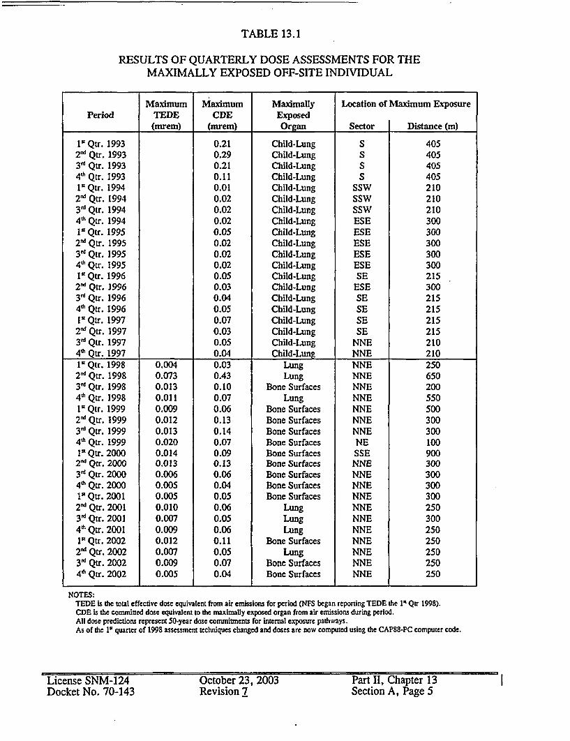
TABLE 13.1
RESULTS OF QUARTERLY DOSE ASSESSMENTS FOR THEMAXIMALLY EXPOSED OFF-SITE INDIVIDUAL
Maximum Maximum Maximally Location of Maximum ExposurePeriod TEDE CDE Exposed
(mrem) (mrem) Organ Sector Distance (m)
I" Qtr. 1993 0.21 Child-Lung S 4052n' Qtr. 1993 0.29 Child-Lung S 405311 Qtr. 1993 0.21 Child-Lung S 40546 Qtr. 1993 0.11 Child-Lung S 405I" Qtr. 1994 0.01 Child-Lung SSW 2102n' Qtr. 1994 0.02 Child-Lung SSW 2103 d Qtr. 1994 0.02 Child-Lung SSW 2104' Qtr. 1994 0.02 Child-Lung ESE 300Is Qtr. 1995 0.05 Child-Lung ESE 3002"' Qtr. 1995 0.02 Child-Lung ESE 3003rd Qtr. 1995 0.02 Child-Lung ESE 3004' Qtr. 1995 0.02 Child-Lung ESE 3001I Qtr. 1996 0.05 Child-Lung SE 2152"' Qtr. 1996 0.03 Child-Lung ESE 3003rd Qtr. 1996 0.04 Child-Lung SE 2154"' Qtr. 1996 0.05 Child-Lung SE 215I" Qtr. 1997 0.07 Child-Lung SE 215
2'V Qtr. 1997 0.03 Child-Lung SE 2153' Qtr. 1997 0.05 Child-Lung NNE 2104" Qtr. 1997 0.04 Child-Lung NNE 2101K Qtr. 1998 0.004 0.03 Lung NNE 250
2nd Qtr. 1998 0.073 0.43 Lung NNE 6503d Qtr. 1998 0.013 0.10 Bone Surfaces NNE 2004"'Qtr. 1998 0.011 0.07 Lung NNE 5501V Qtr. 1999 0.009 0.06 Bone Surfaces NNE 500
2 i Qtr. 1999 0.012 0.13 Bone Surfaces NNE 3003"d Qtr. 1999 0.013 0.14 Bone Surfaces NNE 3004"' Qtr. 1999 0.020 0.07 Bone Surfaces NE 100I" Qtr. 2000 0.014 0.09 Bone Surfaces SSE 900
2nd Qtr. 2000 0.013 0.13 Bone Surfaces NNE 3003"' Qtr. 2000 0.006 0.06 Bone Surfaces NNE 3004d' Qtr. 2000 0.005 0.04 Bone Surfaces NNE 3001" Qtr. 2001 0.005 0.05 Bone Surfaces NNE 300
2nd Qtr. 2001 0.010 0.06 Lung NNE 2503r' Qtr. 2001 0.007 0.05 Lung NNE 3004"h Qtr. 2001 0.009 0.06 Lung NNE 2501' Qtr. 2002 0.012 0.11 Bone Surfaces NNE 250
2"" Qtr. 2002 0.007 0.05 Lung NNE 2503' Qtr. 2002 0.009 0.07 Bone Surfaces NNE 2504d' Qtr. 2002 0.005 0.04 Bone Surfaces NNE 250
NOTES:TEDE Is the total effective dose equivalent from air emissions for period (NFS began reporting TEDE the 1I Qtr 1998).CDE is the committed dose equivalent to the maximally exposed organ from air emissions during period.All dose predictions represent 50-year dose commitments for internal exposure pathways,As of the 1' quarter of 1998 assessment techniques changed and doses are now computed using the CAP88-PC computer code.
License SNM-124Docket No. 70-143
October 23, 2003Revision 7
Part II, Chapter 13Section A, Page 5
I

Table 13.2ROUIMNE ENVIRONMENTAL MONITORING
SAMPLING LOCATIONSND WATER AMBIENT AIR VE(SURFACE WATER GROUM 3ETATION SOILUSEDIMENT
Asheville HighwaySampling Point (soil)
Martin CreekUpstream Sampling Point
NW Perimeter AirSampling Sta #170
Asheville HighwaySampling Point
Martin Creek DownstreamSampling Point
Well LD-IA0l West of twounderground 6,000-gallontanks
W Perimeter Air SamplingSta #171
Banner Hill RdSampling Point
Banner Hill RdSampling Point (soil)
Banner Spring BranchDownstream") SamplingPoint
S Perimeter Air SamplingSta #172
Little Mountain SamplingPoint
Little MountainSampling Point (soil)
Banner Spring Branch,Upstream Sampling Point
Well LD)-2A2) North oftwo underground 6,000-gallon tanks
NE Perimeter Air #1Sampling Sta #173
Burial Ground Samplingpoint
Highland Ave/First StSampling Point (soil)
Well 52Background Well
Highland Ave/First StSampling Point
Burial Ground atSampling Point (soil)
Nolichucky River UpstreamSampling Point
Nolichucky RiverDownstream Sampling Point
Wells 98A,99A, 100A100B, 101A102A, 103A104A, 105A,106A, QuarterlyDowngradient Wells
E Perimeter Air #1Sampling Sta #174
Nolichucky River UpstreamSampling Point (sediment)
E Perimeter Air #2Sampling Sta #218
Nolichucky RiverDownstream SamplingPoint (sediment)
NE Perimeter Air #2Sampling Sta #217
Martin Creek at UpstreamSampling Point (sediment)
Other"' Near Ponds 1 & 2 AirSampling Sta #555
Martin Creek atDownstream SamplingPoint #1 (sediment)
Martin Creek atDownstream SamplingPoint #2 (sediment)
W Perimeter Air SamplingSta #668
Banner Hill Rd AirSampling Sta #323
Banner Spring at UpstreamSampling Point (sediment)
Banner Spring atDownstream SamplingPoint (sediment)
Prk. LotfEnt Air SamplingSta #372
B. Hill/Stalling AirSampling Sta #381
License SNM-124Docket No. 70-143
October 23, 2003Revision 7
Part II, Chapter 13Section A, Page 6
I

Table 13.2 (Cont.)ENVIRONMENTAL MONITORING
SAMPLING LOCATIONSSURFACE WATER GROUND WATER AMBIENT AIR VEGETATION SOTUSEDIMENT
Stalling Ln SE AirSampling Sta #382
Highland/l 3 St AirSampling Sta #383
Spar Mill Rd Air SamplingSta #384
Security Fence SE AirSampling Sta #385
Asheville Hwy AirSampling Sta #324
North NFS Mound AirSampling Sta #553
Images West Sampling Sta#581
NFS Training CenterSampling Sta #582
Little Mountain AirSampling Sta #322
E of North NFS BurialGround Sampling Station#677
NE of North NFS BurialGround Sampling Station#678
N of North NFS BurialGround Sampling Station#679
SW Burial Trench AreaSampling Station #685
NOTES:(1) Samples are collected using a continuous, proportional sampler. In the event that this sampler becomes inoperable due to
power failure, mechanical breakage, etc., a daily grab sample will be collected.(2) Wells LDIA and LD2A are routinely collected when the underground storage tanks are in use.(3) In accordance with established procedures, a number of well samples are collected on a routine basis. At a minimum,
these are analyzed for gross alpha and beta radioactivity (see Figure 13.1).
License SNM-124 October 23, 2003 Part II, Chapter 13Docket No. 70-143 Revision 7 Section A, Page 7

Table 13.3EFFLUENT SAMPLING LOCATIONS'
Gaseous Effluents(Stacks/Vents)
Stack 416, Main StackStack 185, Building 131Stack 234, Building 234Stack 327, Building 330Stack 332, Building 120Stack 376, Building 301Stack 421, Building 100Stack 503, Building 530Stack 504, Building 520Stack 547, Building 100Stack 573, Building 306-WStack 600, Building 110Stack 615, Building 306-WStack 646, Building 110Stack 649, Building 330Stack 667, Building 410Stack 703, Building 307Stack 704, Building 307Stack 510, Building 510
Liquid Effluents(Streams)
Wastewater Treatment Facility (WWTF)
NFS Sanitary Sewer. BLEU Complex Sanitary Sewer
EPOTW Sludge
I
I
I
Note:I - Normally, samples are only collected from these locations when discharges occur (i.e., stack/vent
operates or facility discharges liquid effluents).
License SNM-124Docket No. 70-143
October 23, 2003Revision 7
Part II, Chapter 13Section A, Page 8
'I

FIGURE 13.1SITE GROUNDWATER MONITORING WELL LOCATIONS
RADAD
0 a__,0_
0 wwma MuL mLx I MJICIAR FUEL SERVICES, INC.,z L I _ . ._
t _in. _ O WELL _,,LOCATIONS! E 1 asM WM
W-100 Afl.# ~005-C0132-81D. . k e t N o .. 7 4 3 a! i-o_ n 1 -----. a eLicense SNM-124Docket No. 70-143
October I i, 2003Revision 7
rant II. tnapier lSetalion A, Page 9

15.14 OXIDE CONVERSION BUILDING - BUILDINA_
Inside the Oxide Conversion Building (OCB) low enriched uranyl nitrate (LE UN)solutions, up to 5 weight %235U, from the Uranyl Nitrate Building (UNB) and LE UNrecycle streams, up to 5 weight 235U, from within the OCB are mixed together and thencombined with ammonium hydroxide solution in a precipitator system. The precipitate,ammonium diuranate (ADU), is separated by a centrifuge and then processed in a dryerand calciner to uranium dioxide, U02 . A portion of the U0 2 is diverted to an oxidizer tobe processed to triuranium octaoxide, U308 . Batches of U0 2 and U308 are collected andmixed in a blender to make a homogenous mix of U02 and U3 08 before the uraniumoxide powder is loaded into shipping pails. The pails are placed in Type B shippingpackages and transported by truck to another licensed plant.
The processes inside the OCB include: LEU Feed Batch Make UP LEU Precipitation,LEU Oxide Production, and LEU Recovery. The location of s shown inChapter 10, FigurelO.l.
15.14.1 Safety Considerations
The document, Integrated Safety Analysis Summary Blended Low EnrichedUranium Project Oxide Conversion and Effluent Processing Buildings, containsdiscussions of the criticality safety, radiological safety, chemical safety, firesafety and environmental safety bases for the processes in the OCB. Therefore,the information provided in the section (Section 15.14) is limited to briefdescriptions of each of the OCB processes.
15.14.2 LEU Feed Batch Make Up
LE UN solution is pumped from the UNB storage tanks to a blend tank inside theOCB. If there is any LE UN recycle solution from LEU Recovery available, it isalso added to the blend tank. After the LE UN solution is mixed it is fed to aprecipitator system.
15.14.3 LEU Precipitation
The LE UN solution in the feed tank is heated by recirculating the solutionthrough a heater back into the feed tank. The LE UN solution in the feed tank isheated, which improves uranium precipitate separation later in a centrifuge.
License SNM-124 October 23, 2003 Part II, Chapter 15Docket No. 70-143 Revision 0 Section 14, Page 1

The LE UN solution is pumped to a precipitation tank. The LE UN solutionenters the precipitation tank through a spray nozzle. Ammonium hydroxidesolution, heated by an in-line heater, enters the precipitation tank. The twosolutions mix in this tank and a uranium precipitate, ammonium diuranate (ADU),is formed. The ADU slurry is continuously recirculated by a pump through aspray nozzle at the top of the tank. Monitoring the pH of the ADU slurry in theslurry recirculation loop controls the ammonium hydroxide solution flow into theprecipitation tank. Periodically dilute nitric acid solution is introduced to theprecipitation tank to flush out accumulated ADU solids.
The ADU slurry is pumped to a centrifuge feed tank. The centrifuge feed tankalso receives concentrate from the cross-flow filter in the LEU Recovery systemand recycle centrate solution from centrate receiver tanks. Ammonium hydroxidesolution is added to the centrifuge feed tank to raise the ADU slurry pH toincrease separation of the uranium precipitate in the centrifuge.
The ADU slurry is introduced into the center of a rotating centrifuge that forcesthe ADU solids to the inside wall of the vessel. An internal screw moves theADU solids to one end of the vessel concentrating and dewatering the solids. Aweir inside the centrifuge allows the liquid (centrate) to decant essentially free ofADU solids. The centrate is routed to a set of centrate receiver tanks. The ADUsolids fall by gravity into an auger that moves them to a dryer. Periodically thecentrifuge can be flushed with either dilute nitric acid or deionized water forcleanout.
15.14.4 LEU Oxide Production
The ADU solids fall by gravity from the end of the auger from the centrifuge intoa dryer. The dryer contains paddles that move the ADU solids from the inlet tothe outlet while contacting heated surfaces. The dryer reduces the moisturecontent of the ADU solids. Nitrogen flowing into the dryer sweeps the moistureevolving from the ADU solids out of the dryer. The temperature of the driedADU solids is monitored to control the heater for the dryer. The ADU solidsleave the dryer, pass into a chute and through a rotary valve. The rotary valveisolates the atmosphere in the dryer from the next piece of process equipment.
License SNM-124 October 23, 2003 Part II, Chapter 15Docket No. 70-143 Revision 0 Section 14, Page 2

A calciner, a rotary kiln, operates with a reducing, negative atmosphere at atemperature sufficient to convert the ADU to U0 2. The calciner has three heatingzones. Thermocouples measure the temperature at the surface of the calciner tubeand control the heating elements for each zone. The dried ADU solids exit thechute from the dryer to a feeder screw that moves the ADU solids into thecalciner. Hydrogen (a reducing agent) flows over the LE uranium solids in thecalciner. Nitrogen acts as a diluent gas. In the first zone of the calciner theremainder of the moisture in the ADU solids is removed. In the next zones anreaction takes place and the ADU is converted to U0 2.
The U0 2 from the calciner is routed to a solids blender feed hopper. Batches ofpowder are collected in the hopper and then added to the solids blender wherethey are mixed together to make a homogenous uranium oxide powder. Theuranium oxide powder is loaded into shipping pails at a station below the blender.
15.14.5 LEU Recovery
The centrate is pumped from the centrate receiver tanks to a uranium recoverysystem. The uranium recovery system in the OCB consists of a filter and an ionexchange resin column to remove uranium from the centrate solution from thecentrifuge. The filter removes the insoluble uranium. The ion exchange resinremoves soluble uranium. Both are used to return uranium to the process. Fromthe bottom of the ion exchange column the solution is then pumped to theadjacent Effluent Processing Building (EPB).
Miscellaneous tanks in this process area are used to store acid wash solutions,cleaned up uranium solution spills, and other uranium-bearing solutions to returnthe LEU to the process.
Off-specification LE uranium oxide powder is recycled to the process by threedifferent methods. (1) Add the off-specification LE uranium oxide powder to atwo-stage dissolution system. Nitric acid is combined with the LE uranium oxideto make LE UN solution. This LE UN solution is added to a receiver tank andthen pumped as needed to the blend tank to be combined with LE UN solutionfrom the UNB. (2) Add the off-specification LE uranium oxide powder back tothe solids blender. (3) Add the off-specification LE uranium oxide powder to thecalciner.
License SNM-124 October 23, 2003 Part II, Chapter 15Docket No. 70-143 Revision 0 Section 14, Page 3

15.15 EFFLUENT PROCESSING BUILDING - BUILDING 530
The liquid stream exiting the LEU Recovery System in the Oxide Conversion Building(OCB) enters the Effluent Processing Building (EPB) where ammonia is recovered forreuse in the OCB using an ammonia stripping column. The liquid waste from this systemis pumped to an evaporator to boil off water. The concentrated liquid waste is thensolidified using clay and cement in bulk bags. The bulk bags are then shipped to alicensed low-level radioactive waste disposal facility in accordance with applicableregulatory requirements.
The processes inside the EPB include: Amm2nia Recovery, Liquid Waste Treatment, andWaste Solidification. The location of Bldg. shown in Chapter 10, Figurel O. 1.
15.15.1 Safety Considerations
The document, Integrated Safety Analysis Summary Blended Low EnrichedUranium Project Oxide Conversion and Effluent Processing Buildings, containsdiscussions of the criticality safety, radiological safety, chemical safety, firesafety and environmental safety bases for the processes in the EPB. Therefore,the information provided in the section (Section 15.15) is limited to briefdescriptions of each of the EPB processes.
15.15.2 Ammonia Recovery
Liquid waste from the LE uranyl nitrate conversion process is primarily a 10%ammonium nitrate solution. This liquid waste is pumped from the OCB into areceipt tank inside the EPB. This receipt tank also receives liquid discharges fromthe ammonia recovery fume scrubber and an in-line sodium analyzer. Theammonia stripping column bottoms stream and the stripping column distillatestream can also be sent to the receipt tank.
Liquid waste in the receipt tank is periodically pumped to a feed tank for thestripping column. A sodium hydroxide solution is added to the liquid waste whileit is in the feed tank. The sodium hydroxide reacts with the ammonium nitrate toform ammonium hydroxide and sodium nitrate, which will allow the ammonia toreadily separate from the liquid waste stream while in the stripping column. Thesodium hydroxide feed rate is controlled by monitoring the pH of the liquid waste.The solution is then pumped to the stripping column through a heat exchangerthat is heated using the stripping column bottoms solution.
License SNM-124 October 23, 2003 Part II, Chapter 15Docket No. 70-143 Revision 0 Section 15, Page 1

The ammonia stripping column uses steam to separate out reusable ammonia.The ammonia vapor distillate leaving the column is routed through a water-cooledcondenser. The resulting liquid stream (ammonium hydroxide solution) iscollected in a distillate tank. Deionized water can be added to the vapor streamin the distillate tank to obtain the desired ammonia concentration in theammonium hydroxide solution. The solution is then pumped to the OCB'sammonium hydroxide tank for reuse. A sodium analyzer checks the distillate todetect any carryover of sodium from the stripping column. The bottoms streamfrom the stripping column is recycled back to the receipt tank or sent to the feedtank for Liquid Waste Treatment.
15.15.3 Liquid Waste Treatment
The stripping column bottoms stream, primarily a sodium nitrate solution, iscollected in a feed tank. This stream contains the radionuclides that did notprecipitate out with the ADU plus uranium at about 1 ppm. This tank serves aslag storage between the ammonia stripping column and an evaporator.
The sodium nitrate solution is pumped to a steam-heated evaporator where wateris boiled off thereby concentrating the sodium nitrate solution. The evaporatoroverhead stream (water vapor) is routed through a condenser and then to one oftwo overheads tanks. The water in the overheads tanks is sampled, analyzed,verified to meet the limits in the sewer discharge permit, and then discharged tothe sanitary sewer. The evaporator bottoms are routed through a cooler to abottoms tank.
15.15.4 Waste Solidification
The pH of the evaporator bottoms is adjusted with nitric acid while the solution isin the bottoms tank. The evaporator bottoms are then pumped to a mixer andcombined with clay and cement. The mixture is discharged into bulk bags to cureand then be shipped to a licensed disposal facility.
License SNM-124 October 23, 2003 Part II, Chapter 15Docket No. 70-143 Revision 0 Section 15, Page 2