air tester mpd5185510-03 19-5- · pdf file•••• detector tubes co-hp for...
TRANSCRIPT
Manufactured by Uniphos Envirotronic Pvt. Ltd. Nahuli (PO), Valsad (Dist),Gujarat-396108, INDIA For Assistance, Call on +91 2261233500 E-mail: [email protected] www.uniphos-she.com
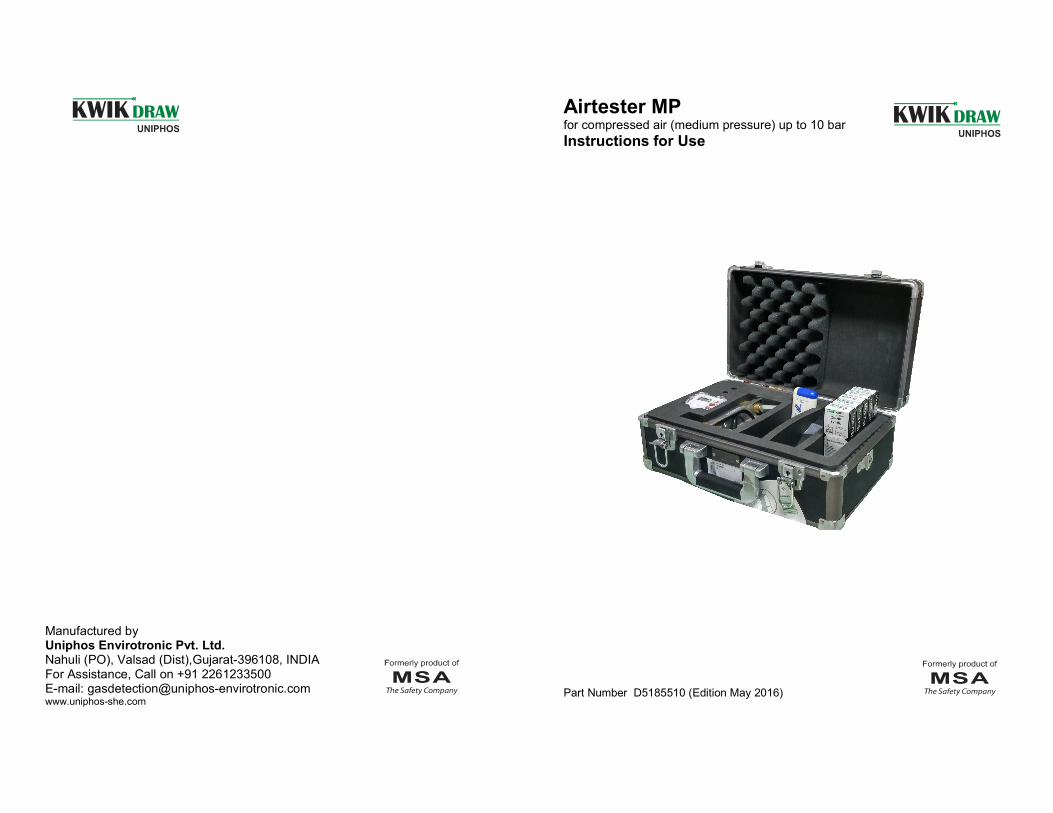
Airtester MP for compressed air (medium pressure) up to 10 bar
Instructions for Use
Part Number D5185510 (Edition May 2016)
Notice!
Like any piece of complex equipment, this product will do the job designed to do only if
it is used and serviced in accordance with the manufacturer`s instructions.
This manual must be carefully read by all individuals who have or will have the
responsibility for using or servicing the product. Before choosing and using this product,
it is required to assess whether this product is suitable for the application intended.
Choice and use are beyond the control of UNIPHOS. Therefore, the liability of
UNIPHOS covers only the consistent quality of this product. The above does not alter
statements regarding the warranties and conditions of sale and deliveries of UNIPHOS.
This symbol is used in these Instructions for use as a reference for warnings to avoid damage. These warnings are particularly important to prevent damage to the sampling-system-device and/or materials and persons.
- 2 -
Function checks should be made in regular intervals and if erroneous measurements are suspected.
6.2 Faults
If the detector tube holder is defective it must be replaced. In case of other faults (e.g., leaks), the device should be returned for repair to UNIPHOS.
7. Ordering information for spare parts and accessories Compressed air monitoring set “KWIKDRAW Airtester MP”
• complete with case containing: Sampling device (consisting of flow meter with needle valve, water level gauge, detector tube holder and connector), timer, device for breaking off detector tube tips, 10 detector tubes for measuring carbon monoxide, carbon dioxide, nitrous fumes, oil, water vapor (measuring range 100 ... 1000 mg/m3) one package each.
D5185710
Accessories and Spare Parts
•••• Sampling device Airtester MP D5185910
•••• Detector tubes CO-HP for measuring carbon monoxide, package of 10
D5085847
• Detector tubes CO2-HP for measuring carbon dioxide, package of 10
D5085848
• Detector tubes Nitr.-HP for measuring nitric oxide and nitrogen dioxide, package of 10
D5086850
• Detector tubes H2O-HP(mg/m3) for measuring water vapor (measuring range 5 ... 160 mg/m3), package of 10
D5085849
• Detector tubes H2O-MP(mg/m3) for measuring water vapor (measuring range 100 ... 1000 mg/m3), package of 10
D5086851
• Detector tubes Oil-HP Synth. for measuring oil, package of 10 D5085850
• Detector tube holder D4074058
• Timer D5185020
• Tube tip breaking device D5085012
• Connection hose on request
- 11 -

Note: After inserting the detector tube the float in the flowmeter will give a lower reading.
Before insertion of the detector tube After insertion of the detector tube. Do not adjust!
fig. 5 Adjusting the float
• Leave the float at the lower setting during measurement.(see fig. 5)
• Wait for timer signal and then close needle valve of sampling device immediately.
• Remove detector tube from holder.
• Take reading from the printed scale of the tube.
6 Maintenance
6.1 General
In view of the significance of the accuracy of the measuring results, the sampling device must be treated with care. Dirt must be avoided at all times, especially at the connection. Flushing and cleanliness control of the sampling device must be made as described in para. 5.2. After measuring is completed, the sampling device shall be stored in the case. The needle valve must be closed and the connection should be sealed with the protective cap.
- 10 -
Contents 1 Application .............................................................................................................. 03
2 Measuring Principle ................................................................................................ 04
3 Design .................................................................................................................... 05
4 Technical Data ....................................................................................................... 06
4.1 Sampling Device ........................................................................................... 06
4.2 Detector Tubes .............................................................................................. 06
5 Operating Instructions ............................................................................................ 07
5.1 Preparing for Measuring ................................................................................ 07
5.2 Measuring ..................................................................................................... 07
6 Maintenance ........................................................................................................... 10
6.1 General Remarks ........................................................................................... 10
6.2 Faults ............................................................................................................. 11
7 Ordering Information .............................................................................................. 11
1 Application
The compressed air monitoring set “KWIKDRAW Airtester MP“ (MP= medium pressure) is used to determine the content of water vapor, oil, carbon dioxide, carbon monoxide, nitrous fumes as well as other contaminations in respirable air from medium pressure compressors or medium pressure air lines (supplied air) up to 10 bar (145 psi). According to European Standard EN 12021 “Respiratory protective devices-Compressed air for breathing apparatus“, air for respiratory equipment in the range of medium pressure must meet the following quality requirements:
• Oil, especially compressor oil (vapor and mist) content max. 0.5 mg/m3
• CO2 content max. 500 ppm
• CO content max. 15 ppm Water content: “Air for compressed air line breathing apparatus shall have a dew point sufficiently low to prevent condensation and freezing. Where the apparatus is used and stored
-3-
at a known temperature the pressure dew point shall be at least 5°C below the likely lowest temperature. Where the conditions of usage and storage of the compressed air supply is not known the pressure dew point shall not exceed -11°C.“
The following table shows the maximum permissible water vapor content (mg/m3) for a dew point of -11°C, i.e. for unknown conditions of storage and usage.
Nominal pressure (bar)
Max. water content of air at atmospheric pressure
(mg/m3)
1 2190
2 1070
3 770
4 590
5 470
6 400
7 340
8 300
• Content of nitrous fumes (nitric oxide + nitrogen dioxide) is based on demand: “Compressed air for breathing apparatus shall not contain any contaminants at a concentration which may cause toxic and harmful effects and shall be far below the national exposure limit.“ The limit of concentration for nitrous fumes (NO + NO2) therefore usually is 0.5 ppm.
All maximum values are based on air at atmospheric pressure.
2 Measuring Principle
The air from the medium pressure compressor or air- line is reduced to atmospheric pressure and the required flow volume is set by the needle valve (flow meter) of the sampling device. The air flows through a specially calibrated detector tube for a specified time. The length of stain in the detector tube is an indication of the concentration of measured substance: this can be read directly on the detector tube scale.
- 4 –
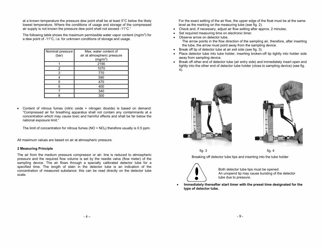
For the exact setting of the air flow, the upper edge of the float must be at the same level as the marking on the measuring tube (see fig. 2).
• Check and, if necessary, adjust air flow setting after approx. 2 minutes.
• Set required measuring time on electronic timer.
• Observe arrow on detector tube. The arrow points in the flow direction of the sampling air, therefore, after inserting the tube, the arrow must point away from the sampling device.
• Break off tip of detector tube at air exit side (see fig. 3).
• Place detector tube into tube holder, inserting broken-off tip tightly into holder side away from sampling device.
• Break off other end of detector tube (air entry side) and immediately insert open end tightly into the other end of detector tube holder (close to sampling device) (see fig. 4).
fig. 3 fig. 4
Breaking off detector tube tips and inserting into the tube holder
Both detector tube tips must be opened. An unopend tip may cause bursting of the detector tube due to pressure.
• Immediately thereafter start timer with the preset time designated for the type of detector tube.
- 9 -
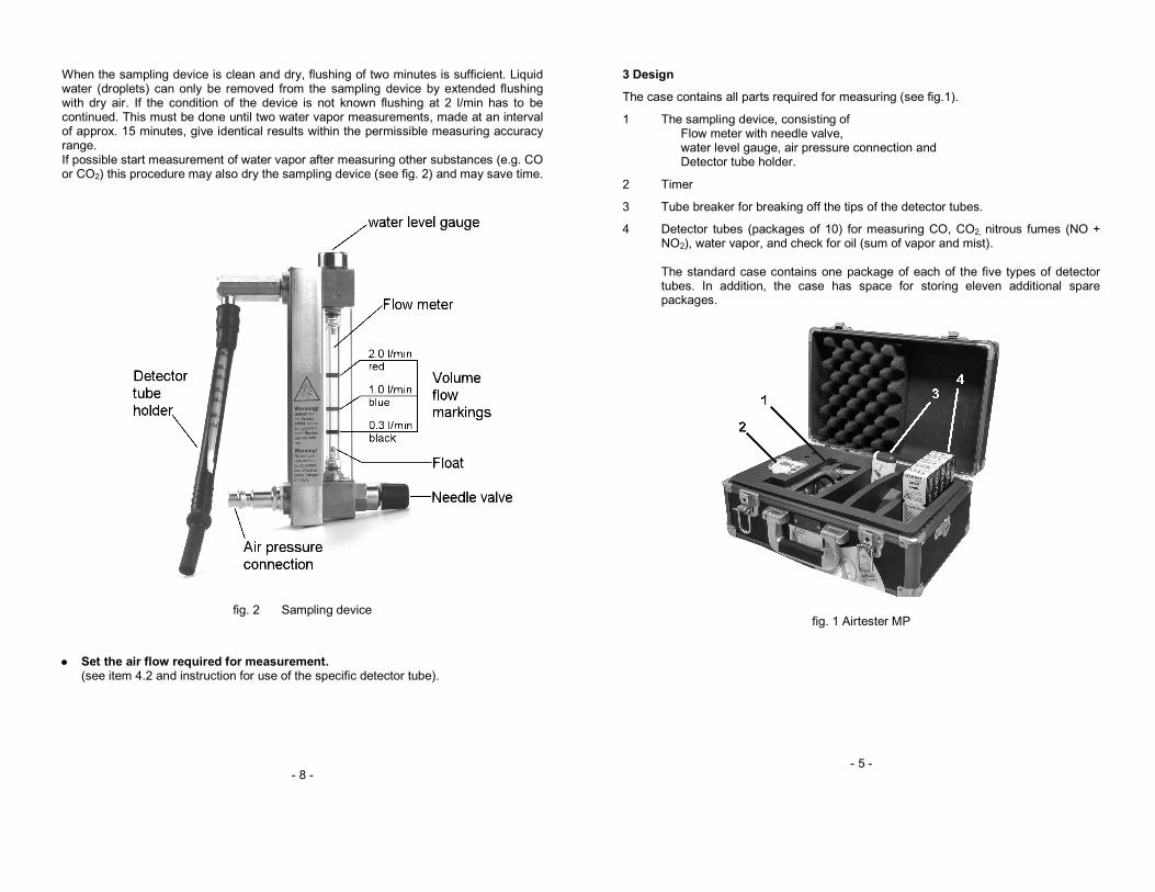
When the sampling device is clean and dry, flushing of two minutes is sufficient. Liquid water (droplets) can only be removed from the sampling device by extended flushing with dry air. If the condition of the device is not known flushing at 2 l/min has to be continued. This must be done until two water vapor measurements, made at an interval of approx. 15 minutes, give identical results within the permissible measuring accuracy range. If possible start measurement of water vapor after measuring other substances (e.g. CO or CO2) this procedure may also dry the sampling device (see fig. 2) and may save time.
fig. 2 Sampling device
•••• Set the air flow required for measurement. (see item 4.2 and instruction for use of the specific detector tube).
- 8 -
3 Design
The case contains all parts required for measuring (see fig.1).
1 The sampling device, consisting of Flow meter with needle valve, water level gauge, air pressure connection and Detector tube holder.
2 Timer
3 Tube breaker for breaking off the tips of the detector tubes.
4 Detector tubes (packages of 10) for measuring CO, CO2, nitrous fumes (NO + NO2), water vapor, and check for oil (sum of vapor and mist).
The standard case contains one package of each of the five types of detector tubes. In addition, the case has space for storing eleven additional spare packages.
fig. 1 Airtester MP
- 5 -

4 Technical Data
4.1 Sampling Device
Operating medium: air
Range of pressure: 29 psi up to 145 psi (2 bar up to 10 bar)
Flow: freely adjustable from 0.2 l/min to 3.0 l/min.
The measuring tube of the flow meter is marked ring-shaped for setting of the
required flow rate:
0.3 l/min - black 1.0 l/min - blue 2.0 l/min - red
Weight (with case): 3.1 kg
Dimensions (case):
Height 170 mm Width 250 mm Length 330 mm
4.2 Detector Tubes
Detector Tube Measuring Range Flow Rate (l/min)
Measuring Time (min)
Carbon monoxide CO-HP
5 ... 70 ppm 0.3 black marking
5
Carbon dioxide CO2-HP
100 ... 2000 ppm 0.3 black marking
5
Nitrous fumes (NO +NO2) Nitr.-HP
0.2 ... 2.5 ppm 0.5 ... 6.0 ppm
0.3 0.3
black marking
5 10
Oil Oil-HP synth.
e.g. 0.5 mg/m3 2.0 red marking
e.g. 30
Water vapor H2O-MP
100 ... 1000 mg/m3 1.0 blue marking
3
- 6 -
Note: All detector tubes described above are designed also for use with KWIKDRAW Air tester-HP (P/N 3188-701). This sampling device is for measuring compressed air in the high pressure (HP) range up to 300 bar e.g. compressed air cylinders and compressor charging panels. For measuring water vapor KWIKDRAW Detector Tube H2O-HP (P/N5085-849) measuring range 5 ... 160 mg/m3 is available. Detector tubes for other hazardous substances in compressed air for breathing apparatus can be supplied on request.
For all measurements note instructions for use that are included in the packages of the specific KWIKDRAW Detector Tubes.
5 Operating Instructions
5.1 Preparing for Measuring
• Clean connector of compressor, supplied air line or other source with a brief burst of air
•••• Connect sampling device to compressor or air line.
Never use sampling device with pressure higher than 10 bar. Glass tube of the flow meter may burst.. Before each use visually inspect the sampling device, particularly the glass tube of the flow meter, for damage.
• Adjust sampling device so that flow meter is vertical (use water level gauge on flow meter).
• Have timer ready.
• Have detector tubes ready. 5.2 Measuring
• Slowly open needle valve of sampling device and adjust a volume flow of 2 l/min.
• Flush device.
- 7 -