air slide table new - · pdf filetransfer of two lines of small objects onto a pallet sorting...
TRANSCRIPT

Transfer of two lines of small objects onto a pallet
Sorting of work pieces of different shapes continuously supplied by a conveyer, etc.
Air Slide TableReversible Typeø6, ø8, ø12, ø16, ø20, ø25
NewNew
Piping and adjuster positions can be changedon site to suit the installation conditions.
Application Examples
Compliant to RoHS directive
Series MXQR
Reversible design
CAT.ES20-203A

Lateral mounting(Through hole)
Lateral mounting(Body tapped)
Vertical mounting(Body tapped)
Air Slide Table/Interchangeable with the air slide table MXQ series.
Three types of mounting.Wider choice of mounting variations facilitates installation.
The body and workpiece mounting dimensions are interchangeable with those of the MXQ series.
Workpiece mounting tap
Dual rodTwice the output of conventional cylinders
Improved strengthEnd plate uses extra super duralumin.
Positioning holeImproved workpiece mounting repeatability
Integration of table and guide railMade of martensitic stainless steel
Recirculating linear guideWide type linear guide block body made of martensitic stainless steel
Body mounting through-hole
Positioning holeImproved body mountingrepeatability
Model
MXQR12-30
Accuracy (mm)
Parallelism
0.035
Height tolerance
±0.08
High Precision
It is possible to mount two auto switches on the same plane.
The auto switch can be mounted into the groove made on the side of the body with no projection.
Wide variety of adjuster options
Integration of the guide rail and the tableUses a recirculating linear guide for high rigidity and high precision.
Adjuster and pipingplaced on the same plane
Located on the same plane to facilitate piping work.
Features 1

How to change the adjuster
Wide Variety of Adjuster (Option)
Adjuster
Guide block location peg
Reverse
Remove the adjuster. Reverse the body. Refit → Completed
Rubber stopper on both ends Extension stroke end shock absorber +Retraction stroke end rubber stopper
Shock absorber on both ends Extension stroke end metal stopper +Retraction stroke end shock absorber
Variations
MXQR 6MXQR 8MXQR12MXQR16MXQR20MXQR25
68
12162025
ModelBoresize
(mm)10 20 30 40 50 75 100 125 150
Standard stroke (mm) Adjuster (Option)
Rubber stopperExtensionstroke end
Retractionstroke end Both ends
Shock absorberExtensionstroke end
Retractionstroke end Both ends
Metal stopperExtensionstroke end
Retractionstroke end Both ends
Metal stopper on both ends Extension stroke end rubber stopper +Retraction stroke end metal stopper
( ) The MXQR6 series does not have a shock absorber type (J, JS, JT).
Shock absorber(soft type/short stroke RJ) can be mounted. (ø8 to ø25)
Shock absorber (RB) can be mounted on ø6.
Improved cycle time, suitable for short strokes.
Features 2

3-1
3-2
3-3
3-4
1
2
3
L2+A
5
L3
L1
Series MXQRModel Selection
Model Selection Step Formula/Data Selection Example
Operating Conditions
Enumerate the operating conditions considering the mounting position and workpiece configuration.
• Model to be used• Type of cushion• Workpiece mounting position• Mounting orientation • Average speed Va (mm/s)• Load weight W (kg): Fig. (1)• Overhang Ln (mm): Fig. (2)
Cylinder: MXQR16-50Cushion: Rubber stopperWorkpiece table mountingMounting: Horizontal wall mountingAverage speed: Va = 300 [mm/s]Load weight: W = 1 [kg]L1 = 10 mm L2 = 30 mm L3 = 30 mm
Kinetic Energy
Find the kinetic energy E (J) of the load.
Find the allowable kinetic energy Ea (J).Confirm that the kinetic energy of the load does not exceed the allowable kinetic energy.
Ea = K • E max
1 V 2E = —— • W (————) 2 1000 Collision speed V = 1.4 • Va —— ∗
Workpiece mounting coefficient K: Fig. (3)
Max. allowable kinetic energy Emax: Table (1)
Kinetic energy (E) ≤ Allowable kinetic energy (Ea)
∗) Correction factor (Reference values)
1 420 2E = —— • 1 (————) = 0.088 2 1000
V = 1.4 x 300 = 420
Ea = 1 x 0.11 = 0.11
Can be used based on E = 0.088 ≤ Ea = 0.11
Load Factor
Load Factor of Load WeightFind the allowable load weight Wa (kg).Note) No need to consider this load
factor in the case of using perpendicularly in a vertical position. (Define α1 = 0.)
Find the load factor of the load weight α1.
Wa = K • β • Wmax Workpiece mounting coefficient K: Fig. (3) Allowable load weight coefficient β: Graph (1) Max. allowable load weight Wmax: Table (2)α1 = W/Wa
Wa = 1 x 1 x 4 = 4 K = 1 β = 1 Wmax = 4α1 = 1/4 = 0.25
Load Factor of the Static Moment
Find the static moment M (N·m).
Find the allowable static moment Ma (N·m).
Find the load factor α2 of the static moment.
M = W x 9.8 (Ln + An)/1000 Correction value of moment center position distance An: Table (3)
Ma = K • γ • Mmax Workpiece mounting coefficient K: Fig. (3) Allowable moment coefficient γ: Graph (2) Maximum allowable moment Mmax: Table (4)
α2 = M/Ma
Examine My.My = 1 x 9.8 (10 + 30)/1000 = 0.39 A3 = 30May = 1 x 1 x 18 = 18 Mymax = 18 K = 1 γ = 1
α2 = 0.39/18 = 0.022
RollingYawing
Examine Mr.Mr = 1 x 9.8 (30 + 10.5)/1000 = 0.39 A6 = 10.5Mar = 36 Mrmax = 36 K = 1 γ = 1
α'2 = 0.39/36 = 0.011
Load Factor of Dynamic Moment
Sum of the Load Factors
Find the dynamic moment Me (N·m).
Find the allowable dynamic moment Mea (N·m).
Find the load factor α3 of the dynamic moment.
(Ln + An)Me = 1/3 • We x 9.8 ————— 1000 Collision equivalent to impact We = δ • W • V
δ: Bumper coefficient Rubber stopper without adjuster = 4/100 Shock absorber = 1/100 Metal stopper= 16/100
Correction value of moment center position distance An: Table (3)
Mea = K • γ • Mmax Workpiece mounting coefficient K: Fig. (3) Allowable moment coefficient γ: Graph (2) Max. allowable moment Mmax: Table (4)
α3 = Me/Mea
Examine Mep. (30 + 10.5)Mep = 1/3 x 16.8 x 9.8 x ——————— = 2.2 1000 We = 4/100 x 1 x 420 = 16.8 A2 = 10.5Meap = 1 x 0.7 x 18 = 12.6 K = 1 γ = 0.7Mpmax = 18α3 = 2.2/12.6 = 0.17
Examine Mey. (30 + 24.5)Mey = 1/3 x 16.8 x 9.8 x ——————— = 3.0 1000 We =168 A4 = 24.5Meay = 12.6 (Same value as Meap)α'3 = 3.0/12.6 = 0.24
Pitching
Yawing
Use is possible if the sum of the load factors does not exceed 1. Σαn = α1 + α2 + ·········· + αn ≤ 1
Σαn = α1 + α2 + α'2 + α3 + α'3= 0.25 + 0.022 + 0.011 + 0.17 + 0.24 = 0.693 ≤ 1
And it is possible to use.
Front matter 1

An (n = 1 to 6)EEmaxLn (n = 1 to 3)M (Mp, My, Mr)Ma (Map, May, Mar)Me (Mep, Mey)Mea (Meap, Meay)Mmax (Mpmax, Mymax, Mrmax)V
Correction value of moment center position distanceKinetic energyAllowable kinetic energyOverhangStatic moment (Pitch, Yaw, Roll)Allowable static moment (Pitch, Yaw, Roll)Dynamic moment (Pitch, Yaw) Allowable dynamic moment (Pitch, Yaw) Maximum allowable moment (Pitch, Yaw, Roll)Collision speed
Unitmm
JJ
mmN·mN·mN·mN·mN·m
mm/s
SymbolVaWWaWeWmaxαβγK
DefinitionAverage speedLoad weightAllowable load weightWeight equivalent to impactMax. allowable load weightLoad factorAllowable load weight coefficientAllowable moment coefficientWorkpiece mounting coefficient
Unitmm/s
kgkgkgkg————
Symbol
MXQR 6MXQR 8MXQR12MXQR16MXQR20MXQR25
Model10 1.42.04.7
13 19 32
1.0
0.7
0.5
0.4
0.3
0.2
50 100 200 300 500 700
1.0
0.7
0.5
0.4
0.3
0.2
50 100 200 300 500 700
MXQR 6MXQR 8MXQR12MXQR16MXQR20MXQR25
Model
1014.516.521 27 29.535.5
Correction value of moment center position distance (Refer to Figure (2).)
MXQR 6MXQR 8MXQR12MXQR16MXQR20MXQR25
Model
0.612469
MXQR 6MXQR 8MXQR12MXQR16MXQR20MXQR25
Model
Allowable kinetic energy
Withoutadjuster
0.0180.0270.0550.11 0.16 0.24
Rubberstopper
Shockabsorber
Metalstopper
Maximumallowable
load weight
W
W
K = 1
K = 0.6
W
Mp
L1 A1
W
Mp
L1 A2
Mep
A2
L3
Mey
L2A
4
W
My
L2 A3
W
My
L2 A4
W
Mr
L3 A5
W
Mr
L3 A6
0.0180.0270.0550.11 0.16 0.24
0.0360.0540.11 0.22 0.32 0.48
0.0090.0130.0270.0550.0800.12
Adjuster option
A1, A3
Stroke (mm) A2 A4 A5 A6
2014.516.521 27 29.535.5
3014.518.521 27 29.535.5
4018.520.525 27 29.535.5
5018.528 25 30 33.543
75—
28.534 33 37.543
100——
34 42.553.550
125———
42.555 64
150————
56.564
6 7 9
10.514 16.5
13.516 19.524.530 37
13.516 19.524.530 37
6 7 9
10.514 16.5
Stroke (mm)20 1.42.04.7
13 19 32
30 1.42.84.7
13 19 32
40 2.83.77.2
13 19 32
50 2.87.97.2
18 27 52
75—
7.915 23 36 52
100——15428478
125——— 42 84140
150———— 84140
10 3.55.1
11 31 47 81
20 3.55.1
11 31 47 81
30 3.56.0
11 31 47 81
40 5.16.9
13 31 47 81
50 5.1 7.413 36 57
110
75—
7.4 14 41 66 110
100—— 14 41 75130
125——— 41 75130
150———— 75130
Pitch/Yaw moment: Mpmax/MymaxStroke (mm)
Roll moment: Mrmax
Note) For A2, A4, A5 and A6, there is no difference in the corrected values due to the stroke.
Caution
W
W
W
Definition
• The maximum operating speed for the metal stopper type is 200 mm/s.
• When the shock absorber type is mounted vertically, operate within the maximum allowable load weight range shown in Table (2).
• The operating pressure range of the MXQR6 with shock absorber is 0.3 to 0.7 MPa.
Symbol
Fig. (1) Load Weight: W (kg)
Fig. (2) Overhang: Ln (mm),Correction Value of Moment Center Position Distance: An (mm)
Fig. (3) Workpiece Mounting Coefficient: K
Note) No need to consider this load factor in the case of using perpen-dicularly in a vertical position.
Pitch moment Yaw moment Roll moment Table mounting
End plate mounting
Sta
tic m
omen
tD
ynam
ic m
omen
t
Note) Static moment: Moment generated by gravityDynamic moment: Moment generated by impact when colliding with stopper
Table (1) Allowable Kinetic Energy: Emax (J) Table (2) Maximum Allowable Load Weight: Wmax (kg)
Graph (1) Allowable Load Weight Coefficient: β
Allo
wab
le lo
ad w
eigh
t coe
ffici
ent:
β
Average speed Va (mm/s)
Graph (2) Allowable Moment Coefficient: γ
Allo
wab
le m
omen
t coe
ffici
ent:
γ
Average speed Va (mm/s) Collision speed V (mm/s)
Note) Use the average speed when calculating static moment.Use the collision speed when calculating dynamic moment.
Table (3) Correction Value of Moment Center Position Distance: An (mm)
Table (4) Maximum Allowable Moment: Mmax (N·m)
Front matter 2
Air Slide Table/Reversible Type Series MXQR
a

Buf
fer
time
(s)
Operating pressure (MPa)0.1 0.2 0.3 0.4 0.5 0.6
1.6
1.4
1.2
1.0
0.8
0.6
0.4
0.2
0.0
Buf
fer
time
(s)
Operating pressure (MPa)0.1 0.2 0.3 0.4 0.5 0.6
0.5
0.4
0.3
0.2
0.1
0.0
Buf
fer
time
(s)
Operating pressure (MPa)0.1 0.2 0.3 0.4 0.5 0.6
0.5
0.4
0.3
0.2
0.1
0.0
Buf
fer
time
(s)
Operating pressure (MPa)0.1 0.2 0.3 0.4 0.5 0.6
0.5
0.4
0.3
0.2
0.1
0.0
Buf
fer
time
(s)
Operating pressure (MPa)0.1 0.2 0.3 0.4 0.5 0.6
0.5
0.4
0.3
0.2
0.1
0.0
Buf
fer
time
(s)
Operating pressure (MPa)0.1 0.2 0.3 0.4 0.5 0.6
1.6
1.4
1.2
1.0
0.8
0.6
0.4
0.2
0.0B
uffe
r tim
e (s
)
Operating pressure (MPa)0.1 0.2 0.3 0.4 0.5 0.6
0.5
0.4
0.3
0.2
0.1
0.0
Buf
fer
time
(s)
Operating pressure (MPa)0.1 0.2 0.3 0.4 0.5 0.6
0.5
0.4
0.3
0.2
0.1
0.0
Buf
fer
time
(s)
Operating pressure (MPa)0.1 0.2 0.3 0.4 0.5 0.6
0.5
0.4
0.3
0.2
0.1
0.0
Buf
fer
time
(s)
Operating pressure (MPa)0.1 0.2 0.3 0.4 0.5 0.6
0.5
0.4
0.3
0.2
0.1
0.0
∗ Buffer time: The time from when the product hits the rod end of the shock absorber to when the shock absorber reaches its retracted position.
MXQR8 Extension Stroke End
MXQR12 Extension Stroke End
MXQR16 Extension Stroke End
MXQR20 Extension Stroke End
MXQR25 Extension Stroke End
MXQR8 Retraction Stroke End
MXQR12 Retraction Stroke End
MXQR16 Retraction Stroke End
MXQR20 Retraction Stroke End
MXQR25 Retraction Stroke End
Test conditionsWorkpiece weight : Approx. 70% of maximum load weightSpeed : Average speed with the fitting directly mounted (Approx. 300 to 500 mm/s
depending on the bore size and operating pressure)
Note) The buffer time depends on the operating conditions (maximum load weight, moment, piston speed and operating pressure and temperature).
RB
RB
RB
RB
RB
RB
RJ shortstroke typeRJ short
stroke type
RJ shortstroke type
RJ shortstroke type
RJ shortstroke type
RJ shortstroke type
RJ shortstroke type
RB
RJ shortstroke type
RB
RJ shortstroke type
RBRJ shortstroke type
RB
Adjuster Option: Shock Absorber Buffer Time (Reference Values) Selection
Caution1. Operate loads within the range of
the operating limits.Select the model considering maximum load weight and allowable moment. Refer to front matters 1 and 2 for the details. When actuator is used outside of operating limits, eccentric loads on guide will be in excess of this causing vibration on guide, inaccuracy, and shortened life.
2. If intermediate stops by external stopper is done, avoid ejection.If lurching occurs damage can result. When making a stop with an external stopper to be followed by continued forward movement, first supply pressure to momentarily reverse the table, then retract the intermediate stopper, and finally apply pressure to the opposite port to operate the table again.
Operating Environment
Caution1. Do not use in the environment,
where the product could be exposed to the liquid such as cutting oil, etc.Using in the environment where the product could be exposed to cutting oil, coolant or oil, etc. could result in looseness, increased operating resistance, or air leakage, etc.
2. Do not use in the environment, where the product could be exposed directly to the foreign matters such as powder dust, blown dust, cutting chip, spatter, etc.This could result in looseness and increased operating resistance, and air leakage, etc.Please consult with SMC regarding use in this kind of environment.
3. Use caution for the anti-corrosiveness of linear guide section.Martensitic stainless steel is used for the table and guide block. But, use caution that anti-corrosiveness is inferior to the austenitic stainless steel. Especially, rust may be generated in an environment where waterdrops are likely to adhere due to condensation, etc.
Front matter 3
Series MXQR
a

10, 20, 30, 40, 5010, 20, 30, 40, 50, 7510, 20, 30, 40, 50, 75, 10010, 20, 30, 40, 50, 75, 100, 12510, 20, 30, 40, 50, 75, 100, 125, 15010, 20, 30, 40, 50, 75, 100, 125, 150
ø6ø8
ø12ø16ø20ø25
Bore size (Stroke (mm))
MXQR 12 50 M9BWJL
Port thread type
Nil
TNTF
M threadRc
NPTG
ø6 to ø16
ø20, ø25
Adjuster options
NoneAdjuster(Rubberstopper)
Shockabsorber
(RB)
Adjuster(Metal
stopper)
Shock absorber
RJ Note 1, 2)
(Short stroke type)NoneAdjuster (Rubber stopper)Shock absorber (RB)Adjuster (Metal stopper)
Shock absorber RJ Note 1, 2)
(Short stroke type)
Retraction stroke end
NilASBSCS
JS
ATA
BSATCSAT
JSAT
BTASBT
BCSBT
JSBT
CTASCTBSCT
C
JSCT
JTASJTBSJTCSJT
J
Made to OrderRefer to page 2 for details.Air Slide Table/
Reversible Type
Applicable Auto Switches/Refer to Best Pneumatics No. 3 for further information on auto switches.
LLeft side Right side
Nil
Adjuster position setat the time of shipment
∗ The adjuster position can be selected from two choices, right side and left side. It can be changed on site to suit the installation conditions. For detailed dimensions, refer to the product drawing. For the procedure for changing the position, refer to the MXQR Operation Manual.
Adjuster
Table
Adjuster
Table
Note 1) The shock absorber RJ (short stroke type) is a soft and short stroke type shock absorber (RJ�). For the buffer time, refer to front matter 3. For details of the shock absorber (RJ), refer to its catalog.
Note 2) The shock absorber (short stroke type) is not available with the MXQR6.
How to Order
Auto switchNil Without auto switch (Built-in magnet)
∗ For applicable auto switch models, refer to the below table.
∗ Lead wire length symbols: 0.5 m ········· Nil (Example) M9NW1 m ·········· M (Example) M9NWM3 m ·········· L (Example) M9NWL5 m ·········· Z (Example) M9NWZ
∗ Solid state auto switches marked with “ ” are produced upon receipt of order.
∗ Since there are other applicable auto switches than listed, refer to page 26 for details.∗ For details about auto switches with pre-wired connector, refer to pages 1784 and 1785 of Best Pneumatics No. 3.∗ Auto switches are shipped together, (but not assembled).
Exte
nsio
n st
roke
end
∗
2 pcs.1 pc.
“n” pcs.
NilSn
Number of auto switches
∗1 Water resistant type auto switches can be mounted on the above models, but in such case SMC cannot guarantee water resistance. ∗2 1 m type lead wire is only applicable to D-A93.
IC circuit
—IC circuit
IC circuit
—
IC circuit
—
IC circuit
—
—
Relay, PLC
Relay, PLC
Applicableload
Pre-wiredconnector
Lead wire length (m)0.5(Nil)
5(Z)
1(M)
3(L)
A96V
A93V∗2
A90V
M9NVM9PVM9BV
M9NWVM9PWVM9BWVM9NAV∗1
M9PAV∗1
M9BAV∗1
Perpendicular
A96
A93A90
M9NM9PM9B
M9NWM9PWM9BWM9NA∗1
M9PA∗1
M9BA∗1
Auto switch model
In-line
—
24 V
24 V
—
100 V100 V or less
—
5 V
12 V
5 V,12 V
12 V
5 V,12 V
12 V
5 V,12 V
12 V
Load voltage
DC AC
3-wire(NPN equivalent)
2-wire
Yes
No
Yes
Grommet
Grommet
3-wire (NPN) 3-wire (PNP)
2-wire3-wire (NPN)3-wire (PNP)
2-wire3-wire (NPN)3-wire (PNP)
2-wire
Wiring (Output)
—
—
Indica
tor lig
ht
Type Special function Electricalentry
Ree
d au
tosw
itch
So
lid s
tate
auto
sw
itch
Diagnostic indication(2-color indication)
Water resistant(2-color indication)
1
ø6, ø8, ø12, ø16, ø20, ø25Series MXQRAir Slide Table/Reversible Type
A

When operating an actuator with a small diameter and a short stroke at a high frequency, the dew condensation (water droplet) may occur inside the piping depending on the conditions. Simply connecting the moisture control tube to the actuator will prevent dew condensation from occur-ring. For details, refer to Series IDK in the WEB catalog.
MoistureControl TubeSeries IDK
Piping port size
Fluid
Action
Operating pressure
Proof pressure
Ambient and fluid temperature
Bore size (mm)
Air
Double acting
0.15 to 0.7 MPa∗
1.05 MPa
–10 to 60°C
50 to 500 mm/s(Adjuster option/Metal stopper: 50 to 200 mm/s)
(Adjuster option/Shock absorber: 300 to 500 mm/s [ø6 only])
Rubber bumper (Standard, Adjuster option/Rubber stopper)Shock absorber (Adjuster option/Shock absorber)
None (Adjuster option/Metal stopper)
+1 0
Not required (Non-lube)
Reed auto switch (2-wire, 3-wire)Solid state auto switch (2-wire, 3-wire)
2-color indication solid state auto switch (2-wire, 3-wire)
mm
M5 x 0.8
Piston speed
Cushion
Lubrication
Auto switch
Stroke length tolerance
6 8 12 16 20 25Rc1/8, NPT1/8, G1/8
MXQR 6MXQR 8MXQR12MXQR16MXQR20MXQR25
Standard stroke (mm)
10, 20, 30, 40, 50
10, 20, 30, 40, 50, 75
10, 20, 30, 40, 50, 75, 100
10, 20, 30, 40, 50, 75, 100, 125
10, 20, 30, 40, 50, 75, 100, 125, 150
10, 20, 30, 40, 50, 75, 100, 125, 150
Model
0.2
11
8
20
15
45
34
80
60
126
94
196
151
Bore size (mm)
Rod size(mm)
Piston area(mm2)
Operatingdirection
Operating pressure (MPa)
6
8
12
16
3
4
6
8
OUT
IN
57
42
OUT
IN
101
75
OUT
IN
226
170
OUT
IN
402
302
0.3
17
13
30
23
68
51
121
91
188
141
295
227
0.4
23
17
40
30
90
68
161
121
251
188
393
302
0.5
29
21
51
38
113
85
201
151
314
236
491
378
0.6
34
25
61
45
136
102
241
181
377
283
589
454
0.7
40
29
71
53
158
119
281
211
440
330
687
529
The dual rod ensures an output twice that of existing cylinders. (N)
Note) Theoretical output (N) = Pressure (MPa) x Piston area (mm2)
∗ MXQR6 with shock absorber: Operating pressure 0.3 to 0.7 MPa
20 10
25 12
OUT
IN
628
471
OUT
IN
982
756
INOUT
MXQR 6MXQR 8MXQR12MXQR16MXQR20MXQR25
Model
Standard stroke (mm)
(g)
Additional weight of adjuster option
100
140
335
605
1100
1750
120
170
340
610
1100
1750
140
210
380
670
1100
1750
180
250
450
735
1200
1950
200
315
490
835
1400
2400
—
385
655
1000
1750
2750
—
—
745
1250
2350
3450
—
—
—
1400
2650
4300
—
—
—
—
2900
4700
6
10
25
45
80
130
5
10
23
40
65
110
Rubber stopper
14
30
47
75
170
220
10
23
30
53
120
140
Shock absorber
10
23
35
60
115
180
5
10
23
40
65
110
Metal stopper
Extensionstroke end
Retractionstroke end
Extensionstroke end
Retractionstroke end
Extensionstroke end
Retractionstroke end
Symbol Specifications
PTFE grease
Grease for food processing equipment
Long adjustment bolt (Adjustment range: 15 mm)
Long adjustment bolt (Adjustment range: 25 mm)
Heat treated metal stopper bolt (Adjustment range: 5 mm)
Heat treated metal stopper bolt (Adjustment range: 15 mm)
Heat treated metal stopper bolt (Adjustment range: 25 mm)
Without built-in auto switch magnet
Fluororubber seal
Anti-corrosive guide unit
EPDM seal
-X7-X9-X11-X12-X16-X17-X18-X33-X39-X42-X45
Made to Order(For details, refer to pages 28 to 29.)
Specifications
Standard Stroke
Theoretical Output
Weight
10 20 30 40 50 75 100 125 150
2
Series MXQR
B
Extension stroke end shock absorber
Retraction stroke end rubber stopper
Extension stroke end rubber stopper
Extension stroke end metal stopper
Retraction stroke end metal stopper
Retraction stroke end shock absorber
Applicable bore size
Adjustment rangeNil
-X11-X12
MXQR
5 mm15 mm25 mm
68
12162025
12 X11Adjuster options
AS
Standard
Option
ø6ø8
ø12ø16ø20ø25
Note 1) -X12 (adjustment range: 25 mm) is not available with the MXQR6 series.Note 2) -X11 and -X12 are not available with shock absorber.Note 3) Shock absorber (RJ) (JS, JT) is not available with the MXQR6 series.Note 4) MXQR6 with shock absorber (RB) – Operating pressure 0.3 to 0.7 MPa
Operating piston speed 300 to 500 mm/sNote 5) For dimensions, refer to pages 20 to 24.∗ At the time of shipment, the standard mounting is applied.
Extension stroke endRetraction stroke endExtension stroke endRetraction stroke endExtension stroke endRetraction stroke endExtension stroke endRetraction stroke end
ASATBSBTCSCTJSJT
Rubberstopper
Shock absorber (RB)
Shock absorber RJshort stroke type
Metalstopper
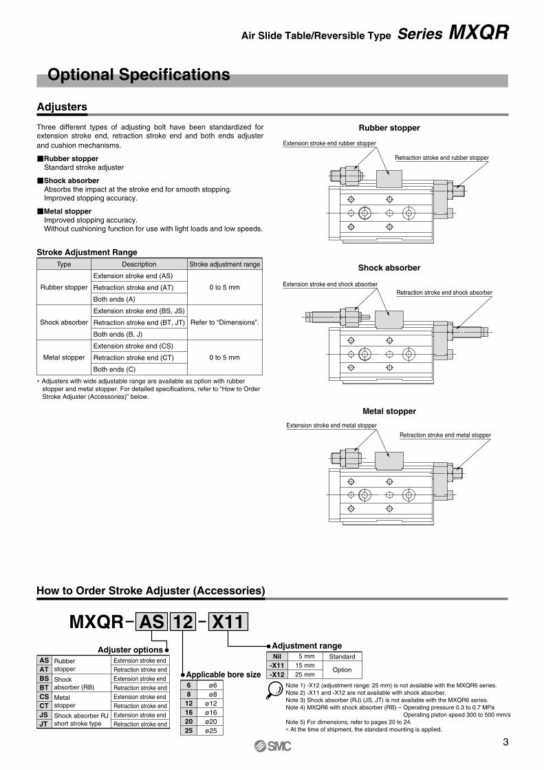
Adjusters
Rubber stopper
Shock absorber
Metal stopper
∗ Adjusters with wide adjustable range are available as option with rubber stopper and metal stopper. For detailed specifications, refer to “How to Order Stroke Adjuster (Accessories)” below.
Stroke Adjustment RangeType Description Stroke adjustment range
0 to 5 mm
Refer to “Dimensions”.
0 to 5 mm
Extension stroke end (AS)
Retraction stroke end (AT)
Both ends (A)
Extension stroke end (BS, JS)
Retraction stroke end (BT, JT)
Both ends (B, J)
Extension stroke end (CS)
Retraction stroke end (CT)
Both ends (C)
Rubber stopper
Shock absorber
Metal stopper
Three different types of adjusting bolt have been standardized for extension stroke end, retraction stroke end and both ends adjuster and cushion mechanisms.
�Rubber stopperStandard stroke adjuster
�Shock absorberAbsorbs the impact at the stroke end for smooth stopping. Improved stopping accuracy.
�Metal stopperImproved stopping accuracy.Without cushioning function for use with light loads and low speeds.
Optional Specifications
How to Order Stroke Adjuster (Accessories)
3
Air Slide Table/Reversible Type Series MXQR

M
W
C B
A
Radialclearance
(mm)
Model
B side parallelism to A side
B side traveling parallelism to A side
C side perpendicularity to A side
M dimension tolerance
W dimension tolerance
Radial clearance (μm)
MXQR6
Refer to Table (1).
Refer to Graph (1).
0.05 mm
±0.08 mm (±0.1 mm)∗
±0.1 mm
–4 to 0
MXQR8
–4 to 0
MXQR12
–6 to 0
MXQR16
–10 to 0
MXQR20
–12 to 0
MXQR25
–14 to 0
∗ ±0.1 mm for 75 mm or longer stroke
MXQR 6
MXQR 8
MXQR12
MXQR16
MXQR20
MXQR25
ModelStroke (mm)
10
0.025
0.025
0.03
0.035
0.04
0.045
20
0.03
0.03
0.03
0.035
0.04
0.045
30
0.035
0.035
0.035
0.04
0.04
0.045
40
0.04
0.04
0.04
0.045
0.045
0.05
50
0.045
0.055
0.045
0.05
0.055
0.06
75
—
0.065
0.065
0.065
0.07
0.07
100
—
—
0.075
0.08
0.095
0.09
125
—
—
—
0.095
0.105
0.115
150
—
—
—
—
0.125
0.125
0.06
0.04
0.02
0
Trav
elin
g pa
ralle
lism
(m
m)
50 100 150Stroke (mm)
(mm)
Shock absorber model
Applicable slide table
Max. absorbed energy (J)
Stroke absorption (mm)
Collision speed (mm/s)
Max. operating frequency (cycle/min)
Max. allowable thrust (N)
Ambient temperature range (°C)
RB0604-X2062
MXQR6 MXQR8 MXQR12 MXQR16 MXQR20 MXQR25
0.5
4
300 to 500
—
150
1.34
3.89
5.5
RB0805
0.98
5
80
245
1.96
3.83
15
RB0806 RB1007 RB1411 RB1412
2.94
6
80
245
1.96
4.22
15
5.88
7
70
422
4.22
6.86
25
14.7
11
45
814
6.86
15.3
65
19.6
12
45
814
6.86
15.98
65
50 to 500
–10 to 60
RJ Short Stroke Type Specifications
—
MXQR6
—
MXQR8 MXQR12 MXQR20 MXQR25
RJ0805
0.5
5
80
245
2.8
4.9
15
RJ1006
MXQR16
RJ1410
1.5
6
50 to 500
70
422
–10 to 60°C (No freezing)
5.4
8.0
23
3.7
10
45
814
6.4
14.6
65
Applicable sizeMXQR 6MXQR 8MXQR12MXQR16MXQR20MXQR25
Shock absorber modelRB0604-X2062
RB0805RB0806RB1007RB1411RB1412
—
RJ0805
RJ1006
RJ1410
Service Life and Replacement Period of Shock Absorber
Caution
Table Accuracy
Table (1) B Side Parallelism to A Side
Graph (1) B Side Traveling Parallelism to A Side
Traveling parallelism:The amount of deflection on a dial gauge when the table travels a full stroke with the body secured on a reference base surface.
Shock Absorber Specifications
Spring force (N)
Weight (g)
Extended
Retracted
Shock absorber model
Applicable slide table
Max. absorbed energy (J)
Stroke absorption (mm)
Collision speed (mm/s)
Max. operating frequency (cycle/min)
Max. allowable thrust (N)
Ambient temperature range (°C)
Spring force (N)
Weight (g)
Extended
Retracted
Note) The shock absorber service life is different from that of the MXQR cylinder depending on the operating conditions. Refer to the RB/RJ series Specific Product Precautions for the replacement period.
1. Allowable operating cycle under the specifications set in this catalog is shown below.1.2 million cycles RB0604-X2062, RB08��2 million cycles RB10�� to RB14��3 million cycles RJ0805 to RJ1410
Note) Specified service life (suitable replacement period) is the value at room temperature (20 to 25°C). The period may vary depending on the temperature and other conditions. In some cases the absorber may need to be replaced before the allowable operating cycle above.
4
Series MXQR

Allow a space of 3 mm or more for a side by side mounting.
MXQR 6MXQR 8MXQR12MXQR16MXQR20MXQR25
M4 x 0.7M4 x 0.7M5 x 0.8M6 x 1M6 x 1M8 x 1.25
2.12.14.47.47.4
18.0
8 810121216
1. Lateral Mounting (Body tapped)
MXQR 6MXQR 8MXQR12MXQR16MXQR20MXQR25
M3 x 0.5M3 x 0.5M4 x 0.7M5 x 0.8M5 x 0.8M6 x 1
1.21.22.85.75.7
10.0
11.513.517.422.427.433.4
2. Lateral Mounting (Through hole)
MXQR 6MXQR 8MXQR12MXQR16MXQR20MXQR25
M2.5 x 0.45M3 x 0.5M4 x 0.7M5 x 0.8M5 x 0.8M6 x 1
0.50.92.14.44.47.4
44678
10
3. Vertical Mounting (Body tapped)
l
ll
MXQR 6MXQR 8MXQR12MXQR16MXQR20MXQR25
M3 x 0.5M4 x 0.7M5 x 0.8M6 x 1M6 x 1M8 x 1.25
0.9 2.14.47.47.4
18.0
5 6 8101315
1. Front Mounting
MXQR 6MXQR 8MXQR12MXQR16MXQR20MXQR25
M3 x 0.5M3 x 0.5M4 x 0.7M5 x 0.8M5 x 0.8M6 x 1
1.21.22.85.75.7
10.0
4 4.8
67
9.5 11.5
2. Top Mounting
l
Guide block
l
1. Keep at least 3 mm between adjusters mounted on the right and left when they are side by side.Otherwise, this could cause auto switches to malfunction.
Mounting
Handling of Adjuster when Mounted on the Left
Caution
Caution1. Do not scratch or dent the
mounting side of the body, table or end plate.This can cause loss of parallelism in the mounting surfaces, vibration in the guide unit and increased operating resistance, etc.
2. Do not scratch or dent on the forward side of the rail or guide.This could result in looseness and increased operating resistance, etc.
3. Do not apply excessive power and load when a workpiece is mounted.If the external force more than the allowable moment were applied, looseness of the guide unit or increased operating resistance could take place.
4. Flatness of mounting surface should be 0.02 mm or less.Poor parallelism of the workpiece mounted on the body, base and other parts can cause vibration in the guide unit and increased operating resistance, etc.
5. Keep away from objects which are influenced by magnets.As the body magnets are built-in, do not allow close contact with magnetic disks, magnetic cards or magnetic tapes. Data may be erased.
6. Do not touch a magnet to the table section.Since the table is made from the magnetic substance, it could turn to be magnetized if it stuck by a magnet, etc. That could cause auto switches, etc. to malfunction.
7. When mounting the body, use screws with appropriate length and do not exceed the maximum tightening torque.Tightening with a torque above the limit could malfunction. Whereas, tightening insufficiently could result in misalignment or come to a drop.
Model BoltMaximum tightening
torque (N·m)Maximum screw-in
depth (l mm)
Model BoltMaximum tightening
torque (N·m)Maximum screw-in
depth (l mm)
Model BoltMaximum tightening
torque (N·m)Maximum screw-in
depth (l mm)
Model BoltMaximum tightening
torque (N·m)Maximum screw-in
depth (l mm)
Model BoltMaximum tightening
torque (N·m)Maximum screw-in
depth (l mm)
CautionTo prevent the workpiece fixing bolts from touching the end plate, use bolts that are 0.5 mm or shorter than the maximum screw-in depth. If long bolts are used, they can touch the end plate and cause malfunction, etc.
To prevent the workpiece holding bolts from touching the guide block, use bolts that are 0.5 mm or shorter than the maximum screw-in depth.If long bolts are used, they can touch the guide block and cause malfunction, etc.
Caution
8. The positioning hole on the table and the positioning hole at the bottom of the body do not have the same center. Use these holes during reinstallation after the table has been removed for the maintenance of an identical product.
5
Air Slide Table/Reversible Type Series MXQR

Load (N)
Tabl
e di
spla
cem
ent (
mm
)
Load (N)
Tabl
e di
spla
cem
ent (
mm
)
Load (N)
Tabl
e di
spla
cem
ent (
mm
)
Load (N)
Tabl
e di
spla
cem
ent (
mm
)
Load (N)
Tabl
e di
spla
cem
ent (
mm
)
Load (N)
Tabl
e di
spla
cem
ent (
mm
)
Lr = 40 mm
Lr = 70 mm
Load (N)
Tabl
e di
spla
cem
ent (
mm
)
Load (N)
Tabl
e di
spla
cem
ent (
mm
)
Load (N)
Tabl
e di
spla
cem
ent (
mm
)
Lr = 90 mm
0.03
0.02
0.01
10 20 30
20 40 60
0.03
0.02
0.01
20 40 60 80 100
0.01
0.02
0.03
0.04
0.03
0.02
0.01
10 20 30
0.04
0.02
20 40 60
0.04
0.06
20 40 60 80 100
0.10
0.02
0.04
0.06
0.08
0.015
0.010
40 80 120
0.005
0.010
40 80 120
0.005
0.012
0.008
120
0.016
0.004
0.020
16040 80
0
0
0
0
0
0
0
0
0
ø8
ø12
ø6
ø8
ø12
ø6
ø8
ø12
F A
Lr
F
MXQR6-10
MXQR6-20
MXQR6-30MXQR6-50
MXQR6-40
MXQR6-10
MXQR6-20
MXQR6-30MXQR6-50
MXQR6-40
MXQR6-10
MXQR6-20
MXQR6-30
MXQR6-50
MXQR6-40
MXQR6-10
MXQR6-20
MXQR6-30
MXQR6-50
MXQR6-40
MXQR6-10MXQR6-20MXQR6-30 MXQR6-50MXQR6-50
MXQR6-40MXQR6-40MXQR6-10MXQR6-20MXQR6-30 MXQR6-50
MXQR6-40
MXQR12-10
MXQR12-30
MXQR12-20
MXQR12-50
MXQR12-40
MXQR12-75
MXQR12-100
MXQR12-10
MXQR12-30
MXQR12-20
MXQR12-50
MXQR12-40
MXQR12-75
MXQR12-100
MXQR12-75
MXQR12-10
MXQR12-40
MXQR12-20
MXQR12-30MXQR12-100
MXQR12-50
MXQR12-75
MXQR12-10
MXQR12-40
MXQR12-20
MXQR12-30MXQR12-100
MXQR12-50
MXQR12-100MXQR12-75MXQR12-50MXQR12-40
MXQR12-30MXQR12-20MXQR12-10
MXQR12-100MXQR12-75MXQR12-50MXQR12-40
MXQR12-30MXQR12-20MXQR12-10
MXQR8-20
MXQR8-10
MXQR8-30MXQR8-40
MXQR8-50
MXQR8-75
MXQR8-20
MXQR8-10
MXQR8-30MXQR8-40
MXQR8-50
MXQR8-75MXQR8-75
MXQR8-10MXQR8-20 MXQR8-30
MXQR8-50MXQR8-40
MXQR8-75
MXQR8-10MXQR8-20 MXQR8-30
MXQR8-50MXQR8-40
ø60.05
MXQR8-10
MXQR8-30
MXQR8-75
MXQR8-20MXQR8-40
MXQR8-50MXQR8-10
MXQR8-30
MXQR8-75
MXQR8-20MXQR8-40
MXQR8-50
Table Deflection (Reference Values)
Table displacement due topitch moment loadTable displacement when loads are applied to the section marked with the arrow at the full stroke.
Table displacement due toyaw moment loadTable displacement when loads are applied to the section marked with the arrow at the full stroke.
Table displacement due toroll moment loadTable displacement of section A when loads are applied to the section F with the slide table retracted.
6
Series MXQR
Load (N)
Tabl
e di
spla
cem
ent (
mm
)
Load (N)
Tabl
e di
spla
cem
ent (
mm
)
Load (N)
Tabl
e di
spla
cem
ent (
mm
)
Load (N)
Tabl
e di
spla
cem
ent (
mm
)
Load (N)
Tabl
e di
spla
cem
ent (
mm
)
Load (N)
Tabl
e di
spla
cem
ent (
mm
)
Lr = 120 mm
Lr = 160 mm
Load (N)
Tabl
e di
spla
cem
ent (
mm
)
Load (N)
Tabl
e di
spla
cem
ent (
mm
)
Load (N)
Tabl
e di
spla
cem
ent (
mm
)
Lr = 200 mm
0.06
0.04
0.02
50 100 200
100 200 300
0.06
0.04
0.02
100 200 300 400 500
0.04
0.06
0.08
0.10
0.08
0.04
50 100 200
0.04
100 200 300
0.08
0.12
100 200 300 400 500
0.12
0.04
0.08
0.04
0.03
100 200 300
0.02
0.04
100 200 300
0.02
0.04
0.02
600
0.06
0.08
800200 400
0
0
0
0
0
0
0
0
0
ø20
ø25
ø16
ø20
ø25
ø16
ø20
ø25
ø160.12
F A
Lr
F
MXQR16-100MXQR16-125
MXQR16-75MXQR16-20MXQR16-30
MXQR16-10
MXQR16-40
MXQR16-50
MXQR16-100MXQR16-125
MXQR16-75MXQR16-20MXQR16-30
MXQR16-10
MXQR16-40
MXQR16-50
MXQR25-100MXQR25-125MXQR25-150
MXQR25- 50MXQR25- 75
MXQR25- 10MXQR25- 10MXQR25- 20MXQR25- 20MXQR25- 30MXQR25- 30MXQR25- 40MXQR25- 40 MXQR25-100
MXQR25-125MXQR25-150
MXQR25- 50MXQR25- 75
MXQR25- 10MXQR25- 20MXQR25- 30MXQR25- 40
MXQR16-30
MXQR16-50
MXQR16-20
MXQR16-10
MXQR16-40
MXQR16-75MXQR16-100MXQR16-125
MXQR16-30
MXQR16-50
MXQR16-20
MXQR16-10
MXQR16-40
MXQR16-75MXQR16-100MXQR16-125
MXQR16-10MXQR16-10
MXQR16-20MXQR16-20
MXQR16-100MXQR16-100
MXQR16-30MXQR16-30
MXQR16-50MXQR16-50
MXQR16-75MXQR16-75
MXQR16-40MXQR16-40
MXQR16-125MXQR16-125
MXQR20-10MXQR20-10
MXQR20-125MXQR20-125
MXQR20-50MXQR20-30
MXQR20-150MXQR20-50MXQR20-30
MXQR20-150
MXQR20-75MXQR20-75MXQR20-40MXQR20-40MXQR20-75MXQR20-40
MXQR20-20MXQR20-100MXQR20-20MXQR20-100
MXQR25-10MXQR25-10
MXQR25-30MXQR25-30MXQR25-50MXQR25-125MXQR25-50MXQR25-125
MXQR25-150MXQR25-150
MXQR25-75MXQR25-75
MXQR25-20MXQR25-20
MXQR25-100MXQR25-40MXQR25-100MXQR25-40
MXQR25-10
MXQR20-125MXQR20-150MXQR20-150
MXQR20-50
MXQR20-10
MXQR20-30
MXQR20-20
MXQR20-100
MXQR20-40MXQR20-40MXQR20-75MXQR20-75
MXQR20-125MXQR20-150
MXQR20-50
MXQR20-10
MXQR20-30
MXQR20-20
MXQR20-100
MXQR20-40MXQR20-75
150 150
0.01
400
0.06
400 500 600
0.08
MXQR25-125MXQR25-125MXQR25-100MXQR25-75
MXQR25-150MXQR25-150
MXQR25-50
MXQR25-20
MXQR25-40
MXQR25-30MXQR25-125MXQR25-100MXQR25-75
MXQR25-150
MXQR25-50
MXQR25-20
MXQR25-40
MXQR25-30
0.02
MXQR20-100MXQR20-125MXQR20-150
MXQR20-10MXQ20-20RMXRQ20-30
MXQR20-50MXQR20-75
MXQR20-40 MXQR20-100MXQR20-125MXQR20-150
MXQR20-10MXQR20-20MXQR20-30
MXQR20-50MXQR20-75
MXQR20-40
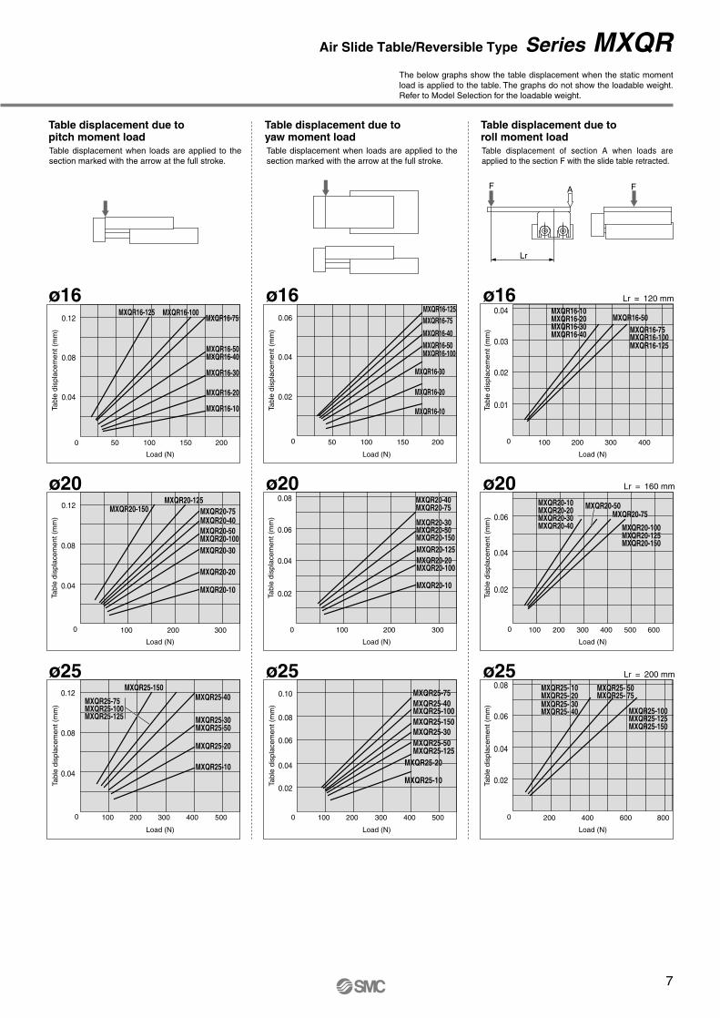
The below graphs show the table displacement when the static moment load is applied to the table. The graphs do not show the loadable weight. Refer to Model Selection for the loadable weight.
Table displacement due topitch moment loadTable displacement when loads are applied to the section marked with the arrow at the full stroke.
Table displacement due toyaw moment loadTable displacement when loads are applied to the section marked with the arrow at the full stroke.
Table displacement due toroll moment loadTable displacement of section A when loads are applied to the section F with the slide table retracted.
7
Air Slide Table/Reversible Type Series MXQR

ø7
5.75
11.5 4.5
4
20 16 13
11.5 4.5
3.5
ø7ø6
ZZ
Z
K 12.5
3 6.5
1.5
3114 2712
1
(NN-1) x H
4
HA GA
H
G
20
13.5
1
F
0.5
11
4
9
10
20
5.5
32 6
3 J I
1215
5.5 3
18.2
0.3
M5
NN x M4 x 0.7Tapped through hole
-1 x F2N
N x M3 x 0.5 thread depth 4ø3 depth 2.5+0.03
0
ø3
dept
h 2.
5+
0.03
0
A
A
B
B
4 x M2.5 x 0.45 thread depth 3.5
4 x M2.5 x 0.45 thread depth 2.5
2 x M2.5 x 0.45 thread depth 3
Pilot port 2 x M5 x 0.8
3 x M3 x 0.5 thread depth 5
3H9
de
pth
2.5
+0.
025
0
ø3H9 depth 2.5+0.025 0
Dimensions: MXQR 6
Model F2225212627
N44666
G 613—1121
H2326—2828
NN22333
I 999
169
J1727374865
K21.531.541.551.561.5
Z41.551.561.579.589.5
M4252628090
ZZ4858688696
MXQR6-10MXQR6-20MXQR6-30MXQR6-40MXQR6-50
Section AA Section BB
(mm)
GA1313293949
HA1626202828
Bottom view of MXQR6-30
Note) Note)
Note) Refer to the bottom view of the MXQR6-30.
Mounting of adjuster on the right side
∗ For detailed dimensions about the stroke adjuster, refer to Adjuster Options.Rubber stopper (Refer to pages 20 and 21.)Shock absorber (Refer to page 22.)Metal stopper (Refer to pages 23 and 24.)
Note 1) If long bolts are used, they can touch the guide block and cause malfunction, etc.Refer to Specific Product Precautions.
Note 2) Since the table is made of a magnetic substance, it could become magnetized if touched by a magnet, etc. This could cause auto switch malfunction.
Note 3) Check the procedures and tightening torque when changing the mounting position of the adjuster on site. Otherwise, operation failure, accuracy failure, play and damage can result. For details, refer to the MXQR Operation Manual.
8
Series MXQR

Retraction stroke endshock absorber
Extension stroke end shock absorber
Extension stroke end metal stopper
Retraction stroke endmetal stopper
Retraction stroke endrubber stopper
Extension stroke end rubber stopper
76
19.5
18
Max. 226Max. 13 19.5
Max. 10
Max. 10
6
19.5
17.5
6 19.5
19.5
17.5
6 19.5
ø3H9 depth 2.5+0.025 0
3H9
de
pth
2.5
+0.
025
0
12
1.5
20
20 16 134
HA GA
ZZ
3127
13.5 12
15
5.5 3
Bottom view of MXQR6-30
Bottom view
Mounting of adjuster on the left side∗ Other dimensions are the same as those for
mounting the adjuster on the right side.
Note 1) If long bolts are used, they can touch the guide block and cause malfunction, etc. Refer to Specific Product Precautions.
Note 2) Since the table is made of a magnetic substance, it could become magnetized if touched by a magnet, etc. This could cause auto switch malfunction.
Note 3) Check the procedures and tightening torque when changing the mounting position of the adjuster on site. Otherwise, operation failure, accuracy failure, play and damage can result. For details, refer to the MXQR Operation Manual.
Extension stroke end5
Retraction stroke end5
Stroke Adjustable Range
∗ Other dimensions are the same as those for mounting the adjuster on the right side.
Extension stroke end12
Retraction stroke end12
Stroke Adjustable Range
∗ Other dimensions are the same as those for mounting the adjuster on the right side.
Extension stroke end5
Retraction stroke end5
Stroke Adjustable Range
(mm)
(mm)
(mm)
∗ Other dimensions are the same as those for mounting the adjuster on the right side.
With rubber stopper (ø6): MXQR6(L)-��AS, AT, A
With metal stopper (ø6): MXQR6(L)-��CS, CT, C
With shock absorber (ø6): MXQR6(L)-��BS, BT, B
Adjuster Options
9
Air Slide Table/Reversible Type Series MXQR

ø7
6.75
27 23 6
4
(NN-1) x H
4
KA
K
14.6
73.8
14.6
73.8
16
132 36
4
13.5 4.7
ø6.
5
13.5 4.7
6.5
3.5
2 716
1
F
12
0.7
12
24
GAHA
GH
ø7
1421
.20.
3
23
M6
ZZZ
J I3.5
6.5 3.5
1715
10
5
N x M3 x 0.5 thread depth 4.5
NN x M4 x 0.7 tapped through hole
A
A B
B
NA x M3 x 0.5 thread depth 3.5
Pilot port 2 x M5 x 0.82 x M3 x 0.5 thread depth 4
4 x M3 x 0.5 thread depth 4
3 x M4 x 0.7 thread depth 6
ø3 depth 3+0.03 0
ø3
dept
h 3
+0.
03 0
-1 x F2N
ø3H9 depth 3+0.025 0
3H9
de
pth
3+
0.02
5 0
Section AA Section BB
Bottom view of MXQR8-30
Dimensions: MXQR 8
Model F252526324650
N446666
G 714— 8 831
H2528—312930
NN223344
I111012141312
J 1728405278
105
K23.533.543.553.563.588.5
Z 45.5 55.5 69.5 83.5108.5134.5
M 46 56 70 84109135
ZZ 53 63 77 91116142
MXQR8-10MXQR8-20MXQR8-30MXQR8-40MXQR8-50MXQR8-75
Mounting of adjuster on the right side
(mm)
GA131429393761
HA192827315860
NA444488
KA————
82.5112.5
Note)
Note) Refer to the bottom view of the MXQR8-30.
Note)
∗ For detailed dimensions about the stroke adjuster, refer to Adjuster Options.Rubber stopper (Refer to pages 20 and 21.)Shock absorber (Refer to page 22.)Metal stopper (Refer to pages 23 and 24.)
Note 1) If long bolts are used, they can touch the guide block and cause malfunction, etc.Refer to Specific Product Precautions.
Note 2) Since the table is made of a magnetic substance, it could become magnetized if touched by a magnet, etc. This could cause auto switch malfunction.
Note 3) Check the procedures and tightening torque when changing the mounting position of the adjuster on site. Otherwise, operation failure, accuracy failure, play and damage can result. For details, refer to the MXQR Operation Manual.
10
Series MXQR
A

21
22.5
6.5
22.5Max. 98
22.5
6.5
21
22.5Max. 118
Retraction stroke endmetal stopper
Extension stroke end metal stopper
Retraction stroke endrubber stopper
Extension stroke end rubber stopper
Extension stroke end shock absorber
Retraction stroke endshock absorber
8Max. 23 Max. 3225
11.5
2522
1
24
ø3H9 depth 3+0.025 0
ø3H
9
dep
th 3
+0.
025
0
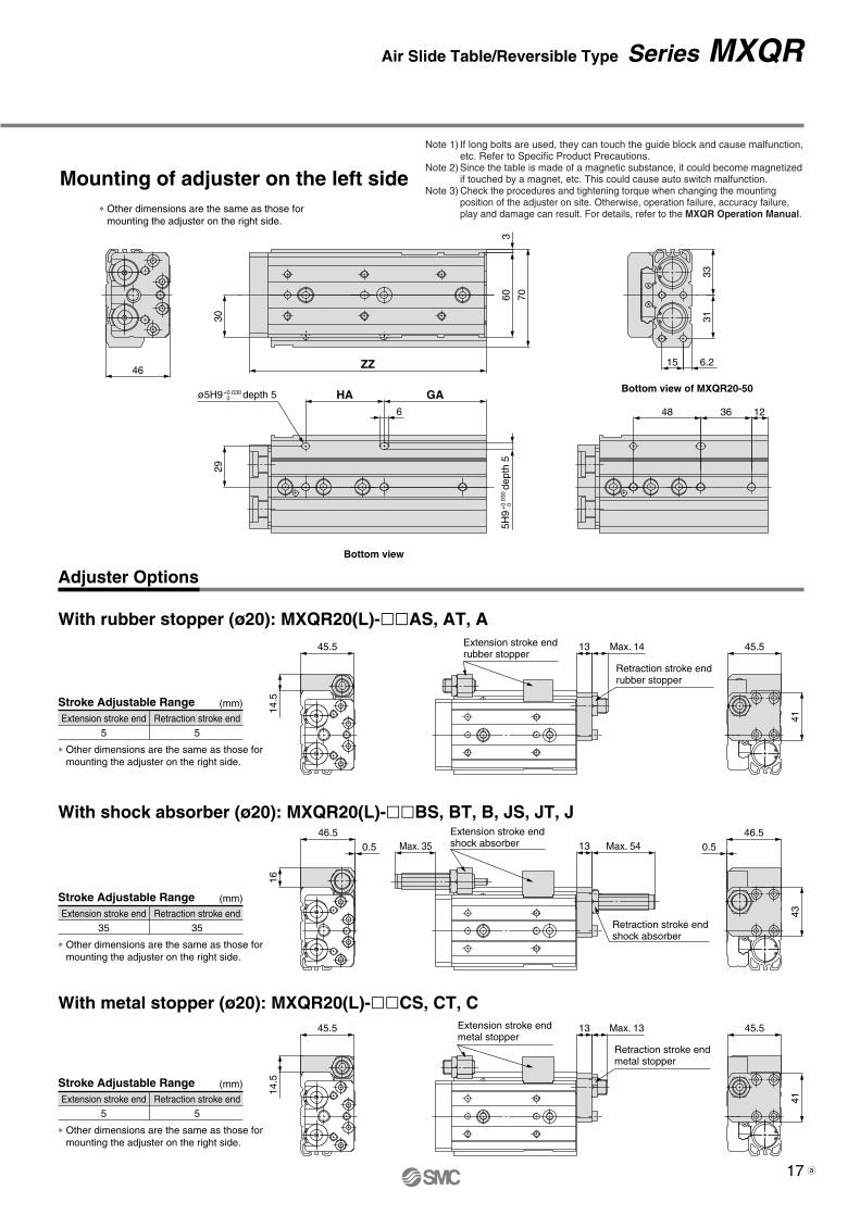
Mounting of adjuster on the left side
Note 1) If long bolts are used, they can touch the guide block and cause malfunction, etc. Refer to Specific Product Precautions.
Note 2) Since the table is made of a magnetic substance, it could become magnetized if touched by a magnet, etc. This could cause auto switch malfunction.
Note 3) Check the procedures and tightening torque when changing the mounting position of the adjuster on site. Otherwise, operation failure, accuracy failure, play and damage can result. For details, refer to the MXQR Operation Manual.
16
132
14
4
HA GA
ZZ23
36
6.5 3.5
1715
27 623Bottom view of MXQR8-30
Bottom view
∗ Other dimensions are the same as those for mounting the adjuster on the right side.
With rubber stopper (ø8): MXQR8(L)-��AS, AT, A
With metal stopper (ø8): MXQR8(L)-��CS, CT, C
With shock absorber (ø8): MXQR8(L)-��BS, BT, B, JS, JT, J
Adjuster Options
Extension stroke end5
Retraction stroke end5
Stroke Adjustable Range
∗ Other dimensions are the same as those for mounting the adjuster on the right side.
(mm)
Extension stroke end5
Retraction stroke end5
Stroke Adjustable Range (mm)
∗ Other dimensions are the same as those for mounting the adjuster on the right side.
Extension stroke end20
Retraction stroke end20
Stroke Adjustable Range
∗ Other dimensions are the same as those for mounting the adjuster on the right side.
(mm)
11
Air Slide Table/Reversible Type Series MXQR
a
ø9
29
4.8
30
M8
KA 18.5
8.55K 18.5
8.55
ZZZ
8 4.7
2.5
39 29 9
5
(NN-1) x H
8.7
84.
7
2 9.5
20 39 46
17.4 6.617.4 6.6
2220
19.5
1
F
1
16
5
14.5
GA
G
HA
H
19
ø9ø8.
5
0.3
27.2
IJ4.75
5
13
N x M4 x 0.7 thread depth 5
B
B
A
A NN x M5 x 0.8Tapped through hole
NA x M4 x 0.7 thread depth 4
2 x M4 x 0.7 thread depth 6
Pilot port 2 x M5 x 0.8
4 x M4 x 0.7 thread depth 6
3 x M5 x 0.8 thread depth 8
ø4H9 depth 4+0.030 0
4H9
de
pth
4+
0.03
0 0
-1 x F2N
ø4H9 depth 4+0.030 0
4H9
de
pth
4+
0.03
0 0
Section AA Section BB
Bottom view of MXQR12-40
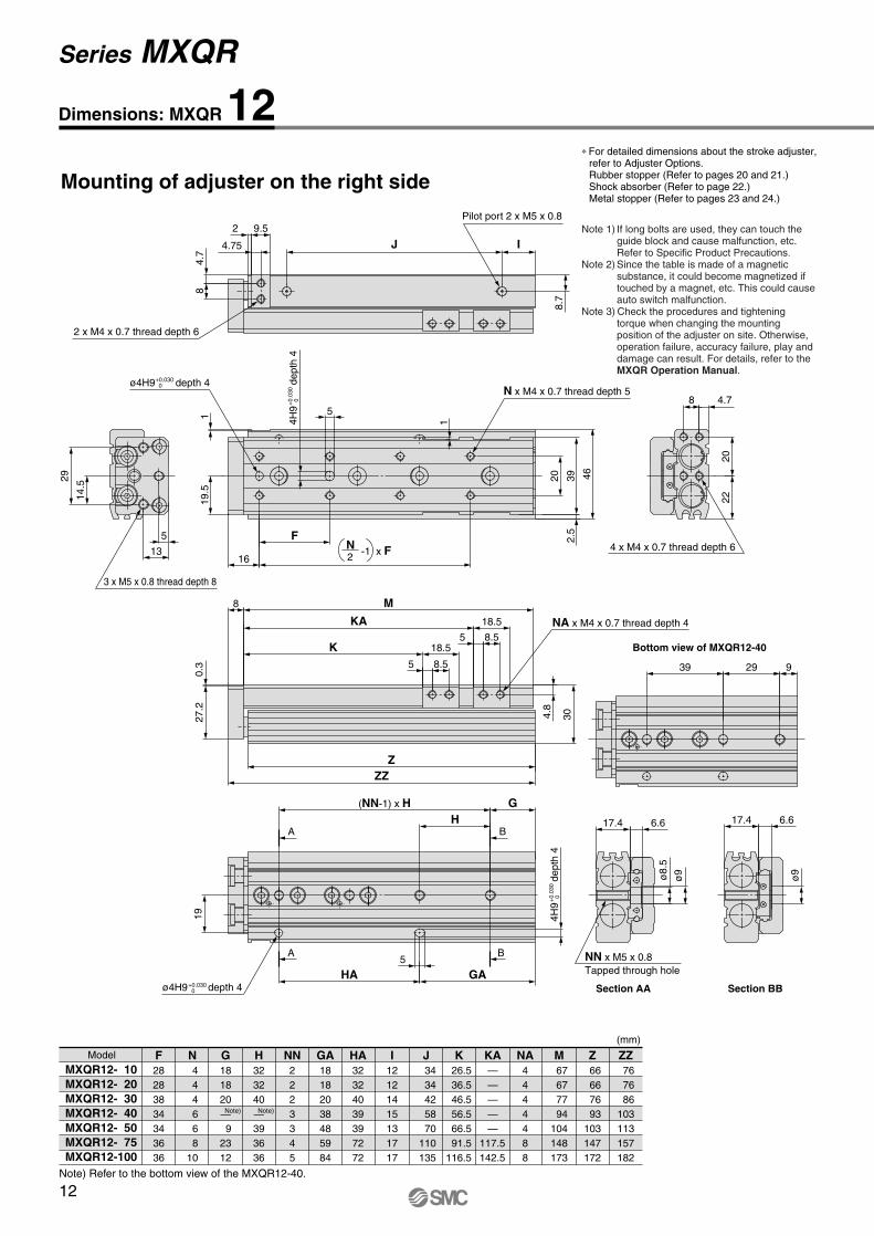
Dimensions: MXQR 12
Model F28283834343636
N 4 4 4 6 6 810
G181820— 92312
H323240—393636
NN2223345
I12121415131717
J 3434425870
110135
K 26.5 36.5 46.5 56.5 66.5 91.5116.5
Z 66 66 76 93103147172
M 67 67 77 94104148173
ZZ 76 76 86103113157182
MXQR12- 10MXQR12- 20MXQR12- 30MXQR12- 40MXQR12- 50MXQR12- 75MXQR12-100
(mm)
GA18182038485984
HA32324039397272
NA4444488
KA—————
117.5142.5
Note)
Note) Refer to the bottom view of the MXQR12-40.
Note)
Mounting of adjuster on the right side
∗ For detailed dimensions about the stroke adjuster, refer to Adjuster Options.Rubber stopper (Refer to pages 20 and 21.)Shock absorber (Refer to page 22.)Metal stopper (Refer to pages 23 and 24.)
Note 1) If long bolts are used, they can touch the guide block and cause malfunction, etc.Refer to Specific Product Precautions.
Note 2) Since the table is made of a magnetic substance, it could become magnetized if touched by a magnet, etc. This could cause auto switch malfunction.
Note 3) Check the procedures and tightening torque when changing the mounting position of the adjuster on site. Otherwise, operation failure, accuracy failure, play and damage can result. For details, refer to the MXQR Operation Manual.
12
Series MXQR

10
10
Max. 18 Max. 30
10
29.5
28
29.5
10
29.5
28
29.5Max. 13
Retraction stroke endrubber stopper
Extension stroke end rubber stopper
Retraction stroke endshock absorber
Extension stroke end shock absorber
10
10
29.5
28
29.5Max. 11Extension stroke end metal stopper
Retraction stroke endmetal stopper
ø4H9 depth 4+0.030 0
4H9
de
pth
4+
0.03
0 0
Bottom view of MXQR12-40
8
2.5
19
HA
5
GA
39 29 9
4.7
2022
30 ZZ
39 46
19.5
Mounting of adjuster on the left side∗ Other dimensions are the same as those for
mounting the adjuster on the right side.
Bottom view
With rubber stopper (ø12): MXQR12(L)-��AS, AT, A
With metal stopper (ø12): MXQR12(L)-��CS, CT, C
With shock absorber (ø12): MXQR12(L)-��BS, BT, B, JS, JT, J
Adjuster Options
Note 1) If long bolts are used, they can touch the guide block and cause malfunction, etc. Refer to Specific Product Precautions.
Note 2) Since the table is made of a magnetic substance, it could become magnetized if touched by a magnet, etc. This could cause auto switch malfunction.
Note 3) Check the procedures and tightening torque when changing the mounting position of the adjuster on site. Otherwise, operation failure, accuracy failure, play and damage can result. For details, refer to the MXQR Operation Manual.
Extension stroke end5
Retraction stroke end5
Stroke Adjustable Range
∗ Other dimensions are the same as those for mounting the adjuster on the right side.
(mm)
Extension stroke end5
Retraction stroke end5
Stroke Adjustable Range (mm)
∗ Other dimensions are the same as those for mounting the adjuster on the right side.
Extension stroke end18
Retraction stroke end18
Stroke Adjustable Range
∗ Other dimensions are the same as those for mounting the adjuster on the right side.
(mm)
13
Air Slide Table/Reversible Type Series MXQR

6.5
ø10
.5
22.4 7.6
ø10
.5
22.4 7.6
11.2
(NN-1) x H
45 35 13
5.711
3.5
24 49 58
115.
7113
5.5
KA
K
21
105.5
21
105.5
24.514
.5
1
29
GAHA
H
24
G
M
ZZZ
F
1
IJ
2824
.5
ø9.
5
6
3733.7
0.3
10
6
21
5.5
14
B
B
A
N x M5 x 0.8 thread depth 6
4 x M5 x 0.8 thread depth 7
NN x M6 x 1Tapped through hole
2 x M5 x 0.8 thread depth 8
Pilot port 2 x M5 x 0.8
NA x M5 x 0.8 thread depth 6.5
A
3 x M6 x 1 thread depth 10
ø5H9 depth 5+0.030 0
5H9
de
pth
5+
0.03
0 0
ø5H9 depth 5+0.030 0
5H9
de
pth
5+
0.03
0 0
-1 x F2N
Section AA Section BB
Bottom view of MXQR16-50
Dimensions: MXQR 16
Model F3838485840464444
N 4 4 4 4 6 6 810
G18181919—213617
H39394858—524444
NN22223345
I1212121220151823
J 40
40 50 60 68105145165
K 28 38 48 58 68 93118143
Z 77 77 87 97113145188213
M 78 78 88 98114146189214
ZZ 89 89 99109125157200225
MXQR16- 10MXQR16- 20MXQR16- 30MXQR16- 40MXQR16- 50MXQR16- 75MXQR16-100MXQR16-125
Mounting of adjuster on the right side
(mm)
GA 18 18 19 19 48 73 80105
HA3939485845528888
NA44448888
KA————
91123166191
Note)
Note) Refer to the bottom view of the MXQR16-50.
Note)
∗ For detailed dimensions about the stroke adjuster, refer to Adjuster Options.Rubber stopper (Refer to pages 20 and 21.)Shock absorber (Refer to pages 22.)Metal stopper (Refer to pages 23 and 24.)
Note 1) If long bolts are used, they can touch the guide block and cause malfunction, etc.Refer to Specific Product Precautions.
Note 2) Since the table is made of a magnetic substance, it could become magnetized if touched by a magnet, etc. This could cause auto switch malfunction.
Note 3) Check the procedures and tightening torque when changing the mounting position of the adjuster on site. Otherwise, operation failure, accuracy failure, play and damage can result. For details, refer to the MXQR Operation Manual.
14
Series MXQR

Max. 20 Max. 34
33.5
36.512
12.5
36.5
Max. 10
33.5
36.512
12.5
36.5
36.5
12.5
33.5
36.512
Extension stroke end shock absorber
Retraction stroke endshock absorber
Extension stroke end metal stopper
Retraction stroke endmetal stopper
ø5H9 depth 5+0.030 0
5H9
dept
h 5
+0.
030
0
Retraction stroke endrubber stopper
Extension stroke end rubber stopper
Max. 12
Mounting of adjuster on the left side∗ Other dimensions are the same as those for
mounting the adjuster on the right side.
3.5
37
45 35 13
ZZ
24
HA GA6
5.711
49 58
24.5
2824
.5
Bottom view of MXQR16-50
Bottom view
With rubber stopper (ø16): MXQR16(L)-��AS, AT, A
With metal stopper (ø16): MXQR16(L)-��CS, CT, C
With shock absorber (ø16): MXQR16(L)-��BS, BT, B, JS, JT, J
Adjuster Options
Note 1) If long bolts are used, they can touch the guide block and cause malfunction, etc. Refer to Specific Product Precautions.
Note 2) Since the table is made of a magnetic substance, it could become magnetized if touched by a magnet, etc. This could cause auto switch malfunction.
Note 3) Check the procedures and tightening torque when changing the mounting position of the adjuster on site. Otherwise, operation failure, accuracy failure, play and damage can result. For details, refer to the MXQR Operation Manual.
Extension stroke end5
Retraction stroke end5
Stroke Adjustable Range
∗ Other dimensions are the same as those for mounting the adjuster on the right side.
(mm)
Extension stroke end22
Retraction stroke end22
Stroke Adjustable Range
∗ Other dimensions are the same as those for mounting the adjuster on the right side.
(mm)
Extension stroke end5
Retraction stroke end5
Stroke Adjustable Range (mm)
∗ Other dimensions are the same as those for mounting the adjuster on the right side.
15
Air Slide Table/Reversible Type Series MXQR

ø11
27.4 9.1 27.4 9.1
48 36 12
(NN-1) x H
360
2.5 13
30 70
KA
K
6.5
25
6.5 12
25
126.5
ø9.
5
ø11
15 6.2
3133
13.4
7
13.7
3017.5
1.5
35
29
GH
HA GA
ZZZ
M
1.5
F
IJ
6
13
41.5
0.5
46
27
6
6.5
7
18
B
B
N x M5 x 0.8 thread depth 8
2 x M6 x 1 thread depth 7Pilot port 2 x Rc1/8
NA x M6 x 1 thread depth 6
A
A
4 x M5 x 0.8 thread depth 8
NN x M6 x 1Tapped through hole
3 x M6 x 1 thread depth 13
ø5H9 depth 5+0.030 0
5H9
de
pth
5+
0.03
0 0
-1 x F2N
5H9
de
pth
5+
0.03
0 0
ø5H9 depth 5+0.030 0
Section AA Section BB
Bottom view of MXQR20-50
Dimensions: MXQR 20
Model F454048584255505562
N444466888
G22222222—17183756
H46464656—56565962
NN222233444
I161616161823251821
J 46
46 46 56 72100155190215
K 31 41 51 61 71 96121146171
Z 92.5 92.5 92.5102.5120.5153.5210.5238.5266.5
M 94 94 94104122155212240268
ZZ108108108118136169226254282
MXQR20- 10MXQR20- 20MXQR20- 30MXQR20- 40MXQR20- 50MXQR20- 75MXQR20-100MXQR20-125MXQR20-150
(mm)
GA 18 18 18 22 48 73 74 96118
HA 50 50 50 56 48 56112118124
NA444448888
KA—————
126183211239
Note)
Note) Refer to the bottom view of the MXQR20-50.
Note)
Mounting of adjuster on the right side
∗ For detailed dimensions about the stroke adjuster, refer to Adjuster Options.Rubber stopper (Refer to pages 20 and 21.)Shock absorber (Refer to page 22.)Metal stopper (Refer to pages 23 and 24.)
Note 1) If long bolts are used, they can touch the guide block and cause malfunction, etc.Refer to Specific Product Precautions.
Note 2) Since the table is made of a magnetic substance, it could become magnetized if touched by a magnet, etc. This could cause auto switch malfunction.
Note 3) Check the procedures and tightening torque when changing the mounting position of the adjuster on site. Otherwise, operation failure, accuracy failure, play and damage can result. For details, refer to the MXQR Operation Manual.
16
Series MXQR
46.50.50.5
43
46.5Max. 35 Max. 54
16
13
41
45.545.5
14.5
Max. 1313
41
45.545.5
14.5
Max. 1413
Retraction stroke endshock absorber
Extension stroke end shock absorber
Retraction stroke endmetal stopper
Extension stroke end metal stopper
Retraction stroke endrubber stopper
Extension stroke end rubber stopper
ø5H9 depth 5+0.030 0
5H9
de
pth
5+
0.03
0 0
360 70
29
HA GA6 48 36 12
46 ZZ 15 6.2
3133
30
Mounting of adjuster on the left side∗ Other dimensions are the same as those for
mounting the adjuster on the right side.
Bottom view of MXQR20-50
Bottom view
With rubber stopper (ø20): MXQR20(L)-��AS, AT, A
With metal stopper (ø20): MXQR20(L)-��CS, CT, C
With shock absorber (ø20): MXQR20(L)-��BS, BT, B, JS, JT, J
Adjuster Options
Note 1) If long bolts are used, they can touch the guide block and cause malfunction, etc. Refer to Specific Product Precautions.
Note 2) Since the table is made of a magnetic substance, it could become magnetized if touched by a magnet, etc. This could cause auto switch malfunction.
Note 3) Check the procedures and tightening torque when changing the mounting position of the adjuster on site. Otherwise, operation failure, accuracy failure, play and damage can result. For details, refer to the MXQR Operation Manual.
Extension stroke end5
Retraction stroke end5
Stroke Adjustable Range
∗ Other dimensions are the same as those for mounting the adjuster on the right side.
(mm)
Extension stroke end35
Retraction stroke end35
Stroke Adjustable Range
∗ Other dimensions are the same as those for mounting the adjuster on the right side.
(mm)
Extension stroke end5
Retraction stroke end5
Stroke Adjustable Range
∗ Other dimensions are the same as those for mounting the adjuster on the right side.
(mm)
17
Air Slide Table/Reversible Type Series MXQR
a

ø12
16.7
3840
65 2250
44
22
21.5
6.5
(NN-1) x H
8
KKA 31
15831
158
3
36 74 84
33.4 10.133.4 10.1
ø12
ø11
20 6.7
16416
8.7
371.
5
1.5
HG
HA
35
GA
ZZZ
M
F
30
IJ8
7
5549.5
0.5
15
7
B
B
NA x M8 x 1.25 thread depth 8
N x M6 x 1 thread depth 11
2 x M8 x 1.25 thread depth 9
A
A
4 x M6 x 1 thread depth 10
NN x M8 x 1.25Tapped through hole
3 x M8 x 1.25 thread depth 15
ø6H9 depth 6+0.030 0
6H9
de
pth
6+
0.03
0 0
Pilot port 2 x Rc1/8
-1 x F2N
ø6H9 depth 6+0.030 0
6H9
de
pth
6+
0.03
0 0
Section AA Section BB
Bottom view of MXQR25-75
Dimensions: MXQR 25
Model F554655657560486065
N444446888
G2323232332—443156
H5555556580—446666
NN222223444
I161616161631201818
J 56
56 56 66 90100150205230
K 35 45 55 65 75100125150175
Z105.5105.5105.5115.5139.5164.5203.5256.5281.5
M107107107117141166205258283
ZZ123123123133157182221274299
MXQR25- 10MXQR25- 20MXQR25- 30MXQR25- 40MXQR25- 50MXQR25- 75MXQR25-100MXQR25-125MXQR25-150
(mm)
GA 23 23 23 23 32 72 88 97122
HA 55 55 55 65 80 65 88132132
NA444444888
KA——————
170223248
Note)
Note) Refer to the bottom view of the MXQR25-75.
Note)
Mounting of adjuster on the right side
∗ For detailed dimensions about the stroke adjuster, refer to Adjuster Options.Rubber stopper (Refer to pages 20 and 21.)Shock absorber (Refer to page 22.)Metal stopper (Refer to pages 23 and 24.)
Note 1) If long bolts are used, they can touch the guide block and cause malfunction, etc.Refer to Specific Product Precautions.
Note 2) Since the table is made of a magnetic substance, it could become magnetized if touched by a magnet, etc. This could cause auto switch malfunction.
Note 3) Check the procedures and tightening torque when changing the mounting position of the adjuster on site. Otherwise, operation failure, accuracy failure, play and damage can result. For details, refer to the MXQR Operation Manual.
18
Series MXQR

16.5
49
54.5Max. 141554.5
16.5
49
54.5Max. 171554.5
Extension stroke end metal stopper
Retraction stroke endmetal stopper
Retraction stroke endrubber stopper
Extension stroke end rubber stopper
16.5
Max. 2954.5 Max. 52
49
54.515
Retraction stroke endshock absorber
Extension stroke end shock absorber
ø6H9 depth 6+0.030 0
6H9
de
pth
6+
0.03
0 0
374
4038
55 ZZ
84
20 6.7
37
HA
35
GA7
Mounting of adjuster on the left side∗ Other dimensions are the same as those for
mounting the adjuster on the right side.
Bottom view
Bottom view of MXQR25-75
With rubber stopper (ø25): MXQR25(L)-��AS, AT, A
With metal stopper (ø25): MXQR25(L)-��CS, CT, C
With shock absorber (ø25): MXQR25(L)-��BS, BT, B, JS, JT, J
Adjuster Options
Note 1) If long bolts are used, they can touch the guide block and cause malfunction, etc. Refer to Specific Product Precautions.
Note 2) Since the table is made of a magnetic substance, it could become magnetized if touched by a magnet, etc. This could cause auto switch malfunction.
Note 3) Check the procedures and tightening torque when changing the mounting position of the adjuster on site. Otherwise, operation failure, accuracy failure, play and damage can result. For details, refer to the MXQR Operation Manual.
Extension stroke end5
Retraction stroke end5
Stroke Adjustable Range
∗ Other dimensions are the same as those for mounting the adjuster on the right side.
(mm)
Extension stroke end35
Retraction stroke end35
Stroke Adjustable Range
∗ Other dimensions are the same as those for mounting the adjuster on the right side.
(mm)
Extension stroke end5
Retraction stroke end5
Stroke Adjustable Range
∗ Other dimensions are the same as those for mounting the adjuster on the right side.
(mm)
65 2250
19
Air Slide Table/Reversible Type Series MXQR

H
J
Q
K
AB
E
P
M
G
D
F
C
G
B
H E
A(C)
F
J
K
Extension stroke end
MXQR 6
MXQR 8
MXQR12
MXQR16
MXQR20
MXQR25
5
15
5
15
25
5
15
25
5
15
25
5
15
25
5
15
25
A
6
7
9.5
11
13
16
Retraction stroke end
MXQR 6
MXQR 8
MXQR12
MXQR16
MXQR20
MXQR25
5
15
5
15
25
5
15
25
5
15
25
5
15
25
5
15
25
B C F G M
M5 x 0.8
M6 x 1
M8 x 1
M10 x 1
M12 x 1.25
M14 x 1.5
P ∗1)
M2.5 x 6
M3 x 8
M4 x 12
M5 x 16
M6 x 16
M8 x 18
H J K Q ∗1)
M2.5 x 8
M3 x 10
M4 x 12
M5 x 16
M6 x 16
M8 x 18
16.5
26.5
19.5
29.5
39.5
23.5
33.5
43.5
24.5
34.5
44.5
27.5
37.5
47.5
32.5
42.5
52.5
D
A
17.5
21
28
33.5
41
49
B C F G H J K ∗1) E
M5 x 0.8
M6 x 1
M8 x 1
M10 x 1
M12 x 1.25
M14 x 1.5
M2.5 x 9
M3 x 11
M4 x 14
M5 x 18
M5 x 18
M6 x 22
Body mounting parts
Table mounting parts
E
19
22
29
36
45
54
8
9
14
17
20
22
7
7.5
11
13.5
16
18
7
8
12
14
17
19
2.5
3
4
5
6
6
12.5
14.6
18.5
21
25
31
6
7
10.5
13
16
17
8.3
9.8
12.7
15
18
20
∗1) Size of hexagon socket head bolt ∗2) Mounting the adjuster on the left side is also available. For “How to Order”, refer to page 3. The outer dimensions are the same as those for mounting the adjuster on the right side.
∗1) Size of hexagon socket head bolt ∗2) Mounting the adjuster on the left side is also available. For “How to Order”, refer to page 3. The outer dimensions are the same as those for mounting the adjuster on the right side.
19
22
29
35.5
44.5
53.5
8.5
11
14
17
18
21
16.5
26.5
19.5
29.5
39.5
23.5
33.5
43.5
24.5
34.5
44.5
27.5
37.5
47.5
32.5
42.5
52.5
6
8
10
12
13
15
7
8
12
14
17
19
2.5
3
4
5
6
6
Rubber stopper (AS, AT)
MXQR-AS 6
MXQR-AS 6-X11
MXQR-AS 8
MXQR-AS 8-X11
MXQR-AS 8-X12
MXQR-AS12
MXQR-AS12-X11
MXQR-AS12-X12
MXQR-AS16
MXQR-AS16-X11
MXQR-AS16-X12
MXQR-AS20
MXQR-AS20-X11
MXQR-AS20-X12
MXQR-AS25
MXQR-AS25-X11
MXQR-AS25-X12
MXQR-AT 6
MXQR-AT 6-X11
MXQR-AT 8
MXQR-AT 8-X11
MXQR-AT 8-X12
MXQR-AT12
MXQR-AT12-X11
MXQR-AT12-X12
MXQR-AT16
MXQR-AT16-X11
MXQR-AT16-X12
MXQR-AT20
MXQR-AT20-X11
MXQR-AT20-X12
MXQR-AT25
MXQR-AT25-X11
MXQR-AT25-X12
Model
MXQR 6MXQR 8MXQR12MXQR16MXQR20MXQR25
Tightening torque (N·m)
3.0
5.0
12.5
25.0
43.0
69.0
1. Do not replace with the bolt other than the original adjustment bolt.This could result in looseness and damage due to impact forces, etc.
2. Follow the table on the right for tightening torque of lock nuts.Insufficient torque will cause a de-crease in the positioning accuracy.
3. When stroke adjuster is adjusted, do not hit the table with the wrench.This could result in looseness.
Refer to the MXQR Operation Manual for details.
Caution for Adjuster Options
Dimensions: Adjuster
Applicablesize Model
Strokeadjustment range
(mm)
Body mounting parts Table mounting parts
Applicablesize Model
Strokeadjustment range
(mm)
Caution
20
Series MXQR
A

Applicable bore sizeAdjustment rangeNil
-X11-X12
MXQ
5 mm15 mm25 mm
6812162025
ø6 ø8ø12ø16ø20ø25
12 X11
MXQR 6
MXQR 8
MXQR12
MXQR16
MXQR20
MXQR25
MXQ-A627
MXQ-A627-X11
MXQ-A827
MXQ-A827-X11
MXQ-A827-X12
MXQ-A1227
MXQ-A1227-X11
MXQ-A1227-X12
MXQ-A1627
MXQ-A1627-X11
MXQ-A1627-X12
MXQ-A2027
MXQ-A2027-X11
MXQ-A2027-X12
MXQ-A2527
MXQ-A2527-X11
MXQ-A2527-X12
5
15
5
15
25
5
15
25
5
15
25
5
15
25
5
15
25
A B
2.5
3
4
5
6
6
C
716.5
26.5
19.5
29.5
39.5
23.5
33.5
43.5
24.5
34.5
44.5
27.5
37.5
47.5
32.5
42.5
52.5
8
12
14
17
19
MD
3
3.5
4
4
5
6
M5 x 0.8
M6 x 1
M8 x 1
M10 x 1
M12 x 1.25
M14 x 1.5
A 27
B D C
A
M
Dimensions: Adjustment Bolt/Rubber Stopper
Applicablesize
ModelStroke
adjustment range(mm)
How to Order Adjustment Bolt/Rubber Stopper
∗ -X12 (adjustment range: 25 mm) is not available with the MXQR6 series.∗ For dimensions, refer to the above figure. ∗ Mounting the adjuster on the left side is also the same.∗ Common with the MXQ series.
21
Air Slide Table/Reversible Type Series MXQR

MXQR-BT8MXQR-JT8
A
HH
B
GG
H
A
B
H
Body mounting parts Table mounting parts
MXQR-BS 8MXQR-BS12MXQR-BS16
MXQR-BS20MXQR-BS25 G
D
F
C
G
P
M
E E1
B
AQ
J
H
L
K
K
K
F
(C)
E E1
E E1
F
J
J
Extension stroke end
Applicable size
MXQR 6
MXQR 8
MXQR12
MXQR16
MXQR20
MXQR25
Model
MXQR-BS6
MXQR-BS8
MXQR-JS8
MXQR-BS12
MXQR-JS12
MXQR-BS16
MXQR-JS16
MXQR-BS20
MXQR-JS20
MXQR-BS25
MXQR-JS25
Strokeadjustment range
(mm)
Body mounting parts Table mounting parts
A
Retraction stroke end
B C F G M P ∗1) H J K Q ∗1) D E
∗1) Size of hexagon socket head bolt ∗2) Mounting the adjuster on the left side is also available. For “How to Order”, refer to page 3. The outer dimensions are the same as those for mounting the adjuster on the right side.
Shock absorber (BS, JS, BT, JT)
12
20
18
22
35
35
6
7
9.5
11
13
16
19
24.5
29
36
46
54
9
14
14
17
22
22
8
12.5
11
13.5
17.5
18
28.5
40.8
40.8
46.7
45.3
67.3
67.1
67.3
67.1
4
5
6
5
7
6
11
10
12
10
8
12
12
14
19
19
1
1.4
7
1.4
7
1.4
9
12
12
M6 x 0.75
M8 x 1
M8 x 1
M10 x 1
M14 x 1.5
M14 x 1.5
M2.5 x 6
M3 x 12
M4 x 12
M5 x 16
M6 x 18
M8 x 18
14.5
16.6
20.5
23
27
33
7
8
11
13.5
17
19
8.3
12
13
16
22
22
12.5
14.6
18.5
21
25
31
M2.5 x 8
M3 x 12
M4 x 12
M5 x 16
M6 x 20
M8 x 20
LE1
Applicable size
MXQR 6
MXQR 8
MXQR12
MXQR16
MXQR20
MXQR25
Model
MXQR-BT6
MXQR-BT8
MXQR-JT8
MXQR-BT12
MXQR-JT12
MXQR-BT16
MXQR-JT16
MXQR-BT20
MXQR-JT20
MXQR-BT25
MXQR-JT25
Strokeadjustment range
(mm)A B C F G H J K ∗1) E
12
20
18
22
35
35
18
24
28
33.5
43
49
19
24.5
29
35.5
46
53.5
8.5
—
14
17
18
21
28.5
40.8
40.8
46.7
45.3
67.3
67.1
67.3
67.1
4
5
6
5
7
6
11
10
12
10
6
8
10
12
13
15
8
12
12
14
19
19
1
1.4
7
1.4
7
1.4
9
12
12
M6 x 0.75
M8 x 1
M8 x 1
M10 x 1
M14 x 1.5
M14 x 1.5
M2.5 x 9
M3 x 11
M4 x 14
M5 x 18
M5 x 18
M6 x 22
E1
ModelMXQR 6MXQR 8MXQR12
Tightening torque (N·m)0.85
1.67
Model Tightening torque (N·m)3.14
10.8MXQR20MXQR25
MXQR16
∗1) Size of hexagon socket head bolt∗2) Mounting the adjuster on the left
side is also available.For “How to Order”, refer to page 3.The outer dimensions are the same as those for mounting the adjuster on the right side.
1. Follow the table on the right for lock nut tightening torque of shock absorber.
2. For the details of handling the shock absorber, refer to the catalog and Operation Manual of the shock absorber.
Caution for Adjuster Options
Dimensions: Adjuster
Caution
22
Series MXQR
A

Extension stroke end
MXQR 6
MXQR 8
MXQR12
MXQR16
MXQR20
MXQR25
5
15
5
15
25
5
15
25
5
15
25
5
15
25
5
15
25
A
6
7
9.5
11
13
16
Retraction stroke end
Applicablesize
MXQR 6
MXQR 8
MXQR12
MXQR16
MXQR20
MXQR25
Model
5
15
5
15
25
5
15
25
5
15
25
5
15
25
5
15
25
Strokeadjustment range
(mm)
B C F G M
M5 x 0.8
M6 x 1
M8 x 1
M10 x 1
M12 x 1.25
M14 x 1.5
P ∗1)
M2.5 x 6
M3 x 8
M4 x 12
M5 x 16
M6 x 16
M8 x 18
H J K Q ∗1)
M2.5 x 8
M3 x 10
M4 x 12
M5 x 16
M6 x 20
M8 x 20
15.5
25.5
18
28
38
22
32
42
23
33
43
27
37
47
30
40
50
D
A
17.5
21
28
33.5
41
49
B C F G H J K ∗1) E
M5 x 0.8
M6 x 1
M8 x 1
M10 x 1
M12 x 1.25
M14 x 1.5
M2.5 x 9
M3 x 11
M4 x 14
M5 x 18
M5 x 18
M6 x 22
Body mounting parts
Table mounting parts
E
19
22
29
36
45
54
8
9
14
17
20
22
7
7.5
11
13.5
16
18
7
8
12
14
17
19
2.5
3
4
5
6
6
14.5
16.6
20.5
23
27
33
7
8
11
13.5
17
19
8.3
9.8
13
16
22
22
19
22
29
35.5
44.5
53.5
8.5
11
14
17
18
21
15.5
25.5
18
28
38
22
32
42
23
33
43
27
37
47
30
40
50
6
8
10
12
13
15
7
8
12
14
17
19
2.5
3
4
5
6
6
Metal stopper (CS, CT)
L
12.5
14.6
18.5
21
25
31
AB
E
P
M
G
D
F
C
Q
J
H
L
K
∗1) Size of hexagon socket head bolt∗2) Mounting the adjuster on the left side is also available.
For “How to Order”, refer to page 3. The outer dimensions are the same as those for mounting the adjuster on the right side.
∗1) Size of hexagon socket head bolt∗2) Mounting the adjuster on the left side is also available.
For “How to Order”, refer to page 3. The outer dimensions are the same as those for mounting the adjuster on the right side.
E
G
B
H
A(C)
F
MXQR-CS 6
MXQR-CS 6-X11
MXQR-CS 8
MXQR-CS 8-X11
MXQR-CS 8-X12
MXQR-CS12
MXQR-CS12-X11
MXQR-CS12-X12
MXQR-CS16
MXQR-CS16-X11
MXQR-CS16-X12
MXQR-CS20
MXQR-CS20-X11
MXQR-CS20-X12
MXQR-CS25
MXQR-CS25-X11
MXQR-CS25-X12
MXQR-CT 6
MXQR-CT 6-X11
MXQR-CT 8
MXQR-CT 8-X11
MXQR-CT 8-X12
MXQR-CT12
MXQR-CT12-X11
MXQR-CT12-X12
MXQR-CT16
MXQR-CT16-X11
MXQR-CT16-X12
MXQR-CT20
MXQR-CT20-X11
MXQR-CT20-X12
MXQR-CT25
MXQR-CT25-X11
MXQR-CT25-X12
J
Dimensions: Adjuster
Body mounting parts Table mounting partsApplicablesize
ModelStroke
adjustment range(mm)
K
23
Air Slide Table/Reversible Type Series MXQR
A
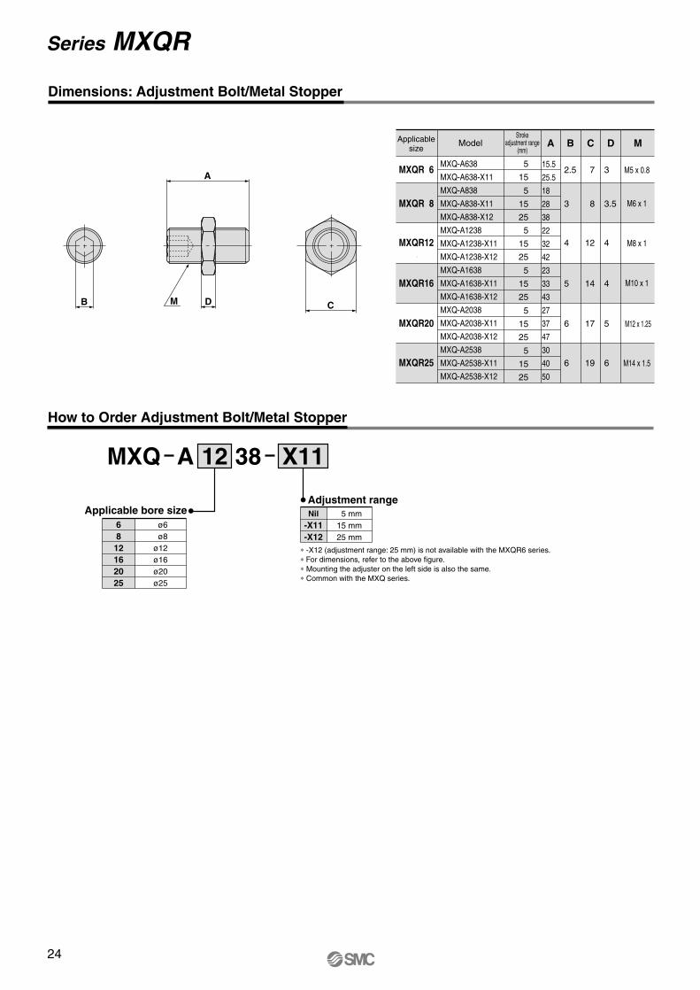
Applicable bore sizeAdjustment rangeNil
-X11-X12
MXQ
5 mm15 mm25 mm
6812162025
ø6 ø8ø12ø16ø20ø25
12 X11
MXQR 6
MXQR 8
MXQR12
MXQR16
MXQR20
MXQR25
MXQ-A638
MXQ-A638-X11
MXQ-A838
MXQ-A838-X11
MXQ-A838-X12
MXQ-A1238
MXQ-A1238-X11
MXQ-A1238-X12
MXQ-A1638
MXQ-A1638-X11
MXQ-A1638-X12
MXQ-A2038
MXQ-A2038-X11
MXQ-A2038-X12
MXQ-A2538
MXQ-A2538-X11
MXQ-A2538-X12
5
15
5
15
25
5
15
25
5
15
25
5
15
25
5
15
25
A B
2.5
3
4
5
6
6
C
715.5
25.5
18
28
38
22
32
42
23
33
43
27
37
47
30
40
50
8
12
14
17
19
MD
3
3.5
4
4
5
6
M5 x 0.8
M6 x 1
M8 x 1
M10 x 1
M12 x 1.25
M14 x 1.5
A 38
∗ -X12 (adjustment range: 25 mm) is not available with the MXQR6 series.∗ For dimensions, refer to the above figure. ∗ Mounting the adjuster on the left side is also the same.∗ Common with the MXQ series.
C
A
DMB
Dimensions: Adjustment Bolt/Metal Stopper
Applicablesize
ModelStroke
adjustment range(mm)
How to Order Adjustment Bolt/Metal Stopper
24
Series MXQR

Replacement Parts/Seal Kit
68
12162025
Bore size (mm) Kit no.
MXQ 6-PSMXQ 8-PSMXQ12-PSMXQ16-PSMXQ20-PSMXQ25-PS
Contents
Replacement Parts/Grease Pack
Guide unit
Cylinder unit
Applied part Grease pack part no.
GR-S-010 (10 g)GR-S-020 (20 g)
GR-L-005 (5 g)GR-L-010 (10 g)
Set of nos. above to (1 set)
∗ Seal kit includes these seals to provide as a set. Order the seal kit, based on each bore size.
Construction
No.123456
DescriptionBodyTable End plateGuide blockCoverReturn guideScraperRodPiston assembly Rod coverSeal supportHead capFloating bushingRod bumperEnd bumperSteel ballSpring pinPiston sealRod sealO-ring
7891011121314151617181920
Aluminum alloyStainless steelAluminum alloyStainless steelSynthetic resinSynthetic resin
Stainless steel, NBRStainless steel
—Aluminum alloy
BrassSynthetic resinStainless steelPolyurethanePolyurethane
High carbon chrome bearing steel
Stainless steelNBRNBRNBR
MaterialHard anodizedHeat treated
Hard anodizedHeat treated
With magnet on single side
AnodizedElectroless nickel plated
Note
Component Parts
25
Air Slide Table/Reversible Type Series MXQR

A E B
Other than the applicable auto switches listed in “How to Order”, the following auto switches can be mounted.
∗ Normally closed (NC = b contact) solid state auto switches (D-F9G/F9H) and solid state auto switch (D-F8) are also available. Refer to Best Pneumatics No. 3 for details.
Auto Switch Proper Mounting Position (Detection at Stroke End)
Note) Adjust the auto switch after confirming the operating conditions in the actual setting. ( ): D-A93
Auto Switch Mounting
D-M9�, M9�VD-M9�W, M9�WVD-M9�A, M9�AVD-A9, A9�V
Operating Range (mm)
6
3
4.5
8
3
5
12
3.5
6
16
4.5
7
20
4.5
8
25
5.5
9
Applicable bore sizeAuto switch model
Operating Range
∗ Since the operating range is provided as a guideline including hysteresis, it cannot be guaranteed (assuming approximately ±30% dispersion). It may vary substantially depending on the ambient environment.
CautionAuto switch mounting tool
Tightening torque
D-A9�(V)D-M9�(V)D-M9�W(V)
Tightening Torque of Auto Switch Mounting Screw (N·m)
0.10 to 0.20
Tightening torqueAuto switch model
0.05 to 0.15
MXQR6
MXQR8
MXQR12
MXQR16
MXQR20
MXQR25
6
7.5
11.5
16.5
19
22
5.5
8
24.5
30.5
43.5
52.5
5.5
8
14.5
20.5
33.5
42.5
5.5
12
14.5
20.5
23.5
32.5
13.5
16
21.5
20.5
33.5
32.5
13.5
31
21.5
26.5
31.5
46.5
—
32
40.5
33.5
39.5
46.5
—
—
40.5
51.5
71.5
60.5
—
—
—
51.5
74.5
88.5
—
—
—
—
77.5
88.5
— —
—
—
—
—
—
—
—
—
Reed Auto Switch: D-A90, D-A93, D-A96, D-A90V, D-A93V, D-A96V
10 20 30 12575 100
Stroke
BStroke
EModel A
40 50 150 10
20 30 12575 10040 50 150
MXQR6
MXQR8
MXQR12
MXQR16
MXQR20
MXQR25
10
11.5
15.5
20.5
23
27
Solid State Auto Switch: D-M9B, D-M9N, D-M9P, D-M9BW, D-M9NW, D-M9PW, D-M9�A
10
9.5
12
28.5
34.5
47.5
56.5
20
9.5
12
18.5
24.5
37.5
46.5
9.5
16
18.5
24.5
27.5
36.5
17.5
20
25.5
24.5
37.5
36.5
17.5
35
25.5
30.5
35.5
50.5
—
36
44.5
37.5
43.5
50.5
—
—
44.5
55.5
75.5
64.5
—
—
—
55.5
78.5
92.5
—
—
—
—
81.5
92.5
30 12575 100
Stroke
BStroke
EModel A
40 50 150 10 20 30 12575 10040 50 150
Solid State Auto Switch: D-M9BV, D-M9NV, D-M9PV, D-M9BWV, D-M9NWV, D-M9PWV, D-M9�AV
–0.5
3.5(1)6
(3.5)22.5(20)28.5(26)41.5(39)50.5(48)
3.5(1)6
(3.5)12.5(10)18.5(16)31.5(29)40.5(38)
3.5(1)
10 (7.5)12.5(10)18.5(16)21.5(19)30.5(28)
11.5(9)
14 (11.5)19.5(17)18.5(16)31.5(29)30.5(28)
11.5(9)
29 (26.5)19.5(17)24.5(22)29.5(27)44.5(42)
30 (27.5)38.5(36)31.5(29)37.5(35)44.5(42)
38.5(36)49.5(47)69.5(67)58.5(56)
49.5(47)72.5(70)86.5(84)
77.5(75)77.5(75)
–0.5 –0.5 7.5 7.5 — —
—
—
—
—
—
—
—
—
2 2 6 10 25
18.5 8.5 8.5 15.5 15.5
24.5 14.5 14.5 14.5 20.5
37.5 27.5 17.5 27.5 25.5
46.5 36.5 26.5 26.5 40.5
26
34.5 34.5
27.5 45.5 45.5
33.5 65.5 68.5 73.5
40.5 54.5 82.5 73.5
StrokeE (D-M9�A)
10 20 30 12575 10040 50 150
–2.5 –2.5 –2.5 5.5 5.5 — —
—
—
—
—
—
—
—
—
0 0 4 8 23
16.5 6.5 6.5 13.5 13.5
22.5 12.5 12.5 12.5 18.5
35.5 25.5 15.5 25.5 23.5
44.5 34.5 24.5 24.5 38.5
24
32.5 32.5
25.5 43.5 43.5
31.5 63.5 66.5 71.5
38.5 52.5 80.5 71.5
MXQR6
MXQR8
MXQR12
MXQR16
MXQR20
MXQR25
10
11.5
15.5
20.5
23
27
9.5
12
28.5
34.5
47.5
56.5
9.5
12
18.5
24.5
37.5
46.5
9.5
16
18.5
24.5
27.5
36.5
17.5
20
25.5
24.5
37.5
36.5
17.5
35
25.5
30.5
35.5
50.5
—
36
44.5
37.5
43.5
50.5
—
—
44.5
55.5
75.5
64.5
—
—
—
55.5
78.5
92.5
—
—
—
—
81.5
92.5
1.5
4
20.5
26.5
39.5
48.5
1.5
4
10.5
16.5
29.5
38.5
1.5
8
10.5
16.5
19.5
28.5
9.5
12
17.5
16.5
19.5
28.5
9.5
27
17.5
22.5
27.5
42.5
—
28
36.5
29.5
35.5
42.5
—
—
36.5
47.5
67.5
56.5
—
—
—
47.5
70.5
84.5
—
—
—
—
75.5
75.5
10 20 30 12575 100
Stroke
BStroke
EModel A
40 50 150 10 20 30 12575 10040 50 150
–0.5
2
18.5
24.5
37.5
46.5
–0.5
2
8.5
14.5
27.5
36.5
–0.5
6
8.5
14.5
17.5
26.5
7.5
10
15.5
14.5
17.5
26.5
7.5
25
15.5
20.5
25.5
40.5
—
26
34.5
27.5
33.5
40.5
—
—
34.5
45.5
65.5
54.5
—
—
—
45.5
68.5
82.5
—
—
—
—
73.5
73.5
StrokeE (D-M9�AV)
10 20 30 12575 10040 50 150
Auto switch
Set screw(included with auto switch) Watchmaker’s screwdriver
• When tightening the set screw (included with auto switch), use a watchmaker’s screwdriver with a handle about 5 to 6 mm in diameter.
26
Series MXQR
A
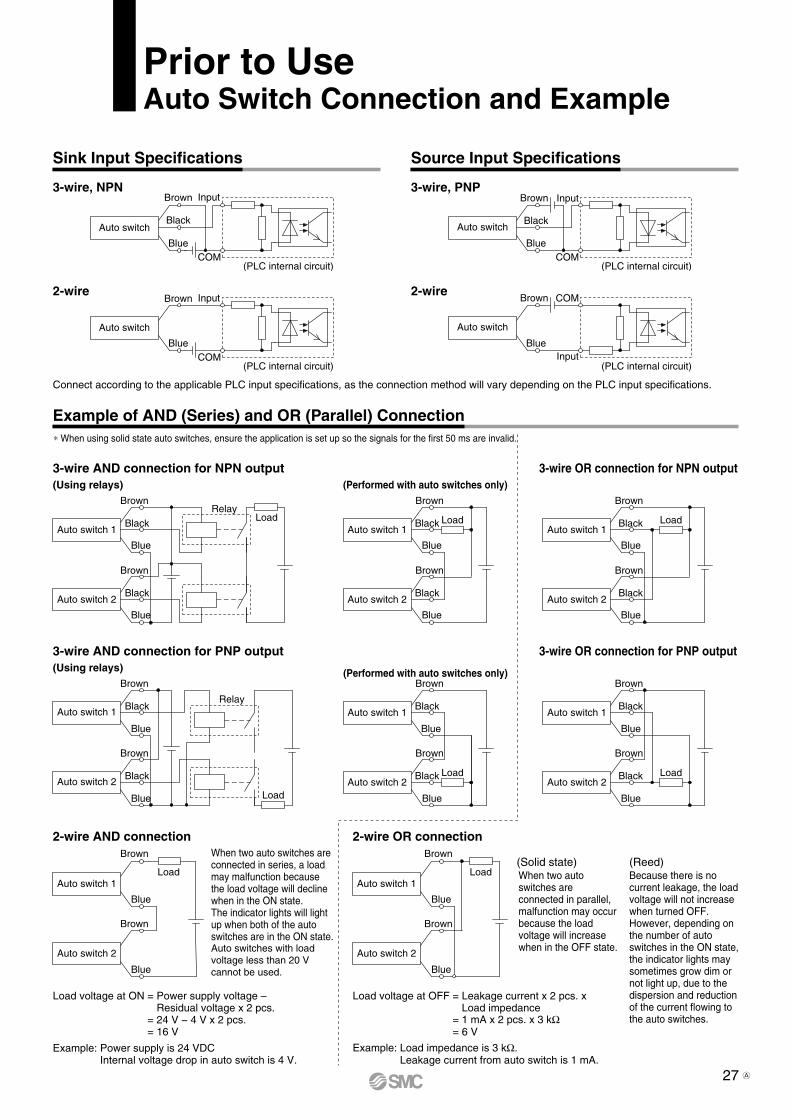
27
COM
Input
(PLC internal circuit)
Blue
Black
Brown
Auto switch
COM
Input
(PLC internal circuit)
Blue
Brown
Auto switch
COM
Input
(PLC internal circuit)
Blue
Black
Brown
Auto switch
Input
COM
(PLC internal circuit)
Blue
Brown
Auto switch
RelayLoad
Blue
Black
Brown
Auto switch 2
Blue
Black
Brown
Auto switch 1Load
Blue
Black
Brown
Auto switch 2
Blue
Black
Brown
Auto switch 1
Relay
LoadBlue
Black
Brown
Auto switch 2
Blue
Black
Brown
Auto switch 1
Load
Blue
Black
Brown
Auto switch 2
Blue
Black
Brown
Auto switch 1
Load
Blue
Brown
Auto switch 2
Blue
Brown
Auto switch 1
Load
Blue
Black
Brown
Auto switch 2
Blue
Black
Brown
Auto switch 1
Load
Blue
Black
Brown
Auto switch 2
Blue
Black
Brown
Auto switch 1
Load
Blue
Brown
Auto switch 2
Blue
Brown
Auto switch 1
Prior to UseAuto Switch Connection and Example
2-wire OR connection2-wire AND connection
3-wire OR connection for PNP output
(Performed with auto switches only)(Using relays)
3-wire AND connection for PNP output
3-wire OR connection for NPN output(Performed with auto switches only)(Using relays)
3-wire AND connection for NPN output
2-wire
3-wire, PNP
2-wire
3-wire, NPN
Load voltage at ON = Power supply voltage – Residual voltage x 2 pcs.
= 24 V − 4 V x 2 pcs.= 16 V
Example: Power supply is 24 VDC Internal voltage drop in auto switch is 4 V.
Load voltage at OFF = Leakage current x 2 pcs. x Load impedance
= 1 mA x 2 pcs. x 3 kW= 6 V
Example: Load impedance is 3 kW. Leakage current from auto switch is 1 mA.
(Solid state) (Reed)When two auto switches are connected in series, a load may malfunction because the load voltage will decline when in the ON state.The indicator lights will light up when both of the auto switches are in the ON state.Auto switches with load voltage less than 20 V cannot be used.
When two auto switches are connected in parallel, malfunction may occur because the load voltage will increase when in the OFF state.
Because there is no current leakage, the load voltage will not increase when turned OFF. However, depending on the number of auto switches in the ON state, the indicator lights may sometimes grow dim or not light up, due to the dispersion and reduction of the current flowing to the auto switches.
Connect according to the applicable PLC input specifications, as the connection method will vary depending on the PLC input specifications.
* When using solid state auto switches, ensure the application is set up so the signals for the first 50 ms are invalid.
Example of AND (Series) and OR (Parallel) Connection
Sink Input Specifications Source Input Specifications
A
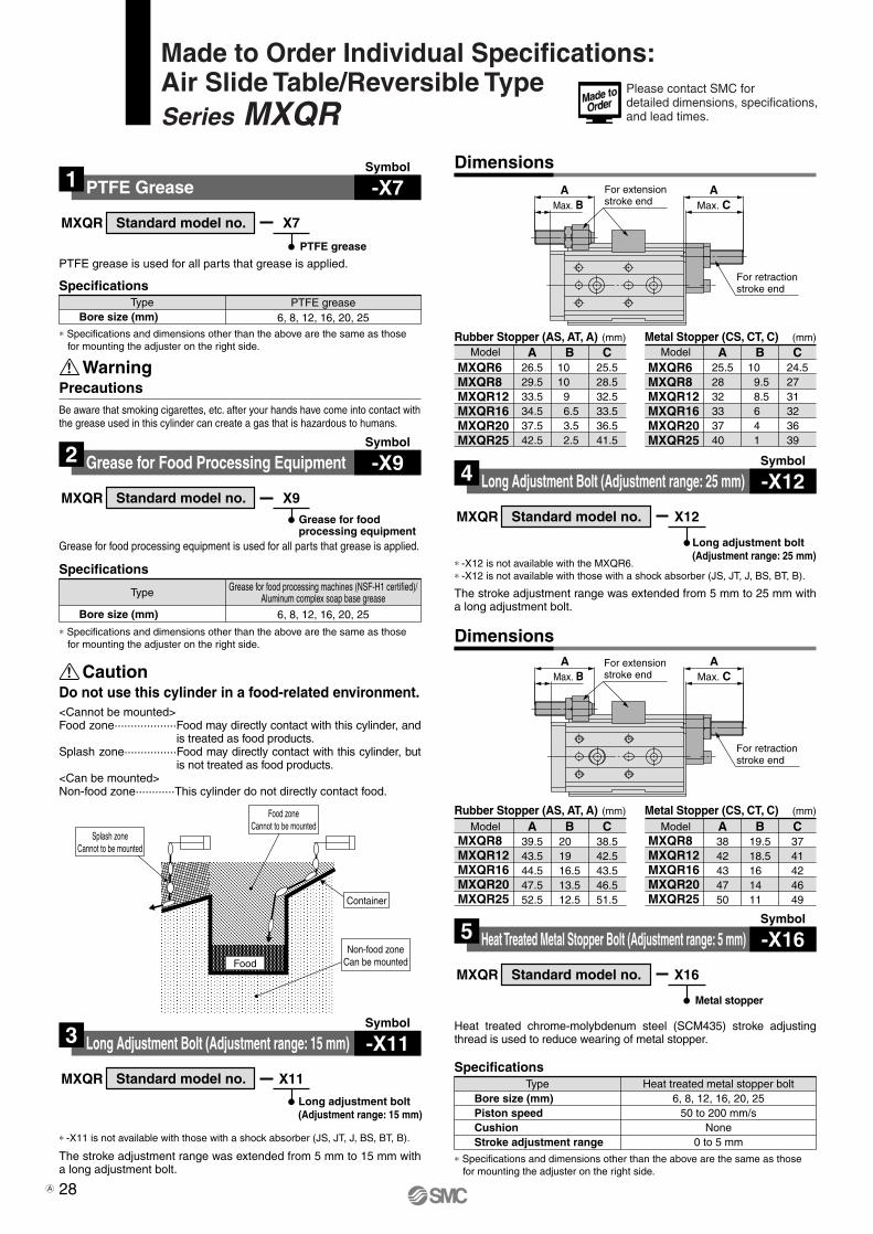
For retractionstroke end
For extensionstroke end Max. C
AAMax. B
For retractionstroke end
For extensionstroke end Max. C
AAMax. B
SpecificationsPTFE grease
6, 8, 12, 16, 20, 25Bore size (mm)
MXQR X7
PTFE grease is used for all parts that grease is applied.
PTFE grease
∗ Specifications and dimensions other than the above are the same as those for mounting the adjuster on the right side.
Standard model no.
Symbol
PTFE Grease1 -X7
SpecificationsGrease for food processing machines (NSF-H1 certified)/
Aluminum complex soap base grease
6, 8, 12, 16, 20, 25Bore size (mm)
MXQR X9
Grease for food processing equipment is used for all parts that grease is applied.
Grease for foodprocessing equipment
∗ Specifications and dimensions other than the above are the same as those for mounting the adjuster on the right side.
Standard model no.
Symbol
Grease for Food Processing Equipment2 -X9
∗ -X12 is not available with the MXQR6.∗ -X12 is not available with those with a shock absorber (JS, JT, J, BS, BT, B).
The stroke adjustment range was extended from 5 mm to 25 mm with a long adjustment bolt.
MXQR X12
Long adjustment bolt(Adjustment range: 25 mm)
Standard model no.
Symbol
Long Adjustment Bolt (Adjustment range: 25 mm)4 -X12
(mm)Rubber Stopper (AS, AT, A) (mm)Metal Stopper (CS, CT, C)
∗ -X11 is not available with those with a shock absorber (JS, JT, J, BS, BT, B).
The stroke adjustment range was extended from 5 mm to 15 mm with a long adjustment bolt.
MXQR X11
Long adjustment bolt(Adjustment range: 15 mm)
Standard model no.
Symbol
Long Adjustment Bolt (Adjustment range: 15 mm)3 -X11
(mm)Rubber Stopper (AS, AT, A) (mm)Metal Stopper (CS, CT, C)
SpecificationsHeat treated metal stopper bolt
6, 8, 12, 16, 20, 2550 to 200 mm/s
None0 to 5 mm
Bore size (mm)Piston speedCushionStroke adjustment range
MXQR X16
Metal stopper
∗ Specifications and dimensions other than the above are the same as those for mounting the adjuster on the right side.
Standard model no.
Symbol
Heat Treated Metal Stopper Bolt (Adjustment range: 5 mm)5 -X16
Heat treated chrome-molybdenum steel (SCM435) stroke adjusting thread is used to reduce wearing of metal stopper.
Dimensions
Dimensions
Type
Type
Type
Model A39.543.544.547.552.5
B20 19 16.513.512.5
C38.542.543.546.551.5
Model A3842434750
B19.518.516 14 11
C3741424649
Model A26.529.533.534.537.542.5
B10 10 9
6.5 3.5 2.5
C25.528.532.533.536.541.5
Model A25.528 32 33 37 40
B10 9.5 8.56 4 1
C24.527 31 32 36 39
MXQR8MXQR12MXQR16MXQR20MXQR25
MXQR8MXQR12MXQR16MXQR20MXQR25
MXQR6MXQR8MXQR12MXQR16MXQR20MXQR25
MXQR6MXQR8MXQR12MXQR16MXQR20MXQR25
PrecautionsWarning
Be aware that smoking cigarettes, etc. after your hands have come into contact with the grease used in this cylinder can create a gas that is hazardous to humans.
Caution
<Cannot be mounted>Food zone···················Food may directly contact with this cylinder, and
is treated as food products.Splash zone················Food may directly contact with this cylinder, but
is not treated as food products.<Can be mounted>Non-food zone············This cylinder do not directly contact food.
FoodNon-food zone
Can be mounted
Container
Splash zoneCannot to be mounted
Do not use this cylinder in a food-related environment.
Food zoneCannot to be mounted
28
Made to Order Individual Specifications:Air Slide Table/Reversible TypeSeries MXQR
Please contact SMC for detailed dimensions, specifications, and lead times.
A

For retraction stroke end
For extensionstroke end Max. C
AAMax. B
For retraction stroke end
For extensionstroke end Max. C
AAMax. B
SpecificationsWithout built-in auto switch magnet
6, 8, 12, 16, 20, 25Not mountable
Bore size (mm)Auto switch
MXQR X33
Without built-in auto switch magnet
∗ Specifications and dimensions other than the above are the same as those for mounting the adjuster on the right side.
Standard model no.
Symbol
Without Built-in Auto Switch Magnet 8 -X33
This product does not have a magnet for an auto switch.It is suitable for applications where magnetic force is not acceptable.Heat treated chrome-molybdenum steel (SCM435) stroke adjusting
thread is used to reduce wearing of metal stopper.The stroke adjustment range was extended from 5 mm to 15 mm with a long adjustment bolt.
MXQR X17
Metal stopper(Adjustment range: 15 mm)
Standard model no.
Symbol
Heat Treated Metal Stopper Bolt (Adjustment range: 15 mm)6 -X17
Model
MXQR6MXQR8MXQR12MXQR16MXQR20MXQR25
(mm)
A25.5
28
32
33
37
40
B10
9.5
8.5
6
4
1
C24.5
27
31
32
36
39
Heat treated chrome-molybdenum steel (SCM435) stroke adjusting thread is used to reduce wearing of metal stopper.The stroke adjustment range was extended from 5 mm to 25 mm with a long adjustment bolt.
MXQR X18
Metal stopper(Adjustment range: 25 mm)
Standard model no.
Model
MXQR8MXQR12MXQR16MXQR20MXQR25
(mm)
A38
42
43
47
50
B19.5
18.5
16
14
11
C37
41
42
46
49
Symbol
Heat Treated Metal Stopper Bolt (Adjustment range: 25 mm)7 -X18
∗ -X18 is not available with the MXQR6.
SpecificationsFluororubber seal6, 8, 12, 16, 20, 25
FluororubberBore size (mm)Seal material
MXQR X39
Fluororubber seal
∗ Specifications and dimensions other than the above are the same as those for mounting the adjuster on the right side.
Standard model no.
Symbol
Fluororubber Seal9 -X39
Change the materials for the piston seal, rod seal, O-rings and scrapers (rubber lined parts) to fluororubber.
SpecificationsAnti-corrosive guide unit
6, 8, 12, 16, 20, 25Special anti-corrosive treatment ∗2
Bore size (mm)Surface treatment
MXQR X42
Anti-corrosive guide unit
∗1 Specifications and dimensions other than the above are the same as those for mounting the adjuster on the right side.
∗2 Special anti-corrosive treatment makes the table and the guide block black.
Standard model no.
Symbol
Anti-corrosive Guide Unit10 -X42
Martensitic stainless steel is used for table and guide block. Use this treatment if more effective anti-corrosiveness is necessary.Table and guide block are given anti-corrosive treatment.
SpecificationsEPDM seal
6, 8, 12, 16, 20, 25EPDM
PTFE grease
Bore size (mm)Seal materialGrease
MXQR X45
EPDM seal
∗ Specifications and dimensions other than the above are the same as those for mounting the adjuster on the right side.
Standard model no.
Symbol
EPDM Seal11 -X45
Change the materials for the piston seal, rod seal, O-rings and scrapers (rubber lined parts) to EPDM.
Dimensions
Dimensions
Type
Type
Type
Type
PrecautionsWarning
Be aware that smoking cigarettes, etc. after your hands have come into contact with the grease used in this cylinder can create a gas that is hazardous to humans.
29
Made to Order Individual Specifications:Air Slide Table/Reversible TypeSeries MXQR
Please contact SMC for detailed dimensions, specifications, and lead times.
A

1. The compatibility of the product is the responsibility of the person who designs the equipment or decides its specifications.Since the product specified here is used under various operating conditions, its compatibility with specific equipment must be decided by the person who designs the equipment or decides its specifications based on necessary analysis and test results. The expected performance and safety assurance of the equipment will be the responsibility of the person who has determined its compatibility with the product. This person should also continuously review all specifications of the product referring to its latest catalog information, with a view to giving due consideration to any possibility of equipment failure when configuring the equipment.
2. Only personnel with appropriate training should operate machinery and equipment.The product specified here may become unsafe if handled incorrectly. The assembly, operation and maintenance of machines or equipment including our products must be performed by an operator who is appropriately trained and experienced.
3. Do not service or attempt to remove product and machinery/equipment until safety is confirmed.1. The inspection and maintenance of machinery/equipment should only
be performed after measures to prevent falling or runaway of the driven objects have been confirmed.
2. When the product is to be removed, confirm that the safety measures as mentioned above are implemented and the power from any appropriate source is cut, and read and understand the specific product precautions of all relevant products carefully.
3. Before machinery/equipment is restarted, take measures to prevent unexpected operation and malfunction.
4. Contact SMC beforehand and take special consideration of safety measures if the product is to be used in any of the following conditions. 1. Conditions and environments outside of the given specifications, or use
outdoors or in a place exposed to direct sunlight.2. Installation on equipment in conjunction with atomic energy, railways,
air navigation, space, shipping, vehicles, military, medical treatment, combustion and recreation, or equipment in contact with food and beverages, emergency stop circuits, clutch and brake circuits in press applications, safety equipment or other applications unsuitable for the standard specifications described in the product catalog.
3. An application which could have negative effects on people, property, or animals requiring special safety analysis.
4. Use in an interlock circuit, which requires the provision of double interlock for possible failure by using a mechanical protective function, and periodical checks to confirm proper operation.
Warning
Limited warranty and Disclaimer/Compliance Requirements The product used is subject to the following “Limited warranty and Disclaimer” and “Compliance Requirements”.Read and accept them before using the product.
1. The product is provided for use in manufacturing industries.The product herein described is basically provided for peaceful use in manufacturing industries. If considering using the product in other industries, consult SMC beforehand and exchange specifications or a contract if necessary. If anything is unclear, contact your nearest sales branch.
Caution
Limited warranty and Disclaimer1. The warranty period of the product is 1 year in service or 1.5
years after the product is delivered.∗2)
Also, the product may have specified durability, running distance or replacement parts. Please consult your nearest sales branch.
2. For any failure or damage reported within the warranty period which is clearly our responsibility, a replacement product or necessary parts will be provided. This limited warranty applies only to our product independently, and not to any other damage incurred due to the failure of the product.
3. Prior to using SMC products, please read and understand the warranty terms and disclaimers noted in the specified catalog for the particular products.
∗2) Vacuum pads are excluded from this 1 year warranty.A vacuum pad is a consumable part, so it is warranted for a year after it is delivered. Also, even within the warranty period, the wear of a product due to the use of the vacuum pad or failure due to the deterioration of rubber material are not covered by the limited warranty.
Compliance Requirements1. The use of SMC products with production equipment for the manufac-
ture of weapons of mass destruction (WMD) or any other weapon is strictly prohibited.
2. The exports of SMC products or technology from one country to another are governed by the relevant security laws and regulations of the countries involved in the transaction. Prior to the shipment of a SMC product to another country, assure that all local rules governing that export are known and followed.
These safety instructions are intended to prevent hazardous situations and/or equipment damage. These instructions indicate the level of potential hazard with the labels of “Caution,” “Warning” or “Danger.” They are all important notes for safety and must be followed in addition to International Standards (ISO/IEC)∗1), and other safety regulations.
∗1) ISO 4414: Pneumatic fluid power – General rules relating to systems.ISO 4413: Hydraulic fluid power – General rules relating to systems.IEC 60204-1: Safety of machinery – Electrical equipment of machines.
(Part 1: General requirements)ISO 10218-1: Manipulating industrial robots - Safety.etc.
Caution indicates a hazard with a low level of risk which, if not avoided, could result in minor or moderate injury.
Warning indicates a hazard with a medium level of risk which, if not avoided, could result in death or serious injury.
Caution:
Warning:
Danger :Danger indicates a hazard with a high level of risk which, if not avoided, will result in death or serious injury.
Safety Instructions
Safety Instructions Be sure to read “Handling Precautions for SMC Products” (M-E03-3) before using.