air shower measurements with lofar - stanford university · proceedings of the 31st icrc, Ł od´ z...
TRANSCRIPT
PROCEEDINGS OF THE 31st ICRC, ŁODZ 2009 1
Air Shower Measurements with LOFAR
A. Horneffer ∗, L. Bahren∗, S. Buitink∗, A. Corstanje∗, H. Falcke∗†, J.R. Horandel∗, S. Lafebre∗,O. Scholten‡, K. Singh‡, S. Thoudam∗, S. ter Veen∗
∗Department of Astrophysics/IMAPP, Radboud University Nijmegen, 6500 GL Nijmegen, The Netherlands†ASTRON, 7990 AA Dwingeloo, The Netherlands
‡Kernfysisch Versneller Instituut, NL-9747 AA Groningen, The Netherlands
Abstract. Understanding the radio emission fromair showers requires high precision measurements ofthe radio pulse front. LOFAR is a new radio telescopethat is being built in the Netherlands. The core ofLOFAR will have a higher density of radio antennasand better calibration than a dedicated air showerarray. This makes LOFAR a unique tool to study theradio properties of single air showers and thus testand refine our theoretical understanding of the radioemission process.
Triggering on the radio emission from air showersmeans detecting a nano-second radio pulse anddiscriminating real events from radio interference.At LOFAR, we will search for pulses in the digitaldata stream and use pulse-form parameters to dis-criminate real events from background. We will alsohave a small scintillator array to test and confirmthe performance of the radio only trigger and toprovide additional measurements for the air showerreconstruction and analysis.
Keywords: LOFAR, Radio
I. I NTRODUCTION
It has been known since 1965 that cosmic ray airshowers emit short radio pulses[1]. LOPES, aLOFARPrototype Station, was the first experiment that hasproven that with fast ADCs and modern computer tech-nology it is possible to measure these radio pulses evenin the presence of relatively strong RFI1 [2].
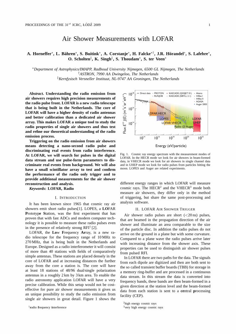
LOFAR, the Low FrequencyAr ray, is a new ra-dio telescope for the frequency range of 10 MHz to270 MHz, that is being built in the Netherlands andEurope. Designed as a radio interferometer it will consistof more than 40 stations with fields of comparativelysimple antennas. These stations are placed densely in thecore of LOFAR and at increasing distances the furtheraway from the core a station is. The core will haveat least 18 stations of 48/96 dual/single polarizationantennas in a roughly 2 km by 3 km area. To enable theradio astronomy application LOFAR will have a veryprecise calibration. While this setup would not be cost-effective for pure air shower measurements it gives usan unique possibility to study the radio emission fromsingle air showers in great detail. Figure 1 shows the
1radio frequencyinterference
Fig. 1. Cosmic ray energy spectrum with the measurement modes ofLOFAR. In the HECR mode we look for air showers in beam-formeddata, in VHECR mode we look for air showers in single channel dataand in UHEP mode we look for radio pulses from particles hitting themoon. LOPES and Auger are related experiments.
different energy ranges in which LOFAR will measurecosmic rays. The HECR2 and the VHECR3 mode bothmeasure air showers, they differ only in the methodof triggering, but share the same post-processing andanalysis software.
II. LOFAR A IR SHOWER TRIGGER
Air shower radio pulses are short (<20 ns) pulses,that are beamed in the propagation direction of the airshower and illuminate an area comparable to the sizeof the particle disc. In addition the radio pulses do notarrive on the ground in a plane but with some curvature.Compared to a plane wave the radio pulses arrive laterwith increasing distance from the shower axis. Theseproperties can be used to distinguish air shower pulsesfrom pulsed RFI.
In LOFAR there are two paths for the data. The signalsfrom each dipole are digitized and then are both sent tothe so called transient buffer boards (TBB) for storage ina memory ring-buffer and are processed in a continuousdata stream. In this stream the data is converted intofrequency bands, these bands are then beam-formed in agiven direction at the station level and the beam-formeddata from each station is sent to acentral processingfacility (CEP).
2high energy cosmic rays3very high energy cosmic rays
2 A. HORNEFFERet al. AIR SHOWERS WITH LOFAR
In the HECR mode we look at the beam-formed datafrom single stations. At CEP the beam-formed data isconverted back into time-domain for full time resolutionand searched for air shower candidate pulses. When asuitable candidate is found the data from the correspond-ing TBBs is saved to a file for off-line processing. As thebeam-forming reduces the solid angle but increases thesensitivity, this mode is useful for low energy showers.
At higher energies, in the VHECR mode, we look forpulses in the data streams of single channels. This isdone in three levels: the first level runs on the hardwareof the TBBs. There the data from each channel isfirst filtered with up to three so called infinite impulseresponse (IIR) filters, that can be configured as high-pass, low-pass, or notch filters. The filtered data is thensearched for pulses by evaluating the following equation:
|xi| > µi + aσi (1)
(With xi the input data,µi andσi the mean and standarddeviation of|xi| , anda a parameter.) As the input datais Gaussian distributedµi is proportional toσi, so thisequation can be simplified to:
|xi| > bµi (2)
which greatly eases implementation on the TBBs. Forevery xi above threshold a counter is increased by4 and decreased by one otherwise, unless it is zero.So by testing if this counter is above a given valueone can detect pulses in which several values closeto each other are above threshold. If such a pulse isdetected the pulse parametersposition in time, height,width, sum, average beforeandaverage after the pulseare calculated and sent in a message to the computercontrolling the station. On this computer the secondtrigger level runs. In this an incoming message is firstchecked if the pulse parameters disqualify a pulse foran air shower candidate. With the remaining pulses asimple coincidence check is done to detect air showercandidates. If the available computing power permits wethen can do a direction fit or look at the pulse heightpattern on the ground to identify RFI pulses. If a good airshower candidate is identified all TBBs of the station arenotified and their data are written to disk. Informationabout weak and good candidates is sent to CEP, whichthen can decide if a coincidence of weak pulses inseveral stations indicates an air shower in between them,or if a strong air shower warrants saving the data fromadditional stations.
III. T EST MEASUREMENTS
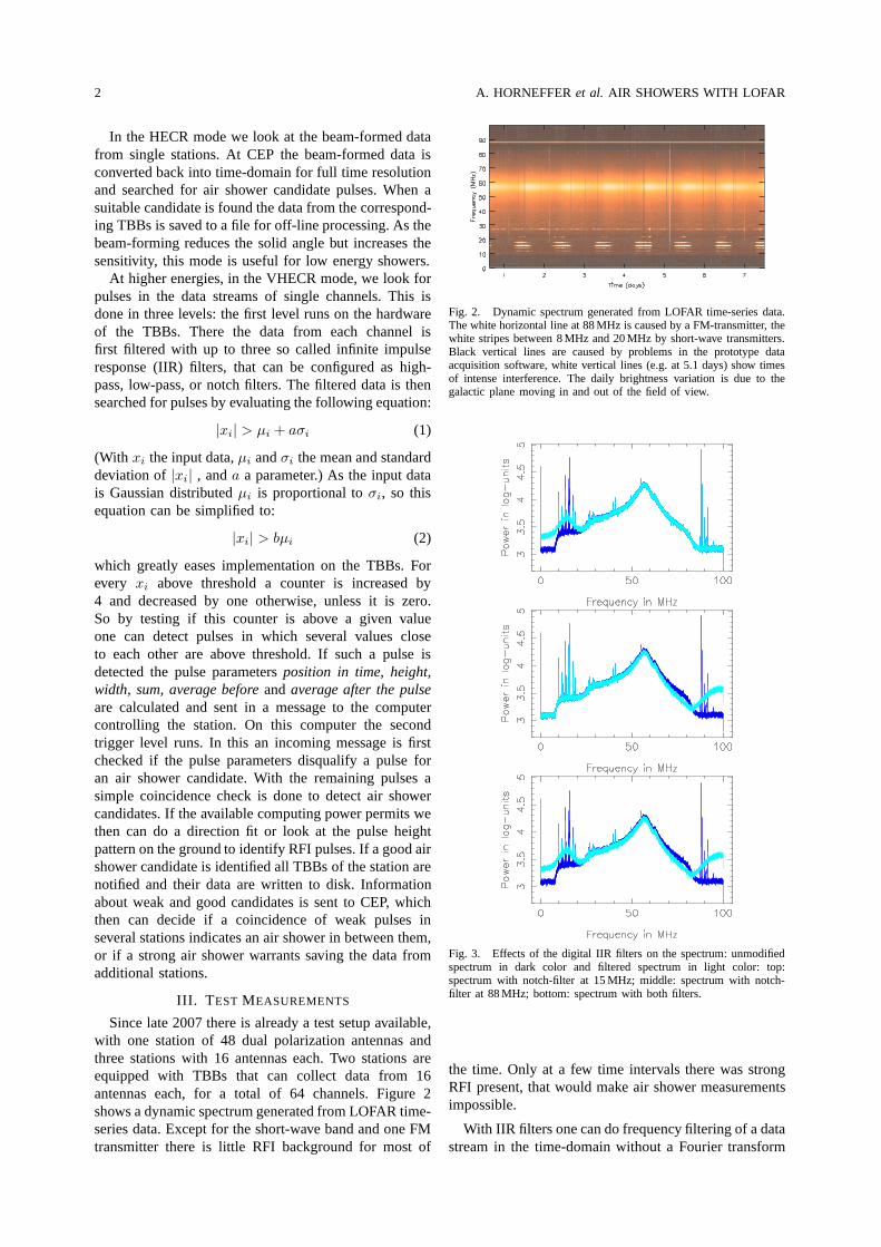
Since late 2007 there is already a test setup available,with one station of 48 dual polarization antennas andthree stations with 16 antennas each. Two stations areequipped with TBBs that can collect data from 16antennas each, for a total of 64 channels. Figure 2shows a dynamic spectrum generated from LOFAR time-series data. Except for the short-wave band and one FMtransmitter there is little RFI background for most of
Fig. 2. Dynamic spectrum generated from LOFAR time-series data.The white horizontal line at 88 MHz is caused by a FM-transmitter, thewhite stripes between 8 MHz and 20 MHz by short-wave transmitters.Black vertical lines are caused by problems in the prototypedataacquisition software, white vertical lines (e.g. at 5.1 days) show timesof intense interference. The daily brightness variation isdue to thegalactic plane moving in and out of the field of view.
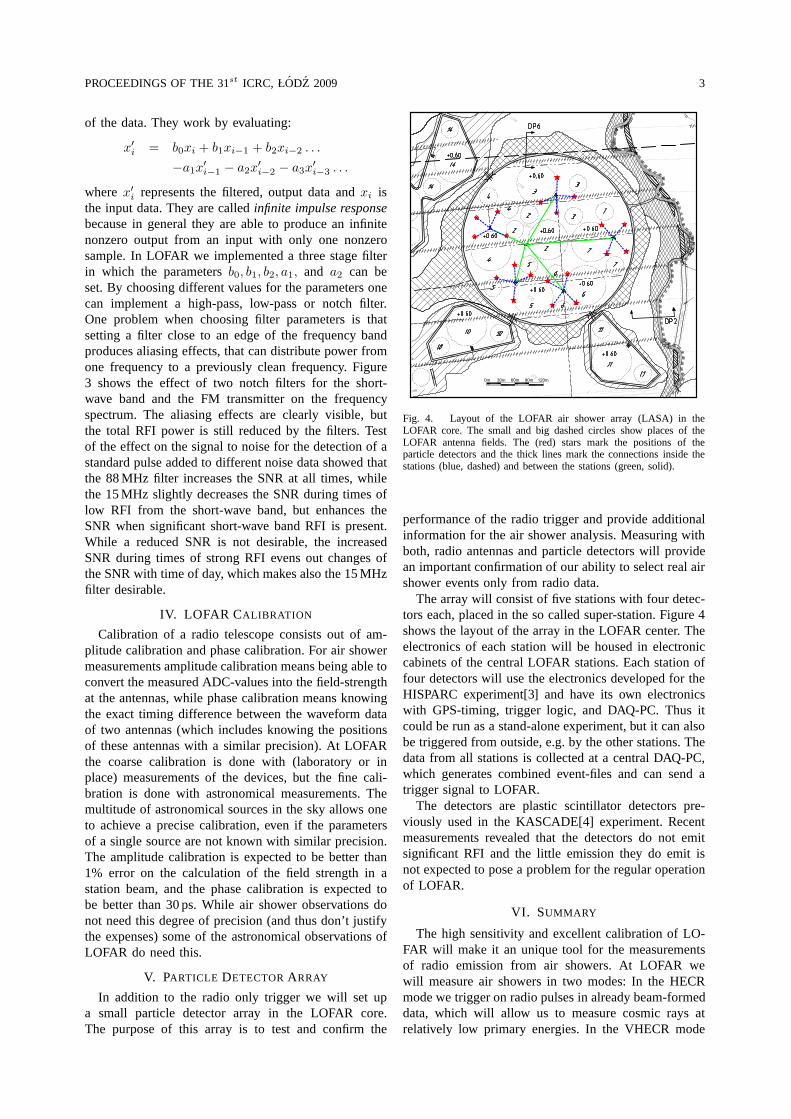
Fig. 3. Effects of the digital IIR filters on the spectrum: unmodifiedspectrum in dark color and filtered spectrum in light color: top:spectrum with notch-filter at 15 MHz; middle: spectrum with notch-filter at 88 MHz; bottom: spectrum with both filters.
the time. Only at a few time intervals there was strongRFI present, that would make air shower measurementsimpossible.
With IIR filters one can do frequency filtering of a datastream in the time-domain without a Fourier transform
PROCEEDINGS OF THE 31st ICRC, ŁODZ 2009 3
of the data. They work by evaluating:
x′
i= b0xi + b1xi−1 + b2xi−2 . . .
−a1x′
i−1− a2x
′
i−2− a3x
′
i−3. . .
wherex′
irepresents the filtered, output data andxi is
the input data. They are calledinfinite impulse responsebecause in general they are able to produce an infinitenonzero output from an input with only one nonzerosample. In LOFAR we implemented a three stage filterin which the parametersb0, b1, b2, a1, and a2 can beset. By choosing different values for the parameters onecan implement a high-pass, low-pass or notch filter.One problem when choosing filter parameters is thatsetting a filter close to an edge of the frequency bandproduces aliasing effects, that can distribute power fromone frequency to a previously clean frequency. Figure3 shows the effect of two notch filters for the short-wave band and the FM transmitter on the frequencyspectrum. The aliasing effects are clearly visible, butthe total RFI power is still reduced by the filters. Testof the effect on the signal to noise for the detection of astandard pulse added to different noise data showed thatthe 88 MHz filter increases the SNR at all times, whilethe 15 MHz slightly decreases the SNR during times oflow RFI from the short-wave band, but enhances theSNR when significant short-wave band RFI is present.While a reduced SNR is not desirable, the increasedSNR during times of strong RFI evens out changes ofthe SNR with time of day, which makes also the 15 MHzfilter desirable.
IV. LOFAR CALIBRATION
Calibration of a radio telescope consists out of am-plitude calibration and phase calibration. For air showermeasurements amplitude calibration means being able toconvert the measured ADC-values into the field-strengthat the antennas, while phase calibration means knowingthe exact timing difference between the waveform dataof two antennas (which includes knowing the positionsof these antennas with a similar precision). At LOFARthe coarse calibration is done with (laboratory or inplace) measurements of the devices, but the fine cali-bration is done with astronomical measurements. Themultitude of astronomical sources in the sky allows oneto achieve a precise calibration, even if the parametersof a single source are not known with similar precision.The amplitude calibration is expected to be better than1% error on the calculation of the field strength in astation beam, and the phase calibration is expected tobe better than 30 ps. While air shower observations donot need this degree of precision (and thus don’t justifythe expenses) some of the astronomical observations ofLOFAR do need this.
V. PARTICLE DETECTORARRAY
In addition to the radio only trigger we will set upa small particle detector array in the LOFAR core.The purpose of this array is to test and confirm the
0m 30m 60m 90m 120m
Fig. 4. Layout of the LOFAR air shower array (LASA) in theLOFAR core. The small and big dashed circles show places of theLOFAR antenna fields. The (red) stars mark the positions of theparticle detectors and the thick lines mark the connectionsinside thestations (blue, dashed) and between the stations (green, solid).
performance of the radio trigger and provide additionalinformation for the air shower analysis. Measuring withboth, radio antennas and particle detectors will providean important confirmation of our ability to select real airshower events only from radio data.
The array will consist of five stations with four detec-tors each, placed in the so called super-station. Figure 4shows the layout of the array in the LOFAR center. Theelectronics of each station will be housed in electroniccabinets of the central LOFAR stations. Each station offour detectors will use the electronics developed for theHISPARC experiment[3] and have its own electronicswith GPS-timing, trigger logic, and DAQ-PC. Thus itcould be run as a stand-alone experiment, but it can alsobe triggered from outside, e.g. by the other stations. Thedata from all stations is collected at a central DAQ-PC,which generates combined event-files and can send atrigger signal to LOFAR.
The detectors are plastic scintillator detectors pre-viously used in the KASCADE[4] experiment. Recentmeasurements revealed that the detectors do not emitsignificant RFI and the little emission they do emit isnot expected to pose a problem for the regular operationof LOFAR.
VI. SUMMARY
The high sensitivity and excellent calibration of LO-FAR will make it an unique tool for the measurementsof radio emission from air showers. At LOFAR wewill measure air showers in two modes: In the HECRmode we trigger on radio pulses in already beam-formeddata, which will allow us to measure cosmic rays atrelatively low primary energies. In the VHECR mode

4 A. HORNEFFERet al. AIR SHOWERS WITH LOFAR
we trigger on pulses in single channel data. This triggeralgorithm will have three steps: on the hardware thatwrites the raw ADC data into a memory buffer, on thePC controlling a LOFAR station, and on the centralprocessing facility. The algorithms for the first step and apreliminary version of the second step have already beenimplemented and the first tests have been successful. Wealso plan to set up a small particle detector array whichwill allow us to confirm that we can pick out real airshower events only with our radio trigger.
REFERENCES
[1] J. V. Jelley et al., Nature205 (1965) 327[2] H. Falcke et al., LOPES collaboration, Nature435 (2005) 313[3] High School Project on Astro-Physics Research with Cosmics,
http://www.hisparc.nl/[4] T. Antoni et al., KASCADE collaboration, NIMA513 (2003)
490