air plus 5 manual · 1.4 sql server 2008 express installation air plus uses sql server 2008 express...
TRANSCRIPT

Met One Instruments, Inc Corporate Sales & Service: 1600 NW Washington Blvd. Grants Pass, OR 97526
Tel (541) 471-7111 Fax (541) 471-7116 www.metone.com - [email protected]
OPERATORS MANUAL
AIR PLUS 5


AIR PLUS-9800 Rev J 1
Copyright Notice Operators Manual Air Plus 5 © Copyright 2019 Met One Instruments, Inc. All Rights Reserved Worldwide. No part of this publication may be reproduced, transmitted, transcribed, stored in a retrieval system, or translated into any other language in any form by any means without the express written permission of Met One Instruments, Inc.
Technical Support
Should you require support, please consult your printed documentation or our website www.metone.com to resolve your problem. If you are still experiencing difficulty, you may contact a Technical Service representative during normal business hours;
Monday – Friday 7:00 a.m. to 4:00 p.m. Pacific Time.
Voice: (541) 471-7111
Fax: (541) 471-7116
E-Mail: [email protected]
Mail: Technical Services Department Met One Instruments, Inc. 1600 NW Washington Blvd Grants Pass, OR 97526

AIR PLUS-9800 Rev J 2
Table of Contents
Overview ........................................................................................................................ 4
1 Installation ............................................................................................................. 5
1.1 Getting Started ................................................................................................ 5
1.2 Installation Options .......................................................................................... 5
1.3 .NET 4 Framework Installation ........................................................................ 6
1.4 SQL Server 2008 Express Installation ............................................................ 6
1.5 Windows Installer 4.5 ...................................................................................... 7
1.6 Windows Imaging Component (Windows XP Only) ........................................ 8
1.7 Air Plus installation .......................................................................................... 9
2 Air Plus ................................................................................................................... 9
2.1 Configuring Air Plus 5 for Multiple Windows Users ....................................... 10 2.1.1 Granting SQL Access Using a Known Domain Login ....................................................... 10 2.1.2 Granting SQL Access Using a List of Domain Users ........................................................ 12 2.1.3 Revoking SQL Database Access ...................................................................................... 13
3 Configuration ....................................................................................................... 14
3.1 Defining a New Station .................................................................................. 14 3.1.1 Connect Tab ...................................................................................................................... 16 3.1.2 Logger Tab ........................................................................................................................ 17 3.1.3 Channel Tab ...................................................................................................................... 18 3.1.4 Queue Tab and the Auto Export Feature .......................................................................... 19 3.1.5 Notification Tab ................................................................................................................. 20
4 Notifications ........................................................................................................ 20
4.1 Notification Event Types ............................................................................... 20 4.1.1 New Data Download ......................................................................................................... 20 4.1.2 Data Retrieval Failed......................................................................................................... 21 4.1.3 Data Conditional ................................................................................................................ 21
4.2 Notification Send Types ................................................................................ 22 4.2.1 E-mail ................................................................................................................................ 22 4.2.2 Text Message .................................................................................................................... 22 4.2.3 Twitter ............................................................................................................................... 23
5 Data Retrieval ...................................................................................................... 27
5.1 Manual Data Retrieval ................................................................................... 27
5.2 Automatic Data Retrieval Using the Queue Feature ..................................... 29
5.3 Real Time Monitor ......................................................................................... 29
6 Viewing Data ........................................................................................................ 30

AIR PLUS-9800 Rev J 3
6.1 Single Channel Data in Table Format ........................................................... 30 6.1.1 Daily Average Tab............................................................................................................. 31 6.1.2 Hourly Average Tab .......................................................................................................... 32 6.1.3 Data Logger (or Custom) Average Tab............................................................................. 33 6.1.4 Selecting a Date Range .................................................................................................... 34 6.1.5 Outliers .............................................................................................................................. 35
6.2 Single Channel Trend Reports ...................................................................... 36
6.3 Multi-Channel Data ....................................................................................... 37
7 Updates ................................................................................................................ 39
8 Printed Reports ................................................................................................... 39
8.1 Creating Reports ........................................................................................... 40
8.2 Saving Report Templates .............................................................................. 41
9 Wind Rose Reports ............................................................................................. 41
9.1 Creating Reports ........................................................................................... 41
10 Exporting and Importing Data ............................................................................ 43
10.1 Exporting data ............................................................................................... 43
10.2 Auto Export ................................................................................................... 44 10.2.1 Manual Execution .............................................................................................................. 44 10.2.2 File Options ....................................................................................................................... 45 10.2.3 CSV Data Options ............................................................................................................. 47 10.2.4 Interaction of Formatting Options ...................................................................................... 48
10.3 Importing data ............................................................................................... 49
Appendix A 466A Channel Parameters ................................................................ 50
Appendix B BAM-1020 Channel Parameters ....................................................... 51
Appendix C E-BAM Channel Parameters ............................................................. 52
Appendix D E-Sampler Channel Parameters ....................................................... 53
Appendix E Status Column Alarm Codes by Device .......................................... 54

AIR PLUS-9800 Rev J 4
Overview
Air Plus software includes all of the functions required for the collection, viewing of data, and production of both tabular and graphic reports needed by most users of an air quality or other environmental monitoring system. It is designed for use with the Met One Instruments, Inc. line of data collection products.
The software provides a complete data collection package for each of the various products and easy archiving of data. It also includes printed reports, real-time operation and automatic daily calculations.
Data collection can be performed automatically based on the requirements of the system. It can be done at a specified averaging interval or on a daily basis. Data can be collected via direct connection, direct radio link, standard telephone modem connection, cellular telephone modem, or by an easy to carry data transfer module.
Archived data can be reviewed in standard tabular format, or as typical line charts displaying either a single parameter or multiple parameters. The graphics package also includes the capability to produce wind rose charts. There is an export function that allows the user to export data in standard comma separated (*.csv) format and an import feature that will allow users to import existing data in to a new station.
Follow the onscreen installation instructions and you will be ready to collect data in just a few minutes. Systems manufactured and assembled by Met One Instruments, Inc. will include a station disk or data file that is used to automatically configure the Air Plus software. Other configurations may require the operator to enter the necessary setup values for their specific application. Recommended System Requirements: Processor Speed: 1GHz or faster Memory: 512MB minimum Disk Space: 60MB Operating System: Windows XP, Windows Vista, Windows 7, Windows 8

AIR PLUS-9800 Rev J 5
1 Installation
The necessary installation files are supplied on a standard CD-ROM.
1.1 Getting Started
Insert the CD-ROM into your computer and the Auto-run program will automatically begin the software installation process. If the installation program does not automatically launch when inserting the CD-ROM, you may manually begin the installation process. Press the Windows START button and select “Run…” Press the “Browse…” button and select your CD-ROM drive. Open the “Software” folder, select the file labeled “setup.exe” and press the “Open” button. Press the “OK” button to begin the installation process.
1.2 Installation Options
ATTENTION: The Air Plus installation CD includes the USB drivers necessary to communicate with all Met One Instruments, Inc. particle counters via the USB port of your computer. These drivers must be installed before connecting one of them to the USB port on your computer. If the supplied drivers are not installed first, Windows may install generic drivers that are not compatible with the counters. These drivers are also included with all Met One Instruments, Inc. particle counters able to communicate via USB. If you already have them installed on your computer, you do not need to install them again now. To install the USB drivers, click on the “USB Drivers” menu selection on the splash screen. These drivers may be installed either before or after the installation of Particle View.

AIR PLUS-9800 Rev J 6
1.3 .NET 4 Framework Installation Air Plus uses the .NET 4 framework. The installation process will detect if you meet the requirements. If your computer does not meet these requirements, you will be prompted to install the necessary files for Air Plus to run properly.
It will take a few minutes for .NET Framework 4 to install. Once completed, the setup may ask you to reboot your computer. Once rebooted, the installation of Air Plus will continue. 1.4 SQL Server 2008 Express Installation Air Plus uses SQL Server 2008 Express to store all data from the particle counters. The installation process will search your computer to verify you have it loaded. If not, the installer will install it before installing Air Plus.

AIR PLUS-9800 Rev J 7
It will take a few minutes for SQL Server 2008 Express to install. Once completed, the setup may ask you to reboot your computer. Once rebooted, the installation of Air Plus will continue. 1.5 Windows Installer 4.5 Air Plus uses the newest version of windows installer, 4.5, for setting up Air Plus properly. The installation process will detect if you meet the requirements. If your computer does not meet these requirements, you will be prompted to install Windows Installer 4.5.

AIR PLUS-9800 Rev J 8
It will take a few minutes for .NET Framework 4 to install. Once completed, the setup may ask you to reboot your computer. Once rebooted, the installation of Air Plus will continue. 1.6 Windows Imaging Component (Windows XP Only) On Windows XP machines, in order to properly install the .NET 4 Framework, Windows Imaging Component may be needed. The installation process will detect if you meet the requirements. If your computer does not meet these requirements, you will be prompted to install Windows Imaging Component.

AIR PLUS-9800 Rev J 9
It will take a few minutes for Windows Imaging Component to install. Once completed, the setup may ask you to reboot your computer. Once rebooted, the installation of Air Plus will continue. 1.7 Air Plus installation
Follow the on screen prompts to finish installing Air Plus. After the installation has finished, the installation wizard will confirm the process was successful.
IMPORTANT: Once installation is complete, it is important to run Windows Update and download all critical updates.
2 Air Plus To open Air Plus, open the start menu and navigate to the Met One directory. Under the Met One directory there will be an Air Plus folder, click on the AirPlus5 icon to start Air Plus for the first time.

AIR PLUS-9800 Rev J 10
2.1 Configuring Air Plus 5 for Multiple Windows Users
If you are installing and using Air Plus 5 only on a single Windows User Login, the installation is now complete. Please proceed to Section 2.
However, if one or more Windows users in addition to the user that has installed Air Plus 5 will be using the software, each Windows Login ID will need to be granted access to the SQL Server database individually. SQL database access privileges are initially granted and removed using the Windows Login ID that installed Air Plus 5. Once additional ID’s are added, they are also able to manage SQL database access privileges.
To configure Windows user SQL database access, open Air Plus 5 and click on the button located in the lower right of the main screen. This will open the Set up SQL User window. On the left hand side you will be able to see and add Windows domains and users. On the right hand side, you will be able to see and remove Windows users that have been given access to the SQL database.
2.1.1 Granting SQL Access Using a Known Domain Login

AIR PLUS-9800 Rev J 11
To add specific users, in the Option 1 section select the domain that the Windows login will use and then enter the login name in the space to the right. The login name must be entered exactly as it appears in the domain list.
Press the button and Air Plus 5 will locate that user ID and add it to the access list on the far right. If the name does not match exactly what is in the domain list, Air Plus 5 will not find it and it will not be added.
The user name must exist in order to add it to the list. You cannot add a Windows user in Air Plus 5 if it has not already been added to the domain.

AIR PLUS-9800 Rev J 12
2.1.2 Granting SQL Access Using a List of Domain Users
To see all domain users, press the button. You will see all domains to which the computer belongs and all domain users. If you have a large network, this list may take a few minutes to populate.
Using the checkboxes, select all users that will be using Air Plus 5 and press the button. Air Plus 5 will add all of them to the access list on the far right.

AIR PLUS-9800 Rev J 13
2.1.3 Revoking SQL Database Access
Sometimes a Windows user will need to be removed from the SQL database access list.
If the “Other Users” list on the far right is not populated, just press the button located beneath it. Using the checkboxes, select all users that need to be removed and then press the
button. Air Plus 5 will delete them from the access list.

AIR PLUS-9800 Rev J 14
3 Configuration
If the Air Plus software has been supplied as part of a system, a setup disk or data file will be supplied on a separate CD-ROM disc. The setup disk contains all of the information and files necessary to automatically configure the program to communicate with the system as it is shipped from the factory.
If the software has been purchased without a system, and a setup disk was not provided, then the configuration details will need to be manually input. See section 3.1 to define a new station and then skip to section 3.3 for manual configuration directions.
3.1 Defining a New Station
Whether using a setup disk or manually configuring your station, you must first define the station
to be used. From the main screen (shown below), press the button to enter the Station Definition screen.

AIR PLUS-9800 Rev J 15
Air Plus gives users the option to manually configure a station or have Air Plus find the product and automatically create the station. If your product is being stored on the cloud, choose the GS Cloud option to download the data from the cloud.
By choosing the automatic method, you must supply a station name and connection information. Air Plus will then attempt to connect to the device and automatically configure the station based on the device discovered.

AIR PLUS-9800 Rev J 16
The Station Definition screen has several tabs for configuring different parameters of your station. Users can manually fill out all the station information or if automatic configuration was selected, all the required information will be filled out for the user.
3.1.1 Connect Tab
This tab allows the entry of a station name and description, setting the logger type, and defining the method of connection to the logger.
If you are using a USB to serial adapter, you will need to verify which COM Port your computer has assigned to it. You can find this by going to Start Menu / Control Panel / System / Hardware / Device Manager / Ports. You should see your adapter listed here with a COM4 or similar in parenthesis after it. This is the port number to select in the drop down box on the Station Definition screen. If you do not see your adapter listed, your computer does not recognize it and has not installed it for use. Most likely, you will need to load the drivers that should have come with it.
If you are dialing out to a modem connected to the device out in the field, you need to select the COM Port that your computer modem uses and check the Dial Up box. Add the phone number exactly as it will be dialed (include a 1 if it is long distance). Do not use any dashes or spaces.
If you have your device connected to a network using an IP Address or a modem that is using an IP Address instead of a traditional dial in phone number, you will need to enter that information in the TCP/IP fields. You will need both the actual address and the Port number. If either of these items is missing or incorrect, you will not be able to connect to your device.
Once the station is defined and saved, the station name and description will appear in the station selection drop down list on the main page. If you later decide you wish to change the name of your station, you may return to this screen and modify it. If you have a *.ini setup file or

AIR PLUS-9800 Rev J 17
would like to copy an existing station as a starting point, select the button on this tab to import the channel configurations at this time. Once your station is fully defined, press the
button to save your setup. You may now select the button on this tab to archive it for future use.
Air Plus will not import Micro Met Plus 2.x.x *.ini setup files.
3.1.2 Logger Tab
Air Plus provides the ability to remotely perform certain functions on your data logger that require a password to access. The default password for Automet data loggers is F1, F2, F3, F4 on the data logger keypad and can be changed to any four key combination of the F1-F6 keys on the data logger. In order for Air Plus to be able to perform password protected features, the password must be entered in the password field on this tab. The password is represented here by using the single digit 1 for F1, 2 for F2, and so on. For example, the default password would be shown in this field as 1234.
The Data Interval should be set to match the data interval of the data logger. It is only used to label the x-Minute text on the Browse Data screen. It has no effect on any calculation but if it doesn’t match your logger, Air Plus will display your data oddly. For example, let’s say your data logger is collecting ten minute data. If you select 10 here, you will see your data listed every ten minutes exactly as it was collected. If you select 60, you’ll only see the last 10 minute averaging period collected each hour and you’ll be missing the other 5 data sets. If you select 1, you will see nine rows of data saying “None” and then every tenth entry will be the 10 minute average.

AIR PLUS-9800 Rev J 18
3.1.3 Channel Tab
This screen is used to configure your monitoring channels. If you have imported a station configuration file, this screen should already be filled in for you. If not, you will manually need to configure each channel for your system.
To manually configure these channels refer to Appendices A through D. Place a check in the “Visible” column for each channel you would like to have displayed throughout the program. Be
sure to press the button to save any changes made to each channel before creating or modifying the next one.
Repeat these steps for each channel to be defined or modified and then press the button when complete.
The channel parameters are specific to the type of product you are connecting to. Some products have fixed channels that cannot be changed. See the Appendices at the end of this manual for specific product details.
Warning: Always make sure that critical Air Plus channel parameters (Data Type, Multiplier, Offset, and Full Scale Voltage) match the channel parameters of the data logger. This must be done before data is retrieved from the data logger. Failure to do so will cause incorrect data values to be stored in Air Plus.

AIR PLUS-9800 Rev J 19
3.1.4 Queue Tab and the Auto Export Feature
This is the screen used to create a daily automatic polling queue for your logger. You may set the data retrieval to occur either at specific times or as a repeating event occurring at a set interval. Choose which option you would like to use at the bottom of the screen. For a single daily event, choose “By Schedule” and set the time of day you would like the event to occur. For a recurring event, choose “By Interval” and set the time interval (in minutes) you would like the event to occur. You may also define a window of time in which this event will occur. By default the window is set for an all-day event.
You may also check the Auto Export box if you would like to automate exporting your data to a csv file on your local PC, network location, or ftp server. If you choose this option, you will need to also select the Auto Export profile you wish to use by picking it from the drop down box list to the right of the check box. If there are no profiles yet created, you may create one by using the browse button to the right of the drop down selector. See “Exporting and Importing Data” for more details on creating an Auto Export profile. As part of an Auto Export event, a data download will be performed first; a separate download event does not need to be created.
Due to variations in clock settings on computers and electronic devices, it is generally not advisable to download hourly data exactly on the hour. It is best to set your download times for a few minutes after the hour to allow for deviations and drift over time.
Once your event is fully defined, press and you will see it appear in the box in the top right section of the screen. This box will list all defined events for this station. To the left side of this box, is an expandable tree listing of the events scheduled for today. Please note

AIR PLUS-9800 Rev J 20
that importing another station configuration does not import the Queue setup. The Queue for each station must be individually configured.
Be certain to check the “Enable Queue Job for this Station” check box to activate the queue and
press the button on the top of the screen to save your events.
To see the complete listing of all automatic daily queue events for all stations on your computer, select the Queue tab on the main screen. This is an excellent place to review your events and check for conflicts in your automated schedule.
3.1.5 Notification Tab
The notifications tab allow users to setup event based notifications for current station. Currently, users may set up three event type notifications along with 3 different send type notifications. Users may setup a new data download notification, a data retrieval failed notification, or a data conditional notification. More detailed information about each type can be found below. Along with these events, there are e-mail, text message, and twitter send types.
4 Notifications Air Plus allows for user notifications via email, text message, or twitter. Depending on the type of notification, users can setup custom messages to be sent to allow them to know when a notification event has occurred. This section will cover all notification event and send types. 4.1 Notification Event Types 4.1.1 New Data Download The new data download notification event occurs when Air Plus successfully downloads new data from the station. This event type is very useful for users who care about the new data as it is downloaded. For example, some users may want to post their current reading to Twitter after a new data download. Choosing a new data download notification allows the user to setup a custom message to be sent when the notification occurs. As seen in the image below, users can report specific channels, time, and custom text to be sent with their message. In our example below, the time, temperature, humidity, pressure, and wind speed will be posted to twitter.

AIR PLUS-9800 Rev J 21
The custom message box allows for special parameters to be displays from the device’s current readings at the time of the message. Press the channel button to display the channel list and choose a channel value to be displayed when the notification occurs. Press the date time button to enter the devices time when the data was collected, or press the remove button to delete a special message parameter. 4.1.2 Data Retrieval Failed The data retrieval failed notification occurs when Air Plus is not able to download data from the station. This is a helpful tool to become aware of any connection problems with the station and can lead to finding a problem with a station early. Most users only download data once a day so having a notification for failure will let the user know they need to try again. 4.1.3 Data Conditional The data conditional notification occurs when a specific condition is met on a channel for that station. Users may select a channel, choose between greater than, less than, or equal to and enter a conditional value. Once this condition is met, the notification will be sent. In the example below, a notification will be sent when the temperature channel is above 30 degrees Celsius.

AIR PLUS-9800 Rev J 22
4.2 Notification Send Types 4.2.1 E-mail Air Plus allows notifications by e-mail. Setting a notification to this send type will generate an e-mail to the user with a custom message when the notification is triggered. For example, if I create a notification with an event type of new data arrival and a send type of email, then every time Air Plus successfully downloads new data it will generate an email to me with a custom message I set. In order to be able to send e-mails, two things are requires; a Gmail account must be used for sending the e-mails and the users e-mail address must be entered so Air Plus knows where to send the notification. When adding a new notification, Air Plus’s notification wizard will guide you through the necessary steps for setting up a notification. It will ask for the user e-mail to send the notification to and if a Gmail account has not been setup, it will ask for that information too. Currently, for sending email and text message notifications, a Gmail account is required. If you do not have a Gmail account, please visit http://www.gmail.com to create an account. Once you have an account, when prompted for a mail server, enter your username with the @gmail.com tag and password. Leave the server port to the default selection unless you know what you are doing. Once completed, you may enter an email address to send a test email to by pressing the test button, or press save to move onto the next step.
4.2.2 Text Message Air Plus allows notifications by text message. When setting up a notification, choose by text message. Air Plus will then prompt the user for a cell phone provider and a 10 digit cell phone number. If you provider is not in the drop down list, you may use the Custom option to manually enter your providers formatted email. For example, AT&T’s formatted email is [email protected].

AIR PLUS-9800 Rev J 23
Currently, for sending email and text message notifications, a Gmail account is required. If you do not have a Gmail account, please visit http://www.gmail.com to create an account. Once you have an account, when prompted for a mail server, enter your username with the @gmail.com tag and password. Leave the server port to the default selection unless you know what you are doing. Once completed, you may enter an email address to send a test email to by pressing the test button, or press save to move onto the next step.
4.2.3 Twitter Air Plus allows for pushing notifications to twitter. This is useful for users who would like to post their current air particulate readings to their twitter account. To setup a notification to twitter, when adding a new notification, choose by twitter. Press the Create Key button to begin adding your twitter account, or if you have already added your account your key will be displayed in the text boxes and you may press the next button to continue.

AIR PLUS-9800 Rev J 24

AIR PLUS-9800 Rev J 25
When prompted, enter your twitter credentials and press the Authorize App button to allow Air Plus to use your twitter for posting notifications.
Once authorized, a PIN number will be generated to allow Air Plus to access your twitter account. Copy this number from the window and paste it in the token text box below. Press ok to save and return to the notification wizard.

AIR PLUS-9800 Rev J 26

AIR PLUS-9800 Rev J 27
5 Data Retrieval
Once the station has been configured, and the equipment has been installed, data retrieval may begin. There are three methods of data retrieval that can be done using the Air Plus software, manual download, automatic download (the automatic polling queue), and real time observation. The descriptions below will all assume a direct RS-232 link exists between the data logger and the computer running the Air Plus software.
5.1 Manual Data Retrieval
Manual data retrieval is the most basic method of collecting stored data. From the main screen,
select the station from which you wish to retrieve data and press the button. This will activate the station for data collection and reading.

AIR PLUS-9800 Rev J 28
Pressing the button will take you to the terminal screen that will allow you to interact directly with the data logger.
On this screen press the button and then select whether you wish to download all data stored in the data logger or just the new data since the last time data was retrieved from this data logger. The data will now download and be automatically stored in your database. Close this window to return to the main screen and see your data.

AIR PLUS-9800 Rev J 29
5.2 Automatic Data Retrieval Using the Queue Feature
Once your automatic polling queue is setup as described in the “Queue Tab and the Auto Export Feature” section, you must activate the automatic polling sequence.
On the main screen, press the button located on the right hand side of the window. This will activate all enabled queue events for all configured stations and allow them to run as scheduled. As shown in the screen shot above, when the automatic polling queue is active, you will not be able to add, remove, or modify stations. You will also not be able to adjust the Auto Export settings or access manual communications.
Press the button to deactivate all automatic events and prevent them from running.
On this window, you may select the Queue tab to see which queue events have successfully run. Any event marked with a green check in the check box has been completed.
Note: When the Queued method of data retrieval is active, you will see this icon in the lower left corner of the main screen.
5.3 Real Time Monitor
Enter the Terminal screen as described in section 3.1 and select the Real Time tab. On this
screen press the button. The data logger values will now be displayed in real time,
being updated every ten seconds. Press the button (only viewable when connected to the data logger) to cancel real time monitoring.

AIR PLUS-9800 Rev J 30
6 Viewing Data
Once data has been collected from the data logger, it is now possible to view graphs and charts of the collected information. You may also create printed reports, or export selected portions of the data to a *.csv (comma separated value) file type for use in other programs, such as Microsoft Excel.
6.1 Single Channel Data in Table Format
From the main screen, select a station from the dropdown list and press the button. This will activate the station for data collection and reading.
Press the button in the lower left corner to enter the browse data screen.

AIR PLUS-9800 Rev J 31
6.1.1 Daily Average Tab
The Daily Average tab is selected when you first enter the Browse Data window. The Daily data is calculated from the raw data logger data set (shown above as the tab labeled “60-Minute”).
The default behavior for this screen is to show the daily averages for the previous one year interval from today’s date. To view Hourly data or the raw data logger interval data, select the Hourly or Custom Interval tabs, respectively.
You can set the date ranges for the data sets to be displayed on each tab separately. This is explained in more detail in the “Selecting a Date Range” section.
The date field in the top left corner of the Browse Data screen allows you to enter a specific date to jump to in your data table.
The trend charts are created using the data that is chosen to be displayed on the Daily, Hourly, and Custom Interval tabs and are discussed in more detail in the “Single Channel Trend Reports” section.
Across the bottom of the screen are the parameter selection tabs. Select the parameter you wish to view and that data will be displayed in the table directly above the tabs.
The No Data check boxes indicate either days of missing data or data that has been marked as an Outlier and should be ignored. See the “Outliers” section for more details.
Data points that appear on this tab marked as No Data will show as 0 value on a printed report and will be flagged with a ? to indicate it is not reliable and should be ignored.
The Status column will indicate alarming conditions in the data logger. The codes in this column are product dependent. See Appendix E for a complete listing of codes by logger type.

AIR PLUS-9800 Rev J 32
6.1.2 Hourly Average Tab
This tab is similar to the daily average tab, but it displays the hourly averages. As such, the date selection range now also includes a time stamp.
The default value for this screen is to show the hourly averages for the previous one month interval from today’s date.
In the screen shot above you can see there was either no data collected by the logger for Wind Speed from 08:00 to 12:00 or the data has been determined to be invalid and marked as an Outlier on the Custom tab. See the “Outliers” section for more detail.
Data points that appear on this tab marked as No Data will show as 0 value on a printed report and will be flagged with a ? to indicate it is not reliable and should be ignored.

AIR PLUS-9800 Rev J 33
6.1.3 Data Logger (or Custom) Average Tab
This tab displays the raw data directly collected from the data logger. It is also referred to as the Custom or Aux tab. The label on it indicates the data averaging interval in the logger and it will vary depending on the interval setting selected on the Logger Tab when defining or modifying your station.
The default value for this screen is to show the data logger averages for the previous two week interval from today’s date.
In the screen shot above, you can see there was no data collected from 08:00 to 11:00 and that the data collected at 12:00 is obviously not correct. The 12:00 entry has been marked as an Outlier and will be ignored when calculating the hourly and daily average data sets. See the “Outliers” section for more details.

AIR PLUS-9800 Rev J 34
6.1.4 Selecting a Date Range
Located directly above the data table on the Daily, Hourly, and Custom tabs is the date range selection. The left hand date entry field is the starting date for the data you wish to display. By selecting the drop down arrow, a calendar box (shown right) will open allowing you to pick the year, month and day of your choice. You may browse through the months using the left and right arrows in the top of the dialog box or click on the name of the month and the year fields to manually choose these values.
Enter the number of days you wish to view in the box between the two date fields and check the check box next to it. This will automatically fill in the ending date in the right hand date box that many days after the start date. For example, checking the box and entering 365 in the center field will set the date range to display one year from the starting date.
This same method also works to specify a start date with a known ending date. Simply enter the end date in the right hand box and the center number box will now set the starting date that many days before the end date.
You may also choose to leave the center check box unchecked and manually enter the starting and ending dates in their respective entry fields.
Click the refresh table button on the far right to display the chosen daily averages in the data table.

AIR PLUS-9800 Rev J 35
6.1.5 Outliers
The Custom tab provides a column of checkboxes labeled as Outlier. The intent of these boxes is to provide a means to ignore invalid data when calculating the hourly and daily averages.
In the screen shot above, you can see the data collected at 12:00 is obviously not correct. The Outlier box has been checked which marks the point as invalid and it will be ignored when calculating the hourly and daily average data sets. This will only invalidate this one data point. All other data for Wind Speed will still be considered in the averages. All other data for 12:00, such as Wind Direction, Ambient Temperature, etc. will still be considered valid and used in their respective average calculations. If you wish to invalidate all data points for a specific time, each parameter must be marked individually.
If all of the data points that are averaged together to create the hourly average are marked as Outliers, then the hourly average will be marked as No Data. The daily average calculation is the same way. This means as long as there is at least one valid data point in the set, the hourly and daily averages will still be able to be calculated.
Once all of the desired changes have been made to the Outlier column, press the button in the upper right hand corner of the screen. This recalculates the averages to adjust for the changes you have made. If you forget to press this button, when you exit the Browse Data screen you will be warned that the averages need to be recalculated for the changes to take effect.
Data points marked as Outlier will show as 0 value on a printed report and will be flagged with a ? to indicate it is not reliable and should be ignored.

AIR PLUS-9800 Rev J 36
6.2 Single Channel Trend Reports
The trend chart tabs automatically create the applicable trend chart from the data range selected on the corresponding average tab. The default vertical and horizontal scaling settings are generated using the maximum and minimum values in the chosen data set.
The dark sliders closest to the trend chart allow you to scroll through the data to view any particular section. The light sliders to the outside of the data sliders allow you to rescale the trend chart, zooming out to show a more points or zooming in to show greater detail. The white buttons below and to the right of the data and scaling sliders reset the four trend chart sliders to the default values.
Across the bottom of the screen are the parameter selection tabs. Select the parameter you wish to view and that trend chart will be displayed.
Trend charts may be printed using the print features located at the top of the screen.

AIR PLUS-9800 Rev J 37
6.3 Multi-Channel Data
The multi-channel tab allows viewing of multiple parameters at the same time. This can be a very useful tool when comparing data from different sensors of the same type (such as wind speed at various heights on a tower) or to see what was happening with one parameter during a change in another.
The multi-channel tab is very similar to the single channel tab in terms of operation. The main difference is in the bottom of the screen. You are not restricted to one parameter selection but may select multiple parameters to view simultaneously. Once you have selected the
parameters, the data set (hourly, daily, etc.), and the date range you need, pressing the refresh button to the right of the date range selection will display the data selected in the data table.

AIR PLUS-9800 Rev J 38
The multi-channel trend chart behaves in the same fashion as the single channel trend chart with the exception that it displays more than one channel of information.
To change the data displayed in the multi-channel table or trend chart, you must press the refresh button to the right of the date range selection on the table tab. This is true for any change you wish to make, whether it is to display hourly instead of daily averages or to display different parameters. The data set will not update until the refresh button on the table tab is pressed.
AIR PLUS-9800 Rev J 39
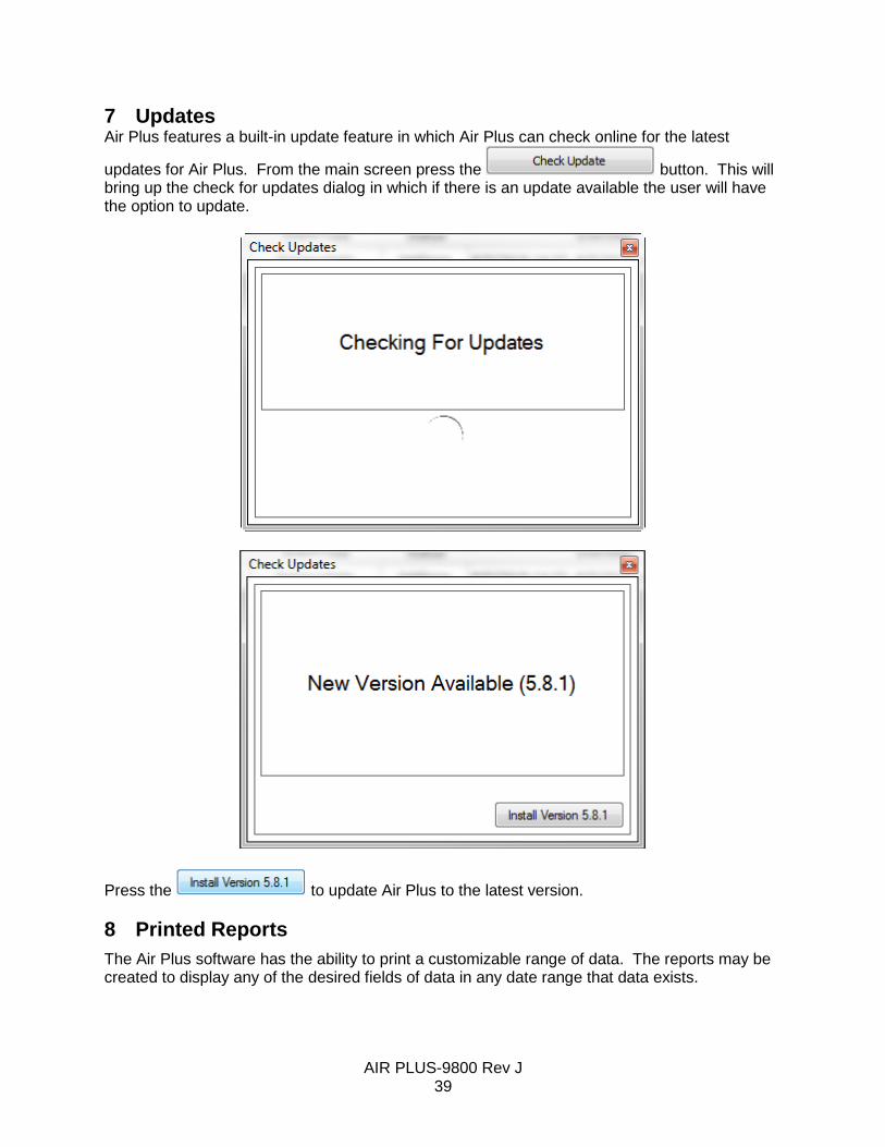
7 Updates Air Plus features a built-in update feature in which Air Plus can check online for the latest
updates for Air Plus. From the main screen press the button. This will bring up the check for updates dialog in which if there is an update available the user will have the option to update.
Press the to update Air Plus to the latest version.
8 Printed Reports
The Air Plus software has the ability to print a customizable range of data. The reports may be created to display any of the desired fields of data in any date range that data exists.

AIR PLUS-9800 Rev J 40
8.1 Creating Reports
From the main screen, select the station from which you wish to view data and press the
button. This will activate the station for data collection and reading. Press the
button near the bottom center portion of the window. This will bring up the report screen.
At the top of the screen select the starting and ending date ranges in the date selection fields. If you are printing hourly or shorter averages, you may also manually type in the time of day you wish to include in your report.
You may now select which parameters you would like to include in your report. In the Available Field frame, select the parameters that you wish to print. You may hold down the CTRL key to
select multiple entries. Pressing the (located between the Available Field and the Selected Field frames) will move your highlighted parameters to the Selected Field frame. Any parameter
listed in the Selected Field frame will be printed on the report. Pressing the will move all parameters from the Available Field frame to the Selected Field frame. You may also use the
and to remove items from the Selected Field frame.
The parameters in the Selected Field frame will be printed left to right on the printout, with the top of the list being printed first. If the parameters are not listed in the preferred print order, it is possible to rearrange them. Highlight a parameter in the Selected Field frame and then use the
and located in the center of the screen to change the position of that parameter in the list of items being printed.
The main heading for your report and a sub heading description may be entered in the lower right corner of the report screen. The default setting is for the Station Name to be the report

AIR PLUS-9800 Rev J 41
main heading and the sub heading is blank. The font sizes and types for all of the text on the report may be changed on the Font tab in the lower right corner.
Once your report is configured, it may be printed using the print features located at the top of the screen.
All data points that are flagged as No Data or Outlier will show as 0 value on a printed report and will be flagged with a ? to indicate it is not reliable and should be ignored.
8.2 Saving Report Templates
You may save the report configuration as a Report Template for rapid access in the future. Simply type the name of the template in the Report Template field and press the Save button located to the right of the field. The drop down arrow on the right hand side of this field allows quick access to all saved templates. Outdated templates may be deleted by selecting them and pressing the Delete button located to the right of the Save button.
9 Wind Rose Reports
The Air Plus software also has the ability to print a wind rose plot from the collected data. This report is often required by agencies reporting data to the EPA and can be created very simply with Air Plus.
9.1 Creating Reports
From the main screen, select the station from which you wish to view data and press the
button. This will activate the station for data collection and reading. Press the
button near the bottom center portion of the window. This will bring up the wind rose screen.

AIR PLUS-9800 Rev J 42
At the top of the screen select the starting and ending date ranges in the date selection fields. If you are printing hourly or shorter averages, you may also manually type in the time of day you wish to include in your report.
The wind speed and wind direction channels are selected by default. If there are multiple wind speed and/or direction channels, be certain the correct channels are selected for display. Time intervals, such as daily, hourly, etc. are selected in the Data tab located underneath the Channel tab. This section also allows you to choose between a 16 sector plot and an 8 sector plot.
Once your date range, channels, and data type are selected, press the green arrow button to the right of the date range selection fields to generate the report.
The title of the report may be changed if desired. Simply modify it in the title block above the plot so it appears as you wish it to be. It is the station name by default.
The colors indicating ranges of wind speed may be changed in the lower left corner using the scale tab. Selecting the more tab behind the scale tab allows for refining the appearance of the plot further, such as adjusting the width of the angles, the internal scale indicators, or the background gradient.
The report may now be printed using the print features located at the top of the screen.

AIR PLUS-9800 Rev J 43
10 Exporting and Importing Data
The Air Plus software is able to export data in standard comma separated (*.csv) format. It can also import existing data that has previously been exported by Air Plus in to a new station. In some cases, data from Micro Met Plus 2.2 can also be imported.
10.1 Exporting data
From the main screen, select the station from which you wish to export data and press the
button. This will activate the station for data collection and reading. Press the
button near the bottom center portion of the window. This will bring up the import/export screen.
The top half of the screen allows you to select your date ranges and parameters for importing or exporting using the same means to create reports discussed in the Printed Reports: Creating Reports section of this manual. The top right corner also has a selection marker for choosing whether you are exporting or importing data. Select the Export marker to export the desired data.
The Data Source select field determines the time interval for the data you are exporting.
Once all of your parameters are chosen, press the browse button located to the right of the File to Export To field. This will allow selection of the destination folder and naming of the exported file. Press the SAVE button to return to the import/export screen. Press the Execute button to the right of the date range selection fields to export the data.

AIR PLUS-9800 Rev J 44
10.2 Auto Export
You may wish to automatically export and store your data to a csv file on your local PC, network location, or ftp server. The Auto Export feature (enabled in your Queue) gives you this ability. See the Configuration: Defining a New Station for instructions on creating an Auto Export event in your Queue. As part of an Auto Export event, a data download will be performed first; a separate download event does not need to be created.
To create an Auto Export template, from the main screen, select the station from which you wish
to export data and press the button. This will activate the station for data
collection and reading. Press the button to bring up the import/export screen. There are three tabs in this window, Manual Execution, File Options, and CSV Data Options.
10.2.1 Manual Execution The first tab in the Auto Export window is for manual execution. This tab is used if you would like to manually performing an export of data following the rules in your chosen Export Template. After creating and/or editing your Auto Export template, select the desired working template,
specify the start date/time and end date/time, and then click on the button. The processing messages will be displayed on the Execution Log above. Additionally, all the steps of FTP communication will be displayed here; this may be helpful when troubleshooting a connection problem.

AIR PLUS-9800 Rev J 45
It is recommended that a manual execution be performed after creating a new template file to verify it is operating as intended.
10.2.2 File Options The second tab in the Auto Export window is for defining where your data file will be stored and how it shall be named. The Output Location will default to your *\MOI_DataBase\FileOutPut folder. If you would prefer a different folder, you may browse to it using the browse button to the right. Alternatively, you may type in a specific location, such as a network folder, if you are unable to find it using the browse feature.

AIR PLUS-9800 Rev J 46
To use the Send File to FTP option, check the box and enter your FTP Server details in the appropriate fields. A typical server may look like this:
Once you have set up your location and FTP Server details, the last step is to determine how your file shall be named. By default, the station name is used as the first part of the file name which is then followed by the date and time. The station name may be changed to anything you prefer. The date and time format is selected from the drop down menu. The text string after the % in the date/time drop box is the format for date/time value conversion; the % mark itself is not included. The text before % is for description purposes and will not appear in the file name. The date/time field may be removed from the file name by deleting the text and leaving it blank.
Note: The format selected for date and time will affect the creation of your data files. See the discussion in the Interaction of Formatting Options section of this manual for more details. Finally, if you would prefer to use a different file extension, you may change it from .csv to another appropriate extension, such as .txt. As you make define your file naming convention, a sample file name will be displayed at the bottom of the window.

AIR PLUS-9800 Rev J 47
10.2.3 CSV Data Options This final tab in the Auto Export window is for defining the formatting to be used when creating your data file.
Data Source – This should match the interval used in your data set Data Separator – This allows you to use a semicolon if your data uses a comma for a decimal point Decimal Point – Allows your data to use a comma instead of a period (or dot) for the decimal point. Selecting comma will force the data separator to use a semicolon. Data Period – Determines whether you will export all data stored since your last export or just the very last record collected. Append Data – Choose whether you will add your new data to the end of your existing file or erase your existing file and replace it with the new data set. Date Time Format – Use the drop down boxes to select the format you would like to use for your date and time information. If the Separator check box is checked, there will be a data separator splitting the time apart from the date, making them separate data fields.
The bottom portion of this tab allows you to select the data fields you would like to export and the order in which they should appear in the string. The arrow buttons here operate in the same way as described in the Printed Reports: Creating Reports section of this manual.

AIR PLUS-9800 Rev J 48
10.2.4 Interaction of Formatting Options The date/time selection (on the File Options tab), Data Period choice, and Append Data preferences interact with each other and can result in a variety of outputs. When the Date/Time option is used:
A new file will be created every time the smallest time interval changes. For example, if it is set to year/month/day/hour then a new file will be created every hour. If it is set to year/month, then a new file will be created every month, and so on. For the discussion below, assume we have selected year/month/day.
If Since Last Export is selected, then all new records since the last export will be put into a daily file. If Last Record is selected, then only the last record saved will be used. For example, if the logger stores 1-minute records and the last export was an hour ago, there should be 60 new records available. However, only the last one will be exported to the daily file and the previous 59 records will be ignored.
If Append To Existing File is selected, all exports made on the same day will append the new records to the end of the same file.
If Always Create New/Over Write is selected, the daily file will be erased and replaced with the new records being exported. This will happen every time data is exported on that day.
When the Date/Time is NOT used (it is left blank):
The file name will always be the same. It will not create a new file based on the time interval.
If Append To Existing File is selected, all records will be appended to the end
and accumulated in the same file. Over time, this can result in an extremely large
file.
If Always Create New/Over Write is selected, the file will be erased and replaced
with the new records being exported.

AIR PLUS-9800 Rev J 49
10.3 Importing data
Importing data to a station is a simple task.
From the main screen, select the station to which you wish to import data and press the
button. Press the button near the bottom center portion of the window to enter the import/export screen (shown above).
This time we will select the Import marker in the top right corner of the screen.
Select your parameters for the data to be imported using the same means to create reports discussed in section 5.1. It is important that the parameters selected for importation exactly match those parameters in the data set that is being imported. This includes placing them in the same order.
Once all of your parameters are chosen and properly arranged, press the browse button located to the right of the File to Import From field. This will allow selection of the source file. Press the OPEN button to return to the import/export screen. Press the Execute button to the right of the date range selection fields to import the data

AIR PLUS-9800 Rev J 50
Appendix A 466A Channel Parameters
Warning: Always make sure that critical Air Plus channel parameters (Data Type, Multiplier, Offset, and Full Scale Voltage) match the channel parameters of the data logger. This must be done before data is retrieved from the data logger. Failure to do so will cause incorrect data values to be stored in Air Plus.
The channel parameters for a 466A are located on the SENSOR setup screen. A typical screen is located below.
SETUP CHAN PARAMS
CHAN TYPE UNITS PREC MULT OFFSET
01 WS m/s 1 0060.0 000.0
SENSOR FS VOLT: 2.500
INV SLOPE:N VECT/SCALAR:S MODE:MANUAL
SAVE ID MODE EXIT
Transfer these channel parameters to the Air Plus Station Definition Channel screen for each channel. Map the channel parameters this way.
466A Air Plus
TYPE Channel Name
UNITS Unit
PREC Precision
MULT Multiplier
OFFSET Offset
FS VOLT Channel Full Scale Voltage
VECT/SCALAR Data Type
Channels parameters that are fixed and cannot be changes will be dimmed out.

AIR PLUS-9800 Rev J 51
Appendix B BAM-1020 Channel Parameters
Warning: Always make sure that critical Air Plus channel parameters (Data Type, Multiplier, Offset, and Full Scale Voltage) match the channel parameters of the data logger. This must be done before data is retrieved from the data logger. Failure to do so will cause incorrect data values to be stored in Air Plus.
The channel parameters for a BAM-1020 are located on the SENSOR setup screen. A typical screen is located below.
SETUP CHAN PARAMS
CHAN TYPE UNITS PREC MULT OFFSET
I1 Conc mg 3 01.000 -0.015
SENSOR FS VOLT: 2.500
INV SLOPE:N VECT/SCALAR:S MODE:AUTO ID
SAVE ID MODE EXIT
Transfer these channel parameters to the Air Plus Station Definition Channel screen for each channel. Map the channel parameters this way.
BAM-1020 Air Plus
TYPE Channel Name
UNITS Unit
PREC Precision
MULT Multiplier
OFFSET Offset
FS VOLT Channel Full Scale Voltage
VECT/SCALAR Data Type
Channels parameters that cannot be changed will be dimmed out.
Typically a temperature sensor is connected to channel 6 and set to Auto ID. Three type of temperature sensors are supported: BX-592, BX-596, or CARB. Below are the channel parameters for all.
Type Name Units Prec Data Type Mult Offset Full Scale
BX-592 AT C 1 SCALAR 80.0 -30.0 1.0
CARB AT C 1 SCALAR 100.0 -50.0 1.0
BX-596 AT C 1 SCALAR 95.0 -40.0 2.5

AIR PLUS-9800 Rev J 52
Appendix C E-BAM Channel Parameters
Warning: Always make sure that critical Air Plus channel parameters (Data Type, Multiplier, Offset, and Full Scale Voltage) match the channel parameters of the data logger. This must be done before data is retrieved from the data logger. Failure to do so will cause incorrect data values to be stored in Air Plus.
Only the E-BAM channel name parameters can be changed.
Channels parameters that cannot be changed will be dimmed out.

AIR PLUS-9800 Rev J 53
Appendix D E-Sampler Channel Parameters
Warning: Always make sure that critical Air Plus channel parameters (Data Type, Multiplier, Offset, and Full Scale Voltage) match the channel parameters of the data logger. This must be done before data is retrieved from the data logger. Failure to do so will cause incorrect data values to be stored in Air Plus.
The E-Sampler has a setting called ENGR UNITS found on the SETUP/ENGINEERING UNITS screen. It can be set to either METRIC or ENGLISH.
Air Plus initializes E-Sampler channel parameters to METRIC units for channels AT, BP and WS.
The METRIC and ENGLISH channel parameters are shown next.
Metric Channel Parameters
Channel Name Units Prec Data Type Mult Offset Full Scale
3 AT C 1 SCALAR -147.1 95.8 2.5
4 BP Pa 0 SCALAR 80000 30000 2.5
7 WS m/s 1 SCALAR 44.7 0.28 2.5
English Channel Parameters
Channel Name Units Prec Data Type Mult Offset Full Scale
3 AT F 1 SCALAR -264.78 204.44 2.5
4 BP inHg 1 SCALAR 23.62 8.86 2.5
7 WS mph 0 SCALAR 100.0 0.63 2.5

AIR PLUS-9800 Rev J 54
Appendix E Status Column Alarm Codes by Device
Product Status Description
466A C The unit was in calibration mode.
BAM-1020 T Tape transport error
C Beta count failure
D Membrane reading failure
P Excessive pressure drop
F Flow failure
N Nozzle failure
R Reference membrane failure
L Power failure
I Concentration calculation error
M Maintenance flag
U Telemetry fault
E External or Interface reset
E-BAM T Tape break (1)
C Beta count failure (2)
D Sensor failure (4)
P Pressure failure (8)
F Flow failure (16)
N Nozzle failure (32)
R Internal hardware failure (64)
L Low battery (128)
M Pump failure (512)
E-Sampler T Self-test failure (1)
C Span check error (2)
D Laser current failure (4)
P Pressure sensor failure (8)
F Flow failure (16)
R Internal hardware failure (64)
L Low battery failure (128)

AIR PLUS-9800 Rev J 55