air operated/external pilot solenoid · 2017-07-06 · vnc 1 4 vnc 2 4 note 1) no freezing note 2)...
TRANSCRIPT

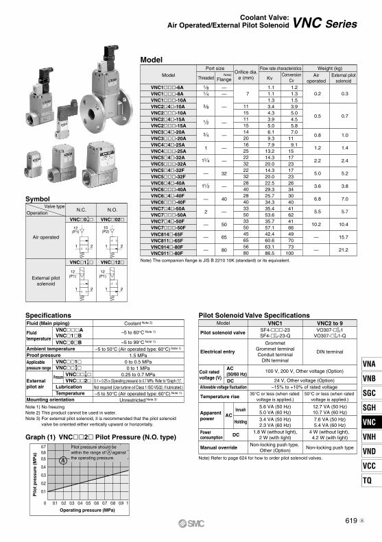
Coolant ValveVNC SeriesAir Operated/External Pilot Solenoid
Cylinder actuation by pilot air
Wide selection of port
size and variationsThreaded type (6A to 50A)
Flange type (32F to 80F)
Low water hammer
For details, refer to page 626.
Large valve capacity
Av factor 30 x 10-6 to 1600 x 10-6
(VNC1 to VNC7)
Cv factor 49 to 100
(VNC8 to VNC9)
[Option]
617
VNA
VNB
SGC
SGH
VNC
VNH
VND
VCC
TQ
VNC

VNC 15A 1
VNC 15A (Except valve size 8, 9)Air operated
External pilot solenoid 2
2
1
1
A
A
1
0
T
Valvesize
1
Valvesize
2 to 9
∗ Semi-standard
Nil: Non-locking push type
Nil: Non-locking push type
A: Non-locking push type A (projecting)
B: Slotted locking type B (tool required)
Coolant Valve:Air Operated/External Pilot Solenoid
VNC Series Note) CE-compliant: For D or
DZ only
[Option]
How to OrderSeal material
AB
NBR sealsFKM seals
Thread typeNilFNT
Rc G NPTNPTF
Bracket (Valve size: 1/2/3/4)Nil
B Note)
NoneWith bracket (VN-16)
Note) Only valve sizes 1, 2, 3 and 4. Shipped after assembled at our factory.Bracket part no. Valve size 1: VN1-A16 (with thread) Valve sizes 2 to 4: VN-16
2 to 4
Valve size Valve type Port size
Orificediameter
(mm)Symbol
Symbol
Symbol
11
N.C.0.5 MPa
N.O.1 MPa
N.C.1 MPa
PortsizeRc
ø15 (ø11)
ø7
ø20 (ø14)
2
16A8A10A10A15A20A25A32A
32F
40A
1 2 4
3ø25 (ø16)4
ø32 (ø22)5
ø40 (ø28)6
Values in parentheses are N.C. at 1 MPa.
40F
250Aø50 (ø33)7
50F
65Fø65 (ø45)8
80Fø80 (ø56)9
1 81 43 83 81 23 4
1 4
1 1 2
1 B1 4Flange
1 B1 2Flange
2BFlange
3BFlange
2 B1 2Flange
Rated voltage
110 VAC 50/60 Hz200 VAC 50/60 Hz100 VAC 50/60 Hz
Nil Air operated
220 VAC 50/60 Hz24 VDC12 VDC
3∗21
4∗56∗7∗ 240 VAC 50/60 Hz
∗ Semi-standardFor other rated voltages, please consult with SMC.
Electrical entry/With light/surge voltage suppressor
Symbol
Grommet terminalGrommet with surge voltage suppressor
Grommet
Electrical entry
Grommet terminal with light/surge voltage suppressorConduit terminal
Conduit terminal with light/surge voltage suppressorDIN terminal
DIN terminal with light/surge voltage suppressor
EGSG
EZTTZDDZ
D DIN terminalDIN terminal with light/surge voltage suppressorDZ
CE-compliant
Manual override
∗
∗
CE-compliant
Note) Electrical entry: D or DZ only
NilQ
—CE-compliant
Valvesize
1
Valvesize
2 to 9
SymbolValvesize
1
Valvesize
2 to 9Electrical entry
618
21 12
1 212
12(P1)
10(P2)
12(P1)
12(P1)
VNC Series
Symbol
Graph (1) VNC2 Pilot Pressure (N.O. type)
Note) The companion flange is JIS B 2210 10K (standard) or its equivalent.
Valve typeOperation
N.C. N.O.
Air operated
External pilotsolenoid
VNC0 VNC0214
VNC1 VNC1214
Fluid temperature
Applicable pressure range
Externalpilot air
Pressure
Fluid (Main piping)VNCAVNC1BVNC0B
VNC1
VNC2
Ambient temperatureProof pressure
Mounting orientation
LubricationTemperature
Coolant Note 2)
–5 to 60°C Note 1)
–5 to 50°C (Air operated type: 60°C) Note 1)
1.5 MPa0 to 0.5 MPa0 to 1 MPa
0.25 to 0.7 MPa0.1 + 0.25 x (Operating pressure) to 0.7 MPa Refer to “Graph (1)”. Not required (Use turbine oil Class 1 ISO VG32, if lubricated.)–5 to 50°C (Air operated type: 60°C) Note 1)
Unrestricted Note 3)
–5 to 99°C Note 1)
VNC 14
VNC 24
Note 1) No freezing Note 2) This product cannot be used in water.Note 3) For external pilot solenoid, it is recommended that the pilot solenoid
valve be oriented either vertically upward or horizontally.
SpecificationsModel
Pilot solenoid valve
Electrical entry
Coil ratedvoltage (V)
AC(50/60 Hz) DC
DC
Allowable voltage fluctuation
Temperature rise
Apparent power
ACInrush
Holding
Powerconsumption
Manual override
100 V, 200 V, Other voltage (Option)
24 V, Other voltage (Option)–15% to +10% of rated voltage
5.6 VA (50 Hz)5.0 VA (60 Hz)
3.4 VA (50 Hz)2.3 VA (60 Hz)
12.7 VA (50 Hz)10.7 VA (60 Hz)
7.6 VA (50 Hz)5.4 VA (60 Hz)
35°C or less (when rated voltage is applied.)
1.8 W (without light),2 W (with light)
4 W (without light), 4.2 W (with light)
Non-locking push type, Other (Option)
Non-locking push type
Note) Refer to page 624 for how to order pilot solenoid valves.
Pilot Solenoid Valve Specifications
50°C or less (when rated voltage is applied.)
Pilot pressure should be within the range of A against the operating pressure.A
0 10.1
0.1
0.2
0.3
0.4
0.50.60.7
0.2 0.3 0.4 0.5 0.6 0.7 0.8 0.9
Pilo
t p
ress
ure
(M
Pa)
Operating pressure (MPa)
VNC1SF4--23SF4-D
DZ-23-Q
VNC2 to 9VO307-D
DZ1VO307-D
DZ1-Q
GrommetGrommet terminalConduit terminal
DIN terminal
DIN terminal
Coolant Valve:Air Operated/External Pilot Solenoid
Port size Flow rate characteristics Weight (kg)Air
operatedExternal pilot
solenoid
Orifice dia.ø (mm)Model
1 81 4
3 8
1 2
3 4
1 4
1 2
1
1
VNC1-6AVNC1-8AVNC1-10AVNC24-10AVNC2-10AVNC24-15AVNC2-15AVNC34-20AVNC3-20AVNC44-25AVNC4-25AVNC54-32AVNC5-32AVNC54-32FVNC5-32FVNC64-40AVNC6-40AVNC64-40FVNC6-40FVNC74-50AVNC7-50AVNC74-50FVNC7-50F
ThreadedNote)
Flange
—
—
—
50
—
40
—
32
—
—
—
—
—— 7
Kv
1.1 1.1 1.3 3.4 4.3 3.9 5.0 6.1 9.3 7.913.214.320.014.320.022.529.325.734.335.453.635.757.142.460.663.186.5
ConversionCv
1.2 1.3 1.5 3.9 5.0 4.5 5.8 7.0 11 9.1 15 17 23 17 23 26 34 30 40 41 62 41 66 49 70 73 100
0.2
0.5
0.8
1.2
2.2
5.0
3.6
6.8
5.5
10.2
—
—
—
2
—
—
1
Model
VNC814-65FVNC811-65FVNC914-80FVNC911-80F
65
80
111511151420162522322232284028403350335045655680
0.3
0.7
1.0
1.4
2.4
5.2
3.8
7.0
5.7
10.4
15.7
21.2
619
VNA
VNB
SGC
SGH
VNC
VNH
VND
VCC
TQ
VNC
A

N.C.
u
o
i
t
r
w
u
y
e
r
q
t
i
VNC Series
Construction
o
i
t
r
w
u
y
e
r
q
t
i
In the case of 32A to 50A
N.C. (Return spring normally closed) When the pilot solenoid valve o is not energized (or when air is exhausted from the port 12(P1) for air operated type), the valve body r connected to the piston y is closed by the return spring u. When valve body opensWhen the pilot solenoid valve is energized (or when pressurized air enters through the port 12(P1) of the air operated type), the pilot air that has entered under the piston moves upward to open the valve element. When valve body closesWhen the power to the pilot solenoid valve is turned off (or when fluid is exhausted from the port 12(P1) of the air operated type), the pilot air under the piston is exhausted, and the return spring closes the valve element.
Port 12(P1) Port 10(P2)
Port 1 Port 2
N.O.
N.O. (Return spring normally open) In contrast with the N.C., when the pilot solenoid valve is not energized (or when air is exhausted from the port 10(P2) of the air operated type), the valve body is opened by the return spring. When the pilot solenoid valve is energized (or when pressurized air enters through the port 10(P2) of the air operated type), the valve body closes.
Note) 3, 5 components determine the valve composition.
No.
23
1Description
Aluminum alloyIron
MaterialCast iron
4 Stainless steel
6 Aluminum alloy7 Piano wire8 Stainless steel
Platinum silver paintedSeal material (NBR, FKM)
NotePlated
5 NBR, FKM 32A to 50A are O-ring.
9 —
Cover assemblyBody assembly
Plate assemblyValve elementValve coverPiston assemblyReturn springSpiral pinPilot solenoid valve
Component Parts
No.
3FKMNBR
NBR VN2-A3CA
Part no.
VN2-A3CBVN2-12CAVN2-12CB
VN3-A3CAVN3-A3CB
VN4-A3CAVN4-A3CBVN4-12CAVN4-12CBVN4-60-1 VN5-60-1 VN6-60-1 VN7-60-1Refer to Note 2)VN2-60-1
VN5-A3CAVN5-A3CB
AS568-010 AS568-011 AS568-012
VN6-A3CAVN6-A3CB
VN7-A3CAVN7-A3CB
FKM
Plate ass'ySeal
materialSeal
material5Valve cover(32A to 50A are O-ring.)
8 Spiral pin
Description VNC1-6A, 8A, 10A
9 Pilot solenoid valve SF4--23 VO307-DDZ1 (Refer to page 624 for part no.)
VNC2-10A, 15A
VNC3-20A
VNC4-25A
VNC5-32A, 32F
VNC6-40A, 40F
VNC7-50A, 50F
No.
3FKMNBR
Part no.
Plate assemblySeal
material8 Spiral pin
Description
VN7-60-19 Pilot solenoid valve VO307-D
DZ1 (Refer to page 624 for part no.)
VN8-A3CAVN8-A3CB
VNC811-65F VNC911-80F
VN9-A3CAVN9-A3CB
Replacement Parts
Replacement Parts: Applicable Flange
Refer to Note 1)
Note 1) Request factory repair.
Note 2) For VNC3 use VN3-60-1, and for VNC34 use VN2-60-1.12
620

ModelVNC1-6AVNC1-8AVNC1-10A
Main port 1, 21 81 43 8
Threaded Type/Port size: 6A, 8A, 10A
VNC Series
∗ In the case of “EZ” or “TZ” or “DZ”, the length is longer by 9 mm.
Pilot port 12(P1)2 x (Back side 10(P2))8
1Manual override(Non-locking push type)
Pg.9
65 (Grommet terminal: E)∗
70 (Conduit terminal: T) ∗74 (DIN terminal: D) ∗
Main port 1 (Back side port 2)
Port size: refer to table below
45
27
18
2 x ø4.5
231
24
(1.6
)12
.539
.56
Bracket
2 x M4 x 0.7 depth 7
504018
127
(Con
duit
term
inal
: T, D
IN te
rmin
al: D
)
106.
5 (G
rom
met
term
inal
: E)
106.
7 (G
rom
met
: G)
63 (
Air
oper
ated
)
Coolant Valve:Air Operated/External Pilot Solenoid
621
VNA
VNB
SGC
SGH
VNC
VNH
VND
VCC
TQ
VNC
A

32
15
P2P1
P1
VNC2-10AVNC2-15AVNC3-20AVNC4-25A
A63638090
B42425060
C29293540
D14.514.517.520
E72.572.584100
F80.580.592108
H95.395.3100.3101.3
J Note)
162.5 (164.5)162.5 (164.5)
174 (176)190 (192)
K L52526272
M26263136
N4.54.55.56.5
P24.324.328.333.3
Q2.32.32.32.3
R25253035
S34344349
5555
60.573
Model
VNC5-32AVNC6-40AVNC7-50A
Main port1, 2
Pilot port12(P1), 10(P2) A
105120140
B
7796113
C
536074
D
26.53037
E
120.5137160
F
202424
H
129.5147170
J Note)
211.5 (213.5)229 (231)252 (254)
K
556374
1 41 2
11
2
1 81 41 4
Threaded Type/Port size: 10A, 15A, 20A, 25A
Threaded Type/Port size: 32A, 40A, 50A
Note) ( ): CE-compliant product (-Q)
Note) ( ): CE-compliant product (-Q)
HA
R
F (
Air
oper
ated
)
J (E
xter
nal p
ilot s
olen
oid)
4 x øM
KL Pg9
Applicable cable O.D.ø6 to ø8
Light/surge voltage suppressor(For DZ)
Manual override (Non-locking push type)
N
P
BC
DS
Q
E
Pilot port 12(P1)2 x (Back side 10(P2))
AK
H (
Air
oper
ated
)
J (E
xter
nal p
ilot s
olen
oid)
Manual override (Non-locking push type)
Light/surge voltage suppressor(For DZ)
Applicable cable O.D.ø6 to ø8
Pg9
Pilot port 12(P1), 10(P2)Port size: refer to table belowF
ED
BC
Bracket
81
VNC Series
Main port 1(A) [Back side 2(B)]Port size: refer to table below
Model Main port 1, 23 81 23 4
1
Main port 1(A) [Back side 2(B)]Port size: refer to table below
622A
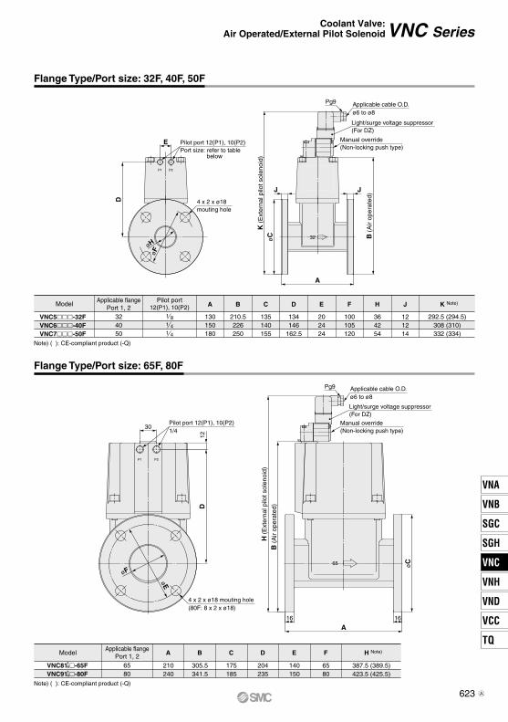
32
P1 P2
65
P1 P2
Model
VNC5-32FVNC6-40FVNC7-50F
Applicable flangePort 1, 2
Pilot port12(P1), 10(P2) A
130150180
B
210.5226250
C
135140155
D
134146
162.5
E
202424
F
100105120
H
364254
J
121214
K Note)
292.5 (294.5)308 (310)332 (334)
324050
1 81 41 4
Model
VNC81 -65FVNC91 -80F
Applicable flangePort 1, 2
6580
A
210240
B
305.5341.5
C
175185
D
204235
E
140150
F
6580
H Note)
387.5 (389.5)423.5 (425.5)
1414
Note) ( ): CE-compliant product (-Q)
Note) ( ): CE-compliant product (-Q)
B (
Air
oper
ated
)JJ
A
øC
K (
Ext
erna
l pilo
t sol
enoi
d)
Pg9 Applicable cable O.D.ø6 to ø8
Light/surge voltage suppressor(For DZ)
Manual override (Non-locking push type)
4 x 2 x ø18 mouting hole
Pilot port 12(P1), 10(P2)Port size: refer to table
below
E
D
D12
Pilot port 12(P1), 10(P2)1/4
30
øC
A1616
B (
Air
oper
ated
)
H (
Ext
erna
l pilo
t sol
enoi
d)
Pg9 Applicable cable O.D.ø6 to ø8
Light/surge voltage suppressor(For DZ)
Manual override (Non-locking push type)
4 x 2 x ø18 mouting hole(80F: 8 x 2 x ø18)
øF
øE
øF
øH
VNC Series
Flange Type/Port size: 65F, 80F
Flange Type/Port size: 32F, 40F, 50F
Coolant Valve:Air Operated/External Pilot Solenoid
623
VNA
VNB
SGC
SGH
VNC
VNH
VND
VCC
TQ
VNC
A
VNC Series
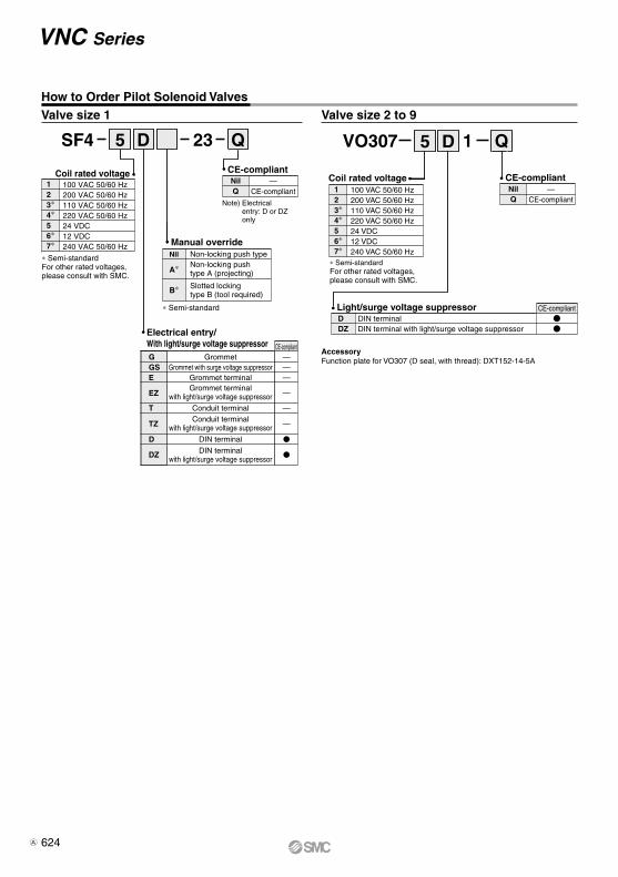
How to Order Pilot Solenoid ValvesValve size 1 Valve size 2 to 9
100 VAC 50/60 Hz200 VAC 50/60 Hz110 VAC 50/60 Hz220 VAC 50/60 Hz24 VDC12 VDC240 VAC 50/60 Hz
123∗4∗56∗7∗
Coil rated voltage
∗ Semi-standardFor other rated voltages, please consult with SMC.
Electrical entry/With light/surge voltage suppressor
E Grommet terminalGS Grommet with surge voltage suppressorG Grommet
EZGrommet terminal
with light/surge voltage suppressor
T Conduit terminal
TZConduit terminal
with light/surge voltage suppressor
D DIN terminal
DZ DIN terminalwith light/surge voltage suppressor
———
—
—
—
CE-compliant
Manual override
∗ Semi-standard
Non-locking push typeNon-locking push type A (projecting)
Slotted locking type B (tool required)
Nil
A∗
B∗
CE-compliant
Note) Electrical entry: D or DZ only
AccessoryFunction plate for VO307 (D seal, with thread): DXT152-14-5A
Coil rated voltage
∗ Semi-standardFor other rated voltages, please consult with SMC.
123∗4∗56∗7∗
100 VAC 50/60 Hz200 VAC 50/60 Hz110 VAC 50/60 Hz220 VAC 50/60 Hz24 VDC12 VDC240 VAC 50/60 Hz
Light/surge voltage suppressor DDZ
DIN terminalDIN terminal with light/surge voltage suppressor
CE-compliant
1 QSF4 5 D 5 D23
CE-compliant—
CE-compliantNilQ
—CE-compliant
NilQ
Q VO307
624A

Caution
Design Mounting Direction of Pilot Solenoid Valve
Warning Warning1. Extended periods of continuous energizationIf a valve is continuously energized for long periods, heat generation of the coil may result in reduced performance and shorter service life. This may also have an adverse effect on the peripheral equipment in proximity. Should a valve be continuously energized for long periods, or its daily energized state exceeds its non energized state, please use valve with DC specifications. Additionally, when using with AC, energizing for long periods of time continously, select the air-operated valve and use the continuous duty type of the VT307 for a pilot valve.
With external pilot solenoids, the pilot solenoid valves are not splash proof specifications, and so care must be taken not to get fluid on oneself such as when performing maintenance.
CautionDirection of mounting
When replacing a valve, if an external pilot solenoid valve is mounted in the wrong direction, it may malfunction or leak air.
Installing a silencer to the exhaust port and the bleed port is recommended for noise reduct ion and for dust entry prevention.
External Pilot
Pilot port piping12(P1) and 10(P2) piping should be as follows according to the model.
Fluid quality
CautionPlease note that using fluids that contain foreign mterial (especially hard objects like glass chips), may cause damage to the valve, will reduce sealing performance, and may cause early failure.
Mounting
Warning1. Do not apply external force to the coil section.
When tightening is performed, apply a wrench or other tool to the outside of the piping connection parts.
2. Do not warm the coil assembly with a heat insulator, etc.Use tape, heaters, etc., for freeze prevention on the piping and body only. They can cause the coil to burn out.
3. Avoid sources of vibration, or adjust the arm from the body to the minimum length so that resonance will not occur.
4. When mounted in the vertical downward direction, foreign matter can remain in the plate assembly part if there are foreign matters in the coolant. For this reason, avoid mounting in the ver t ical downward direction as much as possible.
Wiring
Caution1. Applied voltage
When electric power is connected to a solenoid valve, be careful to apply the proper voltage. Improper voltage may cause malfunction or coil damage.
2. Confirm the connections.After completing the wiring, confirm that the connections are correct.
Piping
CautionWhen high temperature fluids are used, use fittings and tubing with heat resistant features. (Self-align fittings, PTFE tubing, Copper tubing, etc.)
Port
Air operated Solenoid
VNC0 14 VNC02 VNC1
124
12(P1)
External pilot Bleed port External pilot
10(P2)
Bleed port External pilot Pilot exhaust
VNC SeriesSpecific Product Precautions 1Be sure to read this before handling the products.Refer to back page 50 for Safety Instructions and pages 17 to 19 for 2 Port Solenoid Valve for Fluid Control Precautions.
625
VNA
VNB
SGC
SGH
VNC
VNH
VND
VCC
TQ
VNC

VNC SeriesSpecific Product Precautions 2Be sure to read this before handling the products.Refer to back page 50 for Safety Instructions and pages 17 to 19 for 2 Port Solenoid Valve for Fluid Control Precautions.
15A
20A
25A
32AF
65F50A
F
80F
40AF
8A 25A
15A20A
65F80F
40AF
50AF
32AF
Water Hammer Characteristics
Calculating the Flow Velocity
v = 21.2 x Q/d2
(Symbol)v: flow velocity (m/s)Q: flow rate (L/min) d: piping inner diameter (mm)
VNC1 (N.C. 0.49 MPa)Conditions: Piping 30 m Steel tube, total pressure 0.49 MPa VNC4 (N.C. 0.97 MPa)
Conditions: Piping 30 m Steel tube, total pressure 0.97 MPa
Pea
k pr
essu
re a
t val
ve c
lose
d (M
Pa)
Flow velocity (m/s)
1
0.8
0.6
0.4
0.2
01 2 3 4 5
Pea
k pr
essu
re a
t val
ve c
lose
d (M
Pa)
Flow velocity (m/s)
2.5
2
1.6
1.2
0.8
0.4
01 2 3 4 65
626