air lubrication technology - american bureau of shipping · 2019-11-12 · skin frictional...
TRANSCRIPT

1 | AIR LUBRICATION TECHNOLOGY
Air Lubrication Technology April 1, 2019

2 | AIR LUBRICATION TECHNOLOGY
AIR LUBRICATION TECHNOLOGY
OVERVIEW In 2018, the International Maritime Organization released an initial strategy on the reduction of greenhouse gas emissions from ships with a clear framework to reduce ship emissions. In an effort to lower carbon emissions and to comply with increasing Energy Efficiency Design Index (EEDI) Phase III levels, various energy saving technologies, such as air lubrication, have been developed to meet the industry need. Air lubrication systems are recognized by IMO as a Category B-1 “Innovative Energy Efficiency Technology” as described in MEPC.1/Circ.815. This document provides an introduction to air lubrication technology for shipbuilders, shipowners, and other interested parties by presenting a summary of reported full-scale sea trials and current developments.
Figure 1: IMO MEPC.1/Circ. 815 Annex Schematic illustration of an air lubrication system
BACKGROUND One of the earlier applications using air bubbles on vessels was the Prairie/Masker Air System developed by the National Defense Research Committee in US Navy Laboratories since post World War II (Domenico, 1982). The Masker system emitted air bubbles under the hull, concealing engine room noise. The Prairie system emitted bubbles around the propeller. Both systems were envisioned to silence the ship acoustically, thus making less detectable by sonar. Scientists and scholars later became interested in air lubrication technology for its potential to reduce drag resistance on the hull. In ship resistance, the three main components are frictional resistance, form resistance and wave resistance. For higher speed displacement vessels, the frictional resistance is approximately 40%, but for low speed displacement vessels, the frictional resistance is the dominant contributor and can reach 85% of the total resistance. For low-speed vessels, a reduction on the frictional resistance would result in an even higher reduction in fuel

3 | AIR LUBRICATION TECHNOLOGY
consumption in addition to what is achieved by the traditional optimization of the ship’s hull form, addressing the form resistance and wave resistance components. Skin frictional resistance depends on the wetted surface area of a ship. Air lubrication technology can reduce this frictional drag for vessels, especially since this technology does not introduce major changes in hull form and the air injection rate can be adjusted. Without major changes in hull form or change in operational speed, the form and wave resistance are mostly fixed and only frictional drag is reduced. Air lubrication is achieved by pumping air beneath the hull, reducing the area of hull in direct contact with the liquid flow, or in the case of discrete bubbles, by modification of momentum transport and average density in the boundary layer. There are three major categories of air lubrication technology being studied now: Bubble Drag Reduction (BDR), Air Layer Drag Reduction (ALDR), and Partial Cavity Drag Reduction (PCDR).
Bubble Drag Reduction (BDR) The more efficient Bubble Drag Reduction uses very small or even micro-sized bubbles. The size of the these bubbles is generally less than 0.1 mm. However, micro-bubbles can be difficult to produce on a full-scale ship, and are less effective at low speeds due to buoyancy. As bubbles grow in size they can no longer maintain their spherical shape, making them prone to deform in turbulent flows. There is currently no well-established theory on the mechanisms of skin friction reduction by bubbles. One mechanism which appears to be agreed on by researchers is that the addition of bubbles to a liquid effectively reduces the liquid density, hence the Reynolds stress, resulting in a skin friction reduction. Other two possible mechanisms are:
• The turbulence suppression effect, wherein the bubbles suppress the turbulence in the boundary layer which reduces skin friction
• Bubbles decrease the effective viscosity of the flow due to the increase of the void fraction
Early pioneers experimenting with bubble drag reduction were McCormick and Bhattacharyya (1973) and Madavan et al. (1985). The experiment by McCormick and Bhattacharyya measured the drag force of a fully submerged body layered with hydrogen bubbles created by electrolysis. As the test body was towed at a constant speed, the skin friction reduction increased to 80% with the presence of micro-bubbles. Madavan et al. used the boundary layer of the test section of a wall tunnel with air injection from a porous plate. The national Dutch research project “Project Energy-saving air-Lubrication Ships” (PELS) was formed in 1999 to study the three air lubrication techniques, air bubble, air layer and air cavity. PELS studied numerical analysis of these techniques verified with model testing results. The results showed 3-10% average net energy saving in calm water. Two follow up projects (PELS 2 and EU-SMOOTH) were formed to further investigate the effects of air cavity and air bubble/air layer technology, respectively. Both projects focused on inland and coastal ships and conducted full-scale demonstrator tests.

4 | AIR LUBRICATION TECHNOLOGY
Mitsubishi Air Lubrication (MALS) Mitsubishi Air Lubrication System (MALS) was one of the first commercial air lubrication systems developed in the marine industry by the Japanese Shipbuilder Mitsubishi Heavy Industries (MHI), based on research developed since the 1980s in Japan. The MALS is a patented air lubrication system using the BDR method. MHI developed their own turbo blowers specifically used for the MALS, named Mitsubishi Turbo-blower for air lubrication. R&D Engineering - Winged Air Induction Pipe System (WAIP) Winged Air Induction Pipe (WAIP) comprises a series of small air chambers fitted with a foil for ultra-fine micro-bubble generation and was developed in Japan by Yoshiaki Takahashi and Professor Yuichi Murai. The research was conducted by scholars in Japanese universities beginning in 1998. The WAIP system has been the subject of various tests and is marketed via R&D Engineering Inc. Samsung Heavy Industries SAVER System (SAVER Air) Samsung Heavy Industries (SHI) developed an air lubrication system, referred as the SAVER system. The SAVER system uses a series of air dispensers installed on the bottom of the ship to spray air bubbles that form an air carpet at the bottom of the ship to reduce frictional drag resistance. Silverstream System Its origins lie in the DK Group, which applied large air cavities to reduce frictional drag. The company evolved into Silverstream Technologies in 2014 to further the commercialization of its patented air lubrication technology using smaller air chambers. The Silverstream system employs their patented air release units in the hull to create a layer of micro-bubbles to reduce frictional drag resistance. Foreship Air Lubrication System (Foreship ALS) Foreship, a Finnish ship design and engineering company established in 2002 developed an air lubrication system with air dispensers contained in a box to be added to the underside of the hull, which Foreship has optimized hydrodynamically and stated that it would not increase skin friction when the air lubrication system is not in use.
Air Layer Drag Reduction (ALDR) After many years of studying the BDR method, the focus of the air lubrication method extended to the air layer. When sufficient air is injected into the near-wall region of a turbulent boundary layer of water, the injected air will coalesce to form a continuous or nearly continuous layer of air separating the solid surface from the water flow. When the injected air increases, the coalesced air layer is able to maintain a fully continuous air layer covering a larger wetted surface and subsequently results in a greater skin friction drag reduction. In 2006, Sanders et al. performed a series of experiments in the US Navy’s William B. Morgan Large Cavitation Channel with a smooth flat plate and observed that at low speeds and high air injection rates, a layer of air would form on the underside of the flat plate model and persist

5 | AIR LUBRICATION TECHNOLOGY
along its entire length. Such air layers exhibited prominent drag reduction and offered an alternative air lubrication method from BDR. Researchers at the University of Michigan in 2008, led by Elbing et al., focused specifically on ALDR. Their experiments consisted of three separate test programs using rigid flat plate models and were conducted at the US Navy’s William B. Morgan Large Cavitation Channel as well. It was observed in the experiment that drag reduction increases with the air injection rate and decreases rapidly with the increase in downstream distance. Ceccio et al. (2012) suggested the experiment on the Pacific Seagull may have reached the ALDR region, where the injected air is strong enough to form an air layer. Ceccio et al. also suspected the MHI experiment by Mizokami et al. on vessel MV Yamatai may have reached the ALDR region as well. A series of tests for a flat plate and model of a 66 K DWT wide beam Supramax bulk carrier for resistance and self-propulsion were conducted in a towing tank in the Samsung Ship Model Basin by Jang et al., (2014). Jang et al was interested in ALDR and compared transitional air layer drag reduction and air layer drag reduction on both flat plate and bulk carrier models. The net power saving from ALDR was estimated to be approximately 5-6%. Peifer et al. (2018) studied the combination of a superhydrophobic surface (SHS) and air layer for drag reduction on a flat plate. The test results of Peifer et al. showed a significant reduction in the air flux required to maintain an air layer for ALDR and shows potential to make ALDR a much more economical solution.
Partial Cavity Drag Reduction (PCDR) The partial cavity concept utilizes a recess or cavity on the hull bottom where air is injected from inside the hull so that an inflated air cavity is formed and persists to the rest of the hull, separating the hull from with water, therefore reducing frictional resistance. The air layer in the cavitating flow in the cavity is much thicker than the turbulent boundary layer on the ship hull and requires smaller air injection rate to maintain the air layer than BDR or ALDR. A partial cavity study was commenced at the Krylov Shipbuilding Research Institute in the early 1960s with an initial focus on river vessels and barges, based on linearized 2D cavitation flow theory. They developed several ships with partial air cavities, referred to as air cavity ships. Since 1980s fast displacement vessels were investigated with 3D linearized theory. Later in the 1990s semi-planning catamarans, monohull fast marine passenger/ RORO vessels and high-speed yachts were investigated and tested in Russia. In the 2000s fast containership models were included in air cavity ship testing, and Sverchkov (2010) explored different hull profiles that would optimize the cavity shapes to further reduce drag resistance. Large scale experiments were carried out by Makiharju et al. (2010) on ventilated partial cavity flows at high Reynolds numbers to investigate the capacity of Partial Cavity Drag Reduction (PCDR) on ship hulls. The same flat plate model used by Elbing et al. was fitted with a backward facing step and cavity closure surface at the trailing end for the PCDR experiment. Tests of different combinations of cavity surfaces of the flat plate were carried out to find the

6 | AIR LUBRICATION TECHNOLOGY
optimum condition. The results showed that the air injection rate was about the same for initiating air layers and air cavities. The air injection rate needed to maintain the air cavity was only one third compared to maintaining an air layer. Slyozkin et al. (2014) conducted an experiment on flat plates with a backwards facing step at the upstream end and tests with various flow speeds and air injection rates in the Emerson Cavitation Tunnel. At the optimum condition, Slyozkin et al. was able to achieve a 26% reduction in drag. Contrary to bubble and air layer methods, the experiment showed that a lower air injection rate is needed for the generation and maintenance of the air cavities, and once the cavities were established in the flow, increasing air injection rate was not needed because it did not sginificantly reduce drag. This confirmed the observations seen in other experiments proving an air cavity could be the more economical method than air layer or bubbles. Following the report by Slyozkin et al., Butterworth et al. (2015) took it one step further to investigate the same concept on a model of an existing containership. The test results showed no significant impact on the static stability of the vessel when introducing the air cavity. The net energy saving suggested from the model testing ranged from 4% to 16%. Damen’s Air Chamber Energy Saving (ACES) System The Air Chamber Energy Saving (ACES) system is an air cavity lubrication system developed by Damen Ship and initiated as a PELS 2 Project. Air cavity chambers are fitted on the flat bottom of a vessel where air is fed into the chambers to separate the water from the bottom hull.
APPLICATIONS Up to 2018, 23 vessels were identified to have air lubrication system installed on board. They represent a large variety of vessel types and sizes as shown in Figure 2 and Figure 3.
Figure 2 : Vessel Types Installed with Air Lubrication Systems
0
1
2
3
4
5
6
BulkCarrier
CementCarrier
ChemicalTanker
Container Ferry GeneralCargo
HeavyLoad
Carrier
LNGCarrier
RiverBarge
RiverTanker
HeavyCargoCarrier
Cruise

7 | AIR LUBRICATION TECHNOLOGY
Figure 3 : Length Overall, Beam, and Draft of Vessel Installed Air Lubrication Systems
Recent Delivered Vessels Recently delivered vessels installed with air lubrication system are mostly cruise ships. Sea trial results including energy savings from air lubrication system are not yet published.
Table 1 : Recently delivered vessels with air lubrication system installed
Year Vessel Type Overall Length (m) Beam (m) Draft (m) System 2015 Quantum of the Sea Cruise 348.1 49.5 8.8 Foreship 2016 AIDAprima Cruise 300 37.6 8 MHI 2017 AIDAperla Cruise 300 37.6 8 MHI 2017 Norwegian Joy Cruise 333.5 48 8.7 Silverstream 2018 Diamond Princess Cruise 290.2 37.5 8.5 Silverstream
Vessels Under Contract Several companies announced their plan to install an air lubrication system on vessels, including Samsung Heavy Industries and Silverstream.
Table 2 : Under contract vessels for air lubrication system
Date Company Vessel Vessel Owner Jan, 2018 SHI (1) 23000 TEU super large container vessel MSC Aug, 2018 SHI (2) LNG carriers Celsius Tanker Dec, 2018 Silverstream (12) RORO carriers Grimaldi Group
Full-Scale Sea Trials Summary The overview of the performance of air lubrication systems presented is solely based on the information reported in the referenced literature. A total of 18 full scale performance tests between 2002 and 2015 were identified, and the sea trial details can be found in the Appendix. The net energy savings reported range approximately between 4% to 10%.
0
10
20
30
40
50
60
70
0
50
100
150
200
250
300
350
400
Beam
and
Dra
ft (m
)
Leng
th O
vera
ll (m
)Overall Length (m) Beam (m) Draft (m)

8 | AIR LUBRICATION TECHNOLOGY
The net savings from air lubrication is difficult to determine and estimate. Sea trial data were not collected and analyzed as required for EEDI trials given that many of the reported vessels were not subject to compliance with EEDI regulations at time of delivery.
EEDI CONSIDERATIONS In the IMO Energy Efficiency Design Index (EEDI) framework, air lubrication is considered as one of the “Innovative Energy Efficiency Technologies” that can improve energy gains through lowering the ship’s skin drag resistance. In 2013, the Marine Environment Protection Committee (MEPC), at its 65th session, agreed to circulate MEPC.1/Circ. 815, the 2013 Guidance on Treatment of Innovative Energy Efficiency Technologies for Calculation and Verification of the Attained EEDI. It should be noted that this is an interim guidance document which will evolve over time by experience gained as a result of use of these technologies.
Calculations: The attained ship EEDI is a measure of ship energy efficiency as characterized by the amount of CO2 produced as function of the transport work by a ship. It is calculated using the formula below (MEPC.1/Circ.815)):
The MEPC.1/Circ. 815 Guidance categorizes Innovative Energy Efficiency Technologies into 3 categories based their characteristics and effects on the EEDI formula. Air lubrication is classified as Category B-1 for technologies that reduce the propulsion power but do not generate electricity and can be used at any time during vessel’s operation. In effect, the power reduction is through adjustment to the 5th term in the numerator of the EEDI formula.
Verification In the verification scheme, final verification of the EEDI of ships fitted with air lubrication system is to be conducted at sea trial. The procedure to be followed should be in accordance with the 2014 IMO Guidelines on Survey and Certification of EEDI by MEPC.1/Circ.855 and MEPC.1/Circ.815. There are two steps to the verification of air lubrication system, preliminary verification during design stage, and final verification at sea trial. At the preliminary verification stage, the shipowner or shipbuilder would submit speed-power predictions for the loading conditions relevant to EEDI taking into account the application of air lubrication system. Final verification of

9 | AIR LUBRICATION TECHNOLOGY
the EEDI of ships due to the air lubrication system should be conducted at the sea trial. The verifier should attend the final verification process to confirm the measurements.
Sea Trials Data Collection When performing sea trials for EEDI, the sea trial condition should take the following items into consideration for air lubrication calculation:
1. Area of ship surface covered with air;
2. Thickness of air layer;
3. Reduction rate of frictional resistance due to the coverage of air layer;
4. Change of propulsion efficiency due to the interaction with air bubbles (self propulsion factors and propeller open water characteristics); and
5. Change of resistance due to additional device, if equipped. To collect and analyze sea trial data, EEDI testing procedures for sea conditions are recommended to follow the 2017 ITTC Recommended Procedure 7.5-04-01-01.1, “Preparation, Conduct and Analysis of Speed/Power Trials”. Ship speed can be measured in accordance with the 2017 ITTC Recommended Procedure 7.5-04-01-01.1 or ISO 15016:2015, “Ship and marine technology – Guidelines for the assessment of speed and power performance by analysis of speed trial data”.
SYSTEM AND STRUCTURE CONSIDERATIONS Air lubrication systems generally consist of piping, pneumatic and control systems, and air dispensers. Structural modification associated with air lubrication systems usually involves installing air dispensers on the hull to dispense air. Local stress concentrations may require reassessment due to the additional openings on the vessel hull. Commonly, equipment, piping and ventilation may be need to be rearranged for the installation of air lubrication system. Stability and lightship weight might need to be re-evaluated due to the additional weight of an air lubrication system. Stability tests and stability calculation changes might be called for if:
• The change in lightship displacement exceed 2% of the lightship displacement from the most recent approved lightship data;
• The change in lightship Longitudinal Center of Gravity (LCG), relative to the most recent approved lightship data exceeds 1.0% of the Length Between Perpendicular (LBP).
10 | AIR LUBRICATION TECHNOLOGY
ABS SUPPORT ABS can support owners and operators with classification services for ships installed with air lubrication systems. ABS can also provide advisory services for the powering performance evaluation.
ABS Air Lubrication-related Publications • ABS Guide on Air Lubrication System Installation (October 2018): This Guide outlines
the requirements for installation of an air lubrication system on ABS classed vessels.
• ABS Energy Efficiency Advisory (2013): This Advisory summarizes the current state of ship energy efficiency measures and provides guidance to owners and operators on the wide range of options being developed to improve vessel efficiency.

11 | AIR LUBRICATION TECHNOLOGY
APPENDIX: FULL SCALE SEA TRIAL SUMMARY 2002 Seiun-Maru A full-scale micro-bubble air lubrication experiment was installed
on the training ferry Seiun-Maru in Japan. The sea trial experiment was carried out with and without air lubrication forward speed. The reported net energy saving for Seiun-Maru was 2% at an air injection rate of 40 cubic meters per minute. (Hoang et al., 2009)
2004 Misaki A full-scale experiment was carried out on the ferry MV Misaki with WAIP system in Japan. 14 WAIP devices made of cast iron with controlled compressor were installed on the ship’s hull during construction. The reported tests and sea trial showed a net saving of 6% at 18 knots. (Hoang et al., 2009)
2007 ACS Demonstrator
DK Group designed an Air Cavity System (ACS) with large cavities under the hull for a new build vessel and later designed a system that would be suitable for retrofitting. DK Group fitted the ACS system on a 2570 DWT coaster, ACS Demonstrator. Some net savings were observed, but it was decided to not continue with further application of the ACS technology.
(Bubbles Come of Age. (2015) ShipInsight.) 2008 Pacific
Seagull The cement carrier Pacific Seagull had two sea trials with an air lubrication system installed, first in 2005 and then in 2008 with improvements. Air injectors were installed on both sides of the hull near the bow and were designed to only be used in full-load condition. The reported net power saving on Pacific Seagull was only 1% at an air injection rate of 50 cubic meters per minute because the injected bubbles did not cover the ship bottom sufficiently. In 2008, in addition to previous installation, end plates were welded along each side on the bottom of the hull to keep bubbles in place without escaping. The reported net energy saving was 10% at ballast condition and 5% at full-load condition. (Hoang et al., 2009)
Filia Ariea The 2950 DWT coastal general cargo vessel MV Filia Ariea, built by Instalho Scheepsreparatie of Netherlands, was fitted with a compressor-assisted WAIP system with 52 individual WAIP devices on the side of the hull including the flared hull portion below the waterline. Due to the shallow average draft, only 34 out of 52 WAIP devices were actually submerged. A sister vessel without the WAIP system was used as a reference. The reported tests and sea trials suggested the power saving increased with the ship speed and reached to 10% in the high-speed range at about 14 knots. (Kumagai et al., 2015)

12 | AIR LUBRICATION TECHNOLOGY
2009 Olivia Maersk The 3000 TEU Maersk Line container carrier MV Olivia Maersk conducted full-scale trials with WAIP devices fitted. The vessel was fitted with 124 WAIP devices in the forward part of the underwater hull to a depth of about 10 m. Onboard tests for the installed WAIP system ran from 2009 to 2011 with the vessel on her regular commercial schedule between Europe and South America for over a year. However, the test data collected did not show conclusive results on performance gain or power reduction.
(Air bubbles don’t float Maersk. (2015). The Marine Professional.) Kraichgau I Kraichgau I was a testing river barge for the Dutch PELS 2 project
testing air bubble and air cavity methods. A scaled model of Kraichgau I and the river barge were tested by MARIN and Damen Shipyards Group. Initially, the installed trapezoidal profile air cavities increased the resistance despite being optimized using CFD. It was then suggested that the bow design hindered the potential drag reduction The barge bow was redesigned and drag decreased 10%. Foeth (2008) concluded that the placement of air cavities and ship hull should be optimized at the time taking into account local flow dynamics. The full-scale test for Kraichgau I was performed in 2009 and compared with results recorded without air cavities; the reported results showed a net power saving of about 15% in both deep and shallow water.
(Aronietis et al. (2011). InnoSuTra project deliverable D4 and D5-Topical Assessment of Innovative Successes and Not-yet-successes.)
Till Deymann From 2006 to 2010, SMOOTH (Sustainable Methods for Optimal design and Operation of Ships with air lubricaTed Hulls) project was funded by EU with a consortium consisting of industry companies and research institutes. The Futura Carrier Till Deymann was selected as the test vessel and a 11.9 m model was built for comparison. The model scale showed 1-2% increase in resistance and propulsion efficiency. The full-scale experiment showed maximum 2% reduction in required propulsive power, but net savings was consistently at -0.6% due to bubbles failing to attach to the hull. In 2009, a second full scale verification trial of the Damen ACES was conducted on the Till Deymann. The full-scale air cavity chamber tests reportedly observed a reduction in frictional resistance of some 10-20% at typical operating speeds. (Backwell, G. (2011, May). Saving Energy with Dutch Air-bubble Lubrication
System 'ACES'. Maritime Propulsion.)
(Foeth, 2011) 2010 Yamatai
Yamato
The MALS was fitted on two new build module carriers, MV Yamatai, and MV Yamato of the NYK-Hinode Line. The MALS air injectors were arranged using the triple outlet scheme, with bubble generation at three spanwise locations: a center injector at the front end of the ship bottom, and two side injectors symmetrically on both sides. Air is supplied by two sets of air blowers which are placed in the auxiliary engine room. MV Yamatai reportedly showed net energy savings in calm water sea-trials at about 10%.
13 | AIR LUBRICATION TECHNOLOGY
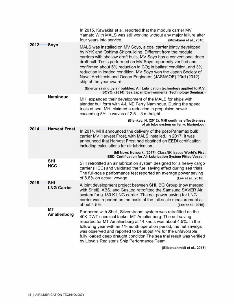
In 2015, Kawakita et al. reported that the module carrier MV Yamato With MALS was still working without any major failure after four years into service. (Mizokami et al., 2010)
2012 Soyo MALS was installed on MV Soyo, a coal carrier jointly developed by NYK and Oshima Shipbuilding. Different from the module carriers with shallow-draft hulls, MV Soyo has a conventional deep-draft hull. Tests performed on MV Soyo reportedly verified and confirmed about 5% reduction in CO2 in ballast condition, and 3% reduction in loaded condition. MV Soyo won the Japan Society of Naval Architects and Ocean Engineers (JASNAOE) 23rd (2012) ship of the year award.
(Energy saving by air bubbles: Air Lubrication technology applied to M.V. SOYO. (2014). Sea Japan Environmental Technology Seminar.)
Naminoue MHI expanded their development of the MALS for ships with slender hull form with A-LINE Ferry Naminoue. During the speed trials at sea, MHI claimed a reduction in propulsion power exceeding 5% in waves of 2.5 – 3 m height.
(Blenkey, N. (2012). MHI confirms effectiveness of air lube system on ferry. MarineLog)
2014 Harvest Frost In 2014, MHI announced the delivery of the post-Panamax bulk carrier MV Harvest Frost, with MALS installed. In 2017, it was announced that Harvest Frost had obtained an EEDI certification including calculations for air lubrication.
(MI News Network. (2017). ClassNK Issues World’s First EEDI Certification for Air Lubrication System Fitted Vessel.)
SHI HCC
SHI retrofitted an air lubrication system designed for a heavy cargo carrier (HCC) and validated the fuel saving effect during sea trials. The full-scale performance test reported an average power saving of 8.8% on actual voyage. (Lee et al., 2016)
2015
SHI LNG Carrier
A joint development project between SHI, BG Group (now merged with Shell), ABS, and GasLog retrofitted the Samsung SAVER Air system for a 180 K LNG carrier. The net power saving for LNG carrier was reported on the basis of the full-scale measurement at about 4.5%. (Lee et al., 2016)
MT Amalienborg
Partnered with Shell, Silverstream system was retrofitted on the 40K DWT chemical tanker MT Amalienborg. The net saving reported for MT Amalienborg at 14 knots was about 4.5%. In the following year with an 11-month operation period, the net savings was observed and reported to be about 4% for the unfavorable fully loaded deep draught condition.The sea trial result was verified by Lloyd’s Register’s Ship Performance Team.
(Silberschmidt et al., 2016)

14 | AIR LUBRICATION TECHNOLOGY
REFERENCES Butterworth, J., Atlar, M., & Shi, W. (2015). Experimental analysis of an air cavity concept applied on a ship hull to improve the hull resistance. Ocean Engineering, 110, 2–10.
Ceccio, S. L. (2012). Air Lubrication Drag Reduction on Great Lakes Ships. Great Lakes Maritime Research Institute, 32.
Domenico, S. N. (1982). Acoustic wave propagation in air-bubble curtains in water—Part I: History and theory. Geophysics, 47(3), 345-353.
Foeth, E. J. (2011). The efficacy of air-bubble lubrication for decreasing friction resistance. The Naval Architect, (APRIL), 44–46.
Harvest Frost. (December 2014). Harvest Frost: Ship floats on bubbles. Maritime Reporter and Engineering News.
Hoang, C. L., Toda, Y., & Sanada, Y. (2009, January). Full scale experiment for frictional resistance reduction using air lubrication method. In The Nineteenth International Offshore and Polar Engineering Conference. International Society of Offshore and Polar Engineers.
IMO MEPC 73/19. (2018). Report of the marine environment protection committee on its seventy-third session.
IMO MEPC.1/Circ.815. (2013). 2013 guidance on treatment of innovative energy efficiency technologies for calculation and verification of the attained EEDI.
Jang, J., Choi, S. H., Ahn, S. M., Kim, B., & Seo, J. S. (2014). Experimental investigation of frictional resistance reduction with air layer on the hull bottom of a ship. International Journal of Naval Architecture and Ocean Engineering, 6(2), 363-379.
Kumagai, I., Takahashi, Y., & Murai, Y. (2015). Power-saving device for air bubble generation using a hydrofoil to reduce ship drag: theory, experiments, and application to ships. Ocean Engineering, 95, 183-194.
Lee, J., Kim, J., Kim, B., Jinho Jang, Mcstay, P., Raptakis, G., & Fitzpatrick, P. (2016). Full Scale Applications of Air Lubrication for Reduction of Ship Frictional Resistance Feasibility of Drag Reduction, 1(V), 1–12.
Peifer, B. C., Callahan-Dudley, C., & Makiharju, S. A. (2018). Air Layer on Superhydrophobic Surface for Frictional Drag Reduction, (August), 5–10.
Perlin, M. & Ceccio, S. (2014). Mitigation of hydrodynamic resistance: Methods to reduce hydrodynamic drag. World Scientific.
Silberschmidt, N., Tasker, D., Pappas, T., & Johannesson, J. (2016). Silverstream ® System – Air Lubrication Performance Verification and Design Development. Shipping in Changing Climates Conference 2016, 1–12.
Sverchkov, A. V. (2010, May). Application of air cavities on high-speed ships in Russia. International Conference on Ship Drag Reduction, Istanbul.

15 | AIR LUBRICATION TECHNOLOGY
CONTACT INFORMATION
NORTH AMERICAN REGION 1701 City Plaza Drive Spring, TX 77389 USA Email: [email protected] SOUTH AMERICAN REGION Rua Sao Bento 29-11 Floor, Centro Rio de Janiero 20090-010 Brazil EUROPE and AFRICA REGION ABS House No.1 Frying Pan Alley London E1 7HR, UK MIDDLE EAST REGION Al Joud Center 1st Floor, Suite #111 Sheihk Zayed Road P.O. Box 24860, Dubai United Arab Emirates GREATER CHINA REGION 5th Floor, Silver Tower No.85 Taoyuan Road Huang Pu District Shanghai, 200021 P.R. China NORTH PACIFIC REGION 11th Floor, Kyobo Life Insurance Building, 7, Chungiang-Daero, Jung-Gu, Busan, 48939, Republic of Korea SOUTH PACIFIC REGION 438 Alexandra Road, # 08-00 Alexandra Point, Singapore 119958 Republic of Singapore © 2019 American Bureau of Shipping All rights reserved