air hoist & trolley user manual model - tcs-980-at2s
TRANSCRIPT

AIR HOIST & TROLLEYUSER MANUAL
MODEL - TCS-980-AT2S


3
USER MANUAL
▪ Red Rooster Lifting Limited ▪ Nauta House, The Meadows, Oldmeldrum, Aberdeenshire, AB51 0EZ ▪ Tel: +44 (0) 1651 872101 ▪
FRONT COVER
CONTENTS
INTRODUCTION & SPECIFICATION
SECTION 1: GETTING STARTED
1.1 UNPACKING & SPECIFICATION 1.2 OPERATION 1.3 CHECKS BEFORE USE & HOSE SUPPORT BRACKET 1.4 INSTALLATION 1.5 TECHNICAL CHARACTERISTICS 1.6 HOIST CHECKS 1.7 HOIST CONTROLS 1.8 ADDITIONAL INSTALLATION INSTRUCTIONS 1.9 INSTALLING THE HOIST & TROLLEY 1.10 ASSEMBLY & INSTALLATION
SECTION 2: LUBRICATION
SECTION 3: SAFE OPERATION 3.1 HOIST OPERATORS & FORESEEABLE INCORRECT USE 3.2 SAFETY EQUIPMENT - PPE 3.3 LIFTING GEAR BELOW THE HOIST 3.4 OPERATIONAL BREAKDOWN OR ACCIDENT SECTION 4: MAINTENANCE
4.1 GENERAL 4.2 REPAIRS 4.3 TROLLEY VANE MOTOR MAINTENANCE 4.4 SILENCING 4.5 CHANGING HOIST SILENCERS 4.6 CHAINGING TROLLEY SILENCERS 4.7 FITTING OR REPLACING LOAD CHAIN 4.8 TYPES OF CHAIN 4.9 EMERGENCY LOWERING 4.10 HOIST COMPONENTS AND CHAIN 4.11 SERVICE DATA
SECTION 5: LAYING UP THE HOIST SECTION 6: CHAIN COLLECTORS SECTION 7: SPEED & LOAD LIMITER ADJUSTMENT SECTION 8: OPERATIONAL BREAKDOWN / TROUBLESHOOTING THE TCR & TCS HOIST
SECTION 9: PERIODIC EXAMINATION & TESTING 9.1 EXAMINATION 9.2 SIX MONTHLY OFFSHORE INSPECTION 9.3 TESTING
SECTION 10: DUTY RATINGS SECTION 11: EXPLOSION PROTECTION
SECTION 12: TECHNICAL SPECIFICATION
SECTION 13: DATA SHEET SECTION 14: DRAWINGS AND PARTS LISTS SECTION 15: ACCESSORIES
SECTION 16: LOG BOOK

4
USER MANUAL
▪ Red Rooster Lifting Limited ▪ Nauta House, The Meadows, Oldmeldrum, Aberdeenshire, AB51 0EZ ▪ Tel: +44 (0) 1651 872101 ▪
INTRODUCTION AND SPECIFICATION
Thank you for choosing the TCS pneumatic chain hoist which are available from 500 kg to 980 kg.
Provided that the hoist is used and maintained in accordance with this manual it will afford you many years of reliable service.
RedRoosterhoistscomplywiththelateststandardsandaredesignedforsafeandefficientoperation.
Before installing the unit, please ensure that both the personnel responsible for installation, maintenance and operation are fully acquainted with the sections of this manual which are relevant to them.
This manual should be accessible at all times to the relevant person, in case of loss ask your dealer for a new copy.
Air pressure - 6 bar Specificationsheetgivesfulldetailsofactualmodelsupplied. Thenameplatefittedtothehoistgivesthedetailstoidentifyandgivesfurtherinformationonthehoist.
Notations: The following notations are used throughout this manual.
Failure to follow this instruction may result in a dangerous occurrence or fatal injury
Failure to follow this instruction may result in premature wear of the hoist or a component part of the hoist
SWL (TONNE)
TROLLEY MODEL
HOISTMODEL
CHAIN FALLS
HOIST & TROLLEY WEIGHT (KG)
AIR FLOW(L/SEC) DRIVEN
WHEELS
MINIMUM HOSE SIZE
(ID)3M HOL EXTRA P/M HOIST TROLLEY
0.5 AT2S TCS-500 1 59 0.8 28 25 2 3/8" / 1/2"
0.98 AT2S TCS-980 1 62 1.6 28 25 2 3/8" / 1/2"
DANGER
CAUTION

5
USER MANUAL
▪ Red Rooster Lifting Limited ▪ Nauta House, The Meadows, Oldmeldrum, Aberdeenshire, AB51 0EZ ▪ Tel: +44 (0) 1651 872101 ▪
GETTING STARTED - UNPACKING & SPECIFICATION
1.1 UNPACKING THE HOIST Thehoistwillhavebeenpackedintoacardboardbox,crateorpalletised(seeweightdetailsinspecification). Handling of all models of hoist & trolley will require lifting equipment and shouldn’t be moved by hand.
WHEN UNPACKING: Ensure that both hoist and any ancillary equipment are recovered from the packaging. Small or delicate items may have been packed separately. Check the contents against the supplier’s delivery note and advise the supplier immediately of any shortages. Ensure that the hoist and ancillary equipment are undamaged. If the goods do not reach you in perfect condition, notify your supplier immediately of any damage. Do not proceed with installation if the goods are damaged.
Ensurethatacertificateoftestandthoroughexaminationtogetherwitha‘CE’certificateofconformityisincludedwiththegoods.Handthese tothe‘responsibleperson’forsafekeeping.Checkthattheidentifyingmark(serialno),thesafeworkingload(liftingcapacity)andthe‘CE’ mark appear on the hoist.
SUPPLIER / MANUFACTURER Red Rooster Lifting Ltd Red Rooster Lifting Ltd ADDRESS Nauta House, The Meadows Unit 26 Kelvin Way Trading Estate Oldmeldrum, Aberdeenshire Kelvin Way, West Bromwich UK, AB51 0EZ West Midlands, U.K. B70 7TW
TEL NO 01651 872101 0121 525 4162
MODEL TCS-980-AT2S SERIAL NO SWL 980 KG DATE OF PURCHASE
NAME PLATES The name plate gives important information which must be retained. Hoist serial number, SWL, model, year of manufacture and the manufacturers name and address.
ATEX - Explosive protection WhenanewhoisthasbeenbuiltwithincreasedsparkprotectionanATEXnameplatewillbefitted. The normal ATEX zone 1 rating for Red Rooster air hoists is Group II 2 GD c IIB T4 (135°C). This is based on European ATEX Directive 2014/34/EU
CERTIFICATION Allnewhoistsaresuppliedwithstandardcertification:ThoroughExamination,EUDeclarationofConformity,whichincludesATEXcertificate where required. Other documentation is available by agreement.
IN THE EVENT OF ANY PROBLEMS OR SHOULD YOU REQUIRE ASSISTANCE CONTACT THE SUPPLIER AS DETAILED ABOVE QUOTING THE HOIST MODEL AND SERIAL NUMBER.
PACKAGING MATERIALS SHOULD BE RECYCLED OR DISPOSED OF ACCORDING TO LOCAL REGULATIONS.
DANGER

6
USER MANUAL
▪ Red Rooster Lifting Limited ▪ Nauta House, The Meadows, Oldmeldrum, Aberdeenshire, AB51 0EZ ▪ Tel: +44 (0) 1651 872101 ▪
GETTING STARTED - OPERATION
1.2 OPERATION Red Rooster pneumatic hoists and trolleys are designed for the lifting, lowering and moving of loads along a runway beam or swing jib within the capacityoftheselectedhoistmodel.Ourrangesofhoistsareall‘CE’markedandconformwiththeMachineryDirective2006/42/ECandthe powered hoist standard BS EN 14492-2
Our range of hoists and trolleys are available as hook suspension units, trolley mounted, built into low headroom units and cranes. Nearly all hoist models are also available as ATEX ZONE 1 or 2 hoists for use in hazardous areas, with corrosion protection, and can work in temperatures of -10°C to +70°Canddownto-20ºCwithsmallmodifications.Ourairtrolleystandardoperatingtemperatureis-10ºCto+50ºCbutwith different valves they can work in -20ºC to +60ºC. When used outdoor or offshore hoists should be protected against the weather and examination and maintenance interval should be reduced.
Our hoistand trolleys are extremely robust being developed over many years in the harshest of environments and will require little maintenance if keptlubricatedonaregularbasis.Noiselevelscanbefoundinthetechnicalspecificationandasmotorlubricatingoilissuppliedthroughthe filterlubricatorfittedtothehoisttherewillbeasmallamountofoilescapingintotheatmospherethroughtheexhaustair:thiscanbepipedaway or collected using an exhaust cleaner. In certain circumstances and temperatures there is a danger of icing of the motor and exhaust silencer. Thiscanbepreventedbyusingananti-icinglubricantsuchasSilkairorbyfittingadryertotheairsupplytoremovemoisturefromtheair supply. Some anti-icing oil may damage air hoses and the o-ring in the hoist valve.
2
6
5
1
10
9
11
12
48
3
7
13
Images for illustration purposes only
1 Trolleywheelswithsealedbearings(tosuitflatortaperedbeams)
2 Anti-tiltrollers(canbesettosuitflange)
3 Gear box
4 Air motor
5 Control valve
6 Silencers ( low noise levels)
7 Load bar (wide range to suit beam)
8 Lock nuts
9 Split pin
10 Adjusting spacers / washers (for easy adjustment)
11 Buffers (standard on ATEX units)
12 Link plate (to suit all Red Rooster hoists)
13 Lift points in side plates for shackles
CAUTIONCAUTION

7
USER MANUAL
▪ Red Rooster Lifting Limited ▪ Nauta House, The Meadows, Oldmeldrum, Aberdeenshire, AB51 0EZ ▪ Tel: +44 (0) 1651 872101 ▪
GETTING STARTED - CHECKS BEFORE USE & HOSE SUPPORT BRACKET
1.3 CHECKS BEFORE USE These checks should be carried out during installation and on a frequent and regular basis thereafter. If the hoist is used daily then it is recommendedthattheyarecarriedoutdailyasthecheckstakeonlyminutestocompleteandnotonlyhelpavoidrepairbillsbutsignificantly reduce the possibility of an accident or dangerous occurrence. Thoroughly examine the equipment prior to installation to ensure that no damage has occurred during transit. Hoists and trolleys should not be altered in any way without contacting Red Rooster for clearance, as this mayaffectthecertificationoftheunit.
AIR SUPPLY CHECKS: ▪ Inletpressure:4to6bar(therewillbepressurelossesacrosstheairsetandonlonghoses)Thesupplypressureshouldnot exceed 7 bar as this may affect the load limiter. ▪ Airflow:Checkairflowrequirementandminimumhosediameteralsocheckthatsmallborefittingsarenotstranglingtheairflow. ▪ Keepthelubricatortoppedupwithalightturbineoil(ISOVG3256). ▪ Thefiltershouldbecheckedregularlyandmanualunitsdrainedofwaterasrequired. ▪ THE AIR HOSE SHOULD BE SUPPORTED SO THAT THE WEIGHT OF HOSE IS NOT HANGING FROM THE AIR SET AND FITTINGS. THE AIR SET IS NOT DESIGNED TO SUPPORT THE WEIGHT OF THE HOSE. SEE PAGES 7 AND 12 IF A HOSE SUPPORT BRACKET AND MANIFOLD IS FITTED TO THE HOIST. ▪ Theairsupplyshouldbecleanandrelativelydry.Wherethecompressorproducesalotofwateractionshouldbetakentoremove the excess water. ▪ Checkairconnectionsizeandtypearecompatible. ▪ Checksecurityofairhoseconnection.
AIR SUPPLY CONNECTION: Every installation is different, so the correct method of supporting the air hose should be reviewed while installing the hoist. This needs to take into account the weight and size of the hose, obstructions both at deck and hoist level, connections, operating conditions and any likely movement of the hoist and air hose. Thefittingsandfilterlubricatorarenotdesignedtotaketheweightofthehose. If the air supply hose length is over 10 metres the hose ID should be increased to the next size.
AIR SUPPLY: Vanetypeairmotorsaredesignedtofunctionusingclean,dry,lubricatedair.Theinstallationofan‘inline’airserviceunitalthoughessential cannot in itself compensate for serious contamination in the air supply. When operating the compressor in moist (humid) or dusty atmospheres seektheadviceofyourcompressorsupplierwithregardtothefittingofadryerandfilter.
AIR PRESSURE: The hoist is designed to operate best in the pressure range of 5 to 6 bar (72 to 90 p.s.i). The speeds quoted on the manufacturer’s literature areobtainableonlyat6bar(90p.s.i)inletpressure.Thehoistwilloperateatmuchreducedspeedatpressuresbelowthisfigure.
AIR FLOW:
Refertothehoistdatasheet,toselectthehosediameterwhichensuresadequateairflow.Failuretoprovideadequateairflowwillresultina pressure drop in the supply line and cause the hoist to stall and the brake to apply until the pressure increases. In addition, the brake will not release cleanly and will overheat. (Although not in itself a hazard [the brake will fail safe] it may prove frustrating to the operator and a hazard may arise as a consequence.)
HOSE SUPPORT BRACKET: Whereahosesupportbracketandmanifoldhavebeenfittedtothehoisttotaketheweightofanairsupplyhose,severalchecksmustbedone.
▪ Checkthehosehangsfreelyanddoesnotinterferewiththehoistchain. ▪ Checkthehoseisclearoftheloadtobelifted. ▪ Checkthependanthoseisnotobstructedbytheairsupplyhose. ▪ Checktheairhoseissupportedbythehoseclamp/former/festoonsystem.
▪ DOuseexclusivelycorrectlyratedpneumatichosesandfittingsintheairsupplyline. ▪ DOsupporttheairlineuptothehoist,asthefittingandfilter/lubricatorarenotdesignedtotakealoadandmaynotsupportthe weight of the hose. ▪ DOmaintaintheinternaldiameter(asperthetablethroughoutthesupplylength)orreducefromthelargerdiametertothe smaller diameter in the direction of the hoist. ▪ DON’Tusehydraulicfittings.Theseoftenhaveareducedorificesizeresultinginadownlinedropinairpressure. ▪ DON’Tincreasefromsmallertolargerdiameterorinsertalengthofsmallerdiameterhoseinthesupplylineasthiswillresultin reducedflowandpressure. ▪ DON’Tcreatelowpointsintheairsupplylinewherewatermaybetrapped(orifunavoidableinstalladraintap). ▪ DON’Trelyonpneumaticfittingstosupportairlines;theyarenotdesignedforthispurpose. ▪ DON’Tshortenthependantbyformingalooporacoil.Thiswillpreventthestrainerwirefromsupportingthependantandwill cause the hoses to become detached or kinked.
CAUTIONCAUTION
CAUTIONCAUTION
DANGER

8
USER MANUAL
▪ Red Rooster Lifting Limited ▪ Nauta House, The Meadows, Oldmeldrum, Aberdeenshire, AB51 0EZ ▪ Tel: +44 (0) 1651 872101 ▪
GETTING STARTED - INSTALLATION & TECHNICAL CHARACTERISTICS
1.4 HOIST ASSEMBLY
Normallyourhoistorhoistandtrolleyswillarrivecompletereadytobefittedintoposition,butsometimesfortransportationitmaybe necessary to disconnect the chain collector, trolley or the pendant control system. ▪ Chaincollectorswillbesuppliedwiththenecessaryboltsandfittingstoassembleonsitealongwithanysafetyslingsasshownin section 1.8 and chain collectors in section 7.4. ▪ Duetothesizeofsometrolleysitiseasiertoshipsplitfromthehoist,thetrolleyGAdrawingsshowtheloadbarandtopeyedetails forrefittingandthecontrolandsupplyairlinesarenumberedorcolourcodedforre-connection. ▪ Whenliftingintopositioneitherusetheliftingpointsonthehoistorhoistandtrolley,ifthehoistdoesnothaveliftingpointsfitted securely fit slings to the body of the hoist or use the top hook if possible. Do not lift by the controls, valves, or the air set.
MOUNTING THE HOIST
The air hoist is designed as a LIFTING MACHINE and as such is designed exclusively for the lifting loads vertically. Non vertical lifting will result in premature wear of the chain and chain guide and may result in damage to the limit arms or a failure of the limit arms to operate. Thetrolleyisdesignedtomoveloadsalongarunwaybeamorswingjib.Itmustbecorrectlyadjustedfortheflangewidthandthickness.
▪ Sitethehoistimmediatelyabovetheloadwhichistobelifted. ▪ Ensurethatthepointfromwhichthehoistissuspendedhasbeendesignedandtestedtoatleastthesamesafeworkingloadas the hoist itself. ▪ Ensurethatthesuspensionpointorshacklefitssnuglyintothebowlofthehoisttophookandthatthesafetycatchclosesto prevent escape. ▪ UseonlycertifiedliftinggearwithaSWLinexcessoftheloadtobeliftedtoconnecttotheloaditself. ▪ Ensurethattheliftinggearfitssnuglyintothebowlofthehoistbottomhookandthatthesafetycatchclosestopreventescape. ▪ Ensurethatthecontrollength(pendantorcords)isadequatetoallowtheoperatortostandawayfromtheload,inasafeand secure position with the cords or pendant at waist height.
TROLLEY ASSEMBLY
▪ Thoroughlyexaminetheequipmentpriortoinstallationtoensurethatnodamagehasoccurredduringtransit,. ▪ Checkthewheelprofilematchesthebeam. ▪ Neveruseadamagedtrolley. ▪ MatchthetrolleytotheSWLofthebeamandthetypeofhoisttobefitted. ▪ Checktheloadbarnutsaretightandthelinkplateinthecentreoftheloadbar. ▪ Trolleysshouldbecleanedinadrycleanarea. ▪ Donotsideloadthetrolley.
TROLLEY CHECKS The contents of this section are designed for the guidance of personnel using push or geared trolleys. ▪ Ensurethatthetrolleyissettothecorrectsizeforthebeam. ▪ Ensuretherunwayisfittedwithadequateendstops. ▪ Ensuretherunwayloadpathisclearofobstructions. ▪ Ensurethatthetrolleytiebarsarecorrectlysecured.
DANGER

9
USER MANUAL
▪ Red Rooster Lifting Limited ▪ Nauta House, The Meadows, Oldmeldrum, Aberdeenshire, AB51 0EZ ▪ Tel: +44 (0) 1651 872101 ▪
GETTING STARTED - INSTALLATION & TECHNICAL CHARACTERISTICS
1.4 CLOSE HEADROOM WORKING
The lower hook of the TCR / TNC / TCS / TMH hoist includes a swivel arrangement. This allows the load to turn without twisting the chain. However, when repeatedly handling loads with the bottom hook close to the hoist, especially when rotation of the load is prevented, there is tendency for the chain to attempt to enter the guide at an angle. This is particularly pronounced on two fall units. If this problem is noticed when doing a trial lift, a high quality ball bearing swivel should be mounted below the bottom hook of the hoist.
CHAIN COLLECTORS
If the hoist has been supplied with a chain collector bag or bucket, and the chain has been stored within it during shipment, remove all the chain from the collector by hand, and remove any knots or twists. Inallcasescarefullyfeedthechainovertheloadwheelallowingittofillthecollectorwithoutanyinterferenceasitemergesfromthewheel. Thiswaythecollectorwillfillnormally.Ifthechainwithinthecollectorisdisturbedgreatcaremustbetakenthenexttimethatthechainisfed outofthecollectortoensurethatitisnottwistedorknotted.Chainbagsandbucketsarefittedwithoneortwobracketsdependingonthe model and HOL of the hoist. See additional instructions (Section 6) for large collectors.
1.5 TECHNICAL CHARACTERISTICS TheWLLofthehoistandtrolleywillbemarkedonthehoist/trolleynameplateandalsointhehoistspecificationsupplied. The reactions on the powered hoist on the support, runway beam or crane should have been taken into account in the design of the structure. The structure should be at least 25% stronger than when using manual equipment due to the shock loading applied by the operational speeds and the starting and stopping of the hoist.
AllRedRoosterhoistsarefittedwiththefollowingsafetyfeatures
▪ Overloadlimiter ▪ Upperandlowermechanicallyoperatedtravellimits.Theseareultimatestopsandshouldnotbeusedtostopthehoistonaregular basis. ▪ Thediscbrakeisspringappliedsowhenthecontrolsarenotoperatedorintheeventoflossofairsupplythebrakeisapplied holding the load in position. ▪ Onpendantcontrolledhoistsanemergencystopbuttonisfittedwhichconnectstoanormallyopenvalveeitherlocatedinthehoist valve chamber or connected to the hoist. When the emergency stop button is pushed or if the air supply to the hoist is cut off then the valve will close stopping the hoist. ▪ RedRoosterhoistshavea5:1factorofsafety.
DANGER

10
USER MANUAL
▪ Red Rooster Lifting Limited ▪ Nauta House, The Meadows, Oldmeldrum, Aberdeenshire, AB51 0EZ ▪ Tel: +44 (0) 1651 872101 ▪
GETTING STARTED - HOIST CHECKS
1.6 HOIST CHECKS BEFORE USE
HOIST CHECKS (AIR SUPPLY OFF)
▪ Hookswivelssatisfactorilyandthesafetycatchesworkcorrectly. ▪ Loadchainisundamagedandlubricated(lightmineraloil). ▪ Theloadchainisnottwistedthrough(twofallormoremodels)andthattheloadchainpassedthroughthelimitlever(Allmodels). ▪ Theloadchainanchorissound(bothliveandslackend). ▪ Checkfordamagetothehoist,pendantandcontrollines. ▪ Donotoperatedbelow-10°C or above 70°C without contacting Red Rooster. (The hoist can be used down to -20ºC with small modifications)
HOIST CHECKS (AIR SUPPLY ON)
▪ Thependantbuttons,leversorcordsshouldbesmoothtooperateandreturntoneutralwhenreleased(hoiststopsanddoesnot run on). ▪ Thehoistisrunupanddownonaregularbasis.Wherehoistsarehanginginadryandprotectedareatheyshouldberunweekly, where the hoist is outside and not protected it should be checked, lubricated and run daily. ▪ Theemergencystopbutton/valveoperatesimmediately. ▪ Upperandlowerlimitswitches/leversworksatisfactorily. ▪ Loadchainsrunsmoothlyoverthepocketwheel. ▪ Theloadchainshouldbeexaminedperiodicallyforcracks,gougesandwear. ▪ Chaincollectorsshouldbecheckedforsecurityandchaincapacity. ▪ Checkchainrunsinandoutofthechaincollectorsmoothly. ▪ Forhoistswithalongdropofchainoralargechaincollectoraseparatesuspensionpointmayberequired(seesection1.8). ▪ Cordcontrolhoistsshouldhavethetogglesmarkedforraiseandlower. ▪ Oncordcontrolscheckthespoolvalvereturnstoneutralandthehoiststopswhenthecordisreleased.(hoiststopsanddoesnot run on). ▪ Checkthesilencerisnotpartiallyblockedbycomparingtherunningspeedwithoutloadagainstthespeedinthemanual.
NEVER RELEASE THE EMERGENCY STOP BUTTON UNTIL IT IS SAFE TO DO SO
Hoist swivels satisfactorily. Hoist safety claws functional and undamaged.
Safety claw
Chain undamaged Chain not twisted through (two fall models see sketch)
twisted
DANGER
DANGER
correct
DANGER

11
USER MANUAL
▪ Red Rooster Lifting Limited ▪ Nauta House, The Meadows, Oldmeldrum, Aberdeenshire, AB51 0EZ ▪ Tel: +44 (0) 1651 872101 ▪
GETTING STARTED - HOIST CHECKS & INSTALLATION INSTRUCTIONS
1.7 HOIST CONTROLS Air hoists can be controlled by either a pull cord or a pendant control operating the spool valve of the hoist operating raise and lower. The diagram at the bottom of this page shows the set up for both types of control and the location on the hoist body.
Cord or pendant hose lengths should be long enough for the operator to stand away from under the load but still with the cord toggles or the pendant suspended at a height of around 1 metre from the operating level. Where the controls have to be to the side of the hoist or where the operator cannot see the load travelling the full range of the lift a banksman should be appointed to assist the operator using a reliable means of communication.
1.8 ADDITIONAL INSTALLATION INSTRUCTIONS Hook suspension with long chain drops.
Problem: Whenalongheavychainisfitted,andthe‘raise’ispressedwiththehoistinanunloadedcondition,duetothecentrelineofthehoisthaving been affected by the weight of chain, the upper limit switch, may fail to operate. In addition, the slack load chain may on some modules foul the limit lever arms, thus preventing it from returning to the centre (neutral position).
Resolution: Ashortlengthofwirerope,6mmdiameter,isfittedtothehoistsandbulldoggripshavebeensupplied. Suspendthehoistinitsfinallocationandwithasmuchchainaspossibleinuse.Applyasmallloadtothehoistandliftitclearoftheground. Connect the wire rope sling to the support steel alongside the top hook using bulldog grips. The tension in this sling should be enough to counteract most of the weight of the slack chain produced in the fully raised position, but it must notbetensionedsuchthatitiscarryinganyoftheloadsupportedbythehoist.i.e.iffittedcorrectly,inanunloadedcondition,theslingwillbe tensioned with the hoist ALMOST in the vertical position. When the load is applied, the tension in the sling will be slack. Trolley Resolution: Whenahoistandtrolleyarefittedwithheavychainoralongdrop,asecondpushtrolleycanbeusedinthesamewaytosupporttheweight.
THE SLING IS NOT CAPABLE OF HOLDING THE LOADS CARRIED BY THE HOIST

12
USER MANUAL
▪ Red Rooster Lifting Limited ▪ Nauta House, The Meadows, Oldmeldrum, Aberdeenshire, AB51 0EZ ▪ Tel: +44 (0) 1651 872101 ▪
GETTING STARTED
STAN
DA
RD
HO
SE CO
NN
ECTIO
NPEN
DA
NT C
ON
TRO
L OR
H
OIST W
ITH EXTER
NA
L EM
ERG
ENC
Y STOP VA
LVE
STAN
DA
RD
HO
SE CO
NN
ECTIO
NC
OR
D C
ON
TRO
L OR
H
OIST W
ITH IN
TERN
AL
EMER
GEN
CY STO
P VALVE

13
USER MANUAL
▪ Red Rooster Lifting Limited ▪ Nauta House, The Meadows, Oldmeldrum, Aberdeenshire, AB51 0EZ ▪ Tel: +44 (0) 1651 872101 ▪
GETTING STARTED
**Som
ehoistsarefittedwithinternalem
ergencystopvalves**Thehoseclam
pcanalsobefittedtothetrolleysideplate.

14
USER MANUAL
▪ Red Rooster Lifting Limited ▪ Nauta House, The Meadows, Oldmeldrum, Aberdeenshire, AB51 0EZ ▪ Tel: +44 (0) 1651 872101 ▪
GETTING STARTED - INSTALLING THE HOIST & TROLLEY
1.9 RRI trolleys can be plain (non-powered), hand chain (geared) or powered (pneumatic) Hoists can be hook-mounted to the suspension shaft of the trolley, or rigidly mounted to a trolley hanger bracket.
This trolley has been designed for horizontally transporting loads by hand, through manual or pneumatic hoists under normal atmospheric conditions of the work place.
In order to ensure the maximum performance and life from this pnuematic trolley it is essential that the following points are strictly observed.
▪ Thetrolleyairmotormaybeoperatedinanyattitudeprovidedadequatelubricationissupplied. Being totally enclosed they can be used in any environment within the temperature limits of -10ºC to +50ºC. (optional parts -20ºC to +60ºC) ▪ Themaximumworkingpressurefortheairmotoris7bar(100psi) ▪ Besuretoadjusttheanti-tilttollerstothehighestpositionpossibleintheslottoleavetheminimumclearancebetweentheunderside of the beam and the top of the roller. ▪ Axialloadsshouldbekepttoaminimum. ▪ Careshouldbetakenwhenfittingdrivecomponentstotheshaft,thatexcessiveforceisnot used. This will upset the rotor alignment which has been kept to a minimum in order to give high motor performance. ▪ Checkthedrivepinion/gearedwheelsaregreased. OPERATION
Plain Trolley The trolley movement is controlled by pushing the load or the hook of the attached hoist. Geared Trolley Face the hand wheel side of the trolley. To move left, pull hand chain clockwise. To move right, pull hand chain counterclockwise,
Pneumatic Trolley The trolley directionis controlled by the pendant buttons or levers. Face the trolley motor side plate and use the white or black arrows to control the pendant. The emergency stop buttons stops the trolley.
Trolleys are either delivered assembled for the beam size advised, or assembling but require to be adjusted to the correct beam size.
The lifting points at the top of the trolley above the gearbox should be used for lifting the hoist and trolley into place. Care must be taken not to allow the unit to swing, as the gearbox flange can be damaged and broken if it is allowed to impact against steelwork etc. If contact is made, the flange should be inspected and removed from service for repair.
MOUNTING
Make certain the hoist is properly installed. A little extra time and effort in doing so can contribute a lot toward preventing accidents or injuries and will help achieve the best service possible.
When installing a trolley on a beam, measure the beam flange width and temporarily install the trolley to determine the exact distribution and arrangement of the spacers.
HOOK MOUNTED HOIST
After final trolley installation place hook over suspension shaft or eye. Make sure hook latch is engaged.
If the hoist is suspended by a top hook, the trolley suspension shaft should rest completely within the saddle of the hook and be centred directly between the side plates.
RIGID / EYE MOUNTED HOIST
Mount hoist to trolley and temporarily install on beam to determine exact distribution of spacers to centre the top eye.
After installation, operate trolley over entire length of beam with a capacity load suspended 10 to 15cm off the floor.

15
USER MANUAL
▪ Red Rooster Lifting Limited ▪ Nauta House, The Meadows, Oldmeldrum, Aberdeenshire, AB51 0EZ ▪ Tel: +44 (0) 1651 872101 ▪
GETTING STARTED - INSTALLING THE HOIST & TROLLEY
1.9 FITTING TROLLEYS IN LOCATION
MOUNTING FROM THE RAIL END
Air trolleys can either be fitted to the runway beam or swing jib in two ways.
1) By removing the end stop from the beam and sliding the trolley which is already set for the flange size on to the beam and then re-fitting the end stop.
MOUNTING BY DISASSEMBLING THE MAIN TROLLEY BODY
2) By opening the trolley up so that the inner part of the wheels will pass over the beam flange and then sliding the trolley side plates back along the shaft, refitting the spacers, washers and nuts and then tighten up the nuts and check the wheel setting. Be sure to firmly support the parts during reassembly from the bottom side so that the sideplates are not twisted or otherwise shifted. On completion of reassembly, be sure to confirm that various shafts, nuts, lock pins and split pins are properly fastened without any slack and have not been loosened.
END STOP
PLAIN SIDE PLATE ASSEMBLY
MOTOR SIDE PLATE ASSEMBLY

16
USER MANUAL
▪ Red Rooster Lifting Limited ▪ Nauta House, The Meadows, Oldmeldrum, Aberdeenshire, AB51 0EZ ▪ Tel: +44 (0) 1651 872101 ▪
GETTING STARTED - INSTALLING THE HOIST & TROLLEY
1.9
SETTING THE TROLLEY (up to 3 tonne)
1) Slide the hook receiving part or link plate near the suspended shaft centre and grease the shaft. 2) Distribute the spacer rings and adjusting collars equally to either side of the link plate, in order to obtain the dimensions between the wheels, corresponding to the beam width plus 2 or 3mm. 3) Distribute on each side of the side plates, washers and adjusting collars that are remaining and screw a nut on each extremity. 4) Tighten the nuts and lock nuts on the load bar and check the clearance between the beam flange and the wheel flange. 5) Position the tie-rods, anti-tilt rollers, washers and nuts into the slots in each of the side plates. Set to give the minimum amount of clearance betweeen the underside of the beam and the top of the anti-tilt roller. Then tighten the nut against the roller and side plate and re-check the wheel setting.
PLAIN SIDE-PLATE
MOTORSIDE-PLATE
WHEELS
ANTI-TILT ROLLERS
TIE BAR
LOAD BAR
SPACER WASHERS
SPACERS
BUFFERS

17
USER MANUAL
▪ Red Rooster Lifting Limited ▪ Nauta House, The Meadows, Oldmeldrum, Aberdeenshire, AB51 0EZ ▪ Tel: +44 (0) 1651 872101 ▪
GETTING STARTED - INSTALLING THE HOIST & TROLLEY
1.9
TROLLEY CHECKS
▪ Ensuretherunwaybeamisfittedwithadequateendstopswhichstrikethebuffer/anti-dropplateonthetrolley. ▪ Ensuretherunwayloadpathisclearofobstructions,flatandingoodcondition. ▪ Ensuretheteethfromthepinionfitcorrectlyintotherackonthebeam(iffitted) ▪ Theairsupplyhoseshouldnotbesuspendedfromthehoistwithoutsupport.Wherefeasible,atautwireorafestoon system should be fitted to allow the hose to run along the bea, without loading the air set or fittings. ▪ Thehoistconnectionplateshouldbeinthecentreoftheloadbarwithanequalamountofspacerseachside. ▪ Whenatrolleyhasbeenopened/splitforadjustingorfitting,theloadbarandtiebarnutshouldberetightened. ▪ Thetrolleysideplatesshouldbeparalleltothebeamflangewhenthenutsaretight. ▪ Donotusethebeamendstopstostopthetrolleyonaregularbasis.Itisasafetymeasure.
DO use exclusively correctly rated pneumatic hoses and fittings in the air supply line. DO maintain the internal diameter (as per the table throughout the supply length) or reduce from the larger diameter to the smaller diameter in the direction of the hoist. DO support the airline up to the hoist, as the fittings and filter/lubricator are not designed to take a load and may not support the weight of the hose. DON'T use hydraulic fittings as these tend to have a reduced orifice size resulting in a down line drop in air pressure. DON'T increase from smaller to larger diameter or insert a length of smaller diameter hose in the supply line as this will result in reduced flow and pressure. DON'T create low points in the air supply line where water may be trapped (or if unavoidable install a drain tap) DON'T shorten the pendant by forming a loop or coil. This will prevent the strainer wire from supporting the pendant and will cause the hoses to become detached or kinked. DON'T allow the air hose to hang from the air set. Neither the air set or fittings are designed to take the weight of the hose.
OPERATION - LOW HEADROOM & ULTRA LOW HEADROOM TROLLEY
1.9 ▪ TheLHRandULHRtrolleyshouldonlybeusedonstraightrunwaybeams.Specialunitsareavailableforcurvedbeamsdesignedto suit the radius. ▪ LHRandULHRtrolleysareusuallydesignedforasetbeamsizebutcanbemadeadjustableifrequired. ▪ LHRandULHRunitsareavailableasstandardorATEXversionsandwithourin-housedesignteamspecialunitscanbemanufactured to suit your requirements. ▪ LHRunitsarealsoavailableasarticulatedunitsorwithrackandpiniondriveorbeambrake.
DANGER CAUTION
DANGER
A
A
Title of project Material Weight
Checked by
Designed by
Approved by
Scale Title of part Part number
Revision number
Replaces draw
Surn
ame
Dat
e
Sign
atur
e
2TE Low Headroom 02/12/2014 - 38kgDate
-
0
1:2,5 Trolley DRG 1525-01
T. Mikolajewski
S. Przygoda
B. Aitken
red rooster Red Rooster Industrial (UK) Ltd,
Nauta House, The Meadows,Oldmeldrum, Aberdeenshire, AB51 0EZ
Tel: +44(0)1651 872101Main Fax: +44(0)1651 872098Sales Fax: +44(0)1651 871405
www.rriuk.com
sheet 1/2
25262728
24
20
21
2232
31
30
29
30
31
38 7
4
5
6
520
570
24026
0
3334 40 41
39
43
38
44
42

18
USER MANUAL
▪ Red Rooster Lifting Limited ▪ Nauta House, The Meadows, Oldmeldrum, Aberdeenshire, AB51 0EZ ▪ Tel: +44 (0) 1651 872101 ▪
ASSEMBLY AND INSTALLATION - RACK & PINION TROLLEY
1.10 ▪ Thefittingofarackandpiniontrolleysisverysimilartoastandardairtrolleywiththeadditionofthepinion adjustment to mesh with the rack on the runway beam or swing jib. ▪ Thefourboltsonthedrivenandnon-drivenadjustingplatesshouldbeslackenedtoallowtheplatestodrop down to the maximum rack clearance. ▪ Fitthetrolleyontothebeamasperthestandardinstructions. ▪ Pushtheadjustingplatesupsothatthepinionmesheswiththerackonthebeam,thelowerdownby1to1.5mm. ▪ Slightlytightenthefourboltsonbothadjustingplates. ▪ Checkthepinionshaftisparallelwiththebeamflangeandadjustifnecessary. ▪ Tightenuptheeightbolts ▪ Checktheclearancehasnotchangedbetweenthepinionandtherack. ▪ Functiontestwithaload. ▪ Re-checkthesecurityofallnutsandboltsonthetrolley.
ASSEMBLY AND INSTALLATION - BEAM BRAKE TROLLEY
(See standard trolley installation instructions)
Air and geared trolleys fitted fitted with a beam brakes are manufactured to fit only the size of beam flange they are designed for. If they have to be moved to another beam then a new beam brake shaft would be required. Trolleys can either be air powered or gear travel and are based on a standard trolley fitted with blocks or pads to lock the trolley in location when the chain wheel is turned. The chain is then turned the other way to release the trolley.
Fitting of a trolley with a beam brake should be done from the end of the beam with the end stops removed for fitting. It can be difficult to open up the trolley to fit over the beam and then close up again while suspended. Check operation of beam brake when locked in position. Close beam brake and then try pulling the geared drive chain checking that the trolley does not move.
Title of project Material Weight
Checked by
Designed by
Approved by
Scale Title of part Part number
Revision number
Replaces draw
Surn
ame
Dat
e
Sign
atur
e
1TE Rack & Pinion Hoist 26/02/2014 - 40kgDate
-
0
1:2,5 Trolley (HEB 200 / 3.0 modeule) DRG 1518-28 no dim.
T. Mikolajewski
S. Przygoda
B. Aitken
red rooster Red Rooster Industrial (UK) Ltd,
Nauta House, The Meadows,Oldmeldrum, Aberdeenshire, AB51 0EZ
Tel: +44(0)1651 872101Main Fax: +44(0)1651 872098Sales Fax: +44(0)1651 871405
www.rriuk.com
sheet 1/2

19
USER MANUAL
▪ Red Rooster Lifting Limited ▪ Nauta House, The Meadows, Oldmeldrum, Aberdeenshire, AB51 0EZ ▪ Tel: +44 (0) 1651 872101 ▪
ASSEMBLY AND INSTALLATION - LHR, ULHR & ARTICULATED TROLLEY
1.10 ▪ Thefittingofanarticulatedtrolleywilldependonthedesignofthepowertransferbetweenthetrolleydrivewheels.Thiscaneitherbe with a motor gearbox at one side with a transfer shaft across to the geared wheel on the plain side plate or the trolley can have a motor gearbox on both side plates to drive the trolley. ▪ Thefittingofthetrolleyontothebeamcaneitherbefromtheendofthebeamorthetrolleycanbeopeneduptofitoverthebeam flange.
MOUNTING FROM THE END OF THE RUNWAY BEAM
▪ Checkthetrolleywheelsettingagainsttherunwaybeamflangesize(thesettingshouldbeasperthestandardtrolleysetting) ▪ Removetherunwaybeamendstopandslidetheassembledtrolleyontotherunwaybeampastthepositionfortheendstopandthen re-fit the end stop ▪ Checkthewheelsettingandconnecttheairsupplythenfunctioncheckthetrolleywithoutloadalongthestraightandcurvedsectionsof the runway beam. ▪ IfthetrolleyrunsalongtheworkingareawithoutproblemlifttheSWLforthehoistandtrolleyandtravelalongtherunwaybeam checking for any problems travelling around the curves and over joints.
MOUNTING BY DISMANTLING THE MAIN TROLLEY BODY (TRANSFER SHAFT) - CAUTION
▪ Ifthetrolleyisfittedwithatransfershaftandtheloadbarsaremadeforasetsize,severalpartssuchasthetransfershaft,gears, and bolts will have to be removed at ground level when opening the trolley and then refitted when the trolley side plates are positioned at either side of the runway beam. ▪ Positiononeortwohoistsateithersideoftherunwaybeam,connectthebottomhookstheliftingpointsonthetrolleysideplatesandlift the trolley side plates up to a position where the trolley wheels are level with the beam flange. ▪ Whileholdingthetransfershaftandloadbarsinpositionclosetheplainsideplateontothebeamliningupthetransfershaftgearsand load bars. Check the security of the shafts, load bars and tie bars. ▪ Carryoutchecksandfunctiontestsasperitem1
MOUNTING BY DISMANTLING THE MAIN TROLLEY BODY (DUAL MOTORS)
▪ Wheredualairmotoraremountedontwotrolleysideplatesthisallowsforthetrolleystobeeasilyopenedupatgroundlevel,liftedup and then closed on to the beam flange. ▪ Checktrolleyflangesettingmatchestherunwaybeamflange ▪ Positionthehoistandtrolleyunderthebeamwherethehoistsistobeinstalled ▪ Positiontwoorfourhoistsabovetherunwaybeamandconnectthebottomhookstotheliftingpointsonthetrolleysideplates. ▪ Slackentheloadbarandtiebarnutssothatthesideplatescanslideapart,thenchecktheopeningbetweentheinsideofwheelsis wide enough to go past the beam flange. ▪ Keepingthetrolleylevelliftthetrolleywheelsuptothelevelofthebeamflange. ▪ Nextpushthetrolleysideplatestogether,thentightenthenutsontheloadbarandtiebars,checkallpartsaresecure. ▪ Checkthetrolleywheelsettingonthebeam(asperstandardtrolley)andthenconnecttheairsupplyandfunctiontestthetrolleywithout load along the full length of the curved and straight sections of the runway beam. ▪ NextwiththeSWLofthehoistandtrolleyrunthetrolleyalongtherunwaybeamcheckingmovementaroundanycurvedsectionsand over joints.
Title of project Material Weight
Checked by
Designed by
Approved by
Scale Title of part Part number
Revision number
Replaces draw
Surn
ame
Dat
e
Sign
atur
e
Articulated beam trolley SWL 6T 2011-04-26 - 202kgDate
-
0
1:5 Assembly DRG 1473-00
T. Mikolajewski
S. Przygoda
B. Aitken
red rooster Red Rooster Industrial (UK) Ltd,
Nauta House, The Meadows,Oldmeldrum, Aberdeenshire, AB51 0EZ
Tel: +44(0)1651 872101Main Fax: +44(0)1651 872098Sales Fax: +44(0)1651 871405
www.rriuk.com

20
USER MANUAL
▪ Red Rooster Lifting Limited ▪ Nauta House, The Meadows, Oldmeldrum, Aberdeenshire, AB51 0EZ ▪ Tel: +44 (0) 1651 872101 ▪
LUBRICATION
2.1
Note 1 In all cases oil will be expelled from the hoist and trolley exhaust. The amount discharged is proportional to the delivery rate of the lubricator. In environments where oil in the exhaust cannot be tolerated, the exhaust can be piped away to a safe area, but this requires specialist modificationofthehoist(Seeairserviceequipment)-CONSULTYOURDEALER.
Note 2 All Red Rooster hoist chain must be lubricated to prevent wear. Keeping load chain clean and lubricated will greatly increase the lifetime of the chain and prevent costly replacement. Very little lubricant is needed and can be easily applied to the chain by cloth, brush or spray.
Note 3 Geared wheels (air + geared trolley only) - Lubricate exposed trollley drive pinion and wheel teeth. Brush with grease as often as necessary to keep teeth liberally covered. If the grease becomes contaminated with sand, dirt or other worn materials, remove old greases and replace with new grease (standard grease) during monthly or annual inspection. Temperature range of standard grease is -10ºC to +50ºC. If the trolley is used at temperature below -10ºC or above +50ºC, consult Red Rooster since come parts shall be changed.
Note 4 Trolley wheel bearings do not need to be lubricated and must be replaced if worn or damaged. Hand chain, used on geared trolleys, does not normally require lubrication.
In areas of high corrosion, plated chain can be used along with special lubricants to prevent corrosion from sea water and spray. Chains used in these areas should be re-lubricated on a regular basis.
NEVER use heavy grease or bitumen based products to lubricate the chain as these will foul the chain guide, idler and load wheels and bearings.
RemovedustandwaterdropsontheLoadChainandthenapplylubricant.ApplicationoflubricationinfluencesonthelifeoftheLoad Chainconsiderably.Applythelubricantsufficiently.
AIR SUPPLY FILTER, REGULATOR AND LUBRICATOR LOAD CHAIN LUBRICATION
Item Oil Type Frequency
Lubricator UnitMain Air Supply
AtlubMedium to light turbine oilISO VG 32-56Or any quality airline lubricant(See note 1)
10 to 15 drops per minuteDo not allow lubricator to run out of oil
Load Chain Normal industrial - any light mineral oilClean areas - wax based, semi settingFood industry - suitable vegetable oil(See note 2)
Weekly / monthly subject to environment / use
Limit Lever Linkages and Anchor pins
No. 2 grease Monthly or more frequently in aggressive environments
Gearbox (Hoist) High temperature EP2 grease Only at major overhaul
Gearbox (Trolley) Grade VG220 Only at major overhaul
Trolley Drive Pinion No. 2 Grease Monthly or more frequently in aggressive environments
DANGER
CAUTIONCAUTION
DANGER
Applied Position
Load
Filter Regulator Lubricator
Air In Air Out

21
USER MANUAL
▪ Red Rooster Lifting Limited ▪ Nauta House, The Meadows, Oldmeldrum, Aberdeenshire, AB51 0EZ ▪ Tel: +44 (0) 1651 872101 ▪
SAFE OPERATION - AIR HOIST & TROLLEY
3.1 Thecontentsofthissectionaredesignedfortheguidanceofpersonnelusingthehoist.Forthemostpart,theyare‘commonsense’ procedures. Most dangerous occurrences involving lifting machines are not as a result of defect developing in the machine itself but are as a result of an error or act of carelessness by the operator. As such, the vast majority of accidents or dangerous occurrences are avoidable. The operator is responsible for his safety and the safety of others in the area of the hoist.
It is further recommended that only authorised personnel should be permitted to use the hoist and that all staff should be properly trained and have adequate knowledge in both safe use and visual examination.
ALWAYS - follow company procedures, work safely, report faults and comply with regulations. Operatingincoldweathercaneffectboththeequipmentandtheoperator.Fluidsdonotflow,soallowtimetowarmupthehoistandtrolley. Operators wear increased clothing so vision, hearing and touch could be impaired.
GUIDELINES FOR PERSONNEL USING AIR HOIST - ALWAYS:
▪ Readtheinstructionmanualbeforeuse. ▪ Testruntheequipmentpriortoapplicationofaloadandensurethattheequipment,includingitscontrolandsafetydevicesare functioning correctly. ▪ Donottouchthehoistbodyimmediatelyafterextensiveuse,asitmaybehotorverycold. ▪ Donotwearlooseclothing(ties,scarvesetc.)whichmaygetdraggedintothehoistorbottomblock. ▪ Wearsafetybootsorshoes(togetherwithasafetyhelmetifliftingoverhead). ▪ Ensurethatapositivelyengagedisolatorrequiringanappropriateoperationtore-engage,isfittedbetweentheairsupplyand the machine (lever, button or quarter turn valve). The isolator should isolate only the machine itself or where the safety of other machines may be affected by isolation of the machine, all machines affected must be isolated at the same time. ▪ Largehoistsandtrolleyshaveliftingeyesthatcanbeusedforhandlingandinstallation.Wherenoliftingeyesarefitted,asling maybefittedroundthehoistbodyusingachokerhitch. ▪ Ensurethattheloadissecurelysupportedbycertifiedliftinggear(slingsandshackles)withahighersafeworkingloadinthe configurationused,thantheloadtobeliftedandthatitcannot‘escape’whilstbeinglifted. ▪ Standclearoftheloadwhenliftingorloweringandensurethatthepointatwhichyouarestandingissecure.Donottouch moving chain. ▪ Whenthereisabriefpauseintheliftingoperationwheretheoperatorletsgoofthependantcontrol,hemuststayintheareaand make sure the pendant hangs vertically and cannot swing or get blown against anything. ▪ Whenthereisalongerbreakintheliftingoperationandtheloadhasbeenlanded,thentheemergencystopbuttonshouldbe actuated so that a positive action is required before the hoist or hoist and trolley can be operated. ▪ Ifthehookisstillattachedtoanitemthenasignshouldbeattachedtothependantanddependingonthecircumstancesthe power supply locked off. ▪ Ensurethatotherpersonnelcannotentertheimmediateareawheretheliftistakingplace. ▪ Neverlifttheloadhigherthannecessary. ▪ Ensurethatthecontrollength(cordorpendant)isadequatetoallowtheoperatortostandawayfromtheloadinapositiontosee the load at all stages of lift. ▪ Thependantshouldhangfromthehoistandnotbeplacedontoobjectswherethecontrolscouldbeactivated. ▪ Ifitisnotpossibletositeyourselfinapositionwhereyoucanseetheloadatallstages,appointa‘banksman’tocoverthearea which you cannot see and establish a reliable method of communication (verbal or hand signals) before starting the lift. ▪ Ifyoususpectthattheequipmentisdefectiveorisdevelopingafault,stoptheliftingoperationimmediately. ▪ Intheeventofanemergencymaketheareasafebyreturningtheloadtoarestposition,butifthisisnotpossibletheareashould becordonedoffandtheadviceofyoursuperiororsafetyofficersought.Neverrepairahoistwiththeloadsuspended. ▪ Ifitisnotpossibletoloweraloadtothegroundtomakeitsafe,thenaliftingplanmustbeinplacetorecovertheloadormakeit safe in case of hoist failure. ▪ Inthecaseofcomplexliftingoperationsaliftingplanmustbeinplacetocontroltheliftstipulatingthehoiststobeused, operating conditions, operator instructions and the different parts of the lift taking part in the agreed sequence. Carry out a practiceliftwithasmallloadifnecessarytoconfirmtheliftingoperation. ▪ Thestartingandstoppingofthehoistandtakingupofslackchainathighspeedcanapplyhighforceswhichcouldbehigher than the load being lifted. Always operate hoists smoothly and in a controlled manner. ▪ Theattachmentpointsmustbecapableofwithstandingtheexpectedforces. ▪ Externalvibrationcanaffectthehoistandcancausedamageandwear. ▪ Donotusethehoistoutsideinhighwinds,badweatherconditions,orwhentemperaturesarelikelytobeoutsidetheoperating temperature of the hoist. ▪ Onlyusethehoisttomakealiftsafewhenawarningalarmhasbeenactivatedintheareaandthenisolatethehoist. ▪ Withtrolleyslessthan5tonneSWLtheweightofthehosemaycausesideloadingofthetrolleyandcouldcausethewheelstocome offthebeamsothehoseshouldbesupportedatthebeamheighttopreventloadingthetrolley,airsetorfittings.
AT ALL TIMES THINK BEFORE YOU ACT - PLAN EVERY LIFT
DANGER
DANGER CAUTIONCAUTION

22
USER MANUAL
▪ Red Rooster Lifting Limited ▪ Nauta House, The Meadows, Oldmeldrum, Aberdeenshire, AB51 0EZ ▪ Tel: +44 (0) 1651 872101 ▪
SAFE OPERATION - HOIST OPERATORS
3.1 ▪ Hoistoperatorsmustbehealthywithsatisfactoryeyesightandnotundertheinfluenceofalcohol,drugsormedicationwhenoperating the hoist. ▪ Hoistoperatorsshouldbetrainedintheoperationofhoistsproperriggingproceduresfortheattachmentofloadstothehoist. ▪ Theoperatorisalwaysresponsibleforhisownsafetyandanybodyelseintheoperatingarea. ▪ Alwaysstarttheloweringorliftingmovementslowlyandsmoothly. ▪ Whenusingthehoistjointlywithanotherperson,usesignalsagreeduponatthejobsite(standardizedsignals). ▪ Whenusingthehoistwithoutchaincollector,avoidtheslackchaintofall,catchorimpactasthiscancausehazards. ▪ Incaseofairpressureloss,securetheloadandarea.Ensurethatturningtheairsupplybackoncannotresultinadangerous occurence. ▪ Stopusingthehoistincaseofabnormalsounds.
SAFE OPERATION - FORESEEABLE INCORRECT USE
3.1 ▪ Supporting structures used with this trolley must meet or exceed the design safety factor to handle the rated load, plus the weight of the hoist and attached equipment. This is the customers responsibility. If in doubt, consult a registered engineer ▪ Wherethesupportingsteelworktransfersavibrationoroscillationthroughthehoistthiscancauseincreasedwearbetweenthe links of the load chain. ▪ Wherethehoistorhoistandtrolleysarefittedwithliftingpointstheyshouldonlybeusedforliftingthehoistandtrolley,theyare not designed to take the full WLL of the hoist. ▪ Beforecarryingoutanyworkonthehoistortrolleythemainairshouldbeturnedoffandtheresidualareventedorthehoistrunto dissipate the air pressure. ▪ DonotexceedthestatedSWLordutyrating.(Fig.A) ▪ Operatethehoistsmoothly.Donotsuddenlychangedirectionasthismayexertbothshockloadsaccelerationforcesmaywellin excess of the weight of the load being lifted. ▪ Donotusethehoisttolift/lower/transportpersonnel.(Fig.B) ▪ Onlyusethehoisttoliftaloadvertically.Itisnotdesignedtopullordragloadswithoutmodificationandoraliftplanbeingused for special lifting operations, such as cross hauling. (Fig. C) ▪ Ensurethattheloadissecurelysupportedbyitsliftinggear(slingsshacklesetc.)andthatitcannotescapewhilstbeinglifted. ▪ Ensurethattheliftingassembly(slings,shacklesetc.)hasahighersafeworkingloadintheconfigurationusedthantheloadto be lifted. ▪ Ensurethatthepointatwhichthehoististobesuspendedhasanequalorgreatersafeworkingloadthanthehoist. ▪ Ensurethattheloadisfreetomoveandwillclearallobstructions. ▪ Avoidswingingtheloadorhook. ▪ Donotusethehoistifthechainisdamaged,twisted,kinkedorworn. ▪ Ensurethattheloadisstableandinbalanceatstartingliftingorsettingdownastiltingorfallingloadscancauseaccidents. ▪ Neverallowloadsto“fall”intotheloadchain,causingshockloading.(Fig.D) ▪ Neverlockthecontrolelementsofthependantorcontrols. ▪ Neverusethechain,hooksorhoistasanelectricalgroundforweldingorelectricity. ▪ Donotusethelimitsasameansofstoppingthehoist(thesearesafetydevices). ▪ Donotusecontrolsasameansofmovingthehoist(thependantisdesignedtosupportitsownselfweightonly). ▪ Standclearoftheloadwhenliftingandloweringandensurethatthepointatwhichyouarestandingissafeandsecure.(Fig.E) ▪ Donotholdontotheloadchainwhencontrollingaload(fitatagtotheloadifnecessarytoensurethattheloadiscontrolled). ▪ DonotapplyaloadtothetipoftheBottomHookortheHookLatch.(Fig.F) ▪ Donotbindaloadwiththeloadchaindirectly.(Fig.G) ▪ DonotoperatetheLoadChainwhileitisincontactwithanysharpedges.(Fig.H)
DANGER CAUTION
DANGER
over load
Fig. A Fig. B Fig. C Fig. D Fig. E Fig. F Fig. G Fig. H

23
USER MANUAL
▪ Red Rooster Lifting Limited ▪ Nauta House, The Meadows, Oldmeldrum, Aberdeenshire, AB51 0EZ ▪ Tel: +44 (0) 1651 872101 ▪
SAFE OPERATION
3.2 SAFETY EQUIPMENT - PPE
Safe systems of work should be appropriate for the working conditions that the hoist is being used in with method statements stating what the hoist is being used for, the authorisation of staff to operate hoists and the PPE requirements in place. In general overalls, safety shoes hearing protection and gloves are normal but other sites will require safety glasses and hard hats.
3.3 LIFTING GEAR BELOW THE HOIST
Whereliftinggearisconnectedintothebottomhookofthehoistitshouldbesizedforatleastthecapacityofthehoistandphysicallyfitwell into the body of the hook allowing the safety catch to close.
Where a larger item such as a spreader beam is used this may have an effect on the lifting capacity of the hoist, so the SWL should be reducedtoreflectthis.
3.4 OPERATIONAL BREAKDOWN OR ACCIDENT
If an unloaded hoist stops working then it should be removed from location and sent for repair if none of the remedies in the trouble shooting guide have an effect.
When the hoist is still holding a load then an additional hoist should be used to take the weight of the load so it can be safely lowered and the faulty hoist removed for repair. If another hoist cannot be used to lower the load it is possible to release the brake by slackening the brake cover screws but this should only be done by a RRIUK engineer or after discussions with Red Rooster as it is not always possible or safe to do so.
Themainairsupplylinetothehoistshouldbefittedwithaneasilyaccessiblevalvetocutofftheairsupplytothehoistincaseof emergency or for maintenance. Pendant control hoists also have a main air shut off valve.
There should be a safe access to the hoist to carry out maintenance, inspection and lubrication.
DANGER
DANGER
DANGER
120º or less Angle exceeding 120ºAngle too wide
Hooking of the load at the tip of the hook
Improper hooking position of the lifted
load or the sling
HOW TO SLING THE LOAD PROPERLY DO NOT CARRY OUT DANGEROUS HOOKING AS SHOWN BELOW
Sling the load at the extended line of the hook shaft
Unable closing of the hook latch

24
USER MANUAL
▪ Red Rooster Lifting Limited ▪ Nauta House, The Meadows, Oldmeldrum, Aberdeenshire, AB51 0EZ ▪ Tel: +44 (0) 1651 872101 ▪
MAINTENANCE
4.1 The TCS hoists are very fast so suited to production, long height of lift and are built to require little maintenance if they are kept lubricated and maintained. The maintenance required will depend on daily operating times, the conditions, quality of the air supply and the percentage of the WLL regularly being lifted. The operators daily checks and the monthly maintenance checks are necessary to check the condition of the hoist. Maintenanceworkshouldbecarriedoutbytrainedandqualifiedpersonnel.
It is recommended that in the case of the TCS hoist and air trolleys inspections are carried out in accordance with the following schedule,althoughthefrequencyofthe‘sixmonthinspection’shouldbeincreasedinhighriskenvironments,aggressiveenvironmentsor where the usage is particularly heavy to between one and three months.
EVERY DAY / WEEK (DEPENDING ON USAGE)
Theitemslistedunder‘checksbeforeuse’inSection1(GettingStarted)ofthemanualshouldbeexamined. Itisrecommendedthatthelubricatoris‘toppedup’asapartofthisinspectionroutine.
AT LEAST ONCE PER MONTH FOR HOISTS IN CONSTANT USE OR EVERY THREE MONTHS LIGHTLY USED UNITS
LOAD CHAIN - Thoroughly examine throughout its length for wear in the links, corrosion, cracks or distortion. If the wear in the links exceeds that stated in the chart, the chain should be replaced. If there are any visible cracks or distortion the chain should be replaced. Any wear should be measured and checked against section 10.1.
BRAKE-Withaloadappliedcheckthebrakeefficiency.Ifthereisanydelayinactuationorslippage,thebrakeisdefectiveandthehoist must be thoroughly overhauled before being returned to service.
HOOKS, SWIVELS AND CLAWS - Examine hooks for wear, deformation (refer to chart), nicks and gouges. Ensure that the hooks swivel smoothly and that the safety claw opens fully and closes under spring tension.
CHAIN ANCHOR PIN - Examine for wear and deformation.
NUTS AND BOLTS - Using suitable spanner and Allen key, check for any loose nuts and bolts.
UPPER AND LOWER LIMIT - Ensure that it functions correctly in both the fully raised and fully (chain lever) lowered positions.
CHAIN COLLECTOR - Check security and condition.
It is recommended that the load chain and linkages are lubricated as part of this inspection routine.
When repairing Red Rooster air hoists only original Red Rooster products should be used.
4.2 Only minor repairs such as silencers, safety catches, pendant repairs, replacing shorter lengths of load chain and inspections should be done in location after this the hoist should be lowered to ground level and taken to a workshop. If the hoist is taken out of service it should be sent to an approved repairer to be fully dismantled, repaired and tested.
OnlyRedRoosterapprovedpartsshouldbefittedtothehoistbutgoodqualityEuropeanorJapaneseloadchainandbearingscanbeused but other than that only Red Rooster supplied parts should be used.
DANGER
CAUTIONCAUTION
CAUTIONCAUTION
CAUTIONCAUTION
CAUTIONCAUTION
CAUTIONCAUTION
DANGER

25
USER MANUAL
▪ Red Rooster Lifting Limited ▪ Nauta House, The Meadows, Oldmeldrum, Aberdeenshire, AB51 0EZ ▪ Tel: +44 (0) 1651 872101 ▪
TROLLEY VANE MOTOR MAINTENANCE
4.3 Thesemotorsaremadetoprecisetolerancesanditisvitalforefficientoperationtoachieveminimumclearancesthroughout.Everyclearance represents an air leakage path from inlet to exhaust, which will detract from the starting and running characteristics.
The spacing of the rotor is of prime importance in two ways: ▪ Rotortoendcovers(sideclearance)(Cs)nominally0.050mm(0.002"). ▪ Rotortobodycasing(topclearance)(Ct)nominally0.050mm(0.002").
To achieve the side clearance each repair kit has a series of plastic shims, colour coded to different thicknesses.
Purple = 0.025mm (0.001") Blue = 0.050mm (0.002") Green = 0.076mm (0.003") Orange or Brown = 0.102mm (0.004")
This range of vane motors has two styles of rotor locations. V4 rotor location by one double row bearing in rear cover. V6 rotor location by one double row bearing in front cover.
ASSEMBLY DETAILS
All parts must be clean and it is recommended that new oil seals and blades arefittedasamatterofcourse.Pressallbearingsfullyhomeintotheirrespective covers, pressing only on the outer track to prevent damaging the bearings. On V4 motorfitoilsealretainingcirclipandanewoilseal.
Take the location cover for your particular motor i.e. V4 rear cover and V6 front cover.
Providegoodsupportontheinnerbearingtrack,astheshaftfitisverytight,to provide rotor location. Place blade ejector ring central on cover and press rotor/shaft assembly down until there is a clearance. Cs of 0.050mm (0.002") between rotor and cover, check this clearance is even all round the rotor. Fit a blue plastic body gasket cover, lowering the body into position over the rotor assembly, locating on the existing dowels.
NOTE: Ensure the body is the correct way round i.e. port arrows towards the output shaft.
Tighten body bolts and check top clearance, Ct, see Fig. 4. This should be 0.050mm (0.002") if there is a problem with this then repositiong and drill for new dowels.Insertsecondejectionring,fitnewblades,itmaybenecessarytowork thelowerejectionringacrossinordertofittheoppositeblade.RefertoFig.5 (axial and clearance, Cs). Measure this by putting a straight edge across the body, then use the feeler gauges in the gap between rotor and body face. This should be made up to 0.050mm (0.002") or as close as possible using the gasket set provided.
Oil inside the motor, ensuring it is free to rotate. On V4 and V6 motors the second covershouldslidedownintopositioneasilyasthesecondbearingfirisnonlocating.
OnV6motorsthefrontoilsealiscarriedinaseparatehousing,thisshouldbefitted next, followed by the rear bearing cover and its gasket. On V4 motors the rear bearing coveranditso-ringcannowbefitted.
Ct
Fig. 4
Ct
Fig. 5
Fig. 6
Rotor / Shaft Assy
CsEjection ring
Rear cover
Bearing
Bearing SupportV4 Motor
Rotor / Shaft Assy
CsEjection ring
Bearing
Bearing Support
Front cover
V6 - V8 - V10 Motor

26
USER MANUAL
▪ Red Rooster Lifting Limited ▪ Nauta House, The Meadows, Oldmeldrum, Aberdeenshire, AB51 0EZ ▪ Tel: +44 (0) 1651 872101 ▪
SAFE OPERATION
4.4 SILENCING
TheTCRhoistisfittedwithaninternalsilencer;thenoiseoutputbeinglessthan83dBatonemetre(thisconformstoE.C.noiseregulations).
TCS-500 & TCS-980 The silencer comprises four nylon pads.
The life expectancy of the silencer correlates closely with the quality of air supplied.
Periodic examination of the silencer is not required, nor is it recommended (see below). As the silencer becomes contaminated a reduced speed of operation will be noted. At this point the nylon silencer should be cleaned or replaced and the gauze silencer should be changed.
4.5 CHANGING THE SILENCER(S) - see parts list.
TCS-500 & TCS-980 Located at the end of the motor, the silencers are behind the exhaust plate.
TCS series: The exhaust air can be easily piped away from the hoist body. Disassemble the exhaust plate and silencer, there you will see a 3/4" BSP threaded hole. Assemble a hose joint and connect a hose (inner diameter 25mm).
ADJUSTMENTS AND MAINTENANCE OPERATIONS
Before carrying out any work on the hoist the main air supply should be turned off and the residual air vented or the hoist run to dissipate the air pressure.
Red Rooster hoists normally do not require any adjustment as the brake springs take up any wear and the load limiter and limits should not need adjustment once set.
The lubricator should be checked and topped up weekly in normal use or daily when heavily used.
The load chain should be checked monthly for lubrication and oiled if necessary. Where the load chain is not lubricated for operational reasons the chain should be inspected weekly as a dry chain can wear rapidly.
The top and bottom hooks should only be lubricated if required during checks.
The hoist gearbox is greased during assembly or repair and should not need greased during operation.
There are no hazardous substances in Red Rooster hoists.
CAUTION
1 Exhaust Plate
2 Threaded hole 3/4" PT to pipe away exhaust air
27
USER MANUAL
▪ Red Rooster Lifting Limited ▪ Nauta House, The Meadows, Oldmeldrum, Aberdeenshire, AB51 0EZ ▪ Tel: +44 (0) 1651 872101 ▪
MAINTENANCE
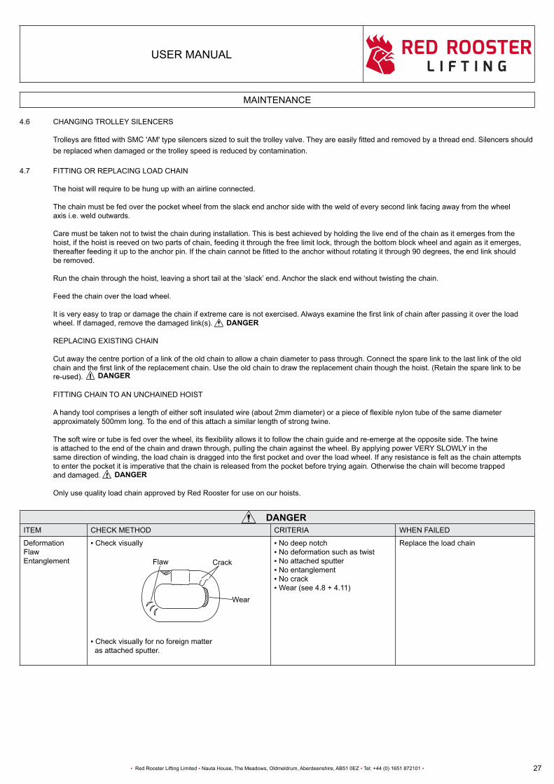
4.6 CHANGING TROLLEY SILENCERS
TrolleysarefittedwithSMC'AM'typesilencerssizedtosuitthetrolleyvalve.Theyareeasilyfittedandremovedbyathreadend.Silencersshould be replaced when damaged or the trolley speed is reduced by contamination. 4.7 FITTING OR REPLACING LOAD CHAIN The hoist will require to be hung up with an airline connected.
The chain must be fed over the pocket wheel from the slack end anchor side with the weld of every second link facing away from the wheel axis i.e. weld outwards.
Care must be taken not to twist the chain during installation. This is best achieved by holding the live end of the chain as it emerges from the hoist, if the hoist is reeved on two parts of chain, feeding it through the free limit lock, through the bottom block wheel and again as it emerges, thereafterfeedingituptotheanchorpin.Ifthechaincannotbefittedtotheanchorwithoutrotatingitthrough90degrees,theendlinkshould be removed.
Runthechainthroughthehoist,leavingashorttailatthe‘slack’end.Anchortheslackendwithouttwistingthechain.
Feed the chain over the load wheel.
Itisveryeasytotrapordamagethechainifextremecareisnotexercised.Alwaysexaminethefirstlinkofchainafterpassingitovertheload wheel. If damaged, remove the damaged link(s).
REPLACING EXISTING CHAIN Cut away the centre portion of a link of the old chain to allow a chain diameter to pass through. Connect the spare link to the last link of the old chainandthefirstlinkofthereplacementchain.Usetheoldchaintodrawthereplacementchainthoughthehoist.(Retainthesparelinktobe re-used).
FITTING CHAIN TO AN UNCHAINED HOIST
Ahandytoolcomprisesalengthofeithersoftinsulatedwire(about2mmdiameter)orapieceofflexiblenylontubeofthesamediameter approximately 500mm long. To the end of this attach a similar length of strong twine.
Thesoftwireortubeisfedoverthewheel,itsflexibilityallowsittofollowthechainguideandre-emergeattheoppositeside.Thetwine is attached to the end of the chain and drawn through, pulling the chain against the wheel. By applying power VERY SLOWLY in the samedirectionofwinding,theloadchainisdraggedintothefirstpocketandovertheloadwheel.Ifanyresistanceisfeltasthechainattempts to enter the pocket it is imperative that the chain is released from the pocket before trying again. Otherwise the chain will become trapped and damaged.
Only use quality load chain approved by Red Rooster for use on our hoists.
ITEM CHECK METHOD CRITERIA WHEN FAILED
DeformationFlawEntanglement
▪Checkvisually
▪Checkvisuallyfornoforeignmatter as attached sputter.
▪Nodeepnotch▪Nodeformationsuchastwist▪Noattachedsputter▪Noentanglement▪Nocrack▪Wear(see4.8+4.11)
Replace the load chain
DANGER
CrackFlaw
DANGER
DANGER
DANGER
Wear

28
USER MANUAL
▪ Red Rooster Lifting Limited ▪ Nauta House, The Meadows, Oldmeldrum, Aberdeenshire, AB51 0EZ ▪ Tel: +44 (0) 1651 872101 ▪
DANGER
HOIST COMPONENTS AND CHAIN
4.8 TYPES OF CHAIN Only the correct size and grade of load chain should be used. All chain is to EN818/7 - EN1677 standard
TCS-980 STANDARD HEAVY DUTY STAINLESS STEEL
RUD KITO RUD Nominal diameter: 6.3 + 0.1 / - 0.25 mm 6.3 + 0.3 / - 0.3 mm 6.3 + 0.1 / - 0.25 mm Pitch: 19.1 + 0.2 / - 0.1 mm 19.0 + 0.37 / - 0.00 mm 19.1 + 0.2 / - 0.10 mm Max dia at weld: 6.8 mm 6.8 mm 6.8 mm Min breaking force: 50.0 kN 50 kN 40 (G60) Kn Surface hardness: 500-650HV5 Grade 80T ca250HV5 Grade: EN818/7 ISO 3077 EN818-7 ISO 3077 DIN5684 - 8 + EN818/7 ISO 3077
NOTE: SparkresistanthoistsarefittedwithKITOnickelplatedheavydutychainor60stainlesssteelchain.Pleaserefertosupplier.
Whensuppliednew,onlyqualitychainfromareputablesupplierhasbeenfittedtothehoist.Yoursupplierwillbeabletoofferreplacement chain of like quality.
4.9 EMERGENCY LOWERING In the event of a main air supply failure Red Rooster pneumatic hoists will stop hoisting or lowering and the springs on the disc brake will automatically close the brake holding the load in position.
The next steps will depend on whether the load is being lifted at the time, how long it will be until the air supply is available again and if it is necessary and safe to travel / lower the load to a safe position.
If the problem is a burst hose, this can easily be replaced so there is no need to recover the load, but if the main compressor will not be operational for some time then a suspended load may need to be recovered to a safe position.
OPTIONS: 1) A secondary or back up compressor can be used as a temporary supply to move and or lower the load to a safe position.
2) Dependingontheloadandavailabilityofmanualrigginggeartheloadcanfirstbeliftedandtheairhoisthookdisconnected,thenthe load can be lowered to a safe position.
3) An emergency air supply from an air receiver or a high pressure cylinder and regulator set for 6 to 7 Bar pressure can be positioned within the working area of the hoist and the air supply hose connected via an on / off valve which can then be turned on to supply a limited amount of air to make the lift safe. This option will only allow for limited movement so try to choose the option that requires the least amount of running time.
If it is decided the safest course of action is to keep the hoist suspended the load then slings and shackles should be used to connect to the load from above (with a SWL equal or greater than the load being lifted by the hoist), to hold the load in case of brake slippage over a long period.
DANGER

29
USER MANUAL
▪ Red Rooster Lifting Limited ▪ Nauta House, The Meadows, Oldmeldrum, Aberdeenshire, AB51 0EZ ▪ Tel: +44 (0) 1651 872101 ▪
HOIST COMPONENTS AND CHAIN
4.10 TCS-980
CHAIN FITTINGS
TCS-980
HOIST PARTS
1 Hook Safety Latch
2 Upper Hook
3 Motor Section
4 Silencer Section
5 Valve Section
6 Brake Section
7 Chain
8 End Stopper
9 Gear Box
10 Chain Lever
11 Hook Safety Latch
12 Lower Hook
13 Cord Lever
14 Cord Control
15 Pendant Control
1 Chain
2 Welding Area
3 Install at 9th Link
4 Chain End Stop
5 Limit Lever
1
2
3
4
5
1
11
2
12
34
6
7
9
10
15
13
14
5
8
30
USER MANUAL
▪ Red Rooster Lifting Limited ▪ Nauta House, The Meadows, Oldmeldrum, Aberdeenshire, AB51 0EZ ▪ Tel: +44 (0) 1651 872101 ▪
SERVICE DATA
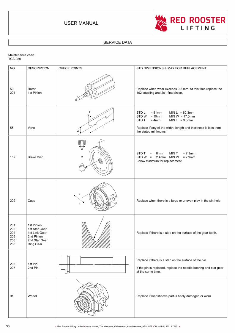
Maintenance chartTCS-980
NO. DESCRIPTION CHECK POINTS STD DIMENSIONS & MAX FOR REPLACEMENT
53201
Rotor1st Pinion
w
Replace when wear exceeds 0.2 mm. At this time replace the 102couplingand201firstpinion.
55 Vane
STD L = 81mm MIN L = 80.3mmSTD W = 19mm MIN W = 17.5mmSTD T = 4mm MIN T = 3.5mm
Replace if any of the width, length and thickness is less than the stated minimums.
152 Brake DiscSTD T = 8mm MIN T = 7.3mmSTD W = 2.4mm MIN W = 2.9mmBelow minimum for replacement.
209 Cage Replace when there is a large or uneven play in the pin hole.
201202204205206208
1st Pinion1st Star Gear1st Link Gear2nd Pinion2nd Star GearRing Gear
Replace if there is a step on the surface of the gear teeth.
203207
1st Pin2nd Pin
Replace if there is a step on the surface of the pin.
If the pin is replaced, replace the needle bearing and star gear at the same time.
91 Wheel Replace if loadsheave part is badly damaged or worn.
T
WL
T
W
31
USER MANUAL
▪ Red Rooster Lifting Limited ▪ Nauta House, The Meadows, Oldmeldrum, Aberdeenshire, AB51 0EZ ▪ Tel: +44 (0) 1651 872101 ▪
SERVICE DATA
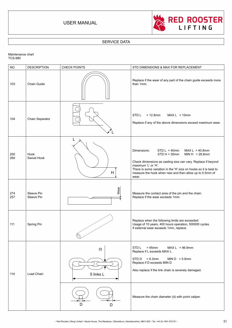
Maintenance chartTCS-980
NO. DESCRIPTION CHECK POINTS STD DIMENSIONS & MAX FOR REPLACEMENT
103 Chain GuideReplace if the wear of any part of the chain guide exceeds more than 1mm.
104 Chain SeparatorSTD L = 12.8mm MAX L = 15mm
Replace if any of the above dimensions exceed maximum wear.
250260
HookSwivel Hook
Dimensions: STD L = 40mm MAX L = 40.8mm STD H = 30mm MIN H = 28.8mm
Check dimensions as casting size can vary. Replace if beyond maximum‘L’or‘H’.There is some variation in the 'H' size on hooks so it is best to measure the hook when new and then allow up to 0.5mm of wear.
274257
Sleeve PinSleeve Pin
Measure the contact area of the pin and the chain.Replace if the wear exceeds 1mm.
111 Spring PinReplace when the following limits are exceeded:Usage of 10 years, 400 hours operation, 500000 cycles.If external wear exceeds 1mm, replace.
114 Load Chain 5 links L
D
STD L = 95mm MAX L = 96.9mmReplace if L exceeds MAX L.
STD D = 6.3mm MIN D = 5.9mmReplace if D exceeds MIN D
Also replace if the link chain is severely damaged.
Measure the chain diameter (d) with point caliper.
DD
L
Wea
r
L
H

32
USER MANUAL
▪ Red Rooster Lifting Limited ▪ Nauta House, The Meadows, Oldmeldrum, Aberdeenshire, AB51 0EZ ▪ Tel: +44 (0) 1651 872101 ▪
CAUTIONCAUTION
LAYING UP THE HOIST
5.1 LAYING UP THE HOIST
Whenever the hoist is unused for a period ( weekends, holidays or in store ), a little preparation will ensure that the hoist operates correctly andsafely,eitherbeforebeingputintoserviceforthefirsttimeorwhenbeingputbackintoserviceafteralayup.
SHORT LAY UP PERIOD (2 TO 90 DAYS):
Air hoists should be kept clean, lubricated and stored in a clean and dry location. When not in use seal off from the air supply inlet and run extra oil through the hoist as per lay up instructions. Wherever possible keep the hoist protected when in use and installed in an exposed location, protecting controls and hoses from damage.
Turn up the oil delivery rate of the lubricator to maximum and run the hoist for two minutes, thereby ensuring that the hoist motor and control valve are well lubricated. (This also helps to displace any water which may be lying in the hoist).
LONG TERM LAY UP PERIOD (3 MONTHS TO 12 MONTHS): ▪ Heavilylubricatethehoistasspecifiedabove. ▪ Ifthehoistiscontaminatedwithdirtorchemicals,washwithaproprietymildsolventordetergentandthoroughlyrinseoffwithfresh water.Allowtodryandspraylightlywithpenetratingfluid.
▪ Lubricatetheloadchain,limitshafts,safetylatches,andhookswivels.
▪ Disconnecttheairsupplyandplugtheinletport. ▪ Ifrequired,dismantlethechaincollector,pendant,airsetandtrolleyforstorage.
▪ Storeinadryventilatedarea.
▪ Securehoistinacrateorsuitablepallet. Transportation - Moving your Red Rooster hoist between locations. Carefully disconnect from suspension point and lower under control to ground level. Be sure that chain collector, valves and trolley drives are not damaged. Carefully lay the pendant on top of the hoist making sure tubes or hoses are not damaged. Secure the hoist and chain to the shipping container or pallet.
For long term storage corrosion inhibitors (wax coatings) can also be applied to suitable surfaces and then removed before use.
Before connecting the air supply line to the hoist, pour 5 to 10 cc of Atlub air tool oil directly into the airline to ensure that oil is present in the motor startup.
If being stored long term especially outside ask for a copy of the full procedure - AHLU-15
CAUTIONCAUTION

33
USER MANUAL
▪ Red Rooster Lifting Limited ▪ Nauta House, The Meadows, Oldmeldrum, Aberdeenshire, AB51 0EZ ▪ Tel: +44 (0) 1651 872101 ▪
CHAIN COLLECTORS
6.1 When supplied new the chain bag or chain bucket will have been sized to suit the HOL of the hoist with spare capacity to allow for some bunchingupofthechain.Theuseofachaincollectorcanmaketheoperationofthehoistmoreefficientpreventingdangerousoccurrences with the chain getting caught or falling from the load being lifted as it mounts up on top of the load.
On hoists from 250 kg to 6 tonne PVC bags are used with chain sizes from 4 to 11.2mm diameter.
On hoists from 250 kg to 6 tonne with a high HOL and chain sizes over 11.2mm, galvanised chain collectors are used, with stainless steel buckets being used on ATEX hoists and in areas of high corrosion.
On arrival at site the load chain should be removed from the chain collector either manually or by carefully running out of the hoist checking for snagging. The chain should then be run back into the collector by the hoist checking there are no twists in the chain that the bottom hook is not twisted through the chain fall on multi-fall blocks.
Hoists with long drops of chain and heavy loads in the chain collectors will require a secondary suspension point to hold the hoist in a vertical position when unloaded. These may be as shown in section 1.8 or a secondary trolley on a runway beam.
If operating without a chain collector the slack end of the chain may catch or get caught on top of a load. Always make sure the unloaded chain is running freely.
▪ Donotexceedthechaincollectorcapacity.
▪ Whentheloadchainisdryitmaynotrunfreelyintothechaincollectorandoverfillthecollector,sothechainmustbekeptlubricatedto prevent it running out of the collector.
▪ Makesurethechaincollectorbracketshavenotbeendamagedduringinstallation.
▪ Makesurethechaincollectorisfreetomovewhenthehoistisloadedandun-loaded.
▪ Makesurethebottomhookdoesnotconnectwiththechaincollector.Limittheliftingheightofthebottomhookifnecessary.
▪ ForanyassistancerequiredonchaincollectorspleasecontactRedRoosterIndustrial(UK)Ltd.
DANGER
CAUTIONCAUTION
CAUTIONCAUTION
PART NO TCR
-250
TCR
-500
/2
TCS
-50O
TCR
-500
TCS
-980
/2
TCR
-100
0/2
TCR
-100
0
TCR
-200
0/2
TCR
-300
0
TCR
-600
0/2
BAG1 13 7
BAG2 25 13
BAG3 6 3 6 3
BAG4 9 4.5 9 4.5
BAG5 13 7 13 7
BAG6 12 6
BAG7 20 10
BAG8 10 5
MAX HOL (m)
HOIST

34
USER MANUAL
▪ Red Rooster Lifting Limited ▪ Nauta House, The Meadows, Oldmeldrum, Aberdeenshire, AB51 0EZ ▪ Tel: +44 (0) 1651 872101 ▪
CHAIN COLLECTORS
TCS-980
TCS-980
1 M8 x 65
2 M6 x 25
3 Chain Bag
3
2
1

35
USER MANUAL
▪ Red Rooster Lifting Limited ▪ Nauta House, The Meadows, Oldmeldrum, Aberdeenshire, AB51 0EZ ▪ Tel: +44 (0) 1651 872101 ▪
SPEED ADJUSTMENT
7.1 SPEED ADJUSTMENT EveryTCShoistischeckedatthefactorytoensurethemaximumhoistingspeedisinaccordancewiththespecification. CORD CONTROL HOIST
The speed of the hoist is proportional to the amount of downward movement in the control cord, which via the cord lever controls the amount by which the valve is opened.
For the pendant control, adjust the speed by varying the amount the lever is depressed. By depressing the lever slightly, you will be able to control the hoists motions slowly with more precision. By depressing the lever further, the speed of the hoist will be increased until the lever is fully depressed.
The TCS series is equipped with a speed adjustment mechanism. If you feel the lifting or lowering speed is too fast, the speed can be adjusted slower as needed variably. Also please note that the speed can be adjusted separately for lifting and lowering.
HOW TO ADJUST THE SPEED
Referring to the diagram below, looking at the hoist from the valve side, the speed adjustment screw for lifting is on the RIGHT, and the lowering adjustment screw is on the LEFT. Both adjustment screw are covered with a red plastic cover and can be removed using a pair of pliers. Behind theplasticcoverisa'minus'grooveandcanbeadjustedusingastandardflatscrewdriver.Inrelationtotheairhoist,asshowninthedrawing below, the vertical direction means the highest speed, and the horizontal position means the lowest speed. (Note: the hoist will stop if the speed is adjusted too low) The adjustment can be made between these positions. Adjustthespeedonlywhenthehoistisinstopmode.Iftheadjustmentismadewhenthehoistismoving,itwillbedifficulttorotatethescrew since the air pressure increase the friction on the o-ring.
NOTE:Whenadjustingthespeedadjustmentscrew,theo-ringfrictionmaymaketherotationofthescrewdifficult,butthisisnotabnormal. NOTE: The speed adjustment mechanism is set at the highest speed when shipped from the factory.
SLOW FAST SLOW FAST
1 Adjust screw lowering speed
2 Adjust screw lifting speed
3 Highest speed setting
4 Lowest speed setting
1 2 3 4

36
USER MANUAL
▪ Red Rooster Lifting Limited ▪ Nauta House, The Meadows, Oldmeldrum, Aberdeenshire, AB51 0EZ ▪ Tel: +44 (0) 1651 872101 ▪
OPERATIONAL BREAKDOWN / TROUBLESHOOTING THE TCR & TCS HOIST & TROLLEY
8.1 We list below a number of faults which may occur during use, together with the probable cause and the cure. If you experience a fault and cannotidentifythecause,orifyoudonotfeelconfidenttoremedythefault,pleasereverttoyourhoistsupplier.
Description of fault noted Possible cause of fault Remedy
Hoist or trolley fails to start(when newly installed)
Air supply switched off
Damaged or kinked pendant hose
Emergency stop actuated
Control valve sticking
Air pressure too low
Hand control is faulty
Switch on air supply.
Disconnect pendant from control valve and check if there is pressure. Replace as necessary.
Re-set emergency stop.
With air supply switched off, open and close the valve using a spanner on the limit lever. Do not use excessive force. If this fails, refer to dealer.
Increase air pressure to the required valve. (6 bar)
Have hand control repaired.
Hoist or trolley starts but slows down and stops (when newly installed)
Inadequate air supply
Regulator set in excess of 7 bar
Air supply hoses leaking or loose
Silencer is clogged
Check compressor output against hoist requirements.Check air hose size against table.Ensurefittingsarematchedtohosesize.Replace incorrect items.
Reduce to 6 bar / Fit regulator.
Check connections of air supply hose and control hoses and connect properly.
Replace or clean silencer elements, improve air quality if necessary.
Hoist or trolley starts but will not stop Sticking valve on pendant
Contamination within the control valve
Clean and lubricate valve, replace if necessary.
Dismantle, clean and lubricate .
Hoist or trolley sometimes refuses to start
Worn vanes or damaged vane springs
Motor has run dry
Control valve on motor
Dismantle and replace as necessary.
Lubricate motor, check oiler.
Have control valve replaced / serviced.
Load chain jumps or makes a clicking sound
Worn load chain or guide
Chain twisted
Chain sprocket worn
Dismantle and replace as required.
Incorrectlyfitted-removeandrefit(examine).Bottom block twisted through chain parts (2 fall models only).
Replace chain sprocket, check chain guide, replace if necessary.
Motor‘stutters’andrecoversperiodically
Excessive moisture in air supply Increaseinfiltrationorfitadryer.
Premature wear in load chain Inadequate lubrication of load chain
Support Vibration
Hoist constantly operating at close headroom
Lubricate the chain.
Find cause of vibration.
Fit a ball bearing swivel below the hook.
Trolley fails to move Trolley adjustment Obstruction on beamHose festoon jammed
Adjust spacers and tie barsRemove obstructionAdjust/repair festoon

37
USER MANUAL
▪ Red Rooster Lifting Limited ▪ Nauta House, The Meadows, Oldmeldrum, Aberdeenshire, AB51 0EZ ▪ Tel: +44 (0) 1651 872101 ▪
PERIODIC EXAMINATION AND TESTING
9.1 EXAMINATION
UK & European Law requires that a thorough examination of the hoist should be carried out by a competent person:
▪ Beforebeingputintoservice. ▪ Atafrequencynotexceeding12months(6monthsforequipmentusedoffshore). ▪ Afterbeingputintoserviceatanewsite. ▪ Afterinvolvementinanaccidentordangerousoccurrence. ▪ Afterasignificantchangeintheconditionsofuse. ▪ Afterlongperiodsoutofuse(timenotspecified).
Liftingoperationsandliftingequipmentregulations1998,section9refers.(LOLER1998№2307)
The record of such examination must be retained for as long as the employer continues to operate the equipment. The regulations also callupontheemployertocarryoutariskassessment;toadjustthefrequencyofinspectionaccordingtothepotentialrisk,todeterminethe nature of inspections and to ensure that the persons carrying out the inspection are competent to do so.
9.2 SIX MONTHLY OFFSHORE INSPECTION Arrangetohavethehoistexaminedbyapersonspecificallytrainedandexperiencedintheexaminationofliftingmachines.Thiscanbedone by a Red Rooster engineer or an independent competent person. Ensure that the party is operating to a detailed inspection procedure or code of practice.
SERVICE
We would recommend the hoist is returned every 5 years for a full inspection and service.
9.3 TESTING LOLER 98, section 4 calls for the employer to ensure that the hoist is of adequate strength and stability for each load. No frequencies or test or proofloadsarespecified.
In the case of the TCR, TCS + TNC hoists the hoist is functionally tested with a proof load of 125% of the safe working load prior to delivery (Testcertificaterefers). It is recommended that the test is repeated along with a thorough examination if the hoist is substantially repaired (i.e. any repair which may affect the hoists ability to lift, lower and sustain a load).
REPEAT PROOF LOAD TESTING OF THE HOIST SHOULD BE AVOIDED
NOTE! Ifyourhoistisa“sparkresistant”version;checkthebronzecoatingofthelowerandupperhookonsignsofwear.AwornoutcoatingisNOT spark resistant anymore and can cause dangerous situations. Therefore let the bronze coating be renewed by your supplier in time.

38
USER MANUAL
▪ Red Rooster Lifting Limited ▪ Nauta House, The Meadows, Oldmeldrum, Aberdeenshire, AB51 0EZ ▪ Tel: +44 (0) 1651 872101 ▪
DUTY RATINGS
10.1 FEM9.511classifiesthetheoreticalloadingconditionsandoperatingtimeinhoursperday.
FEM9.755classifiesthetheoreticaldurationofserviceforsafeoperation.
APPLICATION OF FEM RULES TO PNEUMATIC HOISTS
With most mechanical equipment, the limiting factor with regard to operating time is that of HEAT GENERATION. Forexample,anelectricmotorifnotperiodicallyalloweda‘restperiod’toallowittocooldownaftereachperiodofusewillceasetofunctiondue to irreversible damage arising as a consequence of the heat.
Air motors perform differently. Although heat is generated, providing that the motor is properly lubricated, no damage will ensue. The expanding air at the outlet manifold also has a cooling effect on the motor.
As a result pneumatic motors are commonly referred to as 100% duty rated or continuous rated, which means simply that they may be used continuously without a cooling down period and without damage arising as a consequence.
Incorporated into the TCS hoist are three classes of components:
1. Sacrificialcomponents-Thesecomponentsaredesignedtoincurweartoeitherprotectothercomponentsortofunctionby means of friction generation. They require periodic inspection and replacement and comprise of the rotor vanes and the brake disc. Inadequate lubrication seriously reduces the life expectancy of the vanes.
2. Load chain - Whilst adequate lubrication of the load chain will reduce friction and thereby limit the wear occurring between the bearing points of adjacent links, it will not totally eliminate it. Hence it will require regular inspection and will also require replacement within the service life of the hoist.
3. Structural and mechanical components - These comprise all other parts of the hoist, including gearbox and bearings, rotor and housing, valve, hooks, pins etc. A theoretical service life for every component has been calculated (available on request). For the purposes of the summary, the SHORTEST service life of any component has been included.
10.2 TABLES OF DUTIES - TCS Hoist
*Shortest duration stated.
IMPORTANT NOTES
A hoist is deemed to be operating when it is in motion. All ratings are based on a clean, dry, air supply and correct lubrication. Loadchainmustbetomanufacturer’sspecification. Special chains are excluded (consult your supplier). Mode of use must be in accordance with manufacturer’s recommendation.
FEM standard For all mentioned TCS models
FEM 9.511 1 Am (M4)
Theoretical duration of service
FEM 9.755
Sacrificialcomponents
Load chain
Structural & mechanical components*
1Am (M4)800 to 6300 hours
2M (M5)1600 to 12500 hours
2M (M5)1600 to 12500 hours

39
USER MANUAL
▪ Red Rooster Lifting Limited ▪ Nauta House, The Meadows, Oldmeldrum, Aberdeenshire, AB51 0EZ ▪ Tel: +44 (0) 1651 872101 ▪
EXPLOSION PROTECTION
11.1 In Europe and several other parts of the world (check the rules in your own country) the use of non-electrical equipment in hazardous areas is covered by the ATEX 2014/34/EU Directive. This is split into two categories of equipment, Group 1 - Mining and Group 2 - above ground. Red Rooster hoists are suitable for Group 2 areas as well as Group 1 Mining category M(2) - M2c
AllstandardRedRoosterhoistsandtrolleysfrom250kgto50tonnecanbecertifiedforuseinZone2areasandwithadditionalprotectionbuilt intothehoisttheycanbecertifiedforZone1use.Thepreparationworkrequiredtobecarriedoutonourhoistsandtrolleysvariesonthe protection level required by the customer. With the information on where the hoist will be operating, we prepare hoists to be suitable for the Zone, gas group and temperature rating.
Hoistsandtrolleyscanbefittedwithdifferenttypesofloadchain,bronzesprayedhooks,stainlesssteelsafetycatches,andstainlesssteelname platesamongseveralothermodifications.TrolleyscanbefittedwithbronzewheelsalongwithATEXratedairmotors,gearboxesandvalves.
Standard Zone 2 (Gases) Zone 22 (Dust) rating - Group II 3 GD c IIA T4 (135°C)
Standard Zone 1 (Gases) Zone 21 (Dust) rating - Group II 2 GD c IIB T4 (135°C) (Other gas groups and temperature ratings are available)
Mining - Group 1 - Category M(2) - M2c (Mechanical equipment de-energised) These ratings cover air hoists, air trolleys, manual trolleys and air powered wire rope hoists.
▪ Duringusetheoperatormustavoidloadsorthebottomhookimpactingwithsurroundingsteelequipmentandstructuralsteel whichmayresultinsparkingorfrictionalsparkscausedbydraggingloadspastfixedstructures.
▪ Anyimpactsinvolvinglightmetalorcastironshouldbeavoidedandthesematerialseitherprotectedorremovedfromthearea.
▪ DamagedorbadlycorrodedcoatingsorchainshouldbereplacedorrepairedtokeepuptheATEXratingoftheequipment.For assistance contact RRIUK.
▪ Earthingofhoistsisnotusuallyrequiredasthehookconnectiontostructureallowsthehoisttoconnecttoearth. ▪ Therunningsurfacesofbeamsandcranesshouldnotbepaintedtoallowwheelstoearthtothestructure.
▪ Stainlesssteel‘C’tracksystemsshouldbeappliedwithanearthwiretoconnectontothestructure.
▪ Plasticjunctionboxesshouldonlybecleanedwithwaterandacleanclothtoreduceanyelectrostaticchargecomingfromthe rubbing of the plastic surface.
▪ Dustshouldnotbeallowedtoaccumulateonthehoist,trolley,craneorjunctionboxes.
DANGER

40
USER MANUAL
▪ Red Rooster Lifting Limited ▪ Nauta House, The Meadows, Oldmeldrum, Aberdeenshire, AB51 0EZ ▪ Tel: +44 (0) 1651 872101 ▪
TECHNICAL SPECIFICATION - STANDARD 4 WHEEL TROLLEYS
12.1 TABLE 1 Lubricator recommended drop rate per minute
TROLLEY CAPACITY CONTINUOUS OPERATION INTERMITTENT OPERATION0.25 + 0.5 Tonne 4 - 5 9 - 12
0.5 to 6 Tonne 4 - 5 9 - 12
9 to 25 Tonne 5 - 6 10 - 12
TABLE 2
Beamtrolleyflangerangesforfourwheeltrolleys
FLANGE WIDTH RANGE
LIFTING CAPACITY (TONNES)0.25 to 2 Tonne 3 Tonne 6 Tonne 9 Tonne 10 Tonne
R1 55 to 140 mm 80 to 160 mm 90 to 160 mm 110 to 180 mm 110 to 180 mm
R2 140 to 220 mm 160 to 230 mm 160 to 230 mm 180 to 240 mm 180 to 240 mm
R3 220 to 330 mm 230 to 300 mm 230 to 300 mm 240 to 300 mm 240 to 300 mm
FLANGE WIDTH RANGE
LIFTING CAPACITY (TONNES)12 Tonne 15 Tonne 20 Tonne 25 Tonne
R1 110 to 180 mm 110 to 180 mm 130 to 200 mm 130 to 200 mm
R2 180 to 240 mm 180 to 240 mm 200 to 260 mm 200 to 260 mm
R3 240 to 300 mm 240 to 300 mm 260 to 320 mm 260 to 320 mm
TABLE 3
LIFTING CAPACITY
TROLLEY SPEEDSAIR CONSUMPTION
STANDARD OPTION ATEX0.25 to 2 Tonne 9 m/min 14 m/min 6 m/min 25 l/sec at 6 Bar
3 to 6 Tonne 6 m/min 14 m/min 6 m/min 50 l/sec at 6 Bar
9 to 12 Tonne 8 m/min N/A N/A 50 l/sec at 6 Bar
15 Tonne 6 m/min N/A N/A 50 l/sec at 6 Bar
20 to 25 Tonne 4 m/min N/A N/A 50 l/sec at 6 Bar
TABLE 4
LIFTING CAPACITY MINIMUM BEND RADIUS
0.25 to 2 Tonne 1.5 m
3 to 12 Tonne 2.5 m
15 to 25 Tonne 3.0 m

41
USER MANUAL
▪ Red Rooster Lifting Limited ▪ Nauta House, The Meadows, Oldmeldrum, Aberdeenshire, AB51 0EZ ▪ Tel: +44 (0) 1651 872101 ▪ 1
REV.DESCRIPTIONPART NUMBERQTYITEM02TE Air Trolley (2TE/AT/4)DRG 1500-01110Air Hoist / 1TE Bottom BlockTCS 5001201TE Top EyeDRG 1500-3113
Title of project Material Weight
Checked by
Designed by
Approved by
Scale Title of part Part number
Revision number
Replaces draw
Surn
ame
Dat
e
Sign
atur
e0,98TE Hoist and Trolley 26/06/2014 - 45kg
Date
-
0
1:5 TCS 0,98/2F - 1AT/2T/4 DRG 1500-24
T. Mikolajewski
S. Przygoda
B. Aitken
red rooster Red Rooster Industrial (UK) Ltd,
Nauta House, The Meadows,Oldmeldrum, Aberdeenshire, AB51 0EZ
Tel: +44(0)1651 872101Main Fax: +44(0)1651 872098Sales Fax: +44(0)1651 871405
www.rriuk.com
Ø35
35 m
ax.
70Ø
21 55÷300 21 135
7153
030
� 40
23
205163
112235285
25
42123
1
3
2
All measurements are in mmInformation subject to change without notice
Image for illustration purposes only
AVAILABLE OPTIONS Marinespecification Special paint systems Collision bumpers ATEXzone1specification Chain collectors ( PVC, galvanised or stainless steel) Articulated trolley Low headroom units Rack & pinion drive Travel limits Air service units Festoon systems Radio control remote Optional travel speeds Beam brake
REV.DESCRIPTIONPART NUMBERQTYITEM02TE Air Trolley (2TE/AT/4)DRG 1500-01110Air Hoist / 1TE Bottom BlockTCS 5001201TE Top EyeDRG 1500-3113
Title of project Material Weight
Checked by
Designed by
Approved by
Scale Title of part Part number
Revision number
Replaces draw
Surn
ame
Dat
e
Sign
atur
e
0,98TE Hoist and Trolley 26/06/2014 - 45kgDate
-
0
1:5 TCS 0,98/2F - 1AT/2T/4 DRG 1500-24
T. Mikolajewski
S. Przygoda
B. Aitken
red rooster Red Rooster Industrial (UK) Ltd,
Nauta House, The Meadows,Oldmeldrum, Aberdeenshire, AB51 0EZ
Tel: +44(0)1651 872101Main Fax: +44(0)1651 872098Sales Fax: +44(0)1651 871405
www.rriuk.com
Ø35
35 m
ax.
70Ø
21 55÷300 21 135
7153
030
� 40
23
205163
112235285
25
42123
1
3
2
HOIST MODEL TCS-980-AT2SWLL 980 kgCHAIN FALLS 2LIFTING SPEED FULL LOAD 8.5 m/minLIFTING SPEED WITHOUT LOAD 16.0 m/minAIR CONSUMPTION (L/SEC) 28WORKING PRESSURE 6 bar AIR CONNECTION 1/2" BSPMINIMUM HOSE DIA. 1/2"WEIGHT 3M HOL & TROLLEY 45 kg ADDITIONAL METRE HOL 1.6 kg
TROLLEY MODEL AT2SG.A. DRAWING 1500-24FLANGERANGE 1RANGE 2RANGE 3
55-140
140-220220-300
STANDARD TROLLEY TEMP RANGE -10 to +50°COPTIONAL TROLLEY TEMP RANGE -20 to +70°CSTANDARD TRAVEL SPEED 9 m/minATEX ZONE 1 TRAVEL SPEED 6 m/minOPTIONAL TRAVEL SPEED 14 m/minWHEEL MATERIAL SteelATEX ZONE 1 WHEEL MATERIAL BronzeMINIMUM BEND RADIUS (M) 1.5NUMBER OF WHEELS 4DRIVEN WHEELS 2MAX AIR CONSUMPTION 25 l/secHOSE ID TROLLEY 1/2"
AT_S = STANDARD AT_ATX = ATEX
STANDARD FEATURES Toku rotary vane motor ATEXzone2specification Robust epicycle gearbox Failsafe automatic internal disc brake Choice of pendant controls or control stations Upper & lower limit switches Lightweight aluminium housing Internal silencing down to 83 dB(A) Alloy safety swivel hooks with safety catch Load chain of European manufacture to EN818-7 Trolleytosuitvariousflangeprofiles Anti-tilt & anti-drop plates Highefficiencymotorgearbox Heavy duty sealed wheel bearings Wheelprofiletosuitparallelortaperedflanges
ATEX ZONE 2 AS STANDARD
TCS-980-AT2SHIGH SPEED AIR HOIST & TROLLEY
RED ROOSTER LIFTINGNauta House, The Meadows T: +44 (0) 1651 872101Oldmeldrum, Aberdeenshire E: [email protected] Kingdom, AB51 0EZ W: www.redroosterlifting.com

42
USER MANUAL
▪ Red Rooster Lifting Limited ▪ Nauta House, The Meadows, Oldmeldrum, Aberdeenshire, AB51 0EZ ▪ Tel: +44 (0) 1651 872101 ▪

43
USER MANUAL
▪ Red Rooster Lifting Limited ▪ Nauta House, The Meadows, Oldmeldrum, Aberdeenshire, AB51 0EZ ▪ Tel: +44 (0) 1651 872101 ▪
DRAWINGS AND PARTS LISTS

44
USER MANUAL
▪ Red Rooster Lifting Limited ▪ Nauta House, The Meadows, Oldmeldrum, Aberdeenshire, AB51 0EZ ▪ Tel: +44 (0) 1651 872101 ▪
REV.
DES
CRIP
TIO
NPA
RT N
UM
BER
QTY
ITEM
02T
E Ai
r Tr
olle
y (2
TE/A
T/4)
DRG
150
0-01
11
0Ai
r H
oist
/ 1
TE B
otto
m B
lock
TCS
500
12
01T
E To
p Ey
eD
RG 1
500-
311
3Ti
tle o
f pr
ojec
tM
ater
ial
Wei
ght
Chec
ked
by
Des
igne
d by
Appr
oved
by
Scal
eTi
tle o
f pa
rtPa
rt n
umbe
rRevi
sion
num
ber
Repl
aces
dra
wSurname
Date
Signature
0,98
TE H
oist
and
Tro
lley
26/0
6/20
14-
45kg
Dat
e
- 0
1:5
TCS
0,98
/2F
- 1A
T/2T
/4D
RG 1
500-
24
T. M
ikol
ajew
ski
S. P
rzyg
oda
B. A
itken
red r
ooster
Re
d Ro
oste
r In
dust
rial (
UK)
Ltd
,N
auta
Hou
se, T
he M
eado
ws,
Old
mel
drum
, Abe
rdee
nshi
re, A
B51
0EZ
Tel:
+44
(0)1
651
8721
01M
ain
Fax:
+44
(0)1
651
8720
98Sa
les
Fax:
+44
(0)1
651
8714
05w
ww
.rriu
k.co
m
Ø3535 max.70 Ø
2155
÷30
021
135
71530 30
�40
23
205
163
112
235
285
25
4212
3
1 3 2

45
USER MANUAL
▪ Red Rooster Lifting Limited ▪ Nauta House, The Meadows, Oldmeldrum, Aberdeenshire, AB51 0EZ ▪ Tel: +44 (0) 1651 872101 ▪
Title
of
proj
ect
Mat
eria
lW
eigh
t
Chec
ked
by
Des
igne
d by
Appr
oved
by
Scal
eTi
tle o
f pa
rtPa
rt n
umbe
rRev
isio
n nu
mbe
r
Repl
aces
dra
w
Surname
Date
Signature
2TE
Hoi
st a
nd T
rolle
y20
13-0
7-16
-25
kgD
ate
- 0
1:5
2TE
Air
Trol
ley
(2TE
/AT/
4)D
RG 1
500-
01
T. M
ikol
ajew
ski
S. P
rzyg
oda
B. A
itken
red r
ooster
Red
Roo
ster
Ind
ustr
ial (
UK)
Ltd
,N
auta
Hou
se, Th
e M
eado
ws,
Old
mel
drum
, Abe
rdee
nshi
re, A
B51
0EZ
Tel:
+44
(0)1
651
8721
01M
ain
Fax:
+44
(0)1
651
8720
98Sa
les
Fax:
+44
(0)1
651
8714
05w
ww
.rriu
k.co
m
shee
t 1/
3
220
112
235
285
35 Ø35 max.70 Ø
2155
÷30
021
115
71
329 18
28
11
1325
5 6 7 825
13
12
4 6 7 8
2327
31
3420
2132
3334
2
14 15 16 17
1
1935
26
24
9 10
22
30
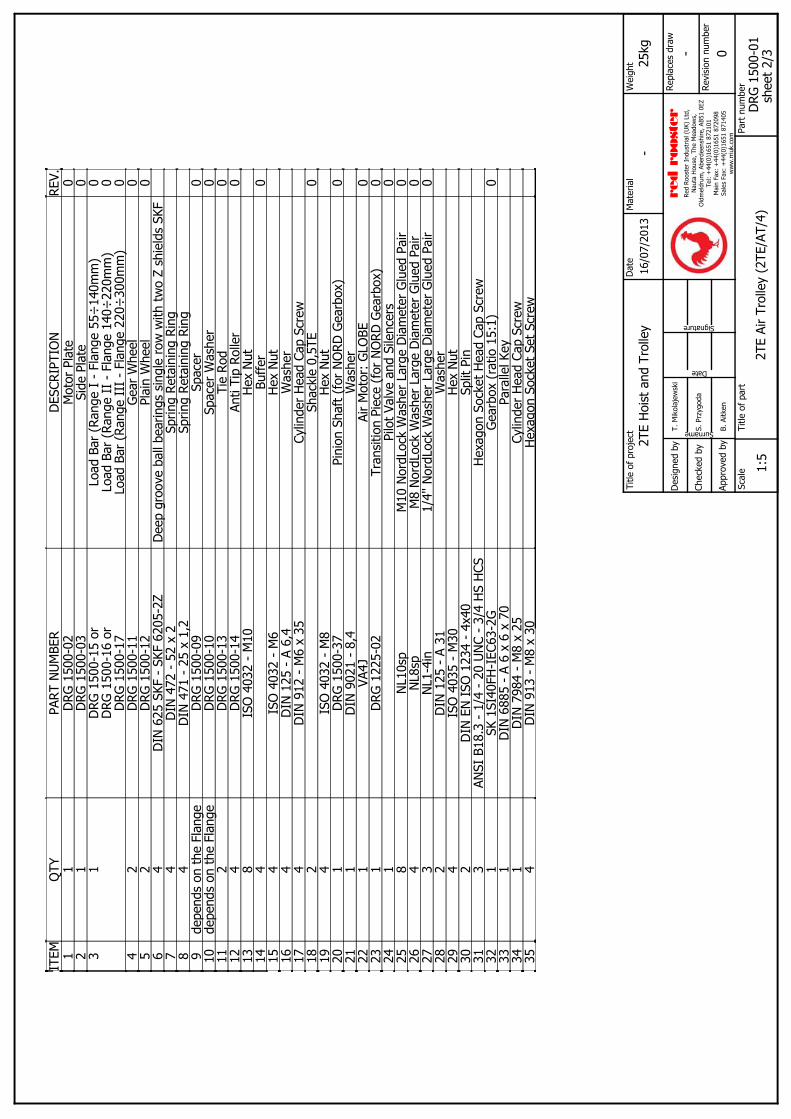
46
USER MANUAL
▪ Red Rooster Lifting Limited ▪ Nauta House, The Meadows, Oldmeldrum, Aberdeenshire, AB51 0EZ ▪ Tel: +44 (0) 1651 872101 ▪
REV.
DES
CRIP
TIO
NPA
RT N
UM
BER
QTY
ITEM
0M
otor
Pla
teD
RG 1
500-
021
10
Side
Pla
teD
RG 1
500-
031
20 0 0
Load
Bar
(Ra
nge
I -
Flan
ge 5
5÷14
0mm
)Lo
ad B
ar (
Rang
e II
- F
lang
e 14
0÷22
0mm
)Lo
ad B
ar (
Rang
e II
I -
Flan
ge 2
20÷
300m
m)
DRG
150
0-15
or
DRG
150
0-16
or
DRG
150
0-17
13
0G
ear
Whe
elD
RG 1
500-
112
40
Plai
n W
heel
DRG
150
0-12
25
Dee
p gr
oove
bal
l bea
rings
sin
gle
row
with
tw
o Z
shie
lds
SKF
DIN
625
SKF
- S
KF 6
205-
2Z4
6Sp
ring
Reta
inin
g Ri
ngD
IN 4
72 -
52
x 2
47
Sprin
g Re
tain
ing
Ring
DIN
471
- 2
5 x
1,2
48
0Sp
acer
DRG
150
0-09
depe
nds
on t
he F
lang
e9
0Sp
acer
Was
her
DRG
150
0-10
depe
nds
on t
he F
lang
e10
0Ti
e Ro
dD
RG 1
500-
132
110
Anti
Tip
Rolle
rD
RG 1
500-
144
12H
ex N
utIS
O 4
032
- M
108
130
Buff
er4
14H
ex N
utIS
O 4
032
- M
64
15W
ashe
rD
IN 1
25 -
A 6
,44
16Cy
linde
r H
ead
Cap
Scre
wD
IN 9
12 -
M6
x 35
417
0Sh
ackl
e 0,
5TE
218
Hex
Nut
ISO
403
2 -
M8
419
0Pi
nion
Sha
ft (
for
NO
RD G
earb
ox)
DRG
150
0-37
120
Was
her
DIN
902
1 -
8,4
121
0Ai
r M
otor
: G
LOBE
VA4J
122
0Tr
ansi
tion
Piec
e (f
or N
ORD
Gea
rbox
)D
RG 1
225-
021
230
Pilo
t Va
lve
and
Sile
ncer
s1
240
M10
Nor
dLoc
k W
ashe
r La
rge
Dia
met
er G
lued
Pai
rN
L10s
p8
250
M8
Nor
dLoc
k W
ashe
r La
rge
Dia
met
er G
lued
Pai
rN
L8sp
426
01/
4'' N
ordL
ock
Was
her
Larg
e D
iam
eter
Glu
ed P
air
NL1
-4in
327
Was
her
DIN
125
- A
31
228
Hex
Nut
ISO
403
5 -
M30
429
Split
Pin
DIN
EN
ISO
123
4 -
4x40
230
Hex
agon
Soc
ket
Hea
d Ca
p Sc
rew
ANSI
B18
.3 -
1/4
- 2
0 U
NC
- 3/
4 H
S H
CS3
310
Gea
rbox
(ra
tio 1
5:1)
SK 1
SI40
FH-I
EC63
-2G
132
Para
llel K
eyD
IN 6
885
- A
6 x
6 x
701
33Cy
linde
r H
ead
Cap
Scre
wD
IN 7
984
- M
8 x
251
34H
exa g
on S
ocke
t Se
t Sc
rew
DIN
913
- M
8 x
304
35
Title
of
proj
ect
Mat
eria
lW
eigh
t
Chec
ked
by
Des
igne
d by
Appr
oved
by
Scal
eTi
tle o
f pa
rtPa
rt n
umbe
rRevi
sion
num
ber
Repl
aces
dra
wSurname
Date
Signature
2TE
Hoi
st a
nd T
rolle
y16
/07/
2013
-25
kgD
ate
- 0
1:5
2TE
Air
Trol
ley
(2TE
/AT/
4)D
RG 1
500-
01
T. M
ikol
ajew
ski
S. P
rzyg
oda
B. A
itken
red r
ooster
Re
d Ro
oste
r In
dust
rial (
UK)
Ltd
,N
auta
Hou
se, T
he M
eado
ws,
Old
mel
drum
, Abe
rdee
nshi
re, A
B51
0EZ
Tel:
+44
(0)1
651
8721
01M
ain
Fax:
+44
(0)1
651
8720
98Sa
les
Fax:
+44
(0)1
651
8714
05w
ww
.rriu
k.co
m
shee
t 2/
3

47
USER MANUAL
▪ Red Rooster Lifting Limited ▪ Nauta House, The Meadows, Oldmeldrum, Aberdeenshire, AB51 0EZ ▪ Tel: +44 (0) 1651 872101 ▪
Brake Gears Suspension Body - TCS-98010.10.13

48
USER MANUAL
▪ Red Rooster Lifting Limited ▪ Nauta House, The Meadows, Oldmeldrum, Aberdeenshire, AB51 0EZ ▪ Tel: +44 (0) 1651 872101 ▪
Brake Gears Suspension Body - TCS-98010.10.13
Fig. No.
Part Number Part Name Parts Per Hoist
100 426230A00 CENTRE HOUSING 1
101 426230A50 LOAD SHEAVE 1
102 426230200 COUPLING 1
103 426230350 CHAIN GUIDE 1
104 426230360 CHAIN SEPARATOR 1
105 130106009 BEARING 6008ZZ 2
106 131706020 HEX SOCKET HEAD CAP SCREW M6X20 4
107 132106006 HEX SOCKET SET SCREW M6X6 1
108 131103006 O-RING S-8 1
109 131103052 O-RING S-90 1
110 131117043 O-RING AS568-043 1
111 130608060 SPRING PIN 8X60 2
114 AHC63/80 CHAIN 6.3mm HOL
150 426320410 BRAKE COVER 1
151 426230400 BRAKE PISTON 1
152 426230430 BRAKE DISC 1
153 130802213 DISC SPRING 6
154 137301065 NAME PLATE 1
155 131706045 HEX SOCKET HEAD CAP SCREW M6X45 4
156 132105005 HEX SOCKET SET SCREW M5X5 1
157 131103052 O-RING S-90 1
158 131103045 O-RING S-65 1
200 426230310 GEAR CASE 1
201 426230A60 FIRST PINION 1
202 426230A70 FIRST STAR GEAR 3
203 426230A80 FIRST PIN 3
204 426230E10 FIRST RING GEAR 1
205 426230E20 SECOND PINION 1
206 426230E30 SECOND STAR GEAR 3
207 426230E40 SECOND PIN 3
208 426230E50 SECOND RING GEAR 1
209 426230240 CAGE 1
210 426230890 LOCK SCREW 1
211 426230900 BRAKE PLATE 1
212 130113001 BEARING 6009 2
213 130120004 BEARING EE-4 1
214 130104006 BEARING 6005 1
215 130131020 NEEDLE BEARING TA1020Z 3
216 130131212 NEEDLE BEARING TA1212 3
217 131706020 HEX SOCKET HEAD CAP SCREW M6X20 3
218 131908015 HEX SOCKET BUTTON SCREW M8X15 1
219 131307012 WASHER M12 3
220 131307008 WASHER M8 1
221 131103006 O-RING S-8 1
222 131103052 0RING S-90 1
223 130606015 SPRING PIN 3X14 2
224 130606015 SPRING PIN 6X15 2
225 130302012 RETAINING RING S-12 3
250 426261S20 UPPER HOOK 1
Fig. No.
Part Number Part Name Parts Per Hoist
251 426221S30 HOOK SAFETY CLAW 1
252 130802258 HOOK SPRING 1
253 131705035 HEX SOCKET HEAD CAP SCREW M5X35 1
254 134501005 U-NUT M5 1
255 426251570 HOOK END PIECE 1
256 131706020 HEX SOCKET HEAD CAP SCREW M6X20 2
257 426224580 HOOK JOINT BOLT 1
258 131307006 WASHER M6 1
259 134501006 U-NUT M6 1
260 426221S20 SWIVEL HOOK 1
261 426221S30 HOOK SAFETY CLAW 1
262 130802258 HOOK SPRING 1
263 131705035 HEX SOCKET HEAD CAP SCREW M5X35 1
264 134501005 U-NUT M5 1
270 426251590 HOOK CASE 1
271 420846PY0 SIWVEL HOOK PLUG 1
272 420846PW0 SWIVEL HOOK OUTER RACE 1
273 426251F70 FREE CHAIN WHEEL 1
274 1301120036 BEARING 6302ZZ 2
275 130502020 STEEL BALL 5/16 8
276 131706035 HEX SOCKET HEAD CAP SCREW M6X35 2
278 134501006 U-NUT M6 2
284 420620JF0 CHAIN DOWN STOPPER 2
285 131705022 HEX SOCKET HEAD CAP SCREW M5X22 2
286 134401005 HEX NUT M5 2
287 131301005 SPRING WASHER M5 2

49
USER MANUAL
▪ Red Rooster Lifting Limited ▪ Nauta House, The Meadows, Oldmeldrum, Aberdeenshire, AB51 0EZ ▪ Tel: +44 (0) 1651 872101 ▪
Motor Valve Body - TCS-980 (Pendant)10.10.13

50
USER MANUAL
▪ Red Rooster Lifting Limited ▪ Nauta House, The Meadows, Oldmeldrum, Aberdeenshire, AB51 0EZ ▪ Tel: +44 (0) 1651 872101 ▪
Motor Valve Body - TCS-980 (Pendant)10.10.13
Fig. No.
Part Number Part Name Parts Per Hoist
001 420215VB0 THROTTLE VALVE 2
002 426320E90 VALVE BUSHING (U) 1
003 426230F00 VALVE BUSHING (D) 1
004 426230C70 SPRING SEAT 2
005 426230A20 VALVE CAP 2
006 426230060 VA;VE BODY 1
007 426230A30 BUSH CAP 2
008 426230C60 PISTON 2
009 426230810 EXHAUST PLATE 1
010 137402023 SILENCER (S) 4
011 426230A10 ADJUST CAP 2
012 134703070 INLET BUSHING 1
013 136803032 NET SCREEN 1
014 130802221 VALVE SPRING 2
015 130802224 SPRING 26X20X2.6 2
016 136102165 VALVE GASKET 1
017 130219705 DU BUSH DUB0705 2
018 131705050 HEX SOCKET HEAD CAP SCREW M5X50 4
019 131905010 HEX SOCKET BUTTON SCREW M5X10 2
020 132105005 HEX SOCKET SET SCREW M5X5 2
021 131103005 O-RING S-7 2
022 131103013 O-RING S-15 2
023 131103016 O-RING S-20 4
024 131103017 O-RING S-22 2
025 131117023 O-RING AS568-023 2
026 131118012 O-RING AS568-012 (HS90) 2
027 131103011 O-RING S-12.5 2
028 130602004 SPRING PIN 2X4 4
029 130604010 SPRING PIN 4X10 2
030 130301032 RETAINING RING S-12 2
031 130301032 RETAINING RING H-32 2
032 130301025 RETAINING RING H-25 2
050 426230790 MOTOR CASE 1
051 426230180 REAR PLATE 1
052 426230160 CYLINDER 1
053 426230150 ROTOR 1
054 426230170 FRONT PLATE 1
055 137102032 VANE 8
056 130802212 LIFT SPRING 8
057 426230460 LIMIT SHAFT 1
058 426230A40 LIMIT SHAFT BUSHING 1
059 426230140 LIMIT LEVER 1
060 130128104 BEARING MR104ZZ 2
061 426230120 ROLLER SHAFT 2
062 426251110 CHAIN LEVER 1
063 136102166 MOTOR GASKET 1
064 137402024 SILENCER (M) 1
065 130104003 BEARING 6002 2
066 130151210 NEEDLE BEARING TLA1210 2
Fig. No.
Part Number Part Name Parts Per Hoist
067 131706020 HEX SOCKET HEAD CAP SCREW M6X20 3
068 131708110 HEX SOCKET HEAD CAP SCREW M8X110 1
069 131706014 HEX SOCKET HEAD CAP SCREW M6X14 2
070 131103012 O-RING S-14 2
071 131103019 O-RING S-24 1
072 131102009 O-RING G-65 1
073 130604016 SPRING PIN 4X16 1
075 130603005 SPRING PIN 3X5 1
076 130302015 RETAINING RING S-15 1
077 130301028 RETAINING RING H-28 1
078 130790008 SNAP PIN 8 1
079 130303003 RETAINING RING E-3 4
350 426230470 UNDER COVER 1
351 137402033 PIROT SILENCER 1
352 131705030 HEX SOCKET HEAD CAP SCREW M5X30 1
353 131705020 HEX SOCKET HEAD CAP SCREW M5X20 2
354 132105016 HEX SOCKET SET SCREW M5X16 2
355 132105005 HEX SOCKET SET SCREW M5X5 1
356 132905206 CROSS HEAD FLAT MACHINE SCREW M5X6
3
357 134403205 HEX NUT M5 2
358 131103004 O-RING S-6 3
365 131705010 HEX SOCKET HEAD CAP SCREW M5X10 1
366 131307005 WASHER M5 1

51
USER MANUAL
▪ Red Rooster Lifting Limited ▪ Nauta House, The Meadows, Oldmeldrum, Aberdeenshire, AB51 0EZ ▪ Tel: +44 (0) 1651 872101 ▪
Motor Valve Body - TCS-980 (Cord)10.10.13

52
USER MANUAL
▪ Red Rooster Lifting Limited ▪ Nauta House, The Meadows, Oldmeldrum, Aberdeenshire, AB51 0EZ ▪ Tel: +44 (0) 1651 872101 ▪
Motor Valve Body - TCS-980 (Cord)10.10.13
Fig. No.
Part Number Part Name Parts Per Hoist
001 420215VB0 THROTTLE VALVE 2
002 426320E90 VALVE BUSHING (U) 1
003 426230F00 VALVE BUSHING (D) 1
004 426230C70 SPRING SEAT 2
005 426230A20 VALVE CAP 2
006 426230060 VA;VE BODY 1
007 426230A30 BUSH CAP 2
008 426230C60 PISTON 2
009 426230810 EXHAUST PLATE 1
010 137402023 SILENCER (S) 4
011 426230A10 ADJUST CAP 2
012 134703070 INLET BUSHING 1
013 136803032 NET SCREEN 1
014 130802221 VALVE SPRING 2
015 130802224 SPRING 26X20X2.6 2
016 136102165 VALVE GASKET 1
017 130219705 DU BUSH DUB0705 2
018 131705050 HEX SOCKET HEAD CAP SCREW M5X50 4
019 131905010 HEX SOCKET BUTTON SCREW M5X10 2
020 132105005 HEX SOCKET SET SCREW M5X5 2
021 131103005 O-RING S-7 2
022 131103013 O-RING S-15 2
023 131103016 O-RING S-20 4
024 131103017 O-RING S-22 2
025 131117023 O-RING AS568-023 2
026 131118012 O-RING AS568-012 (HS90) 2
027 131103011 O-RING S-12.5 2
028 130602004 SPRING PIN 2X4 4
029 130604010 SPRING PIN 4X10 2
030 130301032 RETAINING RING S-12 2
031 130301032 RETAINING RING H-32 2
032 130301025 RETAINING RING H-25 2
050 426230790 MOTOR CASE 1
051 426230180 REAR PLATE 1
052 426230160 CYLINDER 1
053 426230150 ROTOR 1
054 426230170 FRONT PLATE 1
055 137102032 VANE 8
056 130802212 LIFT SPRING 8
057 426230460 LIMIT SHAFT 1
058 426230A40 LIMIT SHAFT BUSHING 1
059 426230140 LIMIT LEVER 1
060 130128104 BEARING MR104ZZ 2
061 426230120 ROLLER SHAFT 2
062 426251110 CHAIN LEVER 1
063 136102166 MOTOR GASKET 1
064 137402024 SILENCER (M) 1
065 130104003 BEARING 6002 2
066 130151210 NEEDLE BEARING TLA1210 2
Fig. No.
Part Number Part Name Parts Per Hoist
067 131706020 HEX SOCKET HEAD CAP SCREW M6X20 3
068 131708110 HEX SOCKET HEAD CAP SCREW M8X110 1
069 131706014 HEX SOCKET HEAD CAP SCREW M6X14 2
070 131103012 O-RING S-14 2
071 131103019 O-RING S-24 1
072 131102009 O-RING G-65 1
073 130604016 SPRING PIN 4X16 1
075 130603005 SPRING PIN 3X5 1
076 130302015 RETAINING RING S-15 1
077 130301028 RETAINING RING H-28 1
078 130790008 SNAP PIN 8 1
079 130303003 RETAINING RING E-3 4
350 426230470 UNDER COVER 1
352 131705030 HEX SOCKET HEAD CAP SCREW M5X30 1
353 131705020 HEX SOCKET HEAD CAP SCREW M5X20 2
358 131103004 O-RING S-6 1
400 130802081 S-TYPE WIRE 2
401 138001015 CHANGE CORD (HOL) 2
402 136602625 GRIP (W) 1
403 136602626 GRIP (R) 1
404 136602627 HANDLE 1

53
USER MANUAL
▪ Red Rooster Lifting Limited ▪ Nauta House, The Meadows, Oldmeldrum, Aberdeenshire, AB51 0EZ ▪ Tel: +44 (0) 1651 872101 ▪
Pendant Body - TCS-98010.10.13

54
USER MANUAL
▪ Red Rooster Lifting Limited ▪ Nauta House, The Meadows, Oldmeldrum, Aberdeenshire, AB51 0EZ ▪ Tel: +44 (0) 1651 872101 ▪
Pendant Body - TCS-980 Mini Hoist10.10.13
Fig. No.
Part Number Part Name Parts Per
Hoist
062 426351110 CHAIN LEVER 1
069 131706014 HEX SOCKET HEAD CAP SCREW M6X14 2
300 420218VB0 THROTTLE VALVE 2
301 420224VR0 VALVE BODY 1
302 420218VF0 BUSHING 2
303 420223W40 LEVER D 1
304 420223W30 LEVER U 1
305 130402052 LEVER PIN 1
306 130802220 SPRING 6X14X0.6 2
307 420223W50 FRONT CASE 1
308 420223W60 REAR CASE 1
309 136608254 BOOT 1
310 131705010 HEX SOCKET HEAD CAP SCREW M5X10 1
311 132405014 CROSS RECESSED HEAD MACHINE SCREW M5X14
3
312 132904220 P-TIGHT 4X20 6
313 132105005 HEX SOCKET SET SCREW M5X5 5
314 134902003 HEX SOCKET PIPE PLUG PT1/8 1
315 131307005 WASHER M5 1
316 131109001 O-RING S-3 (HS90) 2
317 131103008 O-RING S-10 2
318 131103009 O-RING S-11.2 2
319 420224V60 EMERGENCY VALVE 1
320 420224V50 EMERGENCY BUSHING 1
321 136690502 EMERGENCY SWITCH N 1
322 130402073 PUSH ROD N 1
324 131103002 O-RING S-4 2
325 131103004 O-RING S-6 1
326 131103008 O-RING S-10 1
327 131103009 O-RING S-11.2 2
328 130303004 RETAINING RING E-4 1
330 135106301 HOSE NIPPLE H-1 PT1/8-7 1
331 426230E80 HOSE NIPPLE (S) 2
332 137501012 HOSE BAND 5.6~16 3
337 137502034 BAND 100 RED 5
338 137502036 BAND 100 WHITE 2
339 137502037 BAND 100 BLACK 2
350 426230470 UNDER COVER 1
351 137402033 PIROT SILENCER 1
352 131705030 HEX SOCKET HEAD CAP SCREW M5X30 1
353 131705020 HEX SOCKET HEAD CAP SCREW M5X20 2
354 132105016 HEX SOCKETSET SCREW M5X16 2
355 132105005 HEX SOCKET SET SCREW M5X5 1
356 132905206 CROSS HEAD FLAT MACHINE SCREW M5X6 3
357 134403205 HEX NUT M5 2
358 131103004 O-RING S-6 3
359 136608250 BOOT 1
360 137240924 POLYURETHANE HOSE HR-6R 2M 3
361 426230F1B PENDANT WIRE CP 1
363 135106301 HOSE NIPPLE H-1 PT1/8-7 3
364 137501012 HOSE BAND 5.6~16 3
365 131705010 HEX SOCKET HEAD CAP SCREW M5X10 1
366 131307005 WASHER M5 1

55
USER MANUAL
▪ Red Rooster Lifting Limited ▪ Nauta House, The Meadows, Oldmeldrum, Aberdeenshire, AB51 0EZ ▪ Tel: +44 (0) 1651 872101 ▪
PENDANTS
ITE
MPA
RT
NO
.D
ES
CR
IPTI
ON
QTY
110
5PM
4 x
20 S
CR
EW
HE
AD
4
2E
/STO
P/G
UA
RD
GU
AR
D F
OR
EM
ER
GE
NC
Y S
TOP
1
313
3/1P
M4
NY
LOC
K4
4B
IK32
06P
-BS
54E
-STO
P B
UTT
ON
1
530
4P1/
8” T
O 6
mm
BA
NJO
6
6P
118
90° E
LBO
W 6
mm
2
7P
112
4 W
AY J
UN
CTI
ON
1
830
1P8m
m T
O 6
mm
RE
DU
CE
R1
9P
080
“Y” B
RA
NC
H1
10B
IK-3
209-
P-V
ALV
EP
EN
DA
NT
VALV
E4
11P
087
1/8”
TO
6m
m P
US
H F
IT2
12TP
/4/H
OU
S4
STA
TIO
N H
OU
SIN
G1
13P
086
1/8”
to 4
mm
PU
SH
FIT
2
14B
IK--
3209
-294
-B-C
OV
ER
CO
VE
R F
OR
BIK
VA
LVE
S4
15X
AC
-B-L
EG
EN
D-U
PU
P LE
GE
ND
1
16X
AC
-B-L
EG
EN
D-D
OW
ND
OW
N L
EG
EN
D1
17X
AC
-B-L
EG
EN
D-R
IGH
TR
IGH
T LE
GE
ND
1
18X
AC
-B-L
EG
EN
D-L
EFT
LEFT
LE
GE
ND
1
19H
P7
6mm
SM
C T
UB
E2
20H
P8
4mm
SM
C T
UB
E4
12
3
4
6
89
19
12 14
1615 17 18
20
10 7
RE
D R
OO
STE
R 4
STA
TIO
N P
EN
DA
NT
- RR
I-VTP
4
115
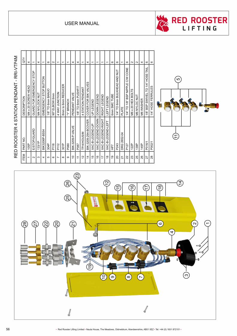
56
USER MANUAL
▪ Red Rooster Lifting Limited ▪ Nauta House, The Meadows, Oldmeldrum, Aberdeenshire, AB51 0EZ ▪ Tel: +44 (0) 1651 872101 ▪
12 14
1615 17 18
1
3
4
6
23
19
222 20 21
RE
D R
OO
STE
R 4
STA
TIO
N P
EN
DA
NT
- RR
I-VTP
4M
ITE
MPA
RT
NO
.D
ES
CR
IPTI
ON
QTY
110
5PM
4 x
20 S
CR
EW
HE
AD
4
2E
/STO
P/G
UA
RD
GU
AR
D F
OR
EM
ER
GE
NC
Y S
TOP
1
313
3/1P
M4
NY
LOC
K N
UT
4
4B
IK32
06P
-BS
54E
ME
RG
EN
CY
STO
P B
UTT
ON
1
530
4P1/
8” T
O 6
mm
BA
NJO
6
6P
118
90º E
LBO
W 6
mm
2
7P
112
4 W
AY J
UN
CTI
ON
1
830
1P8m
m to
6m
m R
ED
UC
ER
1
9P
080
“Y” B
RA
NC
H1
10B
IK-3
209-
P-V
ALV
EP
EN
DA
NT
VALV
E4
11P
087
1/8”
TO
6m
m P
US
HFI
T4
12TP
/4/H
OU
S/M
4 S
TATI
ON
PE
ND
AN
T1
14B
IK-3
209-
294-
BC
OV
ER
CO
VE
R F
OR
BIK
VA
LVE
S4
15X
AC
-B-L
EG
EN
D-U
PU
P LE
GE
ND
1
16X
AC
-B-L
EG
EN
D-D
OW
ND
OW
N L
EG
EN
D1
17X
AC
-B-L
EG
EN
D-R
IGH
TR
IGH
T LE
GE
ND
1
18X
AC
-B-L
EG
EN
D-L
EFT
LEFT
LE
GE
ND
1
19H
P7
6mm
SM
C T
UB
E6
20P
243
1/4”
TO
6m
m B
ULK
HE
AD
AN
D N
UT
6
21D
RG
265
2-04
PLA
TE1
22P
127
1/4”
TO
1/8
” BS
P N
IPP
LE C
/W C
ON
E6
2312
2PM
6 x
20 H
EX
BO
LTS
2
2513
9PM
6 N
YLO
C N
UT
2
2614
5PM
6 W
AS
HE
R4
27P
016/
11/
8” B
SP
SW
IVE
L TO
1/4
” HO
SE
TA
IL6
28P
002/
11/
4” H
OS
E F
ER
RU
LES
6
115
89 710
28 27
2526

57
USER MANUAL
▪ Red Rooster Lifting Limited ▪ Nauta House, The Meadows, Oldmeldrum, Aberdeenshire, AB51 0EZ ▪ Tel: +44 (0) 1651 872101 ▪

58
USER MANUAL
▪ Red Rooster Lifting Limited ▪ Nauta House, The Meadows, Oldmeldrum, Aberdeenshire, AB51 0EZ ▪ Tel: +44 (0) 1651 872101 ▪
V F A 5 3 20 - 03VALVE SERIES № OF
PORTS FUNCTION BODY TYPE PORT SIZE
Air Operated ValvePneumatic Pilot Spring Centreing 5 3 position closed center Body Ported 03 3/8”
HOW TO SELECT A VERSA VALVEEvery letter and digit in the product number has a significant meaning. The product numbers CJJ-4313 and CJJ-4503 shown below (CJJ-4313 which requires the C7M sub-base) indicate the following:
C J J - 4 3 1 3PNEUMATIC
SERVICEPILOT SPRINGCENTREING
PILOT SPRINGCENTERING
FOUR-WAY 1/4” NPT MANIFOLD MOUNTING EXPILOT
THREE POSITION
J - 4 3 1 3VALVEC
J
SERIESACTUATING DEVICES FUNCTIONAL
TYPE OF VALVE
VALVE PORT SIZE
BODY DETAILS SPOOL DETAILS
(FLOW PATTERNS)ON LEFT END OF VALVE
LOOKING AT INLETON RIGHT END OF VALVE LOOKING AT
INLET
V Series “V” ValvePneumatic service to 200 psi (14 bar)
J Pilot Spring Centreing (for 3 position pilot operated valves)
J Pilot Spring Centreing (for 3 position pilot operated valves)
4 Four-Way THREE-WAY VALVES3 Three Position All ports blocked in centre position.
3 1/4" NPT 1 MANIFOLD MOUNTING EXPILOT Body-ported for manifold mounting. This type of body is screw connected to a manifold that is connected to pressure lines and is used for mechanical, manual and Expilot type solenoid or pilot actuated valves.
HOW TO SELECT A MANIFOLD
C 7 M - 4 4 0MANIFOLD TYPE
VALVE SIZEVALVE TYPE
CYLINDER PORT SIZE
PORT TYPE
C7M 1/4” 4 Four-Way 4 3/8” 0 NPT
Every letter and digit in the product number has a significant meaning. The product number shown below (C7M-440 which works with the CJJ-4313 valve) indicates the following:
MANIFOLD TYPE FOUR-WAYVALVE
3/8” CYLINDER PORT
NPT PORT TYPE
C 7 M - 4 4 0
C J J - 4 5 0 3PNEUMATIC
SERVICEPILOT SPRINGCENTREING
PILOT SPRINGCENTERING
FOUR-WAY 1/4” NPT MANIFOLD MOUNTING EXPILOT
THREE POSITION
J - 4 5 0 3VALVEC
J
SERIESACTUATING DEVICES FUNCTIONAL
TYPE OF VALVE
VALVE PORT SIZE
BODY DETAILS SPOOL DETAILS
(FLOW PATTERNS)ON LEFT END OF VALVE
LOOKING AT INLETON RIGHT END OF VALVE LOOKING AT
INLET
V Series “V” ValvePneumatic service to 200 psi (14 bar)
J Pilot Spring Centreing (for 3 position pilot operated valves)
J Pilot Spring Centreing (for 3 position pilot operated valves)
4 Four-Way THREE-WAY VALVES3 Three Position All ports blocked in centre position.
5 1/2" NPT 0 SIDEPORTED-EXPILOT Body with integral, pipe threaded ports. This type of body is directly connected to pressure lines and is used for mechanical, manual nad EXPilot* type solenoid or pilot actuated valves.
The C7 is a four-way manifold mounted and body ported, two/three position (5/2 5/3) valve, with ¼” NPT ports standard and ISO G thread optional. The manifold mounted valves are designed to be mounted on a stacking style manifold and can be manual, pilot or electrically operated with a variety coil options, as well as the Plug-In feature. An optional Pre-Wired sub D connector can support up to 12 valves on a manifold.The body ported valves are of a universal flow design, solenoid, manual or pilot operated and can be mounted individually or side by side using #8 screws or on a 2 to 10 station rack mounted manifold (for more information on manual and pilot actuated valves see page 9).
Every letter and digit in the product number has a significant meaning. The product number VFA5320-03P shown below shows the following:
3 position closed centre : VFA5320-03P

59
USER MANUAL
▪ Red Rooster Lifting Limited ▪ Nauta House, The Meadows, Oldmeldrum, Aberdeenshire, AB51 0EZ ▪ Tel: +44 (0) 1651 872101 ▪
HOW TO SELECT A VERSA VALVEEvery letter and digit in the product number has a significant meaning. The product numbers CJJ-4313 and CJJ-4503 shown below (CJJ-4313 which requires the C7M sub-base) indicate the following:
C J J - 4 3 1 3PNEUMATIC
SERVICEPILOT SPRINGCENTREING
PILOT SPRINGCENTERING
FOUR-WAY 1/4” NPT MANIFOLD MOUNTING EXPILOT
THREE POSITION
J - 4 3 1 3VALVEC
J
SERIESACTUATING DEVICES FUNCTIONAL
TYPE OF VALVE
VALVE PORT SIZE
BODY DETAILS SPOOL DETAILS
(FLOW PATTERNS)ON LEFT END OF VALVE
LOOKING AT INLETON RIGHT END OF VALVE LOOKING AT
INLET
V Series “V” ValvePneumatic service to 200 psi (14 bar)
J Pilot Spring Centreing (for 3 position pilot operated valves)
J Pilot Spring Centreing (for 3 position pilot operated valves)
4 Four-Way THREE-WAY VALVES3 Three Position All ports blocked in centre position.
3 1/4" NPT 1 MANIFOLD MOUNTING EXPILOT Body-ported for manifold mounting. This type of body is screw connected to a manifold that is connected to pressure lines and is used for mechanical, manual and Expilot type solenoid or pilot actuated valves.
HOW TO SELECT A MANIFOLD
C 7 M - 4 4 0MANIFOLD TYPE
VALVE SIZEVALVE TYPE
CYLINDER PORT SIZE
PORT TYPE
C7M 1/4” 4 Four-Way 4 3/8” 0 NPT
Every letter and digit in the product number has a significant meaning. The product number shown below (C7M-440 which works with the CJJ-4313 valve) indicates the following:
MANIFOLD TYPE FOUR-WAYVALVE
3/8” CYLINDER PORT
NPT PORT TYPE
C 7 M - 4 4 0
C J J - 4 5 0 3PNEUMATIC
SERVICEPILOT SPRINGCENTREING
PILOT SPRINGCENTERING
FOUR-WAY 1/4” NPT MANIFOLD MOUNTING EXPILOT
THREE POSITION
J - 4 5 0 3VALVEC
J
SERIESACTUATING DEVICES FUNCTIONAL
TYPE OF VALVE
VALVE PORT SIZE
BODY DETAILS SPOOL DETAILS
(FLOW PATTERNS)ON LEFT END OF VALVE
LOOKING AT INLETON RIGHT END OF VALVE LOOKING AT
INLET
V Series “V” ValvePneumatic service to 200 psi (14 bar)
J Pilot Spring Centreing (for 3 position pilot operated valves)
J Pilot Spring Centreing (for 3 position pilot operated valves)
4 Four-Way THREE-WAY VALVES3 Three Position All ports blocked in centre position.
5 1/2" NPT 0 SIDEPORTED-EXPILOT Body with integral, pipe threaded ports. This type of body is directly connected to pressure lines and is used for mechanical, manual nad EXPilot* type solenoid or pilot actuated valves.
The C7 is a four-way manifold mounted and body ported, two/three position (5/2 5/3) valve, with ¼” NPT ports standard and ISO G thread optional. The manifold mounted valves are designed to be mounted on a stacking style manifold and can be manual, pilot or electrically operated with a variety coil options, as well as the Plug-In feature. An optional Pre-Wired sub D connector can support up to 12 valves on a manifold.The body ported valves are of a universal flow design, solenoid, manual or pilot operated and can be mounted individually or side by side using #8 screws or on a 2 to 10 station rack mounted manifold (for more information on manual and pilot actuated valves see page 9).
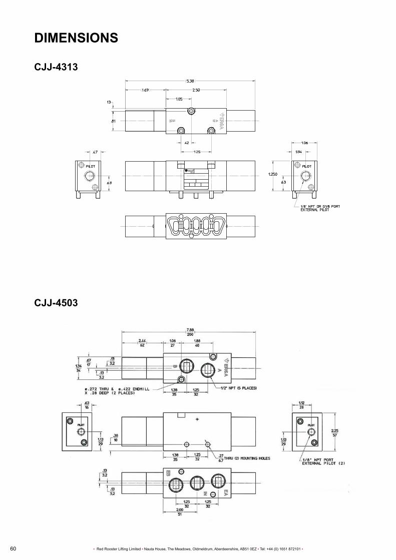
60
USER MANUAL
▪ Red Rooster Lifting Limited ▪ Nauta House, The Meadows, Oldmeldrum, Aberdeenshire, AB51 0EZ ▪ Tel: +44 (0) 1651 872101 ▪
Part No.:CJJ-4313 - 02/03/2012. visit http;//www.versa-valves.com/dlegal.html for terms on using this document.
DIMENSIONS
CJJ-4313
CJJ-4503

61
USER MANUAL
▪ Red Rooster Lifting Limited ▪ Nauta House, The Meadows, Oldmeldrum, Aberdeenshire, AB51 0EZ ▪ Tel: +44 (0) 1651 872101 ▪

62
USER MANUAL
▪ Red Rooster Lifting Limited ▪ Nauta House, The Meadows, Oldmeldrum, Aberdeenshire, AB51 0EZ ▪ Tel: +44 (0) 1651 872101 ▪

63
USER MANUAL
▪ Red Rooster Lifting Limited ▪ Nauta House, The Meadows, Oldmeldrum, Aberdeenshire, AB51 0EZ ▪ Tel: +44 (0) 1651 872101 ▪
ACCESSORIES

64
USER MANUAL
▪ Red Rooster Lifting Limited ▪ Nauta House, The Meadows, Oldmeldrum, Aberdeenshire, AB51 0EZ ▪ Tel: +44 (0) 1651 872101 ▪
ACCESSORIES
MAINS EMERGENCY STOP VALVES
ON TCR and TNC model hoists the mains valve can either be internal or mounted external to the hoist. As a mains emergency stop valve we usearangeof3/2normallyclosedvalvesonpendantcontrolhoists.Theserangefrom0.5”to1.5”dependingonthehoistcapacitybutwiththe latest hoists having the valves built into the hoist they are only required on cord conversion to pendant hoists on hoists manufactured before 2014.
Valvemodels:0.5”=VSA3135-04,0.75”=VSA3145-06,1”=VPA3165-10 ATEXversion0.75”=X773.32.11.1C,0.75”=VJJ4306/2B,1”=VJJ4703-2B
PILOT VALVE
These valves are used on TCR hoists where the pendant length is more than 10 metres long. The valves are opened by the control air from the pendant opening the valve allowing full pressure to open the hoist spool valve.
Valve model: SYJA712-01
DUMP VALVES
Onhoistsfittedwith1/4”airhoseinplaceoftubes,dumpvalvesarefittedtothecontrollinestoreduceoperatingdelays.
Valve model: DV/0.25
FILTER SILENCING - TYPE AMC
This ensures clean plant air and reduces noise levels.
In areas where you do not want the exhaust air / oil to go freely into the atmosphere we can either pipe the exhaust air away to another room, fitafiltersilencerunit,oracombinationofbothusingtheexhaustpipewithafiltersilencerontheendofthehose.
Thefilterremoves99.9%ofoilfromtheexhaustair. The noise level is also reduced by the silencer and also with the exhaust noise. Temperature range 5°C to 60°C. Theexhausthoseandfiltershouldbeatleastonesizelargerthantheincomingairsupplyhose. The exhaust cleaner must be mounted vertically. Iftheoildropleveldecreasesorafteraperiodof1yearthefilterelement.

65
USER MANUAL
▪ Red Rooster Lifting Limited ▪ Nauta House, The Meadows, Oldmeldrum, Aberdeenshire, AB51 0EZ ▪ Tel: +44 (0) 1651 872101 ▪
ACCESSORIES

66
USER MANUAL
▪ Red Rooster Lifting Limited ▪ Nauta House, The Meadows, Oldmeldrum, Aberdeenshire, AB51 0EZ ▪ Tel: +44 (0) 1651 872101 ▪
AIR SERVICE EQUIPMENT
An air set should be used with all Red Rooster hoists and trolleys. AIR SERVICE UNITS:
The correct size of air service unit for each hoist type is stated in the table on page 4. The air service unit must be installed with the lubricator unit downlinefromthefilterunit.Theunitshouldbeinstalledatthehoistinletportorwithineightmetresofinletport.(Sitingtheunitfurtherawayor well below the hoist will result in lubricant being deposited on the internal walls of the supply line and hence it will be necessary to increase the lubricantrateabovethelevelsspecified(seesection1.2)toensureadequatelubricationofthehoist.Theambienttemperaturerangeis -5°C to +60°C (with no freezing).
FILTER UNIT (WATER TRAP)
Manual drain units Asthenameimplies,theseunitsmustbedrainedbytheoperatorasthefilterbowlbecomesfullofwater.Thefrequencyofdrainingisentirely dependent upon the usage of the hoist and the moisture level of the air supply.
Incleanenvironmentse.g.laboratories,paintspraybooths,manualdrainfiltersareessentialtopreventcontamination.
Automatic drain units Theseunitsareautomaticallyself-purging.Whenthefilterbowlisfullitwillautomaticallydrainitself.Althoughveryconvenienttotheuser,the unit must be sited such that either the purged water is captured by a tray or it purges into an area away from personnel, equipment (particularly electrical equipment) and goods. If contamination from purged water is not a problem then automatic drain units should be selected.
Failuretofitanddrainthefilterwillresultinexcessivemoisturebeingcarriedintothehoistvalve,motorandbrakeactuatorresultingininternal corrosion and premature failure.
LUBRICATOR UNIT
There are two types of lubricator available.
Oil mist lubricator The preferred type, and essential where the lubricator must be sited some distance from the hoist. The unit produces atomised oil particles which remain in suspension in the air longer.
Droplet Lubricator Due to the larger particle size of the droplets, these may only be used where the lubricator is close to the coupled hoist.
Failuretofitalubricatorandmaintainthecorrectoilflowwillresultinrapidwearoftherotorvaneswithinthemotor,excessiveheatgenerationand failure of the air motor within a very short period. Keep the lubricator topped up with a light turbine oil. WORKING PRINCIPLE AND ADJUSTMENT
A portion of the air introduced from the IN side pressurises the lubricant inside the bowl. The remainder of the air passes through the needles 9,andflowstotheOUTside.Thepressuredifferentialbetweentheinsideofthebowlandtheinsideofthesightdome2,causesthelubricant inside the bowl into the oil passage 10 . The lubricant drips from the dripping tube 11 , and lubricate the OUT side. The amount of lubricant is adjusted by the needle 9 , on the front face. Turning the needle clockwise increases the amount of lubricant, and turning it counter clockwise until fully opened shuts off the lubricant. The needle on the side that is not used should be left fully opened.
DANGER
CAUTIONCAUTION
DANGERDANGER
9
Needle Section AA
A A OutIn
11
10
2

67
USER MANUAL
▪ Red Rooster Lifting Limited ▪ Nauta House, The Meadows, Oldmeldrum, Aberdeenshire, AB51 0EZ ▪ Tel: +44 (0) 1651 872101 ▪
AIR SERVICE EQUIPMENT
REGULATOR UNIT
Most compressors are supplied with a regulator on the ouput. However, where a number of different pneumatic tools are supplied from the same compressoritisgoodpracticetomaintainthesupplylineorremainatahigherpressureandtofitaregulatortothesupplyateachtool.
The operating pressures stated for the air hoist are the pressures required at the hoist inlet manifold. Subject to the type of airline, a pressure drop in the line between 0.1 and 0.35 bar (2 and 5 p.s.i) per 10 metres of line should be anticipated (as a result of the frictional resistance of the walls).
MOUNTING / ADJUSTMENT - WARNING
1. Set the regulator while verifying the displayed values of the inlet and outlet pressure gauges. Turning the regulator knob excessively can cause damage to the internal parts. 2. Do not use tools on the pressure regulator knob as this may cause damage. It must be operated manually.
MOUNTING / ADJUSTMENT - CAUTION
1. Be sure to unlock the knob before adjusting the pressure and lock it after setting the pressure. Failure to follow this procedure can causedamagetotheknobandtheoutletpressuremayfluctuate.
Pullthepressureregulatorknobuptounlock.(Youcanvisuallyverifythiswiththe‘orangemark’thatappearsinthegap.)
Push the pressure regulator knob down to lock. When the knob is not easily locked, turn it left and right a little and then push it. (Whentheknobislocked,the‘orangemark’,i.e.thegapwilldisappear.)
2. Pulsation will generate when the difference between the inlet and the outlet pressure is large. In this case, reduce the pressure difference between the inlet and the outlet. Please consult with SMC if pulsation problem is not resolved.
3. When the bowl is installed, install them so that the lock button lines up to the groove of the front (or the back) of the body to avoid dropping or damage of the bowl.
Lock button
Orange mark
Image for illustration purposes only

68
USER MANUAL
▪ Red Rooster Lifting Limited ▪ Nauta House, The Meadows, Oldmeldrum, Aberdeenshire, AB51 0EZ ▪ Tel: +44 (0) 1651 872101 ▪

69
LOG BOOK
▪ Red Rooster Lifting Limited ▪ Nauta House, The Meadows, Oldmeldrum, Aberdeenshire, AB51 0EZ ▪ Tel: +44 (0) 1651 872101 ▪
LOG BOOK

70
LOG BOOK
▪ Red Rooster Lifting Limited ▪ Nauta House, The Meadows, Oldmeldrum, Aberdeenshire, AB51 0EZ ▪ Tel: +44 (0) 1651 872101 ▪
PNEUMATIC HOIST AND TROLLEY INSPECTION REQUIREMENTS
Pneumatichoists,trolleysandoverheadcranesshouldbeinspectedasspecifiedinthe‘SupplyofMachinery(Safety)Regulations2008andThe Provision of Use of Powered Machinery (PUWER) S12306 sections 5 & 6 and the results recorded in the log book.
External inspection by a competent person every 12 months or as per the examination scheme. The Lifting Operations and Lifting Equipment Regulations S12306 - 1998. DAILY OR SHIFT INSPECTION
At the same time each day at the start of each working day of shift operator should carry out a basic inspection of the equipment, its operation and lubrication as required.
MONTHLY OR 3 MONTHLY CHECKS
Depending on the frequency of use and the working conditions, inspection and maintenance should be done at suitable intervals to ensure any deterioration of the equipment will be detected and remedied in good time.
ANNUAL INSPECTION
A competent person with the requisite knowledge of the equipment should carry out a full inspection of powered lifting equipment every 12 months or after any exceptional circumstances which could jeopardize the safety of the lifting equipment. A report should be issued and sent to the customer / employer.
DAILY HOIST AND TROLLEY INSPECTION REQUIREMENTS
The items listed below are intended as a guide for performing daily visual inspections of the components that have a direct bearing on the safety of the hoist and or trolley where the status may change with day to day use. The equipment items listed below do not necessarily need to be restricted to these items, but they should form the basis of the inspection.
OPERATING CONTROLS: Check for malfunction, excessive wear, broken or damaged components and control function labels. HOIST CHAIN: Check chain lubrication, twisted chains (multi fall blocks). AIR SET: Check oil level indicator. SAFETY CATCHES: Check operation and for damage. NOISE / OPERATION: Check for any unusual noise and speeds during function tests. HOIST OPERATION: Check the hoist starts and stops quickly.
EXTRA CHECKS FOR TROLLEY OPERATION: Check movement and control of the trolley (no load). TROLLEY MOVEMENT: Check the trolley moves smoothly along the beam.
PNEUMATIC HOIST AND TROLLEY MAINTENANCE REQUIREMENTS
TO BE CARRIED OUT MONTHLY OR THREE MONTHLY DEPENDING ON THE HOIST WORKING CONDITIONS
DAMAGE: External inspection of hoist for damage or wear. HOIST CHAIN: Check chain lubrication, twisted chains (multi fall blocks) and excessive wear or damaged chain links. (Light mineral oil). HOOKS: Check hooks swivel, hook opening and safety catch. AIRSET: Checkandfilluplubricatorbowlandadjustdroprateasrequired. FITTINGS/HOSES:Checkallair-linefittingaresecureandtherearenoairleaks. BOLTS: Check security of bolts, chain collector and chain anchor. AIR MOTOR: Check air motor and silencers - replace as required. OPERATION: Function test hoists running speed and control operation without load and then check lifting a load of around 50% of SWL to check brake operation and controls when loaded. LIMIT SWITCHES: Check operation of upper and lower limits at slow speed.
EXTRA CHECKS FOR TROLLEY
RUNWAYBEAM: Checkthebeamissmoothandflatwithoutobstructionandthattheendstopsareinplaceandsecure. DIVEPINION: Checkdrivepinionandwheelsarefittingcorrectlyandnotworn,greaseifrequired. ADJUSTMENT: Checkflangeadjustment,antitiltrollersetting,loadbarnuts-adjustortightenifrequired, AIRLINES: Checksecurityofcontrollinesandsupplyhosesandfittings. OPERATION: Function test over the complete range of travel. SUPPLY HOSES: Check air lines are supported and the weight is not hanging from the air set. TROLLEY CHAIN: Check geared trolley hand chain and drive.
When detecting any abnormality during inspection due to erroneous use, instruct the operator and user for correct use of the chain hoist.

71
LOG BOOK
▪ Red Rooster Lifting Limited ▪ Nauta House, The Meadows, Oldmeldrum, Aberdeenshire, AB51 0EZ ▪ Tel: +44 (0) 1651 872101 ▪
DA
ILY
VIS
UA
L IN
SP
EC
TIO
N R
EQ
UIR
EM
EN
TS
MO
NTH
:Y
EA
R:
DAY
12
34
56
78
910
1112
1314
1516
1718
1920
2122
2324
2526
2728
2930
31
AIR
HO
IST
CH
EC
KS
HO
OK
SW
IVE
L
AIR
LE
AK
S
AIR
SE
T LU
BR
ICAT
ION
SA
FETY
CAT
CH
ES
NO
ISE
/ O
PE
RAT
ION
PE
ND
AN
T O
PE
RAT
ION
/ E
-STO
P
CH
AIN
LU
BR
ICAT
ION
CH
AIN
NU
T TW
ISTE
D
SU
PP
LY H
OS
E
CH
AIN
CO
LLE
CTO
R
TRO
LLE
Y C
HE
CK
S
OP
ER
ATIO
N /
NO
ISE
FES
TOO
N S
YS
TEM
S
MO
VE
ME
NT
(IF F
ITTE
D)
OP
ER
ATO
R’S
NA
ME
1. 2. 3. 4. CO
MM
EN
TSIN
ITIA
LSD
ATE

72
LOG BOOK
▪ Red Rooster Lifting Limited ▪ Nauta House, The Meadows, Oldmeldrum, Aberdeenshire, AB51 0EZ ▪ Tel: +44 (0) 1651 872101 ▪
MAINTENANCE CHECKS
TO BE CARRIED OUT MONTHLY IN PRODUCTION OPERATIONS WHERE HEAVILY USED OR IN HARSH WORKING CONDITIONS.TO BE CARRIED OUT THREE MONTHLY WHEN THE HOIST IS ONLY USED OCCASIONALLY.
PLEASE CONTACT RED ROOSTER TO CONFIRM IF MONTHLY OR THREE MONTHLY MAINTENANCE CHECKS ARE REQUIRED IF YOU ARE NOT SURE.
MONTHLY / 3 MONTHLY CHECKS CARRIED OUT AS PER MANUAL NAME DATE

HeadOffice: T: +44 (0) 1651 872101Nauta House Oldmeldrum E: [email protected] Meadows Aberdeenshire, AB51 0EZ W: www.redroosterlifting.com Depot:Unit 26 Kelvin Way T: +44 (0) 121 525 4162Kelvin Way Trading Estate West Bromwich, B70 7TW