air defense missile detonation delay control based on fpga/ · pdf fileair defense missile...
TRANSCRIPT

Air defense missile detonation delay control Based on FPGA/DSP
Lian-zheng Zhang, Pan-long Wu and Xin-yu Zhang Department of Automation
Nanjing University of Science and Technology No. 200, Xiao Ling Wei Street, Nanjing 210094
PEOPLE’S REPUBLIC OF CHINA [email protected], [email protected], [email protected]
Abstract: - This paper presents the hardware design of a real time tracking system based on DSP/FPGA regarding the research and air defense missile detonation delay. It is a new trend of missile technology using guidance integrated fuze (GIF) technology to realize optimal burst delay control algorithm. The optimal burst delay control algorithm includes the estimation of time-to-go and miss distance. The paper studied the application of second order debiased converted measurement Kalman (SDCMKF) filer in parameters estimation of burst delay control. In this tracking system, the FPGA is used as a floating point co-processor of the fixed point DSP, and the large amount of calculation of the second order debiased converted measurement Kalman Filter (SDCMKF) algorithm is realized in FPGA. DSP is in charge of the scheduling of the total tracking algorithm and the control of the data stream, which resolves the problem of the concurrency and real time in the realization of the single DSP scheme. The designed tracking system ensures the accuracy of the data processing as well. Simulation results indicate that the application of this algorithm improved the estimation accuracy of burst delay control. The estimation error reduces gradually and tends to be stable with the distance between target and missile shortened. Key-Words: - Target tracking, air defense missile detonation delay, burst delay control, SDCMKF, coprocessor, FPGA, DSP. 1 Introduction To improve the weapon system effectiveness in encounter with future air threat likely to have a high level of agility and sophisticated countermeasure, performance requirements of the fuze become more and more stringent, the guidance integrated fuzing (GIF) is an emerging trend in missile technology [1-2]. GIF is a kind of fuze technology based on the new concept and new theory of fuze, which aims for getting more encountering information about missile and target and improving the efficiency of matching of fuze with warhead. The speed of the final engagement and the difficulty in actually hitting maneuvering target require the use of proximity fuzes that are capable of detecting the target, detonating the warhead at the proper time to inflict maximum damage and extending the kill envelope. With increase in warhead directionality, target speed and decrease in target size, performance requirements of the fuze become more and more stringent. The GIF technology will be widely used and developed in the future [3].
The complexity of detonation delay control algorithm lies in the three-dimensional space rendezvous of missile and target, and is mainly reflected in the following two aspects: (1) The
encounter rendezvous conditions are complex; (2) The independent localization capability of fuze is not good [1].
In the real system, the radar measurements in a spherical coordinate system, whereas, the target’s state equation is generally established in the Cartesian coordinate system, the measurement equation in spherical coordinates to Cartesian coordinates is a nonlinear equation. State and measurement equations are often not in the same coordinate system of linear equations. General method is the use of extended Kalman filtering (EKF). Another method is to use the debiased converted measurement Kalman filter [2-3] (DCMKF). The standard DCMKF is commonly derived from a first order Taylor expansion of the state dynamics and measurement model. The truncation of Taylor series covers the bias of converted measurement error, which may lead to linearization error and divergence because of dealing with maneuvering targets as a type of nonlinear actual systems. However this problem can be avoided to some extent by using the second order term of Taylor series. In this paper, the second order debiased converted measurement Kalman (SDCM-KF) filer is applied to calculate the time-to-go and miss distance of burst delay control.
WSEAS TRANSACTIONS on SYSTEMS Lian-Zheng Zhang, Pan-Long Wu, Xin-Yu Zhang
E-ISSN: 2224-2678 202 Issue 4, Volume 12, April 2013

In the traditional software system design, SDCMKF is usually realized by digital signal processor (DSP), which would be restricted by the serial instruction stream due to the complex computations of SDCMKF and unable to meet the high-speed real-time signal processing needs. However, using the hardware parallel architecture feature of field programmable gate array (FPGA) to realize floating point of SDCMKF can resolve the problem of high precision and real time[18, 21-23].
This paper based on FPGA realization of floating point SDCMKF can resolve the problem of high precision and real time in air defense missile detonation delay system. Compared Matlab and Quartus Ⅱsimulation data , both of the simulation results are consistent, this ensure that the computational accuracy. This paper mainly studies the use of FPGA to realize floating point SDCMKF and air defense missile detonation delay effective method. 2 General system design In this paper, we adopt DSP TMS320VC5509A chip as core processor of the radar target tracking system. This fixed point DSP is responsible for the scheduling of the whole tracking algorithm and the control of data stream. The FPGA EP3C120F484C8N chip is adopted as floating point co-processor of fixed point DSP. DSP receives radar measurements values then transmits to FPGA. FPGA informs DSP to retrieve the filtered system state values when one frame data is processed. 2.1 Hardware design of the system
DSP FPGA
SDRAM
FLASH
SD UART EEPROM
POWER
Fig.1 The structure diagram of system hardware
design.
The structure diagram of system hardware design is shown in Fig.1. This system is composed of DSP subsystem and FPGA subsystem. DSP subsystem consists of DSP, FLASH, synchronous dynamic random access memory (SDRAM), secure digital (SD) card and some peripheral interface circuits, FLASH is used to store program. SDRAM is used to
buffer pre-filtered and post-filtered data. SD card is used to store both filtered and unfiltered data. FPGA subsystem consists of FPGA and electrically erasable programmable read-only memory (EEPROM). FPGA is used to realize the complicated DCMKF algorithm, EEPROM is used to store FPGA program.
Fig.2 shows the hardware connection diagram between DSP and FPGA. External memory interface (EMIF) connects DSP and FPGA. Wherein, CE is chip electing signal, AOE is asynchronous output enable signal, AWE is asynchronous writing electing signal, ARE is asynchronous reading enable signal, INT[4 : 0] is interrupt enable signal, D[7:0] is data bus signal and A[7:0] is address bus signal. Wherein, IO(D[7:0]) is data bus signal , IO( INT ) is interrupt enable signal.
ARE
CE
AWE
AOE
D[7:0]
A[7:0]
INT[4:0]
FPGA
IO(ARE)
IO(CE)
IO(AWE)
IO(AOE)
IO(D[7:0])
IO(A[7:0])
IO(INT[4:0])
DSP Fig.2 The hardware connection diagram between DSP
and FPGA.
Fig.3 shows the sequence diagram of writing operation between DSP and FPGA. AOE and ARE are set high when writing.
Fig.3 The sequence diagram of writing operation
between DSP and FPGA. 2.2 Software design of the system In software design of the system, intensive data and highly repetitive algorithm are processed by FPGA, while low repetitive algorithm is processed by DSP. In this radar target tracking system, initial value of SDCMKF needs to be calculated only once. Therefore, the initial value of SDCMKF is calculated by DSP then transmits to FPGA. However, the
WSEAS TRANSACTIONS on SYSTEMS Lian-Zheng Zhang, Pan-Long Wu, Xin-Yu Zhang
E-ISSN: 2224-2678 203 Issue 4, Volume 12, April 2013
subsequent each frame data needs to be filtered and consumes a large number of processing time. Therefore, we choose FPGA to complete SDCMKF algorithm. Fig.4 shows the software block diagram of the radar target tracking system. The first three frames data of correctly received from radar are calculated for initial values of SDCMKF. After the system receives correctly the fourth frame data, DSP transmits the calculated initial values and the measurement value to FPGA for SDCMKF filtering. An interrupt signal is transmitted to DSP to retrieve the filtered target state values after FPGA processing each frame data.
Data frames is greater than or equal to 3
Calculation the initial value of SDCMKF
Receive data frames greater than 4
Transmission initial value and the fourth
measured data to FPGA
Transfer measurement data to the FPGA
DSP reads the data from FPGA
DSP receives interrupt signal from FPGA
Y
N
Y
N
Y
DSP receives radar data
Fig.4 Software design of the system
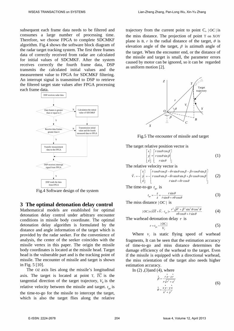
3 The optimal detonation delay control Mathematical models are established for optimal detonation delay control under arbitrary encounter conditions in missile body coordinate. The optimal detonation delay algorithm is formulated by the distance and angle information of the target which is provided by the radar seeker. For the convenience of analysis, the center of the seeker coincides with the missile vertex in this paper. The origin the missile body coordinates is located at the missile head. Target head is the vulnerable part and is the tracking point of missile. The encounter of missile and target is shown in Fig. 5 [10].
The OZ axis lies along the missile’s longitudinal axis. The target is located at point T, TC
is the tangential direction of the target trajectory, RV is the relative velocity between the missile and target. got is the time-to-go for the missile to intercept the target, which is also the target flies along the relative
trajectory from the current point to point C, | |OC is the miss distance. The projection of point T on XOY plane is B, r is the radial distance of the target, θ is elevation angle of the target, β is azimuth angle of the target. When the encounter end, or the distance of the missile and target is small, the parameter errors caused by motor can be ignored, so it can be regarded as uniform motion [2].
Target trajectory
Z
X
rVr
O
T
θ
CB
β
Y
Fig.5 The encounter of missile and target
The target relative position vector is
cos cos= cos sin
sin
θ βθ βθ
x ry rz r
(1)
The relative velocity vector is cos cos sin cos cos sincos sin sin sin cos cos
sin cos
θ β θ θ β β θ βθ β θ θ β β θ β
θ θ θ
− − = − = − − + +
r
x r r rV y r r r
z r r (2)
The time-to-go got is
sinsin cos
θθ θ θ
= − =+
goz rtz r r
(3)
The miss distance | |OC is 2 2 2 2 2sin cos| | | |
cos sinθ β θ θθ θ θ+
= + ⋅ =+
r gorOC OT V t
r r (4)
The warhead detonation delay τ is | |τ = −go
f
OCtV
(5)
Where fV is static flying speed of warhead fragments, It can be seen that the estimation accuracy of time-to-go and miss distance determines the damage efficiency of the warhead to the target. Even if the missile is equipped with a directional warhead, the miss orientation of the target also needs higher estimation accuracy.
In (2) ,(3)and (4), where
2 2
2 2
r z z rr r z
x y y xx y
β
θ
• ••
• ••
−=
+
−=
+
(6)
WSEAS TRANSACTIONS on SYSTEMS Lian-Zheng Zhang, Pan-Long Wu, Xin-Yu Zhang
E-ISSN: 2224-2678 204 Issue 4, Volume 12, April 2013

4 SDCMKF principle 4.1 Analysis of Converted Measurement Errors The measured target position ( the distance mr , the azimuth mβ and the elevation mθ ) is defined with respect to the true position ( the true distance r , the true azimuth β and the true elevation θ ) as [4]
θ θ θ
β β β
= + = + = +
m
m
m
r r r (7)
where the errors in distance r , azimuth β and elevation θ are assumed to be independent with zero mean and standard deviation rσ , βσ and θσ
respectively. These polar measurements are converted to the Cartesian coordinate measurements[14-16]
cos cos= = cos sin
sin
θ βθ β
θ
m m m m
m m m m
m m m
x rZ y r
z r (8)
From (8), we know that the converted measurements are correlated and nonlinear with respect to the polar measurements ( mr , mβ and mθ ).
If the measurement errors of r , β and θ are small and target distance is close, errors statistic approximations obtained in Cartesian coordinates are accurate. These approximations are obtained by taking the first-order terms of a Taylor series expansion for the (8) to approximate the Cartesian coordinate errors as
cos cos cos sin θ β θ θ β β θ β− −
x = r rsin cos r (9) θ β θ θ β β θ β− +
y = rcos sin rsin sin rcos cos (10) θ θ θ= + z rsin rcos (11)
Note that the approximation transformation errors are unbiased. However, the standard transformations are biased. The truncated high-order terms can significantly affect tracking accuracy if the cross-distance error is large. To reduce the linearization errors caused by truncated high-order terms of Taylor series expansion, we take the second-order terms of Taylor series expansion for the (8) to obtain the higher approximations of the Cartesian coordinate errors.
2 21 ( )2
+
θ β θ β θ θ β θ β
θ θ β β θ β θβ θ β β θ β
− + − +
− − −
x = rcos cos rsin cos rcos cos
rsin cos rcos sin rsin sin rcos sin(12)
2 21 ( )2
θ β θ β θ θ β θ β
θ θ β β θ β θβ θ β β θ β
− + − +
− + − +
y = rcos sin rsin sin rcos sin
rsin sin rcos cos rsin cos rcos cos(13)
212
θ θ θ θ θ θ θ= + + −
z rsin rcos r cos rsin (14)
Where the mean of the errors (12), (13) and (14) does not equal zero, the second-order Taylor series expansion approximations for the transformation are
biased, which partially accounts for the bias of polar-to-Cartesian transformation measurement.
From (12), (13) and (14) the average true deviation aµ and average true covariance aR of converted measurement are described as
( | , , )( | , , ) [ , , ]( | , , )
β θµ β θ µ µ µ
β θ
= =
x y z Ta a a a
E x rE y rE z r
(15)
=
xx xy xza a ayx yy yz
a a a azx zy zza a a
R R RR R R R
R R R
(16)
where 22
2 21 ( )(1 ) cos cos2 2 2
βθθ β
σσµ σ σ θ β= − + − −xa m m mr ,
222 21 ( )(1 ) cos sin
2 2 2βθ
θ β
σσµ σ σ θ β= − + − −ya m m mr ,
221 (1 ) sin
2 2θ
θσµ σ θ= − −z
a m mr ,
2 2 2 2 2 2 2 2 2 2 2 31 2
442 2 2 2 2 2 2 2 2 24
1 2 3
442
4
( ) ( )4 4 4
( )2 2 4
( )2 2
θ β θ θ β β
βθθ β θ β
βθ
αα ασ σ σ σ σ σ σ σ
σσ ασ σ σ σ δ σ σ δ σ σ δ
σσ σ δ
= + + + +
+ + + + + +
+ +
xxa m r m r m
m m r r r r
r
R r r r
r r ,
2 2 2 2 2 2 2 2 2 2 22 1 4
442 2 2 2 2 2 2 2 2 23
2 1 4
442
3
( ) ( )4 4 4
( )2 2 4
( )2 2
θ β θ θ β β
βθθ β θ β
βθ
α α ασ σ σ σ σ σ σ σ
σσ ασ σ σ σ δ σ σ δ σ σ δ
σσ σ δ
= + + + +
+ + + + + +
+ +
yya m r m r m
m m r r r r
r
R r r r
r r ,
2 2 2 4 2
6 2 4 2
2 2 2 4 2
6 2 4 2
4 2 2 2 2 2 4
1 5(4 )sin sin2 2
1 5 (( ) ) sin sin2 21 5 (4 )cos cos2 21 5 (( ) ) cos cos2 21 1 1 1 ( ) ( 22 2 2 2
θ θ
θ θ θ
θ θ
θ θ θ
θ θ θ θ
σ σ σ σ σ θ θ
σ σ σ θ θ
σ σ σ σ σ θ θ
σ σ σ θ θ
σ σ σ σ σ σ σ
= − − −
− + −
+ − −
+ + −
+ + + + +
zza r r r m m
m m m
r r r m m
m m m
m r r
R
r
r
r 2 )r
,
( )4 2 2 2 2 2 2 2
4 2 2
1(( ) ) 1 2 sin cos sin2
1 ( ) sin cos sin2
θ θ θ θ β
θ θ
σ σ σ σ σ σ σ θ θ β
σ σ σ θ θ β
= − + − − −
+ −
yza m r r m m m
r m m m
R r,
( )4 2 2 2 2 2 2 2
4 2 2
1(( ) ) 1 2 sin cos cos2
1 ( ) sin cos cos2
θ θ θ θ β
θ θ
σ σ σ σ σ σ σ θ θ β
σ σ σ θ θ β
= − + − − −
+ −
xza m r r m m m
r m m m
R r,
4 44 42 2 2 2 2 2 21 2
2 2 2 2 2 2 2 2 2 2 34
442 2 2 2 2 2
442 2 2 2 2
(( ) ) ( )2 2 4 2 2 4
( ) (( ) )4 4
1 (( ) ( ) )4 2 21 (( )4 2 2
β βθ θβ β β
θ θ β θ θ β θ
βθβ θ θ β
βθβ θ θ β
σ σσ σγ γσ σ σ σ σ σ
γγσ σ σ σ σ σ σ σ σ
σσ σ σ σ σ σ σ
σσ σ σ σ σ
= + − + − + + −
+ − + − +
− + − − −
− + − + − +
xya m r r r
r m r
r r
m
R r
r
r 2 2 2 2 2 )θ βσ σ σ σ σ+ −r r r
,
2 21
2 2
1 (1 2 )os 2 (1 2 )cos 2
(1 2 2 )cos 2 cos 2β θ
θ β
α σ β σ θ
σ σ θ β
= − − − −
+ − −
m m
m m
WSEAS TRANSACTIONS on SYSTEMS Lian-Zheng Zhang, Pan-Long Wu, Xin-Yu Zhang
E-ISSN: 2224-2678 205 Issue 4, Volume 12, April 2013

2 22
2 2
1 (1 2 )os 2 (1 2 )cos 2
(1 2 2 )cos 2 cos 2β θ
θ β
α σ β σ θ
σ σ θ β
= + − − −
+ − −
m m
m m
,
2 23
2 2
1 (1 2 )os 2 (1 2 )cos 2
(1 2 2 )cos 2 cos 2β θ
θ β
α σ β σ θ
σ σ θ β
= + − + −
− − −
m m
m m
,
2 24
2 2
1 (1 2 )os 2 (1 2 )cos 2
(1 2 2 )cos 2 cos 2β θ
θ β
α σ β σ θ
σ σ θ β
= − − + −
+ − −
m m
m m
,
1
2
3
4
1 cos 2 cos 2 cos 2 cos 2
1 cos 2 cos 2 cos 2 cos 2
1 cos 2 cos 2 cos 2 cos 2
1 cos 2 cos 2 cos 2 cos 2
δ β θ θ β
δ β θ θ β
δ β θ θ β
δ β θ θ β
= − − +
= + − −
= − + −
= + + +
m m m m
m m m m
m m m m
m m m m
,
2 2 21
22 2 2
3
4
1 (1 2 )sin 2 (1 2 2 )cos 2 sin 21 sin 2 cos 2 sin 2
1 (1 2 )sin 2 (1 2 2 )cos 2 sin 21 sin 2 cos 2 sin 2
β θ β
β θ β
γ σ β σ σ θ β
γ β θ β
γ σ β σ σ θ β
γ β θ β
= + − + − −
= + +
= + − − − −
= + −
m m m
m m m
m m m
m m m
.
When measurement in the polar coordinate is converted to be in the Cartesian coordinate, the measurement is modified as
cos coscos sinsin
θ βµ θ β µ
θ
= − = −
m m m
c a m m m a
m m
rZ Z r
r (17)
4.2 Target tracking model This paper selects Singer acceleration model as target dynamic model [12]. State equation of the system is
1k k k kX X W+ = Φ + Γ (18) Measurement equation is
k k k kZ H X V= + (19) where, [ , , , , , , , , ]T
k k k k k k k k k kX x y z x y z x y z= serves as state vector of the system, including target’s position, velocity and acceleration in X , Y and Z direction, respectively. Φ is system state transition matrix, kΓ is noise gain matrix, kW is system process noise matrix,
kZ is the system measurement vector, kH is measurement matrix, kV is measurement noise vector.
17
28
39
47
58
69-
-
-
1 0 0 0 0 0 00 1 0 0 0 0 00 0 1 0 0 0 00 0 0 1 0 0 0 00 0 0 0 1 0 0 00 0 0 0 0 1 0 00 0 0 0 0 0 0 0
0 0 0 0 0 0 0 00 0 0 0 0 0 0 0
x
y
z
T
T
T
TT
T
e
ee
α
α
α
φφ
φφ
φφ
Φ =
(20)
Where 2
17 ( 1 ) /αφ α α−= − + xTx xT e , 2
28 ( 1 ) /αφ α α−= − + yTy yT e ,
239 ( 1 ) /αφ α α−= − + zT
z zT e , 47 (1 ) /αφ α−= − xTxe , 58 (1 ) /αφ α−= − yT
ye ,
69 (1 ) /αφ α−= − zTze . [ ]1 2 3
TkΓ = Γ Γ Γ (21)
where
2 2 3
2 2 31
2 2 3
1 ( 2)
1 ( 2)
1 ( 2)
x
y
z
Tx x x x
Ty y y y
Tz z z z
T e T
diag T e T
T e T
α
α
α
γ α α α
γ α α α
γ α α α
−
−
−
− − + Γ = − − + − − +
,
2
22
2
( 1)
( 1)( 1)
x
y
z
Tx x x
Ty y
Tz z
T e
diag T eT e
α
α
α
γ α α
γ α αγ α α
−
−
−
+ − Γ = + − + −
,
3
(1 )
(1 )(1 )
x
y
z
Tx x
Ty y
Tz z
e
diag ee
α
α
α
γ α
γ αγ α
−
−
−
− Γ = − −
,
2max max 0( ( )(1 4 ( ) ) / 3), , ,i sqrt a i P i P i x y zγ = + − = .
where, xγ , yγ , zγ , x y zα α α α= = = describes the first-order forming filter parameter of the attacking target’s acceleration in the Cartesian coordinate [5]. T is system measurement period.
1 0 0 0 0 0 0 0 00 1 0 0 0 0 0 0 00 0 1 0 0 0 0 0 0
=
kH (22)
4.3 SDCMKF algorithm The block diagram of SDCMKF algorithm is shown in Fig.6.
k+1->k
0 , 1P k = 0 , 1X k =
, 1 , 1 1 , 1 , 1 1 , 1T T
k k k k k k k k k k k kP P Q− − − − − − −= Φ Φ +Γ Γ
, 1[ ]k k k k kP I K H P −= −
1, 1 , 1[ ]T T
k k k k k k k k kK P H H P H R −− −= +
, 1 , 1 1ˆ ˆ
k k k k kX X− − −= Φ
, 1 , 1ˆ ˆ ˆ[ ]k k k k k k k k kX X K z H Xµ− −= + − −
1kQ −
kR
k kz µ
Fig.6 Block diagram of DCMKF algorithm
The calculation steps of SDCMKF is given as 1) Calculating the initial value 0X and initial covariance matrix 0P , and assuming
0fX X= , 0fP P= . 2) Predicting state vector
p fX X= Φ (23) 3) Calculating covariance matrix of the predicted states
T Tp fP P Q= Φ Φ + Γ Γ (24)
4) Calculating the mean deviation aµ and covariance aR of the converted measurement according to equation (15) and (16). 5) Calculating gain matrix
1( )T Tk p p kK P H HP H R −= + (25)
6) Updating state vector
WSEAS TRANSACTIONS on SYSTEMS Lian-Zheng Zhang, Pan-Long Wu, Xin-Yu Zhang
E-ISSN: 2224-2678 206 Issue 4, Volume 12, April 2013
( )f p k k k pX X K Z HXµ= + − − (26) 7) Updating covariance matrix
( )f k pP I K H P= − (27) 8) Repeating step 2) to 6) for recursive computation 5 Realization of hardware of SDCMKF algorithm 5.1 Structural hierarchy design
Top-level module of DCMKF
Trigonometri
cmodul
e
GainMatrixmodule
StatePredict
ionmodul
e
FilterErrorCovariancemodul
e
State update module FIFOmodule
Floating
Pointoperat
ionmodul
e
GainMatri
xCalcul
atemodul
e
Prediction
ErrorCovaria
ncemodule
AverageTrueConvarian
cevalue
Floating
Pointoperation
module
Floating
Pointoperation
module
Floating
Pointoperation
module
FloatingPoint
operation
module
Floating
Pointoperati
onmodule
Coordinate
Transformati
onmodule
Average
TrueDeviation
module
Residuals
module
State update
Calculatemodule
Floating
Pointoperati
onmodule
Floating
Pointoperati
onmodule
Floating
Pointoperati
onmodule
Floating
Pointoperati
onmodule
FIFOmodule
2
FIFOmodule
1
Counter
module
Floating
Pointoperati
onmodule
Time-to go andMiss
distancemodule
Floating
Pointoperati
onmodule
Fig.7 Structural hierarchy design of SDCMKF and air defense missile detonation delay based on FPGA
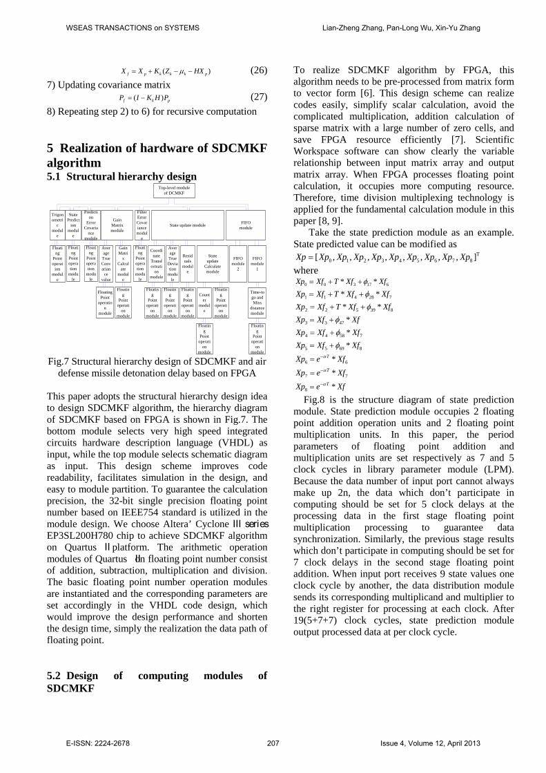
This paper adopts the structural hierarchy design idea to design SDCMKF algorithm, the hierarchy diagram of SDCMKF based on FPGA is shown in Fig.7. The bottom module selects very high speed integrated circuits hardware description language (VHDL) as input, while the top module selects schematic diagram as input. This design scheme improves code readability, facilitates simulation in the design, and easy to module partition. To guarantee the calculation precision, the 32-bit single precision floating point number based on IEEE754 standard is utilized in the module design. We choose Altera’ Cyclone Ⅲ series EP3SL200H780 chip to achieve SDCMKF algorithm on Quartus Ⅱ platform. The arithmetic operation modules of Quartus Ⅱon floating point number consist of addition, subtraction, multiplication and division. The basic floating point number operation modules are instantiated and the corresponding parameters are set accordingly in the VHDL code design, which would improve the design performance and shorten the design time, simply the realization the data path of floating point. 5.2 Design of computing modules of SDCMKF
To realize SDCMKF algorithm by FPGA, this algorithm needs to be pre-processed from matrix form to vector form [6]. This design scheme can realize codes easily, simplify scalar calculation, avoid the complicated multiplication, addition calculation of sparse matrix with a large number of zero cells, and save FPGA resource efficiently [7]. Scientific Workspace software can show clearly the variable relationship between input matrix array and output matrix array. When FPGA processes floating point calculation, it occupies more computing resource. Therefore, time division multiplexing technology is applied for the fundamental calculation module in this paper [8, 9].
Take the state prediction module as an example. State predicted value can be modified as
T0 1 2 3 4 5 6 7 8[ , , , , , , , , ]Xp Xp Xp Xp Xp Xp Xp Xp Xp Xp=
where 0 0 3 17 6* *Xp Xf T Xf Xfφ= + + 1 1 4 28 7* *Xp Xf T Xf Xfφ= + + 2 2 5 39 8* *Xp Xf T Xf Xfφ= + + 3 3 47 *Xp Xf Xfφ= + 4 4 58 7*Xp Xf Xfφ= + 5 5 69 8*Xp Xf Xfφ= + 6 6*TXp e Xfα−= 7 7*TXp e Xfα−= 8 *TXp e Xfα−= Fig.8 is the structure diagram of state prediction
module. State prediction module occupies 2 floating point addition operation units and 2 floating point multiplication units. In this paper, the period parameters of floating point addition and multiplication units are set respectively as 7 and 5 clock cycles in library parameter module (LPM). Because the data number of input port cannot always make up 2n, the data which don’t participate in computing should be set for 5 clock delays at the processing data in the first stage floating point multiplication processing to guarantee data synchronization. Similarly, the previous stage results which don’t participate in computing should be set for 7 clock delays in the second stage floating point addition. When input port receives 9 state values one clock cycle by another, the data distribution module sends its corresponding multiplicand and multiplier to the right register for processing at each clock. After 19(5+7+7) clock cycles, state prediction module output processed data at per clock cycle.
WSEAS TRANSACTIONS on SYSTEMS Lian-Zheng Zhang, Pan-Long Wu, Xin-Yu Zhang
E-ISSN: 2224-2678 207 Issue 4, Volume 12, April 2013

5
7CLK
CLK
CLK
CLK
CLK
CLK
Computing moduleData distributio
module
CLK
CLK
CLK
CLK
CLK
fXpX
Fig.8 Structure diagram of state prediction module
Fig.9 is the Top level schematic diagram of
prediction module in step one.
Fig.9 Schematic diagram of predictable module in
step one
where Xf is the input data port of state prediction module, namely the state estimate before a moment. clk is the clock signal, rst is the reset signal, clk_enable_Xf is the enable signal of output data of receiving former module, clk_enable_Xp is the enable signal of receiving data next operation module, Xp is output data port of state prediction module, the design idea of input and output port of other operation module is similar, here not repeated introduction. 5.2.1 Counter module When the encounter end, or the distance of the missile and target is small, the parameter errors caused by motor can be ignored, so it can be regarded as uniform motion. So this stage design is a key point and difficulty, here we can design a counter, when the counter counts to 78, that is, measuring the distance to the target is not higher than 350 meters, it can be treated as uniform motion.
Fig.10 is the Top level schematic diagram of counter module.
Fig.10 Schematic diagram of counter module.
where clk_enable_Xf is the enable signal of output data of receiving former module, jishu is output data port of counter module, clk_enable_jishu is the enable
signal of counter module, and initial value of jishu is zero, and it has began to count until the clk_enable_Xf from low level became into a high level. The clk_enable_jishu has always been low level until it became high level when counter counted to 78.
5.2.2 Design of air defense missile detonation delay
Fig.11 Schematic diagram of air defense missile
detonation delay.
Fig.11 is the top level schematic diagram of air defense missile detonation delay module. Air defense missile detonation delay module consists of sinn_cosn, epslnn_betan_dot, r_v_Xf and tgo_OC module. sinn_cosn is the angle (Angle of pitch and azimuth) of sin and con after filtering module, epslnn_betan_dot is the angle (Angle of pitch and azimuth) derivative after filtering module, r_v_Xf is the distance, speed and the direction of the position vector after filtering module, tgo_OC is the time to go and miss distance module.
Where clk_enable2 is the reading enable signal of FIFO memory module(lpm_fifo1 module is used to temporarily store state update value), QXf is output data port of lpm_fifo1 module, here it is used as input data port of r_v_Xf module, clk_enable_r_v_Xf is the output enable signal of r_v_Xf module, r_v_Xf is output data port of r_v_Xf module.
6 Simulation and results Fig.12 shows the hardware circuit board , this subsystem is composed of DSP, FPGA, SDRAM, FLASH, SD and other components. The power supply of circuit board of DSP subsystem is DC 5V. The power supply of the circuit board of FPGA subsystem is 24V DC. Firstly, the power convert chip converts the DC 24V to DC 5V, then supply to the DSP subsystem through the connection. In the FPGA subsystem, DC 5V is converted to 3.3V, 2.5V and 1.2V respectively.
WSEAS TRANSACTIONS on SYSTEMS Lian-Zheng Zhang, Pan-Long Wu, Xin-Yu Zhang
E-ISSN: 2224-2678 208 Issue 4, Volume 12, April 2013

Fig.12 Hardware circuit board
In this section, a simulation scenario is presented
to track a highly maneuvering target. The target has different acceleration at different time segment. The parameters of target are given as follows. The initial conditions of the target is (954 ,697 ,302 )m m m for position and ( 634 / , 465 / , 200 / )m s m s m s− − − for velocity. The sampling rate is 10t ms= . The segments are defined as follows. 1st segment, (0 250)t ms= − , constant velocity flight with acceleration
2 2(5 / , 2 / ,0)m s m s . 2nd segment, (251 500)t ms= − , accelerated flight with acceleration
2 2( 5 / , 2 / ,0)m s m s− − . 3rd segment, (501 750)t ms= − , accelerated flight with acceleration 0 . In Singer module, the variance of the measured distance r , elevation θ and azimuth β are 25r mσ = ,
2 5 25 10 radθσ−= × , 2 5 25 10 radβσ
−= × , The variance of the process noise for Singer module (2,2,2)Q diag= , the probability of biggest maneuverable acceleration
max 0.5P = , the probability of non-maneuverable 0 0.5P = . The target’s first-order forming filter
parameters of acceleration in Cartesian coordinate are 2.041xγ = , 1.291yγ = , 0.2887zγ = , 0.1α = . In the
process of simulation, firstly, the seeker’s measurement information are filtered using the SDCMKF, then the time-to-go and miss distance are estimated. The SDCMKF algorithm is realized respectively in FPGA and Matlab platform using the same measurements. Fig.13 is after and before filtering of X. Fig.14 is after and before filtering of Y. Fig.15 is after and before filtering of Z. Fig.16 is after and before filtering of Time-to-go. Fig.17 is after and before filtering of miss distance . It is easily seen from
the 5 figures above that the SDCMKF is capable of denoising and smoothing for target position. Fig.13, Fig.14, Fig.15, Fig.16 and Fig.17 show the results of FPGA are consistent with the simulated results by Matlab. The high precision proves the correctness of this design scheme.
0 500 1000 15000
100
200
300
400
500
600
700
800
900
1000
t/ms
x/m
realSDCMKF(MATLAB)SDCMKF(Quartus Ⅱ)
Fig.13 Comparision in axis X
0 500 1000 15000
100
200
300
400
500
600
700
800
t/ms
y/m
realSDCMKF(MATLAB)SDCMKF(Quartus Ⅱ)
Fig.14 Comparision in axis Y
0 500 1000 15000
50
100
150
200
250
300
350
t/ms
z/m
realSDCMKF(MATLAB)SDCMKF(Quartus Ⅱ)
Fig.15 Comparision in axis Z
WSEAS TRANSACTIONS on SYSTEMS Lian-Zheng Zhang, Pan-Long Wu, Xin-Yu Zhang
E-ISSN: 2224-2678 209 Issue 4, Volume 12, April 2013

0 100 200 300 400 500 600 700 8000
100
200
300
400
500
600
700
800
t/ms
Tim
e-to
-go/
ms
realSDCMKF(MATLAB)SDCMKF(Quartus Ⅱ)
Fig.16 Comparison in axis time-to-go
0 100 200 300 400 500 600 700 8000
200
400
600
800
1000
1200
t/ms
Mis
s di
stan
ce/m
realSDCMKF(MATLAB)SDCMKF(Quartus Ⅱ)
Fig.17 Comparision in axis miss distance
In [4], the second-order debiased converted
measurement Kalman filter ( SDCMKF ) algorithm is proposed to reduce the effect of the linearization approximation error of the conventional EKF and CMKF algorithms in the 3D tracking system. A numerical simulation example is given, which indicates that the SCMKF effectively reduces the nonlinear effect by the polar measurement and improves the accuracy and the convergence of the tracking system.
From the timing simulation in Quartus Ⅱ, we can see that experimental results prove the designed SDCMKF algorithm based on FPGA spends 455 clock periods to complete one filter process. If the clock periods is 40ns, a filtering cycle is 18.2us. This time fully satisfies the real time requirement in target tracking system. The radar tracking performance gained in our design scheme includes two to three orders of magnitude higher speed than single DSP design scheme.
7 Conclusion
In this paper, mathematical models are established for optimal detonation delay control under arbitrary encounter conditions in missile coordinate and a new SDCM tracking algorithm using radar measurements is proposed for optimal detonation delay control. In the radar target tracking system, the tracking precision and real time are highly required. SDCMKF algorithm includes a great deal of matrix arithmetic, such as matrix addition, matrix subtraction, matrix multiplication and inverse. The computational time for calculating SDCMKF algorithm in software is too long to meet the real time of target tracking. In this paper, the FPGA is used as a floating point co-processor of fixed point DSP. This software and hardware reasonable design scheme can solve the concurrency and speed problems and guarantee the tracking precision. Therefore, it is an effective approach to complete target tracking algorithm. The design based on FPGA has large degree flexibility for programming, updates codes at any time, and largely reduces the research cost. This research results have been successfully applied to a certain type of short-range defence radar. Acknowledgement This work is partially supported by the National Nature Science Foundation of China (NO. 61104196), “Zijin star” Research Funding(NO. AB41381). References: [1] Chopper, K., H. Jaeger, L. Stephens, et al,
Guidance integrated predictive fuzing design, Proc. American Control Conference, Chicago, IL, June 1992.
[2] Chopper, K., H. Harold, L. Stephens, et al, Guidance integrated fuzing analysis and simulation, Proc. Conference on Control Applications, Dayton, OH, Sept. 1992.
[3] Yan Han-xin, Jiang Chun-lan, Research on terminal efficiency of air-air missile against hypersonic weapons with GIF ( Guidance Integrated Fuzing), 2010 2nd International Asia Conference on Informatics in Control, Automation and Robotics, 262-265.
[4] Chen H., Tan J.B., Target tracking based on second-order converted measurement Kalman filter, Opto-Electronic Engineering, Vol.35, No. 4, 2008,pp.6-11.
[5] Bar-Shalom Y, Li X R, Kirubarajan T, Estimation with Applications to Tracking and Navigation: Therory, Algorithm and Software, New York: Wiley, 2001.
[6] Dr S M Shalinie, Associate Menber. Design and Analysis of Customized Embedded Kalman
WSEAS TRANSACTIONS on SYSTEMS Lian-Zheng Zhang, Pan-Long Wu, Xin-Yu Zhang
E-ISSN: 2224-2678 210 Issue 4, Volume 12, April 2013

Filter. IE(I) Journal-CP, Vol.88, NO.5 2007, pp.39-42.
[7] Neri F. Cooperative Evolutive Concept Learning: An Empirical Study. WSEAS Transaction on Information Science and Applications, Vol.2, No.5, 2005, pp.559-563.
[8] Abbas Bigdeli, Morteza Biglari-Abhari, Zoran Salcic, and Yat Tin Lai. A New Pipelined Systolic Array-Based Architecture for Matrix Inversion in FPGAs with Kalman Filter Case Study. EURASIP Journal on Applied Signal Processing, Vol.2006, Article ID 89186, 2006, pp.1-12.
[9] Ventzas, D. A 4-bit Quantized Skip Algorithm Software Correlator for Microcomputer Systems. IASTED Symposium on Measuremen, Signal Processing and Control, MECO'86, Taormina, Italy, IASTED.
[10] Zhuang Z.H, Tu J.P., Wang H.B., Prediction of time-to-go during missile-target encounter, Journal of Astronautics, Vol.23, No.5, 2002, pp.32-37.
[11] Pan-Long Wu,Bao-Bao Wang,Cun-Hui Ji, Design and Realization of Short Range Defence Radar Target Tracking System Based on DSPFPGA, WSEAS Transactions on System. Vol.10, No.11, 2011, pp.379-380.
[12] ROBERT A. SINGER. Estimating optimal tracking filter performance for manned manoeuvring targets. IEEE Transactions on Aerospace and Electronic Systems, Vol.6, No.4, 1970, pp.473-483.
[13] Wu P.L., Wang B.B., Ji C.H., Design and realization of short range defence radar target tracking system based on DSP/FPGA, WSEAS Transactions on System, Vol.10, No.11, 2011, pp.376-386.
[14] Farina Alfonso, Ristic Branko, Benvenuti Dario. Tracking a Ballisitic Traget: Comparision of Several Nonlinear Filters. IEEE Transactions on Aerospace and Electronic Systems, Vol.38, No.3, 2002, pp.854-867.
[15] YU Yihua, CHENG Qian-sheng. Particle filters for maneuvering target tracking problem. Signal Processing, Vol.86, 2006, pp.195-203.
[16] Hsieh Chien-Shu. General Two-Stage Extended Kalman Filters. IEEE Transactions on Automatic Control, Vol.48, No.2, 2003, 289-293.
[17] CHEN Gang, GUO Li. The FPGA Implementation of Kalman Filter. Proceedings of the 5th WSEAS Int. Conf. on Signal Processing, 2005, pp.61-65.
[18] C.R. Lee, Z. Salcic. High-performance FPGA-based Implementation of Kalman Filter.
Mircroprocessors and Microsystems, Vol.21, No. 4, 1997, pp.257-265.
[19] ZHOU Hong-bo, GENG Bo-ying. Converted Measurements Kalman Filter Algorithm for Target Tracking. Journal of System Simulation, Vol.20, No.3, 2008, pp.682-688.
[20] HE Ming-ke, WANG Zheng-ming, ZHU Ju-bo. Debiased Converted Measurement KF for Radar Target Tracking. Journal of National University of defence technology, Vol.24, No.5, 2002, pp.57-60.
[21] ZHOU Ning-ning, CHEN Yan-li, LI Ai-qun. Design and implementation of floating point calculator based on FPGA technology. Computer Engineer and Design, Vol.26, No.6, 2005, pp.1578-1581.
[22] ZHONG Sheng, HOU Chao-huan, YANG Chang-an. Optimized design of matrix multiplier based on FPGA. Electronic Measurement Technology, Vol.31, No.2, 2008, pp.95-102.
[23] CHEN Gang, GUO Li. The FPGA Implementation of Kalman Filter. Proceedings of the 5th WSEAS Int. Conf. on Signal Processing, 2005, pp.61-65.
WSEAS TRANSACTIONS on SYSTEMS Lian-Zheng Zhang, Pan-Long Wu, Xin-Yu Zhang
E-ISSN: 2224-2678 211 Issue 4, Volume 12, April 2013