air-cooled modular chiller
TRANSCRIPT

Air-cooled
Modular Chiller
Technical Manual
Models
NCMH-30SN
NCMH-65SN
NCMH-130SN
Air-cooled Modular Chiller Technical Manual Content
I
Preface .........................................................................................1
Introduction............................................................................................................. 1
Part 1. System Outline .................................................................2
1. Products Line-up ............................................................................................ 2
2. External Appearance ................................................................................... 3
3. Features ............................................................................................................ 4
4. Pipe Connection Drawing ......................................................................... 15
5. Refrigeration system drawing ................................................................ 18
6. Wiring Diagrams......................................................................................... 200
7. Networking Communication wiring diagram ................................... 23
8. Control system ............................................................................................. 24
Part 2. Trouble Shooting ............................................................26
1. Malfunction & Protection Codes ........................................................... 26
2. Troubles and Solutions ............................................................................. 28
Part 3. Installation ...................................................................300
1. Transportation and Foundation Installation ................................... 300
2. Water System Installation........................................................................ 36
3. Installation of water system pipeline ............................................... 400
4. Wiring Installation ....................................................................................... 49
5. Trial Operation ............................................................................................ 522
Part 4. Maintenance...................................................................55
1. For Maintenance .......................................................................................... 55
2. Periodical check .......................................................................................... 58
Part 5. Wired Controller .............................................................59
Appendix...................................................................................611
1. Accessories ................................................................................................. 611
2. Temperature-Resistance Characteristic Sheet ............................ 622
Content

Air-cooled Modular Chiller Technical Manual Preface
1
Preface
Introduction
Air-cooled modular chiller is a kind of central air-conditioning unit which adopts air as the cooling
(or heating) source and water as cooling (or heating) heat exchange medium. As a sort of
integrated equipment, it no needs cooling tower, cooling water pump, boiler and corresponding
auxiliary parts for the condenser, which makes system more simple to install and convenient to
maintenance, saves energy and installation space, thus it is very suitable for the regions that are
short of water.
NEOCLIMA Air-cooled modular chillers are designed and produced on the basement of
sufficiently absorbing the top technology in AC areas, adopting high quality self-control
components which are made by world famous producers. Moreover, after improvement, units
can run more efficiently and more stably. 30kW module adopts independent unit frame, 65kW
module consists of two units and 130kW module consists of three, and also several modules can
be formed into a integrated unit by connecting each module’s inlet & outlet pipeline in parallel.
The whole unit consists of 2-16 modules and the max capacity can be achieved to 2080kW.
NEOCLIMA Air-cooled modular chillers can be widely applied to civilian projects and industrial
projects, such as office, hotel, villa, restaurant, hospital, factory, etc.. It is a wise choice for the
regions where water is insufficient or there are strict limits on noise level and surroundings.
AIR-COOLED MODULAR CHILLER

Air-cooled Modular Chiller Technical Manual System Outline
2
Part 1.
System Outline
1. Products Line-up
No Model Refrigerant Net dimension Net weight
Power supply (L×W×H) (unit: mm) (kg)
1 NCMH-30SN R410A 1160×900×2090 320 380V/3ph/50Hz
2 NCMH-65SN R410A 2000×900×2090 570 380V/3ph/50Hz
3 NCMH-130SN R410A 2000×1700×2090 1100 380V/3ph/50Hz

Air-Cooled Modular Chiller Technical Manual System Outline
3
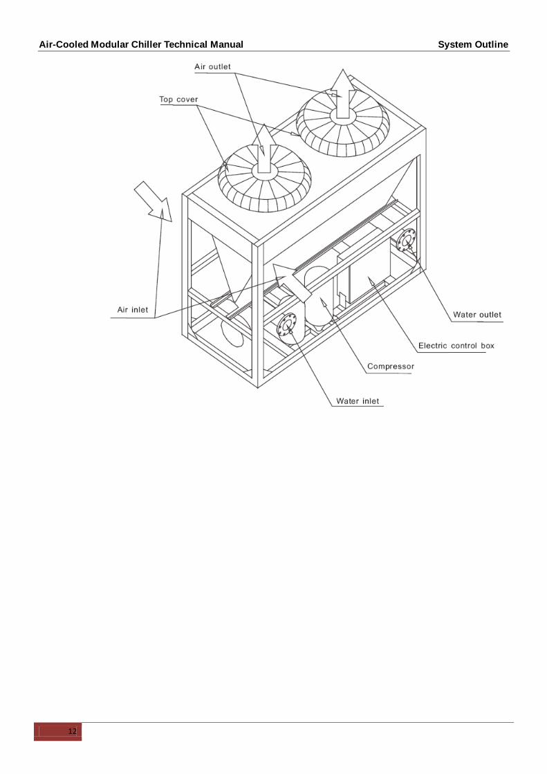
2. External Appearance
30kW 65kW
130kW

Air-Cooled Modular Chiller Technical Manual System Outline
4
3. Features
3.1 Modular design, flexible combination, more convenient for installation and transportation.
The unit adopts modular design, which can make more units connect together. The unit can combine 16
separate modules (30, 65, 130module). Meanwhile every separate module can operate as main unit, also
each module can be a slave unit with modules combination, more convenient for design and installation.
3.2 The maximum combination of the system consists of 1 main unit and 15 slave units.
3.3 Chilled water outlet temperature adjustable.
Chilled water outlet temperature can be adjusted by wired controller according to customer’s demand.
In cooling mode, the adjustable range from 7℃-25℃.
3.4 Easy connection between main unit and slave units.
3.5 Compact structure, no need cooling tower, which reducing installation cost.
3.6 Strong micro-computer intelligent control and monitor function.
3.7 System will be more reliable with new type efficient heat exchanger
Evaporator adopts tube-in-shell heat exchanger, higher reliability and efficiency, lower requirement of the
water quality.
65KW 65kW 1040KW

Air-Cooled Modular Chiller Technical Manual System Outline
5
3.8 Environmental care
Both R22 and ecological refrigerant R410A for choice meet different requirement.
Chlorine-free and environmental friendly refrigerant, zero ozone depletion potential.
High density refrigerant, therefore, less refrigerant required.
Leak-tight refrigerant circuit, Brazed refrigerant connections for increased leak-tightness.
3.9 Economical operation
New design adopts electronic expansion valve precise refrigerant control in wider range. Electronic expansion
valve allows operation at lower condensing pressure, adjustment can be made fast linear response, making
the system more stable output, the indoor temperature more uniform, and enhance human comfortable.
3.10 Back up function
When unit is failure
If master unit fails, all the units will stop.
If one slave unit fails, this unit will stop but the others will keep running.
When the master unit fails, any of the slave one can be set as the master unit by manual setting.
When unit is under protection
If master unit’s protection occurs, this system will stop.
If slave unit’s protection occurs, this unit will stop but the others will keep running.

Air-Cooled Modular Chiller Technical Manual System Outline
6
3.11 Applicable temperature range
Mode Ambient temperature range Water inlet temperature range
Cooling 10˚C ~48˚C 7˚C ~25˚C (12˚C is default)
Heating -10˚C ~21˚C 30˚C ~55˚C (40˚C is default)
Chilled outlet water temperature can be adjusted by wire controller according to customer’s demand.
3.12 Capacity Lineup
Model Mode Compressor
quantity Refrigerant
Refrigeration
system
Electrical
controller no.
Maximum
combinations
NCMH-30SN Cooling & Heating 1 R410A 1 1 16
NCMH-65SN Cooling & Heating 2 R410A 2 1 16
NCMH-130SN Cooling & Heating 4 R410A 4 1 16
-15˚C
Ambient temperature range
-10˚C -5˚C 0˚C 5˚C 10˚C 15˚C 20˚C 25˚C 30˚C 35˚C 40˚C 45˚C 50˚C
Cooling range 10˚C 48˚C
Inlet water temperature range
7˚C 25˚C 30˚C 55˚C
7˚C 25˚C Heating range Cooling range 30˚C 55˚C
Heating range -10˚C 21˚C

Air-Cooled Modular Chiller Technical Manual System Outline
7
3.13 Specification
R410A/50Hz
Model NCMH-30SN NCMH-65SN NCMH-130SN
Cooling Capacity kW 30 65 130
Btu/h 8.5 18.5 37
Heating Capacity kW 32 69 140
Power supply V/Ph/Hz 380V/3Ph/50Hz 380V/3Ph/50Hz 380V/3Ph/50Hz
Power supply Manual switch 100 150 250 250
Fuse 50 100 200 200
Compressor
Type Scroll Scroll Scroll
Brand Copeland Copeland Copeland
Model ZP144KCE-TFD-522 ZP144KCE-TFD-522 ZP144KCE-TFD-522
Quantity Pieces 1 2 4
Power input
Cooling kW 11.1 22 44
Cooling rated current A 19 38 78
Heating kW 10.8 21.3 43
Heating rated current A 18 37 76
Max. Input consumption kW 16 28 56
Max. Current A 29 51 102
Refrigerant
Type R410A R410A R410A
Refrigerant control EXV+ capillary throttle EXV+ capillary throttle EXV+ capillary throttle
Weight kg 7.0 7.0×2 7.5×4
Condenser (Air
side)
Air side heat-exchanger type Finned coil pipe type Finned coil pipe type Finned coil pipe type
Quantity of fan motor Pieces 1 2 4
Air flow volume 103m
3/h 12 24 48
Fan motor model YDK550-6S01 YDK550-6S01 YDK550-6S01
Fan motor rated current A 4.2 4.2 4.2
Fan motor input kW 0.911 0.911 0.911
Evaporator
(Water side)
Water side heat-exchanger type shell and tube shell and tube shell and tube
Water resistance loss kPa 30 30 40
Water inlet/outlet pipeline
inside normal diameter mm DN40 DN100 DN65
Water flow volume m3/h 5.16
11.18 22.36
Max. Pressure MPa 1.1/2.75 1.1/2.75 1.1/2.75
Water pipe connection type flange connection flange connection flange connection
Dimension Net(W×H×D) mm 1160×2090×900 2000×2090×900 2000×2090×1700
Packing size(W×H×D) mm 1240×2250×950 2080×2250×950 2080×2250×1740
Weight Net weight kg 320 570 1100
Gross weight kg 330 600 1120
Connection Power wiring mm2×No 16mm2×3+10mm2×2 16mm2×3+10mm2×2 25mm2×3+10mm2×2

Air-Cooled Modular Chiller Technical Manual System Outline
8
wiring Signal wiring mm2×No (0.5~1)mm2×2 (0.5~1)mm2×2 (0.5~1)mm2×2
Control type wired controller wired controller wired controller
Safety protection device
Power supply protection (lack of phase, phase sequence, frequency, voltage)
Chilled water pump overload protection
Chiller water shortage protection
Water outlet temp. protection
Compressor discharge temp. protection
Compressor low pressure protection
Compressor high pressure protection
Sensor malfunction protection.
Compressor current input protection
Fin temp. (ambient temp.) protection
Anti-frozen protection
Sound level(semi-anechoic ) dB(A) 62 65 68
Operation water
temp.
cooling ℃ 7-25 7-25 7-25
heating ℃ 30-55 30-55 30-55
Ambient temp
cooling ℃ 10-48 10-48 10-48
heating ℃ -10-21 -10-21 -10-21
Remarks: Specifications are based on the following conditions:
Cooling : chilled water inlet/outlet: 12˚C / 7˚C, and outdoor ambient temp. of 35°C DB.
Heating : warm water inlet/outlet: 40˚C / 45˚C, and outdoor ambient temp. 7˚C DB/6°CWB.
Water side fouling factor: 0.086m2˚C /kW.

Air-Cooled Modular Chiller Technical Manual System Outline
9
3.14 Electric Characteristics
Model Outdoor Unit Application Power Supply Compressor OFM
Hz VOL Ph Min. Max. TOCA MFA LRA RLA Qty KW FLA Qty
NCMH-30SN 50 380 3 342 418 31 50 107 19 1 550 5.06 1
NCMH-65SN 50 380 3 342 418 53 100 107 19 2 550 5.06 2
NCMH-130SN 50 380 3 342 418 105 200 107 19 4 550 5.06 4
Remark:
TOCA: Total Over-current Amps. (A)
MFA: Max. Fuse Amps. (A)
LRA: Locked Rotor Amps. (A)
RLA: Rated Load Amps. (A)
OFM: Outdoor Fan Motor.
FLA: Full Load Amps. (A)
KW: Rated Motor Input (KW)
Voltage vibration between phases: <2%.

Air-Cooled Modular Chiller Technical Manual System Outline
10
3.15 Outlook drawing
30kW: (NCMH-30SN)

Air-Cooled Modular Chiller Technical Manual System Outline
11
65kW(NCMH-65SN)
Air-Cooled Modular Chiller Technical Manual System Outline
12

Air-Cooled Modular Chiller Technical Manual System Outline
13
130kW(NCMH-130SN)

Air-Cooled Modular Chiller Technical Manual System Outline
14

Air-Cooled Modular Chiller Technical Manual System Outline
15
4. Pipe Connection Drawing
4.1 30kW
The table below describes the symbols.
Symbol Symbol explanation Symbol Symbol explanation
Stop valve
Y-shaped filter
Pressure gauge
Thermometer
Water flow switch
Circulating pump
Gate valve
Check valve
Flexible joint
Automatic discharge valve

Air-Cooled Modular Chiller Technical Manual System Outline
16
4.2 65kW
The table below describes the symbols.
Symbol Symbol explanation Symbol Symbol explanation
Stop valve
Y-shaped filter
Pressure gauge
Thermometer
Water flow switch
Circulating pump
Gate valve
Check valve
Flexible joint
Automatic discharge valve

Air-Cooled Modular Chiller Technical Manual System Outline
17
4.3 130kW
The table below describes the symbols.
Symbol Symbol explanation Symbol Symbol explanation
Stop valve
Y-shaped filter
Pressure gauge
Thermometer
Water flow switch
Circulating pump
Gate valve
Check valve
Flexible joint
Automatic discharge valve

Air-Cooled Modular Chiller Technical Manual System Outline
18
5. Refrigeration system drawing
5.1 30kW
Each module has two compressors with one A/C system, one shell and tube evaporate for two systems.
Compressor
lo. pressure cylinder
Fan
Capillary
EXV
4-Way valve
Dry type evaporator
Flow direction
5.2 65kW
Each module has two compressors with two separate A/C systems, one shell and tube evaporate for two
systems.
2# Compressor
2# lo. pressure cylinder
1# 4-Way valve
1#Fan
EXV
Capillary
EXV
Capillary
2# Fan
2# 4-Way valve
1# Compressor
1# lo. pressure cylinder
Dry type evaporator
Condenser
Flow direction

Air-Cooled Modular Chiller Technical Manual System Outline
19
5.3 130kW
Each module has four compressors with four separate A/C system, one tube-in-shell evaporate for four
systems.
2# Compressor
2# lo. pressure cylinder
1# 4-Way valve
1# Fan
EXV
Capillary
EXV
Capillary
2# Fan
2# 4-Way valve
1# Compressor
1# lo. pressure cylinder
Condenser
4# Compressor
4# lo. pressure cylinder
3# 4-Way valve
3# Fan
EXV
Capillary
EXV
Capillary
4# Fan
4# 4-Way valve
3# Compressor
3# lo. pressure cylinder
Dry type evaporator
Condenser
Flow direction

Air-Cooled Modular Chiller Technical Manual System Outline
20
6. Wiring Diagrams
6.1 30kW
Air-Cooled Modular Chiller Technical Manual System Outline
21
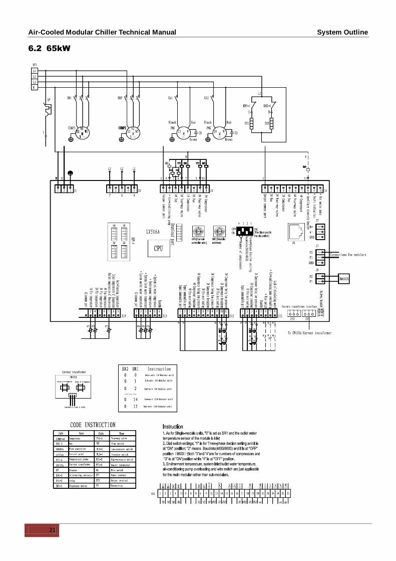
6.2 65kW
Air-Cooled Modular Chiller Technical Manual System Outline
22
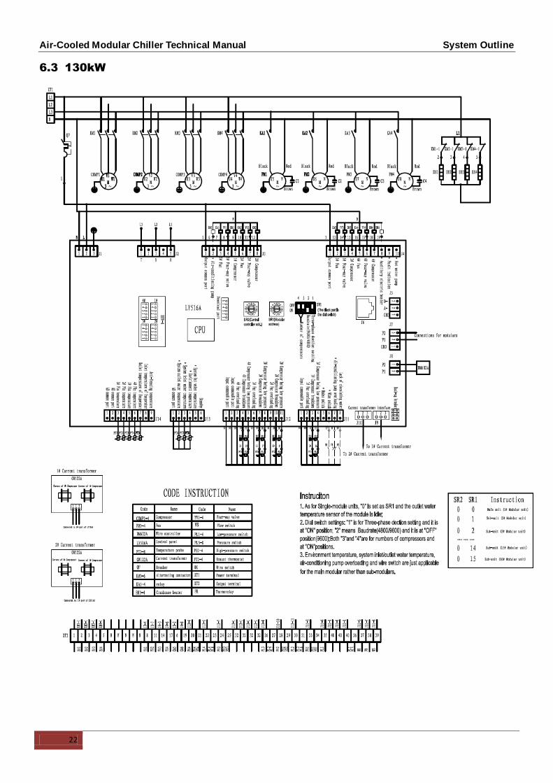
6.3 130kW

Air-Cooled Modular Chiller Technical Manual System Outline
23
7. Networking Communication wiring diagram
Remark:
The number of modules in each refrigeranting system is not more than 16.
The specification of the signal line is the two-core RVV in 2*0.75mm2.

Air-Cooled Modular Chiller Technical Manual System Outline
24
8. Control system

Air-Cooled Modular Chiller Technical Manual System Outline
25

Air-cooled Modular Chiller Technical Manual Trouble Shooting
26
Part 2.
Trouble Shooting
1. Malfunction & Protection Codes

Air-Cooled Modular Chiller Technical Manual Trouble Shooting
27

Air-cooled Modular Chiller Technical Manual Trouble Shooting
28
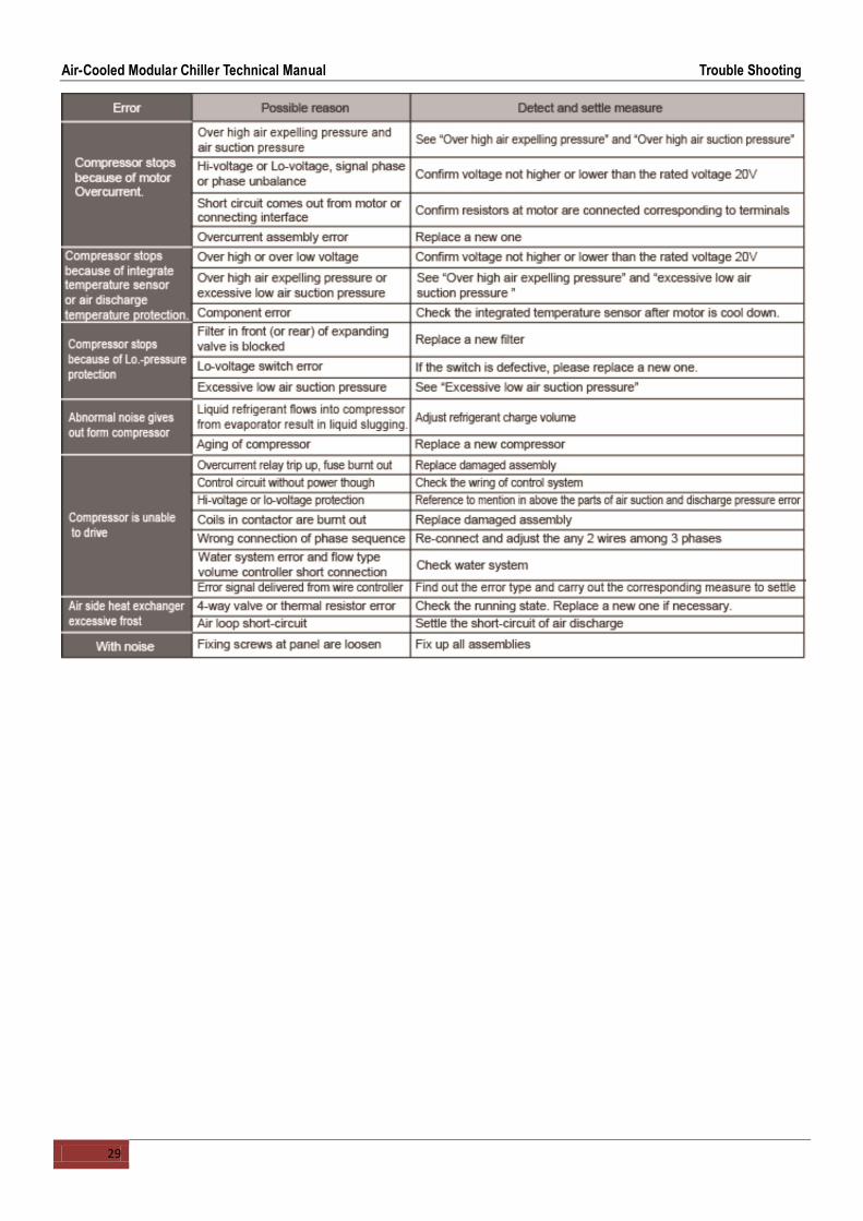
2. Troubles and Solutions
Air-Cooled Modular Chiller Technical Manual Trouble Shooting
29

Air-cooled Modular Chiller Technical Manual Installation
30
Part 3. Installation
1. Transportation and Foundation Installation
1.1 Transportation
The angle of inclination should not be more than 15º when carrying the unit, to avoid over turn of the unit.
1.1.1 Rolling handling: several rolling rods of the same size are placed under the base of the unit, and the
length of each rod must be more than the outer frame of the base and suitable for balancing of the unit.
1.1.2 Lifting: the strength lifting rope (belt) can bear should be 4 times the weight of the unit. Check the lifting
hook and ensure that it is firmly attached to the unit, and the lifting angle should be more than 60º. To
avoid damages to the unit, the contact position of the unit and lifting rope should be provided with an at
least 50mm thick wood block, cloth or hard paper. Any person is not allowed to stand below the unit
when lifting it.

Air-Cooled Modular Chiller Technical Manual Installation
31

Air-cooled Modular Chiller Technical Manual Installation
32
1.2 Installation space
1.2.1 Requirements of arrangement space of the unit
1) To ensure adequate airflow entering the condenser, the influence of descending airflow caused by the
high-rise buildings around upon the unit should be taken into account when installing the unit.
2) If the unit is installed where the flowing speed of air is high, such as on the exposed roof, the measures
including sunk fence and Persian blinds can be taken, to prevent the turbulent flow from disturbing the air
entering the unit. If the unit needs to be provided with sunk fence, the height of the latter should not be more
than that of the former; if Persian blinds are required, the total loss of static pressure should be less than the
static pressure outside the fan. The space between the unit and sunk fence or Persian blinds should also meet
the requirement of the minimum installation space of the unit.
3) If the unit needs to operate in winter, and the installation site may be covered by snow, the unit should be
located higher than the snow surface, to ensure that air flows through the coils smoothly.
Input of airflowInput of airflow
E
A
B
D
C
Input of airflow
Input of airflow
E
Input of airflowInput of airflow
NCMH-30SN
NCMH-65SN

Air-cooled Modular Chiller Technical Manual Installation
33
Input of airflow
Input of airflow
AB
DC
Input of airflowInput of airflow
E
The recommend space parameter
Module Installation space (mm)
A B C D E
30kW, 65kW, 130kW ≥1500 ≥2000 ≥1500 ≥2000 ≥8000
1.2.2 Space requirements for parallel installation of multiple modular units
To avoid back flow of the air in the condenser and operational faults of the unit, the parallel installation of
multiple modular units can follow the direction A and D as shown in the figure above, the spaces between the
unit and the obstacle are given in the figure above, and the space between adjacent modular units should not
be less than 300mm; the installation can also follow the direction B and C as shown in the figure above, the
spaces between the unit and the obstacle are given in the figure above, and the space between adjacent
modular units should not be less than 600mm; the installation can also follow the direction combination of A
and D, and B and C, the spaces between the unit and the obstacle are given in the figure above, the space
between adjacent modular units in the direction A and D should not be less than 300mm, and the space
between adjacent modular units in the direction B and C should not be less than 600mm.
If the spaces mentioned above cannot be met, the air passing from the unit to the coils may be restricted, or
back flow of air discharge may occur, and the performance of the unit may be affected, or the unit may fail to
operate.
1.3 Installation Foundation
The unit should be located on the horizontal foundation, the ground floor or the roof which can bear operating
weight of the unit and the weight of maintenance personnel. Refer to the operating weight parameters in
specification table.
If the unit is located so high that it is inconvenient for maintenance personnel to conduct maintenance, the
suitable scaffold can be provided around the unit.
The scaffold must be able to bear the weight of maintenance personnel and maintenance facilit ies.
The bottom frame of the unit is not allowed to be embedded into the concrete of installation foundation.
NCMH-130SN
Air-cooled Modular Chiller Technical Manual Installation
34
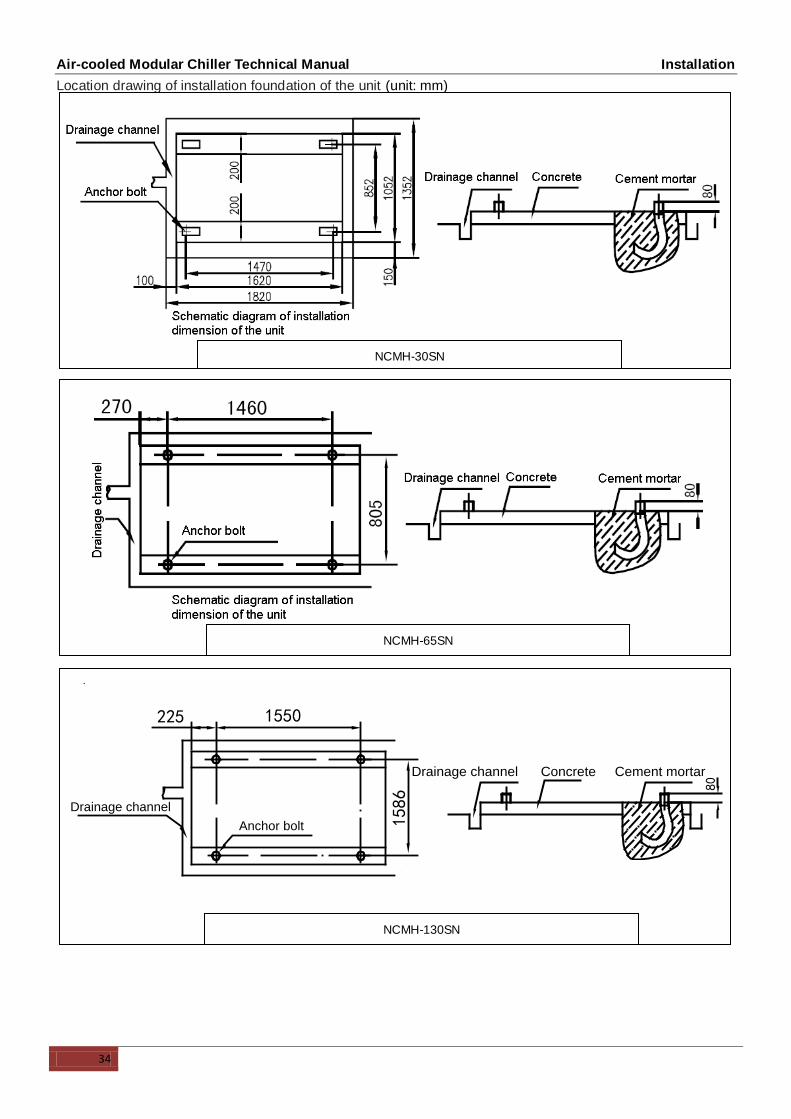
Location drawing of installation foundation of the unit (unit: mm)
3.5.1 Location drawing of installation foundation of the unit: (unit:
mm)
225
Drainage channel
Anchor bolt
1550
1586
80
Concrete Cement mortarDrainage channel
NCMH-30SN
NCMH-65SN
CLS-F130HU/S, CLS-F130HW/K, CLS-F130HU/SR1, CLS-1F30HU/KR1
NCMH-130SN

Air-cooled Modular Chiller Technical Manual Installation
35
1.4 Installation of damping devices
Damping devices must be provided between the unit and its foundation.
By means of the Φ15mm diameter installation holes on the steel frame of the unit base, the unit can be
fastened on the foundation through the spring damper. See upper pictures (Schematic diagram of installation
dimension of the unit) for details about center distance of the installation holes. The damper does not go with
the unit, and the user can select the damper according to the relevant requirements. When the unit is installed
on the high roof or the area sensitive to vibration, please consult the relevant persons before selecting the
damper
Installation steps of the damper
Step Content
1 Make sure that the flatness of the concrete foundation is within ±3mm, and then place the unit on the
cushion block.
2 Raise the unit to the height suitable for installation of the damping device. Remove the clamp nuts of the
damper.
3 Place the unit on the damper, and align the fixing bolt holes of the damper with the fixing holes on the unit
base.
4 Return the clamp nuts of the damper to the fixing holes on the unit base, and tighten them into the damper.
5 Adjust the operational height of the damper base, and screw down the leveling bolts. Tighten the bolts by
one circle to ensure equal height adjustment variance of the damper.
6 The lock bolts can be tightened after the correct operational height is reached.

Air-cooled Modular Chiller Technical Manual Installation
36
2. Water System Installation
Notice:
After the unit is in place, chilled water pipes can be laid.
The relevant installation regulations should be abided with when conducting connection of water pipes.
The pipelines should be free of any impurity, and all chilled water pipes must conform to local rules and
regulations of pipeline engineering.

Air-cooled Modular Chiller Technical Manual Installation
37
2.1 Basic requirements of connection of chilled water pipes
No. Content
1 All chilled water pipelines should be thoroughly flushed, to be free of any impurity, before the unit is operated. Any
impurity should not be flushed to or into the heat exchanger.
2 Water must enter the heat exchanger through the inlet; otherwise the performance of the unit will decline.
3
The inlet pipe of the evaporator must be provided with a target flow controller, to realize flow-break protection for the unit.
Both ends of the target flow controller must be supplied with horizontal straight pipe sections whose diameter is 5 times
that of the inlet pipe. The target flow controller must be installed in strict accordance with “Installation & Regulation Guide
for Target Flow Controller”. The wires of the target flow controller should be led to the electric cabinet through shielded
cable. The working pressure of the target flow controller is 1.0MPa, and its interface is 1 inch in diameter. After the
pipelines are installed, the target flow controller will be set properly according to the rated water flow of the unit.
4 The pump installed in the water pipeline system should be equipped with starter. The pump will directly press water into
the heat exchanger of the water system.
5 The pipes and their ports must be independently supported but should not be supported on the unit.
6 The pipes and their ports of the heat exchanger should be easy to disassemble for operation and cleaning, as well as
inspection of port pipes of the evaporator.
7 The evaporator should be provided with a filter with more than 40 meshes per inch at site. The filter should be installed
near to the inlet port as much as possible, and be under heat preservation.
8
The by-pass pipes and by-pass valves as shown in the figure of “Connection drawing of pipeline system” must be
mounted for the heat exchanger, to facilitate cleaning of the outside system of water passage before the unit is adjusted.
During maintenance, the water passage of the heat exchanger can be cut off without disturbing other heat exchangers.
9 The flexible ports should be adopted between the interface of the heat exchanger and on-site pipeline, to reduce transfer
of vibration to the building.
10 To facilitate maintenance, the inlet and outlet pipes should be provided with thermometer or manometer. The unit is not
equipped with pressure and temperature instruments, so they need to be purchased by the user.
11
All low positions of the water system should be provided with drainage ports, to drain water in the evaporator and the
system completely; and all high positions should be supplied with discharge valves, to facilitate expelling air from the
pipeline. The discharge valves and drainage ports should not be under heat preservation, to facilitate maintenance.
12 All possible water pipes in the system to be chilled should be under heat preservation, including inlet pipes and flanges of
the heat exchanger.
13
The outdoor chilled water pipelines should be wrapped with an auxiliary heating belt for heat preservation, and the
material of the auxiliary heat belt should be PE, EDPM, etc., with thickness of 20mm, to prevent the pipelines from
freezing and thus cracking under low temperature. The power supply of the heating belt should be equipped with an
independent fuse.
14
When the ambient temperature is lower than 2℃, and the unit will be not used for a long time, water inside the unit should
be drained. If the unit is not drained in winter, its power supply should not be cut off, and the fan coils in the water system
must be provided with three-way valves, to ensure smooth circulation of the water system when the anti-freezing pump is
started up in winter.
15 The common outlet pipelines of combined units should be provided with mixing water temperature sensor.
Warning:
For the water pipeline network including filters and heat exchangers, dreg or dirt may seriously damages the
heat exchangers and water pipes.
The installation persons or the users must ensure the quality of chilled water, and de-icing salt mixtures and air
should be excluded from the water system, since they may oxidize and corrode steel parts inside the heat
exchanger.

Air-cooled Modular Chiller Technical Manual Installation
38
2.2 Water Quality
Water quality control
When industrial water is used as chilled water, little furring may occur; however, well water or river water, used
as chilled water, may cause much sediment, such as furring, sand, and so on. Therefore, well water or river
water must be filtered and softened in softening water equipment before flowing into chilled water system. If
sand and clay settle in the evaporator, circulation of chilled water may be blocked, and thus leading to freezing
accidents; if hardness of chilled water is too high, furring may occur easily, and the devices may be corroded.
Therefore, the quality of chilled water should be analyzed before being used, such as PH value, conductivity,
concentration of chloride ion, concentration of sulfide ion, and so on.
Applicable standard of water quality for the unit
PH value Total
hardness Conductivity Sulfide ion Chloride ion
Ammonia
ion Sulfate ion Silicon Iron content Sodium ion
Calcium
ion
7~8.5 <50ppm <20μV/cm(25℃) No <50ppm No <50ppm <30ppm <0.3ppm No requirement <50ppm
2.3 Installation & regulation guide for target flow controller
Please carefully check flow switches before conducting installation of the target flow controller. Packing
should be in good condition, and the appearance should be free of damage and deformation. If any
problem, please contact the manufacturer.
Flow switches can be installed in the horizontal pipeline or the vertical pipeline with upward flowing
direction but cannot be mounted in the pipeline with downward flowing direction. The inlet water of gravity
should be taken into account when flow switches are installed in the pipeline with upward flowing direction.
Target flow controller must be installed on a section of straight-line pipeline, and it’s both ends must be
supplied with straight-line pipes whose length is at least 5 times diameter of the pipe. In the meanwhile,
the fluid flowing direction in the pipeline must be consistent with the direction of arrow on the controller.
The connection terminal should be located where wiring connection can be easily done.
Pay attention to the following items when conducting installation and wire connection:
Collision of the wrench with the soleplate of the flow switch is prohibited, since such collision may
cause deformation and failure of the flow switch.
To avoid electric shock and damages to the devices, the power supply should be cut off, when wires
are connected or adjustment is done.
When wiring connection is conducted, adjustment of other screws except connection terminals of
micro switches and ground screws is prohibited. In the meanwhile, over great force should not
applied when wires of micro switches are connected, otherwise micro switches may suffer
displacement, thus leading to failure of flow switches.
Special grounding screws should be used for earth connection. Bolts should not be installed or
removed at will; otherwise flow switches may suffer deformation and failure.
Flow switches have been set at minimal flow value before leaving the factory. They should not be
adjusted below the setting value at the factory, or they may suffer failure. After installing flow switches,
please press the flow switch lever several times to check them. When the lever is found not to
respond with “clatter”, rotate the screw in a clockwise direction, until “clatter” occurs.
Be sure to determine the model of target slice according to the rated flow of the unit, the diameter of
the outlet pipe and the adjustment range of the target slice of the flow switch. Besides, the target slice
should not contact with other restrictors in the pipeline or on the inner wall of the pipeline, or the flow
switch cannot be reset normally.
Determine whether the flow switch and the system connected with it are in good operation according to
the measured value by flow meter, namely, when the measured value on flow meter is less than 60% of
rated water flow of the unit, the target flow controller should be cut off and observed for 3 working periods,
and it should be covered with flow switch shell timely.

Air-cooled Modular Chiller Technical Manual Installation
39
Schematic diagram of target flow controller

Air-cooled Modular Chiller Technical Manual Installation
40
3. Installation of water system pipeline
The total outlet water pipe diameter after combined as below table:

Air-cooled Modular Chiller Technical Manual Installation
41
3.1 NCMH-30SN
Installation of single-module water system pipeline
Air-Cooled Modular Chiller Technical Manual Installation
42
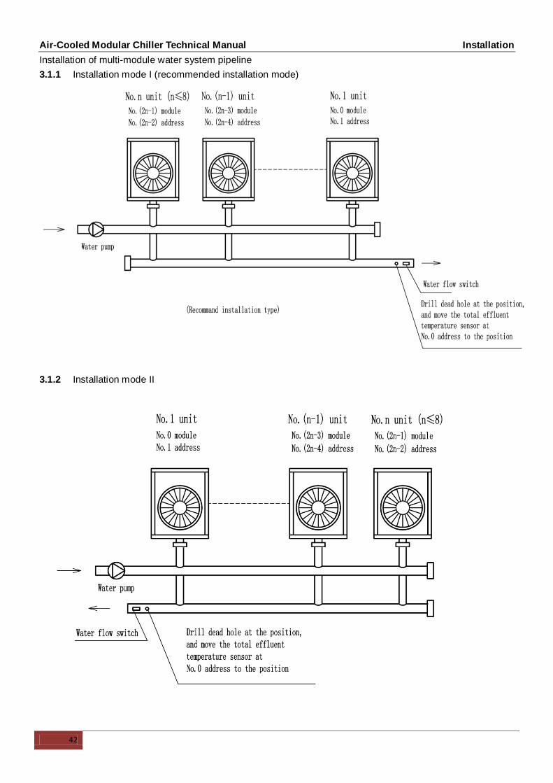
Installation of multi-module water system pipeline
3.1.1 Installation mode I (recommended installation mode)
3.1.2 Installation mode II

Air-Cooled Modular Chiller Technical Manual Installation
43
3.2 NCMH-65SN
Installation of single-module water system pipeline
Installation of multi-module water system pipeline
3.2.1 Installation mode I (recommended installation mode)
Less than 6 modes

Air-cooled Modular Chiller Technical Manual Installation
44
3.2.2 Installation mode II
3.2.3 Installation mode III (recommended installation mode)
Less than 6 modes
Installation mode A: less than 16 modules
Installation mode B: less than 16 modules

Air-cooled Modular Chiller Technical Manual Installation
45
3.2.4 Installation mode IV
Installation mode A: less than 16 modules
Installation mode B: less than 16 modules

Air-cooled Modular Chiller Technical Manual Installation
46
3.2.5 Installation mode V
Installation mode A: less than 16 modules
Installation mode B: less than 16 modules

Air-cooled Modular Chiller Technical Manual Installation
47
3.3 NCMH-130SN
Installation of single-module water system pipeline
Electric control box
Total water outlet
temp sensorWater intlet
Water outlet
Installation of multi-module water system pipeline
3.3.1 Installation mode I (recommended installation mode)

Air-cooled Modular Chiller Technical Manual Installation
48
3.3.2 Installation mode II
Notices :
For installation of multi-module, the most modules should be not more than 8 modular units.
For installation of multi-module, please drill a dead hole(Φ9mm) at the total water outlet pipeline, and
move the total water effluent temperature sensor at No.0 address to the hole.
Please pay attention to the following items when installing multiple modules:
Each module corresponds to an address code which cannot be repeated.
Main water outlet temperature sensing bulb, target flow controller and auxiliary electric heater are under
control of the main module.
One wired controller and one target flow controller are required and connected on the main module.
The unit can be started up through the wired controller only after all addresses are set and the
aforementioned items are determined. The wired controller is ≤50m away from the outdoor unit.

Air-cooled Modular Chiller Technical Manual Installation
49
4. Wiring Installation
All wiring installation should be done by qualified person.
4.1 Precautions:
The air-conditioner should apply special power supply, whose voltage should conform to rated voltage.
Wiring construction must be conducted by the professional technicians according to the labeling on the
circuit diagram.
Only use the electric components specified by our company, and require installation and technical
services from the manufacturer or authorized dealer. If wiring connection fails to conform to electric
installation norm, failure of the controller, electronic shock, and so on may be caused.
The connected fixed wires must be equipped with full switching-off devices with at least 3mm contact
separation.
Set leakage protective devices according to the requirements of national technical standard about electric
equipment.
After completing all wiring construction, conduct careful check before connecting the power supply.
Please carefully read the labels on the electric cabinet.
The user’s attempt to repair the controller is prohibited, since improper repair may cause electric shock,
damages to the controller, and so on. If the user has any requirement of repair, please contact the
maintenance center.
4.2 Requirements of Wiring Connection
No additional control components are required in the electric cabinet (such as relay, and so on), and the
power supply and control wires not connected with the electric cabinet are not allowed to go through the
electric box. Otherwise, electromagnetic interference may cause failure of the unit and control
components and even damages to them, which thus lead to protective failure.
All cables led to the electric box should be supported independently but by the electr ic box.
The strong current wires generally pass the electric box, and 220-240V alternating current may also pass
the control board, so wiring connection should conform to the principle of separation of strong current and
weak current, and the wires of power supply should be kept more than 100 mm away from the control
wires.
Only use rated power supply for the unit, and the maximum allowable range of voltage is 380V~415V.
All electric wires must conform to local wiring connection norm. The suitable cables should be connected
to power supply terminal through wiring connection holes at the bottom of the electric cabinet. According
to Chinese standard, the user is responsible for providing voltage and current protection for the input
power supply of the unit.
All power supplies connected to the unit must pass one manual switch, to ensure that the voltages on all
nodes of electric circuit of the unit are released when the switch is cut off.

Air-cooled Modular Chiller Technical Manual Installation
50
The cables of correct specification must be used to supply power for the unit. The unit should use
independent power supply, and the unit is not allowed to use the same power supply together with other
electric devices, to avoid over-load danger. The fuse or manual switch of the power supply should be
compatible with working voltage and current of the unit. In case of parallel connection of multiple modules,
the requirements of wiring connection mode and configuration parameters for the unit are shown in the
following figure.
Some connection ports in the electric box are switch signals, for which the user needs to provide power,
and the rated voltage of the power should be 380-415VAC. The user must be aware that all power
supplies they provided should be obtained through power circuit breakers (provided by the user), to
ensure that all voltages on the nodes of the provided power supply circuit are released when the circuit
breakers are cut off.
All inductive components provided by the user (such as coils of contactor, relay, and so on) must be
suppressed with standard resistance-capacitance suppressors, to avoid electromagnetic interference,
thus leading to failure of the unit and its controller and even damages to them.
All weak current wires led to the electric box must apply shielded wires, which must be provided with
grounding wires. The shield wires and power supply wires should be laid separately, to avoid
electromagnetic interference.
The unit must be provided with grounding wires, which are not allowed to be connected with the grounding
wires of gas fuel pipelines, water pipelines, lightning conductors or telephones. Improper earth connection
may cause electric shock, so please check whether earth connection of the unit is firm or not frequently.
Notes:
NCMH-30SN module only 16 modular units can be combined at most.
NCMH-65SN module only 16 modular units can be combined at most.
NCMH-130SN module only 16 modular units can be combined at most.
Ou
tdo
or
po
we
r su
pp
ly
Outdoor
unit 1
Outdoor
unit 2
Outdoor
unit 3
Outdoor
unit 4
Outdoor
unit N
Manual switch
Manual switch
Manual switch
Manual switch
Manual switch

Air-cooled Modular Chiller Technical Manual Installation
51
4.3 Wiring Steps
Step Content
1
Check the unit and ensure that it is connected with grounding wires correctly, to avoid leakage, and the
grounding devices should be mounted in strict accordance with the requirements of electrical engineering rules.
The grounding wires can prevent electric shock.
2 The control box of the main power switch must be mounted in a proper position.
3 Wiring connection holes of the main power should be provided with glue cushion.
4 The main power and neutral wires and grounding wires of power supply are led into the electric box of the unit.
5 The wires of the main power must pass the bonding clamp.
6 Wires should be connected firmly to the connection terminals L1, L2, L3 , N.
7 Phase sequences must be consistent when the wires of the main power.
8 The main power should be located out of easy reach of non-professional maintenance personnel, to avoid
mal-operation and improve safety.
4.4 Field wiring

Air-Cooled Modular Chiller Technical Manual Installation
52
5. Trial Operation
5.1 Points for Attention Prior to Trial Run
After the water system pipeline is flushed several times, please make sure that the purity of water meets the
requirements; the system is re-filled with water and drained, and the pump is started up, and then make sure
that water flow and the pressure at the outlet meet the requirements.
The unit is connected to the main power 12 hours before being started up, to supply power to the heating belt
and pre-heat the compressor. Inadequate pre-heating may cause damages to the compressor.
Set up the wired controller. See details of the manual concerning setting contents of the controller, including
such basic settings as refrigerating and heating mode, manual adjustment and automatic adjustment mode
and pump mode. Under normal circumstances, the parameters are set around standard operating conditions
for trial run, and extreme working conditions should be prevented as much as possible.
Carefully adjust the target flow controller on the water system or the inlet stop valve of the unit, to make the
water flow of the system be 90% of the water flow specified as below Table.

Air-Cooled Modular Chiller Technical Manual Installation
53
5.2 Check Items Table After Installation
Checking Items Description Yes No
Whether Installing Site Is
Meet for Requirement
Units are fixed mounting on level base.
Ventilating space for heat exchanger at the air side is
meeting for requirement.
Maintenance space is meeting for requirement.
Noise and vibration is meeting for requirement.
Sun radiation and rain for snow proof measures are
meeting for requirement.
External physical is meeting for requirement.
Whether Water System Is
Meeting for Requirements
Pipe diameter is meeting for requirement.
The length of system is meeting for requirement.
Water discharge is meeting for requirement.
Water quality control is meeting for requirement.
Flexible tube’s interface is meeting for requirement.
Pressure control is meeting for requirement.
Terminal insulation is meeting for requirement.
Wire capacity is meeting for requirement.
Switch capacity is meeting for requirement.
Fuse capacity is meeting for requirement.
Voltage and frequency are meeting for requirement.
Whether Electrical Wiring
System Is Meeting for
Requirement.
Connecting tightly between wires.
Operation control device is meeting for requirement.
Safety device is meeting for requirement.
Chained control is meeting for requirement.
Phase sequence of power supply is meeting for
requirement.

Air-Cooled Modular Chiller Technical Manual Installation
54
5.3 Trial Operation
Start up the controller and check whether the unit displays a fault code. If a fault occurs, remove the fault
first, and start the unit according to the operating method in the “unit control instruction”, after determining
that there is no fault existing in the unit.
Conduct trial run for 30 min. When the influent and effluent temperature becomes stabilized, adjust the
water flow to nominal value, to ensure normal operation of the unit.
After the unit is shut down, it should be put into operation 10 min later, to avoid frequent start-up of the unit.
In the end, check whether the unit meets the requirements according to the contents in upper table.
CAUTION
The unit can control start-up and shut-down of the unit, so when the water system is flushed, the operation
of the pump should not be controlled by the unit.
Do not start up the unit before draining the water system completely.
The target flow controller must be installed correctly. The wires of the target flow controller must be
connected according to electric control schematic diagram, or the faults caused by water breaking while
the unit is in operation should be the user’s responsibility.
Do not re-start the unit within 10 min after the unit is shut down during trial run.
When the unit is used frequently, do not cut off the power supply after the unit is shut down; otherwise the
compressor cannot be heated, thus leading to its damages.
If the unit is not in service for a long time, and the power supply needs to be cut off, the unit should be
connected to the power supply 12 hours prior to re-starting of the unit, to pre-heat the compressor.
Trail run and operation data
Temperature The table below contains the measurable temperatures.
Measurement Value
Inlet water temperature Standard cooling :7~25ºC
Standard heating:30~55 ºC
Outdoor temperature Standard cooling :10~48ºC
Standard heating:-10~24 ºC
Voltage Current The table below contains the measurable voltage.
Measurement Value
Power supply voltage Within ±10% of the rated voltage.
Phase imbalance Within ±2% of the rated voltage.
Control circuit voltage 380V AC for main electromagnetic switches,
Current The table below contains the currents and fuses.
Unit Maximum current(A) Fuse
30kW 25.5A 50
65kW 51A 100
130kW 102A 200

Air-cooled Modular Chiller Technical Manual Maintenance
55
Part 4. Maintenance
1. For Maintenance
1.1 Maintenance for main components:
Close attention should be paid to the discharge and suction pressure during the running process. Find out
reasons and eliminate the failure if abnormality is found.
Control and protect the equipment. See to it that no random adjustment be made on the set points on site.
Regularly check whether the electric connection is loose, and whether there is bad contact at the contact point
caused by oxidation and debris etc., and take timely measures if necessary. Frequently check the work voltage,
current and phase balance.
Check the reliability of the electric elements in time. Ineffective and unreliable elements should be replaced in
time.
1.2 Water quality inspection and dirt remove
According to the local water quality, please inspect the water regularly. We recommended you to respect it a
half year a time and change the circulate water two years a time.
After long-time operation, calcium oxide or other minerals will be settled in the heat transfer surface of the
water-side heat exchanger. These substances will affect the heat transfer performance when there is too much
scale in the heat transfer surface and sequentially cause that electricity consumption increases and the
discharge pressure is too high (or suction pressure too low). Organic acids such as formic acid, citric acid and
acetic acid may be used to clean the scale. But in no way should cleaning agent containing chlorine acid or
fluoride should be used as the water-side heat exchange is made from stainless steel and is easy to be eroded
to cause refrigerant leakage. Pay attention to the following aspects during the cleaning and scale-removing
process:
Water-side heat exchanger should be done be professionals.
Clean the pipe and heat exchanger with clean water after cleaning agent is used. Conduct water treatment
to prevent water system from being eroded or re-absorption of scale.
In case of using cleaning agent, adjust the density of the agent, cleaning time and temperature according
to the scale settlement condition.
After pickling is completed, neutralization treatment needs to be done on the waste liquid. Contact relevant
company for treating the treated waste liquid.
Protection equipments (such as goggles, gloves, mask and shoes) must be used during the cleaning
process to avoid breathing in or contacting the agent as the cleaning agent and neutralization agent is
corrosive to eyes, skins and nasal mucosa.
1.3 Winter shutdown
For shutdown in winter, the surface of the unit outside and inside should be cleaned and dried. Cover the unit
to prevent dust. Open discharge water valve to discharge the stored water in the clean water system to prevent
freezing accident (it is preferable to inject antifreeze in the pipe).

Air-cooled Modular Chiller Technical Manual Maintenance
56
1.4 Replacing parts
Parts to be replaced should be the ones provided by our company. Never replace any part with different part.
First startup after shutdown
The following preparations should be made for re-startup of unit after long-time shutdown:
Thoroughly check and clean the unit.
Clean water pipe system.
Check pump, control valve and other equipments of water pipe system.
Fix connections of all wires.
It is a must to electrify the machine before startup.
1.5 Refrigeration system
Determine whether refrigerant is needed by checking the value of suction and discharge pressure and check
whether there is a leakage. Air tight test must be made if there is a leakage, or part of refrigerating system is
replaced. Take different measures in the following two different conditions from refrigerant injection.
1.5.1 Total leakage of refrigerant. In case of such situation, leakage detection must be made on the
pressurized nitrogen used for the system. If repair welding is needed, welding cannot be made until all the gas
in the system is discharged. Before injecting refrigerant, the whole refrigeration system must be completely dry
and of vacuum pumping.
Total leakage of refrigerant. In case of such situation, leakage detection must be made on the pressurized
nitrogen used for the system. If repair welding is needed, welding cannot be made until all the gas in the
system is discharged. Before injecting refrigerant, the whole refrigeration system must be completely dry
and of vacuum pumping.
Remove air from the system pipe with vacuum pump. The vacuum pumping lasts for above 3 hours.
Confirm that the indication pressure in dial gauge is within the specified scope.
When the degree of vacuum is reached, inject refrigerant into the refrigeration system with refrigerant
bottle. Appropriate amount of refrigerant for injection has been indicated on the nameplate and the table of
main technical parameters. Refrigerant must be injected from the low pressure side of system.
The injection amount of refrigerant will be affected by the ambient temperature. If the required amount has
not been reached but no more injection can be done, make the chilled water circulate and start up the unit
for injection. Make the low pressure switch temporarily short circuit if necessary.
1.5.2 Refrigerant supplement. Connect refrigerant injection bottle on the fluoride nozzle at low-pressure side
and connect pressure gauge at low pressure side.
Make chilled water circulate and start up unit, and make the low pressure control switch short circuit if
necessary.
Inject refrigerant slowly into the system and check suction and discharge pressure.
CAUTION
Connection must be renewed after injection is completed.
Never inject oxygen, acetylene or other flammable or poisonous gas to the refrigeration system at leakag e
detection and air tight test. Only pressurized nitrogen or refrigerant can be used.
1.6 Disassembling compressor
Follow the following procedures if compressor needs to be disassembled:
Cut off the power supply of unit.
Remove power source connection wire of compressor.
Remove suction and discharge pipes of compressor.
Remove fastening screw of compressor.
Move the compressor.

Air-cooled Modular Chiller Technical Manual Maintenance
57
1.7 Auxiliary electric heater
When the ambient temperature is lower than 2℃, the heating efficiency decreases with the decline of the
outdoor temperature. In order to make the air-cooled heat pump stably run in a relatively cold region and
supplement some heat lost due to de-frosting. When the lowest ambient temperature in the user’s region in
winter is within 0 C~10 C, the user may consider using auxiliary electric heater. Please refer to relevant
professionals for the power of auxiliary electric heater.
1.8 System anti-freezing
In case of freezing at the water-side heat exchanger interval channel, severe damage may be caused, i.e. heat
exchange may be broken and appears leakage. This damage of frost crack is not within the warranty scope, so
attention must be paid to anti-freezing.
1.8.1 If the unit that is shut down for standby is placed in an environment where the outdoor temperature is
lower than 0oC, the water in the water system should be drained.
1.8.2 Water pipe may be frozen when the chilled water target flow controller and anti-freezing temperature
senor become ineffective at running, therefore, the target flow controller must be connected in accordance with
the connection diagram.
1.8.3 Frost crack may happen to water-side heat exchanger at maintenance when refrigerant is injected to the
unit or is discharged for repair. Pipe freezing is likely to happen any time when the pressure of refrigerant is
below 0.4Mpa. Therefore, the water in the heat exchanger must be kept flowing or be thoghly discharged.
Air-cooled Modular Chiller Technical Manual Maintenance
58
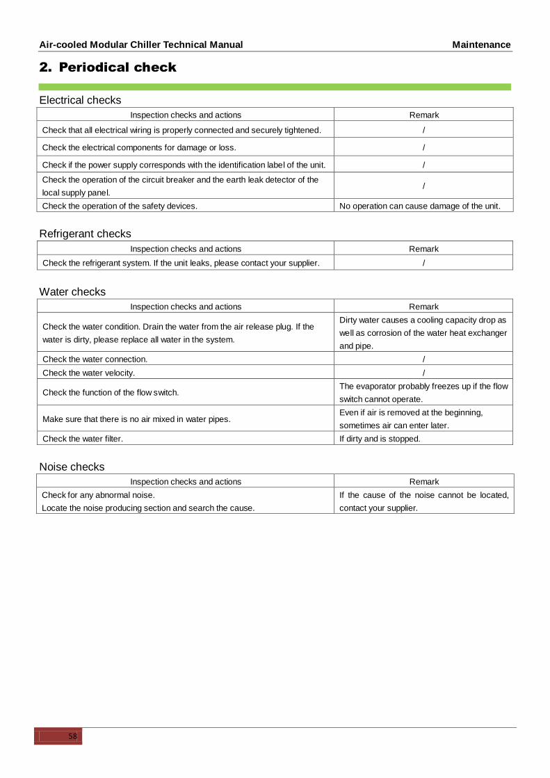
2. Periodical check
Electrical checks
Inspection checks and actions Remark
Check that all electrical wiring is properly connected and securely tightened. /
Check the electrical components for damage or loss. /
Check if the power supply corresponds with the identification label of the unit. /
Check the operation of the circuit breaker and the earth leak detector of the
local supply panel. /
Check the operation of the safety devices. No operation can cause damage of the unit.
Refrigerant checks
Inspection checks and actions Remark
Check the refrigerant system. If the unit leaks, please contact your supplier. /
Water checks
Inspection checks and actions Remark
Check the water condition. Drain the water from the air release plug. If the
water is dirty, please replace all water in the system.
Dirty water causes a cooling capacity drop as
well as corrosion of the water heat exchanger
and pipe.
Check the water connection. /
Check the water velocity. /
Check the function of the flow switch. The evaporator probably freezes up if the flow
switch cannot operate.
Make sure that there is no air mixed in water pipes. Even if air is removed at the beginning,
sometimes air can enter later.
Check the water filter. If dirty and is stopped.
Noise checks
Inspection checks and actions Remark
Check for any abnormal noise.
Locate the noise producing section and search the cause.
If the cause of the noise cannot be located,
contact your supplier.

Air-cooled Modular Chiller Technical Manual Wired Controller
59
Part 5. Wired Controller

Air-Cooled Modular Chiller Technical Manual Wired Controller
60

Air-cooled Modular Chiller Technical Manual Appendix
61
Appendix
1. Accessories
Item Name of accessory Type Qty Shape Usage
1 Installation and owner's
manual --- 1
Installation and using
instruction.
3 Wired controller 1
Control the system.

Air-cooled Modular Chiller Technical Manual Appendix
62
2. Temperature-Resistance Characteristic Sheet
Suiting for pipe temperature sensor,ambient temperature sensor,inlet water temperature sensor and outlet
water temperature sensor.
Sensor characteristic sheet Unit:Temp:℃, Resistance :KΩ
Temp. Resistance Temp. Resistance Temp. Resistance Temp. Resistance
-20 106.732 12 18.646 44 4.387 76 1.321
-19 100.552 13 17.743 45 4.213 77 1.276
-18 94.769 14 16.888 46 4.046 78 1.233
-17 89.353 15 16.079 47 3.887 79 1.191
-16 84.278 16 15.313 48 3.735 80 1.151
-15 79.521 17 14.588 49 3.59 81 1.113
-14 75.059 18 13.902 50 3.451 82 1.076
-13 70.873 19 13.251 51 3.318 83 1.041
-12 66.943 20 12.635 52 3.191 84 1.007
-11 63.252 21 12.05 53 3.069 85 0.974
-10 59.784 22 11.496 54 2.952 86 0.942
-9 56.524 23 10.971 55 2.841 87 0.912
-8 53.458 24 10.473 56 2.734 88 0.883
-7 50.575 25 10 57 2.632 89 0.855
-6 47.862 26 9.551 58 2.534 90 0.828
-5 45.308 27 9.125 59 2.44 91 0.802
-4 42.903 28 8.721 60 2.35 92 0.777
-3 40.638 29 8.337 61 2.264 93 0.753
-2 38.504 30 7.972 62 2.181 94 0.73
-1 36.492 31 7.625 63 2.102 95 0.708
0 34.596 32 7.296 64 2.026 96 0.686
1 32.807 33 6.982 65 1.953 97 0.666
2 31.12 34 6.684 66 1.883 98 0.646
3 29.528 35 6.401 67 1.816 99 0.627
4 28.026 36 6.131 68 1.752 100 0.609
5 26.608 37 5.874 69 1.69 101 0.591
6 25.268 38 5.63 70 1.631 102 0.574
7 24.003 39 5.397 71 1.574 103 0.558
8 22.808 40 5.175 72 1.519 104 0.542
9 21.678 41 4.964 73 1.466 105 0.527
10 20.61 42 4.763 74 1.416
11 19.601 43 4.571 75 1.367