air control units - taiyo-ltd.co.jp control units handling instructions frl 6 vj handling...
TRANSCRIPT

FRL
Air Control Units
Product Configuration/Handling Instructions …… VJ2
Air Control Units 2-piece Set………………… VJ8
Air Control Units 3-piece Set…………………VJ14
Filter Regulators……………………………………VJ22
Air Filters……………………………………………
Air Regulators………………………………………VJ36
Air Lubricators………………………………………VJ50
Auto Drain Traps…………………………………VJ58
Micro-filters …………………………………………VJ62
Mist Separators……………………………………VJ70
Residual Pressure Discharge Valves ………VJ78
Option Sets …………………………………………VJ82
Pressure Gauges with Pointers………………VJ98
Pressure Sensors with Analog Display ……
VJ28
VJ99

Product Confi gurationAir Control UnitsFRL
2VJ
Product Confi guration Air Control UnitsFRL
3VJ
Model numberPort size(Rc)
PageModel
Air Control Units2-piece Set
Air Control Units3-piece Set
Filter Regulators
Air Regulators
Air Regulatorswith Check Valve
Air Lubricators
Air Filters
SKL
EKL
MKL
SFRL
EFRL
MFRL
HFRL
SFR
EFR
MFR
SAF
EAF
MAF
HAF
SRV
ERV
MRV
HRV
SRC
ERC
MRC
HRC
SAL
EAL
MAL
HAL
1/8 1/4 3/8 1/2 3/4 1
VJ8
VJ10
VJ12
VJ14
VJ16
VJ18
VJ20
VJ22
VJ24
VJ26
VJ28
VJ30
VJ32
VJ34
VJ36
VJ40
VJ44
VJ48
VJ36
VJ40
VJ44
VJ48
VJ50
VJ52
VJ54
VJ56
EDS
MDS
SFF
EFF
MFF
HFF
SMF
EMF
MMF
HMF
SSV
ESV
SKL
SFRL
EKL
EFRL
MKL
MFRL
PG301DH
PG202DH
DAS
Auto Drain Traps
Micro-filters
Mist Separators
Residual PressureDischarge Valves
Option SetsWith Branch BlockWith Pressure SensorWith Residual PressureDischarge Valve
Pressure Gaugeswith Pointers
Pressure Sensors withAnalog Display
1/8 1/4 3/8 1/2 3/4 1
VJ98
VJ98
VJ99
VJ84
VJ84
VJ85
VJ85
VJ90
VJ90
VJ58
VJ60
VJ62
VJ64
VJ66
VJ68
VJ70
VJ72
VJ74
VJ76
VJ78
VJ80
Model numberPort size(Rc)
PageModel

Handling InstructionsAir Control UnitsFRL
4VJ
Handling Instructions Air Control UnitsFRL
5VJ
Air Filters
Drain
Drainupper limit
Lightly press.
45°
Concavityin stopper Convexity
on stopper
P1
Primaryside
P2
Secondaryside
P1ーP2 0.07MPa
Rising pipe ×
5 m or more ×
Maintenance
Discharge of drain
CAUTION
●Discharge drain before the drain level exceeds the indicated upper limit. If the level exceeds the upper limit, drain will flow into the piping. When the amount of drain is large, use an automatic drain valve.●Manual draining ○Lightly press the drain tube from a side to tilt the drain lever, and drain will be discharged.
●Notes on use of automatic drain valve ○Do not use an automatic drain valve in a place subject to vibration. Doing so can cause operation failure.
○When piping the drain outlet of the automatic drain valve, use a pipe less than 5 m long, and avoid raising the pipe. Otherwise, drain may not be discharged.
○The working pressure of a differential pressure type automatic drain valve must be 0.1 MPa or more. The pressure difference between the IN and OUT sides of the piping at the start of air flowing must be 0.05 MPa or more. If the pressure or pressure difference is low, the valve may not operate. (SAF Series)
○The working pressure of a float type automatic drain valve must be 0.15 MPa or more. Ensure an air flow rate of 150 ℓ/min or more through the piping. Otherwise, leak from the drain outlet may not stop. (EAF, MAF, and HAF Series) The auto drain may not operate correctly due to dirt and contaminants. Periodically check the valve.
●To remove the case, hold down the stopper and turn the case 45゚. Before removing the case, make sure that the pressure in the case has been reduced to 0.
●Use a micro-filter or a mist separator at a recommended max. flow rate or less.
If the flow rate is higher, oil mist cannot be trapped.
●To clean the case, use a neutral dish detergent.●Before attaching the case, make sure that the O-ring has been correctly fitted. Then, attach the case in the reverse order to removal. If the O-ring has not been fitted correctly, air may leak.●Replace the filter element with a new one when the pressure difference between the primary and secondary sides in use exceeds 0.07 MPa.
●Do not use the device in a place where there is a possibility of adhesion of organic solvents (thinner, trichlene, etc.), alkaline solutions or acid solutions. The case is made of polycarbonate. Adhesion of any organic solvent, alkaline solution or acid solution to the case may rupture the case, thereby causing a seriously hazardous situation.
●If the device has been dropped or subjected to a strong impact, do not use it. If any part has been damaged, air may leak, or the case may be ruptured, thereby causing a hazardous situation.
●Before removing the case, reduce the pressure in the case to 0. If the case with residual pressure is removed, it may be blown out, thereby causing a hazardous situation.
Air Regulators
Pressureadjustingknob
Pressureincreases.
Pressuredecreases.
Pressure adjusting procedure
Notes on use of pressure gauge
Maintenance
○Do not use the pressure gauge in a place subject to vibration.○Do not use the pressure gauge in a place subject to severe pressure fluctuation (pulsation) (just before or after a valve or near a compressor). If it must be used in such a place, fit a throttle, etc. to avoid direct transmission of pressure fluctuation to the pressure gauge.○When installing the pressure gauge, fit a spanner to the square part of the mounting port. If force is applied to any other part, the part may be damaged.
●Periodically check the set pressure.
●The air regulator can be installed downward as shown below. Relocate the pressure gauge.
○The air regulator pressure can be increased by pulling up the adjusting knob and turning it clockwise and can be reduced by turning it counterclockwise. After adjusting the pressure, lightly press it to lock.
●Before adjusting the pressure, check the specifications (max. working pressure) of the secondary equipment and the safety (cylinder operation). Failure to do so may damage the secondary equipment or cause an unexpected motion of the equipment, resulting in an accident.●If the device has been dropped or subjected to a strong impact, do not use it. If any part has been damaged, air may leak, or the device may malfunction.●Feed air which has passed an air filter (pore size of 40 μm or less).
CAUTION

Handling InstructionsAir Control UnitsFRL
6VJ
Handling Instructions Air Control UnitsFRL
7VJ
Air Lubricators
Turbine oil
Turbine oilSupplyplug
Recommended Turbine OilsNameManufacturer
Diana Freccia S-32Turbine oil 32COSMO Turbine 32Turbine 32Shell Vitrea 32Turbine oil 32Mitsui Turbine Oil 32
IdemitsuKYGNUSCosmo Oil LubricantsJapan Energy (JOMO)Showa Shell SekiyuNippon OilMitsui Oil
Adjustment of lubricant drip rate
Supply of lubricant
Installation of air lubricator
●Do not use machine oil or spindle oil. Doing so can cause operation failure or trouble.
●For the air lubricator, use a lubricant equivalent to non-additive turbine oil Class 1 (ISO VG32).
●Adjust the lubricant drip rate using the drip rate adjusting knob. Turn the knob clockwise, and the rate will be decreased. Turn it counterclockwise, and the rate will be increased.
●The standard amount of lubricant is 3 to 6 drops for an air flow rate of 1000 ℓ/min (ANR).
●The distance from the air lubricator to the device to be lubricated (cylinder, etc.) shall be less than 5 m. Otherwise, the lubricant may not reach the device.●Install the air lubricator higher than the device to be lubricated (cylinder, etc.). Otherwise, the lubricant may not reach the device. If the pipe is raised, the height of the rising zone shall be less than 0.5 m.●The air flow rate of the air lubricator shall be higher than the minimum drip rate.
●The air lubricator can be filled with a lubricant by removing the supply plug without stopping the main pressure. When the supply plug is removed, air may be suddenly spouted. Remove it carefully.●If lubricant cannot be fed through the supply plug, remove the case, and feed the lubricant. Before removing the case, remove the supply plug, and wait until the residual pressure reduces to 0. For the procedures for removing and attaching the case, refer to Air Filters.●Do not pour the lubricant over the upper limit. Replenish the lubricator before the lubricant level drops below the lower limit.
CAUTION
Decrease Increase
●Do not use the device in a place where there is a possibility of adhesion of organic solvents (thinner, trichlene, etc.), alkaline solutions or acid solutions. The case is made of polycarbonate. Adhesion of any organic solvent, alkaline solution or acid solution to the case may rupture the case, thereby causing a seriously hazardous situation.●If the device has been dropped or subjected to a strong impact, do not use it. If any part has been damaged, air may leak, or the case may be ruptured, thereby causing a hazardous situation.●Before removing the case, reduce the pressure in the case to 0. If the case with residual pressure is removed, it may be blown out, thereby causing a hazardous situation.●Do not fill the air lubricator with machine oil or spindle oil. Doing so can cause operation failure or trouble.●Do not turn the drip adjusting needle of SAL or HAL 4 turns or more from the fully closed state. If the needle is turned excessively, it will jump out, thereby causing a hazardous situation.●Feed air which has passed an air filter (pore size of 40 μm or less).
Primary side
Secondary side
60 mm or more
60 mm or more
General precautions
●Install it vertically supporting with the bracket or steel pipe.●Use it within the specified range.●Keep a space of 60 mm or more above and below it. This facilitates maintenance.
●Avoid direct sunlight.●Before piping the lubricator, be sure to flush the inside to remove foreign matter (sealing tape, cuttings, rust, etc.).●Install the lubricator aligning the air flow direction and the arrow direction.

8VJ
9VJ
SKL
FRL
Air Control Unit/2-piece SetPort Size:Rc1/8・Rc1/4SKL Air Control Unit/2-piece Set
Port Size:Rc1/8・Rc1/4 SKLFRL SKL
Unit: mm
CAD/DATAis available.FRL/TSFRL
How to Order
Explanation of Symbols
When placing an order, specify the model number shown below.
SKL-08 - * Series
Port sizeAccessories (in alphabetic order)
Example: Port size Rc1/4, with type D pressuregauge, with bracket SKL-08-BD
Port size
AccessoriesWith manual drain valveWith type D pressure gaugeWith type Q pressure gaugeWith bracket
With case guardWith nylon caseDifferential pressure type auto drainWith metallic case (without gauge)
06
D Q B
G N A M
Rc1/8
SKL-06 SKL-08
SFR-06 SFR-08
SAL-06 SAL-08
Models to be Combined Sectional DrawingModel number
Models to be CombinedFilter regulators Air lubricators
SKL-06
1/8 1/4
0.480.50
0.470.49
SKL-08
Note) The differential pressure type auto drain cannot beattached to any unit with a metallic or nylon case.
151 MPa
0.05 to 0.9 MPa1.6 MPa
0 to +60℃(No freezing)516
Quick manual drainingTurbine oil Class 1 (additive-free) ISO VG32 or its equivalent
25
Model numberItem
Port sizeMin. lubricant drip rateMax. working pressureSet pressure rangeProof test pressureWorking temperature rangeFilter elementDrain accumulationDraining methodRecommended lubricantOil tank capacity
Rc ℓ/min(ANR)
μm cm3
cm3
*
Specifications
* Rate when about 5 drops of turbine oil are given for 1 min at a set pressure (primary pressure) of 0.5 MPa.Note) The minimum working pressure of the differential pressure type auto drain is 0.1 MPa, and its min.
operating differential pressure is 0.05 MPa.
Weight kg
Accessories
Manual draining
Automatic draining
08 Rc1/4
None
JIS symbol
❶
❶
❷
❷
B.L. Combination TD08 is recommended.F.R.L.
●Standardized smart square forms, and light and compact bodies.●Devices can be easily combined with connecting screws.●Quick and easy drain.●Pressure can be adjusted smoothly with the round knob.The knob can be locked easily with a single touch of the mechanism.
A compact unit consisting of air filter, air regulator and air lubricator indispensable for pneumatic equipment. This unit is designed to clean compressed air, adjust the pressure and supply a lubricant to pneumatic equipment.
D:Type D pressure gauge Q:Type Q pressure gauge B:Bracket G:Case guardN:Nylon case A:Differential pressure type auto drain M:Metallic case (without gauge)
Lubricant
Flow sensor
IN OUT
Drain
SKL
Flow Characteristic Curves
SKL-06・08
SKL-06・08
SKL-06・08
Pressure Characteristic Curve
Min. Dripping Air Flow Rate Curve
PG301D
PG301Q
D:Type D pressure gauge
Q:Type Q pressure gauge
B:Bracket
SS-B
Port size:R1/8For 1 MPa
Port size:R1/8For 1 MPa
0.1
0 200 400 600 800 1000
0.2
0.3
0.4
0.5
0.6
0.7
0.8
Flow rate ℓ/min(ANR)
Flow rate ℓ/min(ANR)
Primary pressure : 0.8 MPa
Primary pressure : MPa
0.18
0 0.2 0.4 0.6 0.8 1
0.19
0.20
0.21
0.22
0.23
First set pointPrimary pressure : 0.7 MPaSecondary pressure : 0.2 MPa
0.1
0 10 20 30 40 50
0.2
0.3
0.4
0.5
0.6
0.7
0.8
SAF-M(with manual drain valve)
M:Metallic case (without gauge)
For filter regulator,without gauge
For air lubricatorSAL-M(without gauge)
85.540
83
83.5
31
71
185.5
71
82
30
183
27
38
5719
76
IN OUT
Vinyl hose for drain
2ーRc1/8(Pressure gauge mounting ports)
4.51.5
R2.25
●With metallic case(without gauge)
Enlarged view of mounting hole
20
2
6
38
25(48)
(73)
M30×2
2ーRc1/8Rc1/4
With automaticdrain valve
Mounting hole(See the figure below.)
Accessories SZZ
Secondary pressure MPa
Secondary pressure MPa
Primary pressure MPa

10VJ
11VJAir Control Unit/2-piece Set
Port Size:Rc1/4・Rc3/8・Rc1/2EKL Air Control Unit/2-piece SetPort Size:Rc1/4・Rc3/8・Rc1/2 EKL
EKL
FRL FR
L EKL
Unit: mm
CAD/DATAis available.FRL/TEFRL
1.05 1.07
1.03 1.05
1.01 1.03
30 30
Model numberItem
EKL-08 EKL-10 EKL-15
Specifications
EKL-10 - * Series
Port sizeAccessories
(in alphabetic order)Example: Port size Rc3/8, with automatic drain valve, with type
Q pressure gauge, with bracket EKL-10-ABQ
* Rate when about 5 drops of turbine oil are given for 1 min at a set pressure (primary pressure) of 0.5 MPa.Note) The min. working pressure of the unit with an automatic drain valve is 0.15 MPa.
Port size
Accessories
0810
A B D
Q N S
15 Rc1/2Rc1/4 Rc3/8
With manual drain valveWith automatic drain valveWith bracketWith type D pressure gauge
With type Q pressure gaugeWith nylon caseWith metallic case (with gauge)
EKL-08 EKL-10 EKL-15
EFR-08 EFR-10 EFR-15
EAL-08 EAL-10 EAL-15
A:Automatic drain valveD:Type D pressure gaugeQ:Type Q pressure gauge
B:BracketN:Nylon caseS:Metallic case (with gauge)
Models to be Combined Sectional DrawingModels to be Combined
1/4 1/2 3/8 25
1 MPa 0.05 to 1 MPa
1.6 MPa 0 to +60℃(No freezing)
5 60
Standard:Quick manual draining Semi-standard:Float type automatic drain
Turbine oil Class 1 (additive-free) ISO VG32 or its equivalent100
Explanation of Symbols
JIS symbol
❶
❶
❷
❷
B.L. Combination TD18 is recommended.F.R.L.
●Standardized smart square forms, and light and compact bodies.●Devices can be easily combined with connecting bolts.●The use of the quick clamp facilitates removal of the case and maintenance.
●Pressure can be adjusted smoothly with the round knob. The knob can be locked easily with a single touch of the mechanism.
●Lubrication can be performed by removing the supply plug without stopping the main pressure.
●The case guard is supplied as a standard device.
A compact unit consisting of air filter, air regulator and air lubricator indispensable for pneumatic equipment. This unit is designed to clean compressed air, adjust the pressure and supply a lubricant to pneumatic equipment.
Port sizeMin. lubricant drip rateMax. working pressureSet pressure rangeProof test pressureWorking temperature rangeFilter elementDrain accumulationDraining methodRecommended lubricantOil tank capacity
Rc ℓ/min(ANR)
μm cm3
cm3
*
Weight kg
Accessories
Manual draining
Automatic draining
Model numberFilter regulators Air lubricators
None
How to Order When placing an order, specify the model number shown below.
IN OUT
Drain
Lubricant
Gauge
Vinyl hosefor drain Gauge
EKL
Flow Characteristic CurvesEKL-08 EKL-10・15
Pressure Characteristic CurveEKL-08・10・15
Min. Dripping Air Flow Rate Curve
Accessories SZZA:Automatic drain valve
EAF-A
PG202D
EAF-S(manual drain valve)EAF-AS(automatic drain valve)
PG202Q
S:Metallic case (with gauge)
For filter regulator,with gauge
For air lubricatorEAL-S(with gauge)
D:Type D pressure gauge Q:Type Q pressure gauge
B:Bracket Bracket
EE-B ES-B
Port size:R1/4For 1 MPa
Port size:R1/4For 1 MPa
Primary pressure : 0.8MPa Primary pressure : 0.8MPa0.8
0.7
0.6
0.5
0.4
0.3
0.2
0.1
0 400 800 1200 1600 2000Flow rate ℓ/min(ANR)
0.8
0.7
0.6
0.5
0.4
0.3
0.2
0.1
0 400 800 1200 1600 2000Flow rate ℓ/min(ANR)
Primary pressure : MPa
0.22
0.21
0.20
0.19
0.18
0 0.2 0.4 0.6 0.8 1
First set pointPrimary pressure :0.7 MPaSecondary pressure :0.2 MPa
10.90.80.70.60.50.40.30.20.1
0 10 20 30 40 50 60 70 80Flow rate ℓ/min(ANR)
EKL-08EKL-10・15
●With metallic case(with gauge)
Secondary pressure MPa
Secondary pressure MPa
Secondary pressure MPa
Primary pressure MPa
12694.531.5
78□6356
256(247.5)
100
129.5
26.5(18)
Vinyl hose for drain
With automatic drain valve34
129.5
OUTIN
55
Mounting hole(See the figure below.)
2ーRc1/4(Pressure gauge mounting ports)
(121.5)(65.5) 56
M42×2 2.6
25
Rc1/4Rc3/8Rc1/2
2-
259.5(248.5)
100
126.5 126.5
Fit a tube with an innerdiameter of 8 mm to this part.( (
33(22)
Enlarged view of mounting hole
R3.256.5
10
The parenthesized values are the dimensionsof the unit with an automatic drain valve.

12VJ
13VJAir Control Unit/2-piece Set
Port Size:Rc1/2・Rc3/4MKL Air Control Unit/2-piece SetPort Size:Rc1/2・Rc3/4 MKL
MKL
FRL FR
L MKL
Unit: mm
CAD/DATAis available.FRL/TMFRL
MKL-15 - *
Example: Port size Rc1/2, with automatic drain valve, with typeQ pressure gauge, with bracket MKL-15-ABQ
Port size
Accessories
15
NoneA 5 D Q
B M S N
20 Rc3/4Rc1/2
With manual drain valveWith automatic drain valveWith 5-μm filter elementWith type D pressure gaugeWith type Q pressure gauge
With bracketWith metallic case (without gauge)With metallic case (with gauge)With nylon case
MKL-15 MKL-20
MFR-15 MFR-20
MAL-15 MAL-20
Models to be Combined Sectional DrawingModels to be Combined
1/2 3/425 30
Model numberItem
Specifications
* Rate when about 5 drops of turbine oil are given for 1 min at a set pressure (primary pressure) of 0.5 MPa.Note) The min. working pressure of the unit with an automatic drain valve is 0.15 MPa.
MKL-15
1.781.83
1.731.78
MKL-20
1 MPa0.05 to 1 MPa
1.6 MPa0 to +60℃(No freezing)
Standard : 40 Semi-standard : 560
Standard: Quick manual draining Semi-standard: Float type automatic drain
130
S : Metallic case (with gauge)N : Nylon case
A : Automatic drain valve 5 : 5-µm filter element D : Type D pressure gauge
Q : Type Q pressure gauge B : Bracket M : Metallic case (without gauge)
Explanation of Symbols
JIS symbol
❶
❶
❷
❷
B.L. Combination TD28 is recommended.F.R.L.
●Standardized smart square forms, and light and compact bodies.●Devices can be easily combined with connecting bolts.●The use of the quick clamp facilitates removal of the case and maintenance.
●The pressure can be adjusted smoothly with a large round knob.The knob can be locked easily with a single touch of the mechanism.
●Lubrication can be performed by removing the supply plug without stopping the main pressure.
●The case guard is supplied as a standard device.
A compact unit consisting of air filter, air regulator and air lubricator indispensable for pneumatic equipment. This unit is designed to clean compressed air, adjust the pressure and supply a lubricant to pneumatic equipment.
Port sizeMin. lubricant drip rateMax. working pressureSet pressure rangeProof test pressureWorking temperature rangeFilter elementDrain accumulationDraining methodRecommended lubricantOil tank capacity
Rc ℓ/min(ANR)
μm cm3
cm3
*
Weight kg
Accessories
Manual draining
Automatic draining
Turbine oil Class 1 (additive-free) ISO VG32 or its equivalent
Model numberFilter regulators Air lubricators
Series
Port sizeAccessories (in alphabetic order)
How to Order When placing an order, specify the model number shown below.
IN
Drain
OUT
Lubricant
MKL
Flow Characteristic CurvesMKL-15 MKL-20
Pressure Characteristic CurveMKL-15・20
Min. Dripping Air Flow Rate Curve
Accessories SZZA:Automatic drain valve
MAF-A
PG102D PG102Q
5:5-μm filter element
5μm:MAF-540μm:MAF-40
D:Type D pressure gauge Q:Type Q pressure gaugePort size:R1/4For 1 MPa
Port size:R1/4For 1 MPa
0.1
0 1000 2000 3000 4000 5000
0.2
0.3
0.4
0.5
0.6
0.7
0.8
Flow rate ℓ/min(ANR)
Primary pressure : 0.8 MPa
0
0.18
0.19
0.20
0.21
0.22
0.2 0.4 0.6 0.8 1
First set pointPrimary pressure : 0.7 MPaSecondary pressure : 0.2 MPa
Primary pressure : MPa
0.1
0 1000 2000 3000 4000 5000
0.2
0.3
0.4
0.5
0.6
0.7
0.8Primary pressure : 0.8 MPa
0.2
0 10 20 30 40 50
0.4
0.6
0.8
1.0
MKL-15
MKL-20
M:Metallic caseS:Metallic case (with gauge)
B:Bracket (with 4 hex. socket headcap screws)
MM-B
For filter regulator,・without gauge MAF-M(with manual drain valve) MAF-AM(with automatic drain valve)・with gauge MAF-S(with manual drain valve) MAF-AS(with automatic drain valve)
For air lubricatorMAL-M(without gauge)MAL-S(with gauge)
Flow rate ℓ/min(ANR)
Flow rate ℓ/min(ANR)
58.5
134
113.5
38.5(20)
286(267.5)
138
OUTIN
55
72
36 108
144
30
(74)
72
59.5
2.6
(133.5)
74
R3.5
Vinyl hose for drain With automaticdrain valve
2ーRc1/2Rc3/4141.9
182.5(163.8)
113.5
296(277.3)
Gauge GaugeVinyl hose for drain
2ーRc1/4(Pressure gauge mounting ports)
IN OUT
●With metallic case(without gauge/with gauge)
Enlarged view of mounting hole
The parenthesized values are the dimensionsof the unit with an automatic drain valve.
Mounting hole(See the figure below.)
Fit a tube with an innerdiameter of 8 mm to this part.( (
Secondary pressure MPa
Secondary pressure MPa
Secondary pressure MPa
Primary pressure MPa

14VJ
15VJAir Control Unit/3-piece Set
Port Size:Rc1/8・Rc1/4SFRL Air Control Unit/3-piece SetPort Size:Rc1/8・Rc1/4 SFRL
SFRL
FRL FR
L SFRL
Unit: mm
CAD/DATAis available.FRL/TSFRL
JIS symbol
SFRL 08 -*
Example: Port size Rc1/4, with type D pressuregauge, with bracket SFRL08-BD
Port size
06
D Q B
G N A M
08 Rc1/4Rc1/8
SFRL06 SFRL08
SAF-06 SAF-08
SRV-06 SRV-08
Models to be Combined Sectional DrawingModel number
Models to be CombinedAir filters Air regulators
SAL-06 SAL-08
Air lubricators
1/8 1/4
Note) The differential pressure type auto drain cannot beattached to any unit with a metallic or nylon case.
SpecificationsSFRL06
0.650.67
0.640.66
SFRL08
151 MPa
0.05 to 0.9 MPa 1.6 MPa
0 to +60℃(No freezing)5
16Quick manual draining
Turbine oil Class 1 (additive-free) ISO VG32 or its equivalent25
D:Type D pressure gauge Q:Type Q pressure gauge B:Bracket G:Case guard N:Nylon case A:Differential pressure type auto drain M:Metallic case (without gauge) * Rate when about 5 drops of turbine oil are given for 1 min at a set pressure (primary pressure) of 0.5 MPa.
Note) The min. working pressure of the differential pressure type auto drain is 0.1 MPa, and its min. operatingdifferential pressure is 0.05 MPa.
Explanation of Symbols
With manual drain valveWith type D pressure gaugeWith type Q pressure gaugeWith bracket
With case guardWith nylon caseDifferential pressure type auto drainWith metallic case (without gauge)
❶
❶
❷
❷
F.R.L. Combination TC08 is recommended.F.R.L.
●Standardized smart square forms, and light and compact bodies.●Devices can be easily combined with connecting screws.●Quick and easy drain.●Pressure can be adjusted smoothly with the round knob.The knob can be locked easily with a single touch of the mechanism.
Unit consisting of air filter, air regulator and air lubricator indispensable for pneumatic equipment. This unit is designed to clean compressed air, adjust the pressure and supply a lubricant to pneumatic equipment.
Port sizeMin. lubricant drip rateMax. working pressureSet pressure rangeProof test pressureWorking temperature rangeFilter elementDrain accumulationDraining methodRecommended lubricantOil tank capacity
Rc ℓ/min(ANR)
μm
cm3
cm3
*
Weight kg
Accessories
Manual drainingAutomatic draining
Model numberItem
IN
Drain
OUT
Lubricant
Flow sensor
Series
Port sizeAccessories (in alphabetic order)
AccessoriesNone
How to Order When placing an order, specify the model number shown below.
SFRL
20
2
85.5
40
83
683.5
31
71
185.571
82
30
183
27
38
5757
38
25(48)
(73)
114
IN OUT
Vinyl hose for drain
M30×2
2ーRc1/8Rc1/4
4.51.5
R2.25
Enlarged view of mounting hole
With automaticdrain valve
Flow Characteristic Curves
SFRL06・08
SFRL06・08
SFRL06・08
Pressure Characteristic Curve
Min. Dripping Air Flow Rate Curve
Accessories SZZ
PG301D
PG301Q
D:Type D pressure gauge
Q:Type Q pressure gauge
B:Bracket
SS-B
Port size:R1/8For 1 MPa
Port size:R1/8For 1 MPa
SAF-M(with manual drain valve)
M:Metallic case (without gauge)
For air filter,without gauge
For air lubricatorSAL-M(without gauge)
0.1
0 200 400 600 800 1000
0.2
0.3
0.4
0.5
0.6
0.7
0.8
Flow rate ℓ/min(ANR)
Flow rate ℓ/min(ANR)
Primary pressure : 0.8 MPa
0
0.18
0.19
0.20
0.21
0.23
0.2 0.4 0.6 0.8 1
0.22
Primary pressure : MPa
0.1
0 10 20 30 40 50
0.2
0.3
0.4
0.5
0.6
0.7
0.8
●With metallic case(without gauge)
First set pointPrimary pressure : 0.7 MPaSecondary pressure : 0.2 MPa
Mounting hole(See the figure below.)
2ーRc1/4(Pressure gauge mounting ports)
Secondary pressure MPa
Secondary pressure MPa
Primary pressure MPa

16VJ
17VJAir Control Unit/3-piece Set
Port Size:Rc1/4・Rc3/8・Rc1/2EFRL Air Control Unit/3-piece SetPort Size:Rc1/4・Rc3/8・Rc1/2 EFRL
EFRL
FRL FR
L EFR
LUnit: mm
CAD/DATAis available.FRL/TEFRL
JIS symbol
3/8 1/2
30 30
EFRL 10 - *
Example: Port size Rc3/8, with automatic drain valve, with type Qpressure gauge, with bracket EFRL10-ABQ
Port size0810
A B D
Q N S
15 Rc1/2Rc1/4Rc3/8
A:Automatic drain valve D:Type D pressure gauge Q:Type Q pressure gauge
B:Bracket N:Nylon case S:Metallic case (with gauge)
Sectional Drawing
1/425
51LRFE01LRFE80LRFE
1.37
1.39
1.34
1.36
1.31
1.33
1 MPa0.05 to 1 MPa
1.6 MPa0 to +60℃(No freezing)
560
Standard: Quick manual draining Semi-standard: Float type automatic drainTurbine oil Class 1 (additive-free) ISO VG32 or its equivalent
100
*Rate when about 5 drops of turbine oil are given for 1 min at a set pressure (primary pressure) of 0.5 MPa.Note) The min. working pressure of the unit with an automatic drain valve is 0.15 MPa.
EFRL08 EFRL10 EFRL15
EAF-08 EAF-10 EAF-15
ERV-08 ERV-10 ERV-15
Models to be CombinedModels to be Combined
EAL-08 EAL-10 EAL-15
Explanation of Symbols
❶
❶
❷
❷
F.R.L. Combination TC18 is recommended.F.R.L.
●Standardized smart square forms, and light and compact bodies.●Devices can be easily combined with connecting bolts.●The use of the quick clamp facilitates removal of the case and maintenance.
●Pressure can be adjusted smoothly with the round knob.The knob can be locked easily with a single touch of the mechanism.
●Lubrication can be performed by removing the supply plug without stopping the main pressure.
●The case guard is supplied as a standard device.
Unit consisting of air filter, air regulator and air lubricator indispensable for pneumatic equipment. This unit is designed to clean compressed air, adjust the pressure and supply a lubricant to pneumatic equipment.
Model numberItem
Port sizeMin. lubricant drip rateMax. working pressureSet pressure rangeProof test pressureWorking temperature rangeFilter elementDrain accumulationDraining methodRecommended lubricantOil tank capacity
Rc ℓ/min(ANR)
μm cm3
cm3
*
Weight kg
Accessories
Manual draining
Automatic draining
Specifications
Model numberAir filters Air regulators Air lubricators
Series
Port sizeAccessories (in alphabetic order)
AccessoriesNone With manual drain valve
With automatic drain valveWith bracketWith type D pressure gauge
With type Q pressure gaugeWith nylon caseWith metallic case (with gauge)
IN
Drain
OUT
Lubricant
How to Order When placing an order, specify the model number shown below.
EFRL
129.5
55
56□63
7894.5 94.5
189
25
(65.5) 56
2.6M42×2
(121.5)
6.510
R3.25Vinyl hose for drain
Rc1/42ーRc3/8Rc1/2
34
126.5
100
126.5
33(22)
259.5(248.5)
GaugeGaugeVinyl hose for drain129.5
100
IN OUT
26.5(18)
266(247.5)
Enlarged view of mounting hole
The parenthesized values are the dimensionsof the unit with an automatic drain valve.
2ーRc1/4(Pressure gauge mounting ports)
●With metallic case(with gauge)
Mounting hole(See the figure below.)
With automaticdrain valve
Secondary pressure MPa
Secondary pressure MPa
Secondary pressure MPa
Primary pressure MPa
Flow Characteristic CurvesEFRL08 EFRL10・15
Pressure Characteristic CurveEFRL08・10・15
Min. Dripping Air Flow Rate Curve
Accessories SZZA:Automatic drain valve
EAF-A
PG202D
EAF-S(manual drain valve)EAF-AS(automatic drain valve)
PG202Q
S:Metallic case (with gauge)
For air filter,with gauge
For air lubricatorEAL-S(with gauge)
D:Type D pressure gauge Q:Type Q pressure gauge
B:Bracket Bracket
EE-B ES-B
Port size:R1/4For 1 MPa
Port size:R1/4For 1 MPa
0
0.10.20.30.40.50.60.70.8
400 800 1200 1600 2000Flow rate ℓ/min(ANR)
Flow rate ℓ/min(ANR)
Flow rate ℓ/min(ANR)
Primary pressure : 0.8 MPa
0
0.18
0.19
0.20
0.21
0.22
0.2 0.4 0.6 0.8 1Primary pressure : MPa
0
0.10.20.30.40.50.60.70.8
400 800 1200 1600 2000
Primary pressure : 0.8MPa
0
0.10.20.30.40.50.60.70.80.91.0
10 20 30 40 50 60 70 80
EFRL-08EFRL-10・15
First set pointPrimary pressure : 0.7 MPaSecondary pressure : 0.2 MPa
Fit a tube with an innerdiameter of 8 mm to this part.( (
18VJ
19VJAir Control Unit/3-piece Set
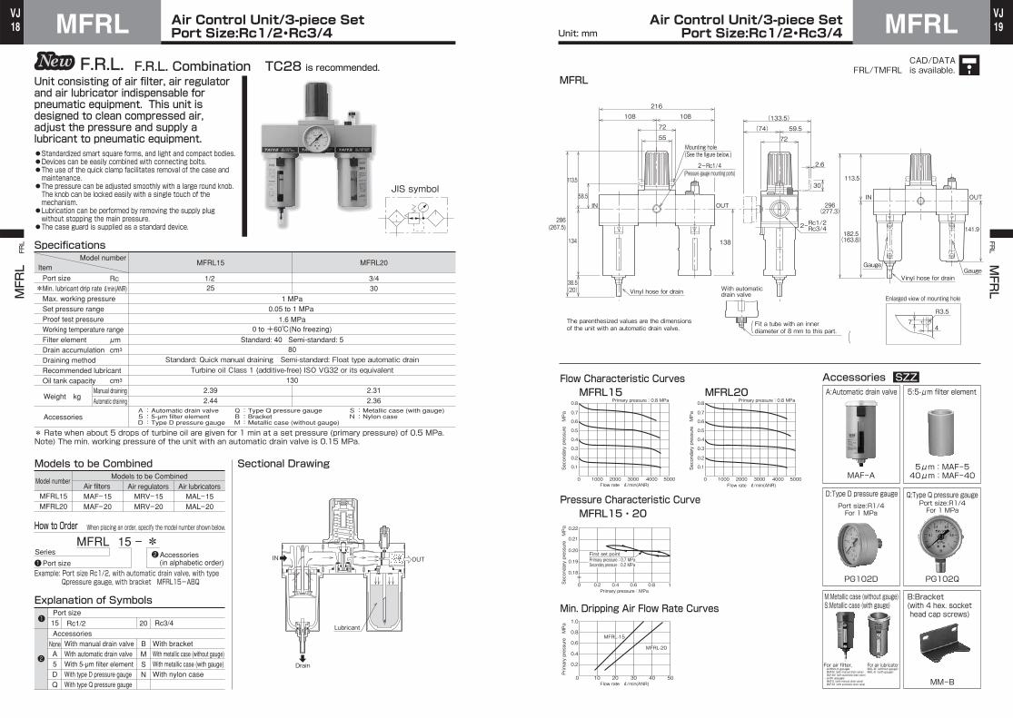
Port Size:Rc1/2・Rc3/4MFRL Air Control Unit/3-piece SetPort Size:Rc1/2・Rc3/4 MFRL
MFRL
FRL FR
L MFRL
Unit: mm
CAD/DATAis available.FRL/TMFRL
MFRL 15 - *
Example: Port size Rc1/2, with automatic drain valve, with type Qpressure gauge, with bracket MFRL15-ABQ
Port size
Accessories
15
A 5 D Q
B M S N
20 Rc3/4Rc1/2
With manual drain valveWith automatic drain valveWith 5-µm filter elementWith type D pressure gaugeWith type Q pressure gauge
With bracketWith metallic case (without gauge)With metallic case (with gauge)With nylon case
Sectional Drawing
1/2 3/425 30
S:Metallic case (with gauge)N:Nylon case
A:Automatic drain valve 5:5-µm filter element D:Type D pressure gauge
Q:Type Q pressure gauge B:Bracket M:Metallic case (without gauge)
MFRL15
2.392.44
2.312.36
MFRL20
1 MPa0.05 to 1 MPa
1.6 MPa
Standard: 40 Semi-standard: 580
Standard: Quick manual draining Semi-standard: Float type automatic drainTurbine oil Class 1 (additive-free) ISO VG32 or its equivalent
130
* Rate when about 5 drops of turbine oil are given for 1 min at a set pressure (primary pressure) of 0.5 MPa.Note) The min. working pressure of the unit with an automatic drain valve is 0.15 MPa.
MFRL15 MFRL20
MAF-15 MAF-20
MRV-15 MRV-20
Models to be CombinedModels to be Combined
MAL-15 MAL-20
Explanation of Symbols
JIS symbol
❶
❶❷
❷
F.R.L. Combination TC28 is recommended.F.R.L.
●Standardized smart square forms, and light and compact bodies.●Devices can be easily combined with connecting bolts.●The use of the quick clamp facilitates removal of the case and maintenance.
●The pressure can be adjusted smoothly with a large round knob.The knob can be locked easily with a single touch of the mechanism.
●Lubrication can be performed by removing the supply plug without stopping the main pressure.
●The case guard is supplied as a standard device.
Unit consisting of air filter, air regulator and air lubricator indispensable for pneumatic equipment. This unit is designed to clean compressed air, adjust the pressure and supply a lubricant to pneumatic equipment.
Model numberItem
Port sizeMin. lubricant drip rateMax. working pressureSet pressure rangeProof test pressureWorking temperature rangeFilter elementDrain accumulationDraining methodRecommended lubricantOil tank capacity
Rc ℓ/min(ANR)
μm cm3
cm3
*
Weight kg
Accessories
Manual draining
Automatic draining
Specifications
0 to +60℃(No freezing)
Model numberAir filters Air regulators Air lubricators
Series
Port sizeAccessories (in alphabetic order)
None
Lubricant
IN OUT
Drain
How to Order When placing an order, specify the model number shown below.
MFRL
58.5
134
113.5
38.5(20)
286(267.5)
138
OUTIN
55
72
108 108
216
30
(74)
72
59.5
2.6
(133.5)
74
R3.5
2ーRc1/2Rc3/4 141.9182.5(163.8)
113.5
296(277.3)
GaugeGauge
OUTIN
Enlarged view of mounting holeVinyl hose for drain
The parenthesized values are the dimensionsof the unit with an automatic drain valve.
2ーRc1/4(Pressure gauge mounting ports)
Mounting hole(See the figure below.)
With automaticdrain valve
Vinyl hose for drain
Secondary pressure MPa
Secondary pressure MPa
Secondary pressure MPa
Primary pressure MPa
Flow Characteristic CurvesMFRL15 MFRL20
Pressure Characteristic CurveMFRL15・20
Min. Dripping Air Flow Rate Curves
Accessories SZZA:Automatic drain valve
MAF-A
PG102D PG102Q
5:5-μm filter element
5μm:MAF-540μm:MAF-40
D:Type D pressure gauge Q:Type Q pressure gauge
B:Bracket (with 4 hex. sockethead cap screws)
MM-B
Port size:R1/4For 1 MPa
Port size:R1/4For 1 MPa
0.1
0 1000 2000 3000 4000 5000
0.2
0.3
0.4
0.5
0.6
0.7
0.8
Flow rate ℓ/min(ANR)
Flow rate ℓ/min(ANR)
Flow rate ℓ/min(ANR)
Primary pressure : 0.8 MPa Primary pressure : 0.8 MPa
0
0.18
0.19
0.20
0.21
0.22
0.2 0.4 0.6 0.8 1Primary pressure : MPa
0.1
0 1000 2000 3000 4000 5000
0.2
0.3
0.4
0.5
0.6
0.7
0.8
0.2
0 10 20 30 40 50
0.4
0.6
0.8
1.0
MFRL-15
MFRL-20
M:Metallic case (without gauge)S:Metallic case (with gauge)
For air filter,・without gauge MAF-M(with manual drain valve) MAF-AM(with automatic drain valve)・with gauge MAF-S(with manual drain valve) MAF-AS(with automatic drain valve)
For air lubricatorMAL-M(without gauge)MAL-S(with gauge)
First set pointPrimary pressure : 0.7 MPaSecondary pressure : 0.2 MPa
Fit a tube with an innerdiameter of 8 mm to this part.( (

20VJ
21VJAir Control Unit/3-piece Set
Port Size:Rc3/4・Rc1HFRL Air Control Unit/3-piece SetPort Size:Rc3/4・Rc1 HFRL
HFRL
FRL FR
L HFRL
Unit: mm
CAD/DATAis available.FRL/THFRL
HFRL 25 - *
Example: Port size Rc1, with automatic drain valve, with type Qpressure gauge, with bracket HFRL25-ABQ
Port size20
A 5
D Q B
25 Rc1Rc3/4
With manual drain valveWith automatic drain valveWith 5-µm filter element
With type D pressure gaugeWith type Q pressure gaugeWith bracket
Sectional Drawing
3/4 1
HFRL20 HFRL25
HAF-20 HAF-25
HRV-20 HRV-25
Models to be CombinedModels to be Combined
HAL-20 HAL-25
52LRFH02LRFH
851 MPa
0.05 to 0.9 MPa 1.6 MPa
Standard: 30 Semi-standard: 5500
Standard: Quick manual draining Semi-standard: Float type automatic drainTurbine oil Class 1 (additive-free) ISO VG32 or its equivalent
5005.7
5.75
*Rate when about 5 drops of turbine oil are given for 1 min at a set pressure (primary pressure) of 0.5 MPa.Note) The min. working pressure of the unit with an automatic drain valve is 0.15 MPa.
A:Automatic drain valve 5:5-µm filter element D:Type D pressure gauge
Q:Type Q pressure gauge B:Bracket
Explanation of Symbols
JIS symbol
❶
❶
❷
❷
F.R.L. Combination P3NCB is recommended.F.R.L.
●Standardized smart square forms, and light and compact bodies.●Devices can be easily combined with connecting bolts.●The use of the quick clamp facilitates removal of the case and maintenance.●Lubrication can be performed by removing the supply plug without stopping the main pressure.
Unit consisting of air filter, air regulator and air lubricator indispensable for pneumatic equipment. This unit is designed to clean compressed air, adjust the pressure and supply a lubricant to pneumatic equipment.
Model numberItem
Port sizeMin. lubricant drip rateMax. working pressureSet pressure rangeProof test pressureWorking temperature rangeFilter elementDrain accumulationDraining methodRecommended lubricantOil tank capacity
Rc ℓ/min(ANR)
μm cm3
cm3
*
Weight kg
Accessories
Manual draining
Automatic draining
Specifications
0 to +50℃(No freezing)
Model numberAir filters Air regulators Air lubricators
SeriesPort size
Accessories (in alphabetic order)
Accessories
None
Lubricant
IN OUT
Drain
How to Order When placing an order, specify the model number shown below.
HFRL
430(412)
293(275)
137
390
356
60 60135 135
90
36 60
55
195
With automatic drain valve
9
Sight glass
Vinyl hose for drain
Rc3/4Rc12ー
92
6
(81) 61
(142)
52
The parenthesized values are the dimensionsof the unit with an automatic drain valve.
Flow Characteristic CurvesHFRL20・25
HFRL20・25
Pressure Characteristic CurveHFRL20・25
Min. Dripping Air Flow Rate Curve
Accessories SZZA:Automatic drain valve
HAF-A
PG102D PG102Q
5:5-μm filter element
5μm:HAF-530μm:HAF-30
D:Type D pressure gauge Q:Type Q pressure gauge
B:Bracket (with 4 hex. socket head cap screws)
HO-B
Port size:R1/4For 1 MPa
Port size:R1/4For 1 MPa
0.1
0 2000 4000 6000 8000 10000
0.2
0.3
0.4
0.5
0.6
0.7
0.8
Flow rate ℓ/min(ANR)
Primary pressure : 0.8 MPa
0
0.18
0.19
0.20
0.21
0.22
0.2 0.4 0.6 0.8 1
Primary pressure : MPa
0.2
0 20 40 60 80 100 120 140
0.4
0.6
0.8
1
Flow rate ℓ/min(ANR)
2ーRc1/4 (Pressure gauge mounting ports)
Fit a tube with an innerdiameter of 8 mm to this part.( (
First set pointPrimary pressure : 0.7 MPaSecondary pressure : 0.2 MPa
Secondary pressure MPa
Primary pressure MPa
Secondary pressure MPa
22VJ
23VJFilter Regulators
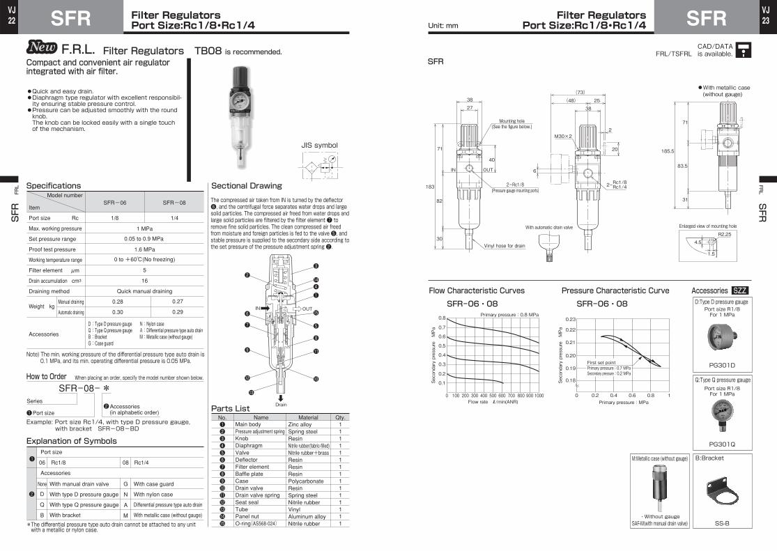
Port Size:Rc1/8・Rc1/4SFR Filter RegulatorsPort Size:Rc1/8・Rc1/4 SFR
SFR FRL FR
L SFR
Unit: mm
CAD/DATAis available.FRL/TSFRL
SFR-08- *
Example: Port size Rc1/4, with type D pressure gauge,with bracket SFR-08-BD
Port size
Accessories
06
D
Q
B
G
N
A
M
08 Rc1/4Rc1/8
Sectional Drawing
1/8 1/4Rc Port size
Max. working pressure
Set pressure range
Proof test pressure
Working temperature range
Filter element
Drain accumulation
Draining method
SFR-06 SFR-08
1 MPa
0.05 to 0.9 MPa
1.6 MPa
0 to +60℃(No freezing)
5
16
Quick manual draining
Note) The min. working pressure of the differential pressure type auto drain is0.1 MPa, and its min. operating differential pressure is 0.05 MPa.
0.28
0.30
0.27
0.29
D:Type D pressure gauge Q:Type Q pressure gauge B:Bracket G:Case guard
N:Nylon case A:Differential pressure type auto drainM:Metallic case (without gauge)
*The differential pressure type auto drain cannot be attached to any unitwith a metallic or nylon case.
Name Material Qty.111111111111111
No.
Parts List
Main bodyPressure adjustment springKnobDiaphragmValveDeflectorFilter elementBaffle plateCaseDrain valveDrain valve springSeat sealTubePanel nutO-ring(AS568-024)
Zinc alloySpring steelResinNitrile rubber(fabric-filled)Nitrile rubber+brassResinResinResinPolycarbonateResinSpring steelNitrile rubberVinylAluminum alloyNitrile rubber
Explanation of Symbols
With manual drain valve
With type D pressure gauge
With type Q pressure gauge
With bracket
With case guard
With nylon case
Differential pressure type auto drain
With metallic case (without gauge)
JIS symbol
❶
❶
❷
❷
❶❷❸❹❺❻❼❽❾101112131415
12
❾
❼
❻
❷❸
14❹❶
15
❺
❽
11
10
13
Filter Regulators TB08 is recommended.F.R.L.
●Quick and easy drain.●Diaphragm type regulator with excellent responsibil-ity ensuring stable pressure control.●Pressure can be adjusted smoothly with the round knob.The knob can be locked easily with a single touch of the mechanism.
Compact and convenient air regulator integrated with air filter.
SpecificationsModel number
Item
Weight kg
Accessories
Manual draining
Automatic draining
μm
cm3
IN OUT
DrainSeries
Port sizeAccessories (in alphabetic order)
None
The compressed air taken from IN is turned by the deflector ❻, and the centrifugal force separates water drops and large solid particles. The compressed air freed from water drops and large solid particles are filtered by the filter element ❼ to remove fine solid particles. The clean compressed air freed from moisture and foreign particles is fed to the valve ❺, and stable pressure is supplied to the secondary side according to the set pressure of the pressure adjustment spring ❷.
How to Order When placing an order, specify the model number shown below.
SFR
Flow Characteristic Curves
SFR-06・08 SFR-06・08
Pressure Characteristic Curve Accessories SZZ
PG301D
PG301Q
D:Type D pressure gauge
Q:Type Q pressure gauge
B:Bracket
SS-B
Port size R1/8For 1 MPa
Port size R1/8For 1 MPa
SAF-M(with manual drain valve)
M:Metallic case (without gauge)
・Without gauge
0.1
0 200 300100 400 500 600 700 800 900 1000
0.2
0.3
0.4
0.5
0.6
0.7
0.8
Flow rate ℓ/min(ANR)
Primary pressure : 0.8 MPa
0
0.18
0.19
0.20
0.21
0.23
0.2 0.4 0.6 0.8 1
0.22
Primary pressure : MPa
27
38
71
82
30
183
Vinyl hose for drain
40
IN OUT
38
2M30×2
(48) 25
(73)
20
6
71
83.5
31
185.5
4.5
1.5
R2.25
Enlarged view of mounting hole
Rc1/8Rc1/42ー
With automatic drain valve
2ーRc1/8(Pressure gauge mounting ports)
●With metallic case(without gauge)
Mounting hole(See the figure below.)
First set pointPrimary pressure : 0.7 MPaSecondary pressure : 0.2 MPa
Secondary pressure MPa
Secondary pressure MPa

24VJ
25VJFilter Regulators
Port Size:Rc1/4・Rc3/8・Rc1/2EFR Filter RegulatorsPort Size:Rc1/4・Rc3/8・Rc1/2 EFR
EFR FRL FR
L EFR
Unit: mm
CAD/DATAis available.FRL/TEFRL
EFR-10-*
Example: Port size Rc3/8, with automatic drain valve, with type Q pressure gauge, with bracket EFR-10-ABQ
08
A
B
D
Q
N
S
15 Rc1/2Rc1/4
10 Rc3/8
With manual drain valve
With automatic drain valve
With bracket
With type D pressure gauge
With type Q pressure gauge
With nylon case
With metallic case (with gauge)
Sectional Drawing
1/4 3/8 1/2
Specifications
A:Automatic drain valve D:Type D pressure gauge Q:Type Q pressure gauge
B:Bracket N:Nylon case S:Metallic case (with gauge)
EFR-08 EFR-10 EFR-15
0.62
0.64
0.61
0.63
0.60
0.62
1 MPa
0.05 to 1 MPa
1.6 MPa
0 to +60℃(No freezing)
5
60
Standard: Quick manual draining Semi-standard: Float type automatic drain
Note) The min. working pressure of the unit with an automaticdrain valve is 0.15 MPa.
Explanation of Symbols1111111111111
No.
Parts List
Main bodyPressure adjustment springKnobDiaphragmValveDeflectorFilter elementBaffle plateCaseCase guardVinyl tubeO-ring(S50)O-ring(S16)
Aluminum alloySpring steelResinNitrile rubber(fabric-filled)Nitrile rubber+brassResinResinResinPolycarbonateAluminum alloyVinylNitrile rubberNitrile rubber
Note)
JIS symbol
❶
❶
❷
❷
❸
❹
❺
❻
❽
11
❷
❶
12
❼
❾
10
13
❶❷❸❹❺❻❼❽❾10111213
Filter Regulators TB18 is recommended.F.R.L.
●Quick and easy drain.●Diaphragm type regulator with excellent responsibil-ity ensuring stable pressure control.●Pressure can be adjusted smoothly with the round knob.The knob can be locked easily with a single touch of the mechanism.●The use of the quick clamp facilitates removal of the case and maintenance.●The case guard is supplied as a standard device.
Compact and convenient air regulator integrated with air filter.
Rc Port size
Max. working pressure
Set pressure range
Proof test pressure
Working temperature range
Filter element
Drain accumulation
Draining method
Model number
Item
Weight kg
Accessories
Manual draining
Automatic draining
μm
cm3
Series
Port sizeAccessories (in alphabetic order)
Port size
Accessories
None
The compressed air taken from IN is turned by the deflector ❻, and the centrifugal force separates water drops and large solid particles from the compressed air. The compressed air freed from water drops and large solid particles are filtered by the filter element ❼ to remove fine solid particles. The compressed air freed from moisture and foreign particles is fed to the valve ❺, and stable pressure is supplied to the secondary side according to the set pressure of the pressure adjustment spring ❷.
Name Material Qty.
IN OUT
Drain
How to Order When placing an order, specify the model number shown below.
Note) When the unit is provided with the nylon case ,the O-ring is replaced with AS568-033.
N
EFR
Flow Characteristic CurvesEFR-08
EFR-08・10・15
EFR-10・15
Pressure Characteristic Curve
Accessories SZZA:Automatic drain valve
EAF-A
PG202D
EAF-S(with manual drain valve)EAF-AS(with automatic drain valve)
PG202Q
S:Metallic case (with gauge)
・With gauge
D:Type D pressure gauge Q:Type Q pressure gauge
B:Bracket Bracket
EE-B ES-B
Port size:R1/4For 1 MPa
Port size:R1/4For 1 MPa
0
0.10.20.30.40.50.60.70.8
400 800 1200 1600 2000
Flow rate ℓ/min(ANR)
Flow rate ℓ/min(ANR)
Primary pressure : 0.8 MPa
0
0.18
0.19
0.20
0.21
0.22
0.2 0.4 0.6 0.8 1Primary pressure : MPa
0
0.10.20.30.40.50.60.70.8
400 800 1200 1600 2000
Primary pressure : 0.8 MPa
6.510
R3.25
56
□63
78
100
26.5(18)
256(247.5)
33(22)
259.5(248.5)
129.5
IN OUT
With automaticdrain valve
55
34
(65.5) 56
2.6M42×2
(121.5)
25
100
126.5
Vinyl hose for drain
Enlarged view of mounting hole
Rc1/4Rc3/8Rc1/2
2ー
Fit a tube with an innerdiameter of 8 mm to this part.( (
2ーRc1/4(Pressure gauge mounting ports)
The parenthesized values are the dimensionsof the unit with an automatic drain valve.
Gauge
●With metallic case(with gauge)
Mounting hole(See the figure below.)
First set pointPrimary pressure : 0.7 MPaSecondary pressure : 0.2 MPa
Secondary pressure MPa
Secondary pressure MPa
Secondary pressure MPa

26VJ
27VJFilter Regulators
Port Size:Rc1/2・Rc3/4MFR Filter RegulatorsPort Size:Rc1/2・Rc3/4 MFR
MFR FRL FR
L MFR
Unit: mm
CAD/DATAis available.FRL/TMFRL
MFR-15-
Example: Port size Rc1/2, with automatic drain valve, with type Qpressure gauge, with bracket MFR-15-ABQ
Port size
Accessories
15
None
A
5
D
Q
B
M
S
N
20 Rc3/4Rc1/2
With manual drain valve
With automatic drain valve
With 5-µm filter element
With type D pressure gauge
With type Q pressure gauge
With bracket
With metallic case (without gauge)
With metallic case (with gauge)
With nylon case
Sectional Drawing
1/2 3/4
Specifications
1111111111111
No.
Parts List
MFR-15 MFR-20
1.12
1.17
1.10
1.15
1 MPa
0.05 to 1 MPa
1.6 MPa
0 to +60℃(No freezing)
Standard: 40 Semi-standard: 5
60
Standard: Quick manual draining Semi-standard: Float type automatic drain
Note) The min. working pressure of the unit with an automaticdrain valve is 0.15 MPa.
A:Automatic drain valve 5:5-µm filter elementD:Type D pressure gaugeQ:Type Q pressure gauge
B:Bracket M:Metallic case (without gauge)S:Metallic case (with gauge)N:Nylon case
Explanation of Symbols
JIS symbol
❶
❶
❸
❹❺
❻
❽
❷
❶
12
10❾
13
❶❷❸❹❺❻❼❽❾10111213
11
❼
Filter Regulators TB28 is recommended.F.R.L.
●Quick and easy drain.●Diaphragm type regulator with excellent responsibil-ity ensuring stable pressure control.●The pressure can be adjusted smoothly with a large round knob. The knob can be locked easily with a single touch of the mechanism.●The use of the quick clamp facilitates removal of the case and maintenance.●The case guard is supplied as a standard device.
Compact and convenient air regulator integrated with air filter.
*
Rc Port size
Max. working pressure
Set pressure range
Proof test pressure
Working temperature range
Filter element
Drain accumulation
Draining method
Model number
Item
Weight kg
Accessories
Manual draining
Automatic draining
μm
cm3
❷
❷
IN OUT
Drain
Series
Port sizeAccessories (in alphabetic order)
The compressed air taken from IN is turned by the deflector ❻, and the centrifugal force separates water drops and large solid particles from the compressed air. The compressed air freed from water drops and large solid particles are filtered by the filter element ❼ to remove fine solid particles. The compressed air freed from moisture and foreign particles is fed to the valve ❺, and stable pressure is supplied to the secondary side according to the set pressure of the pressure adjustment spring ❷.
Name Material Qty.Main bodyPressure adjustment springKnobDiaphragmValveDeflectorFilter elementBaffle plateCaseCase guardVinyl tubeO-ring(G55)O-ring(S16)
Aluminum alloySpring steelResinNitrile rubber (fabric-filled)Nitrile rubber+brassResinResinResinPolycarbonateAluminum alloyVinylNitrile rubberNitrile rubber
How to Order When placing an order, specify the model number shown below.
MFR
74
R3.5
Gauge
Vinyl hose for drain
Vinyl hose for drain
IN OUT 296(277.3)
182.5(163.8)
286(267.5)
38.5(20)
134
113.5
113.5
Rc1/2Rc3/4
38.5
72
2.6
(74) 59.5
(133.5)
30
55
72
IN OUT
58.5
Enlarged view of mounting hole
2ー
Flow Characteristic CurvesMFR-15
MFR-15・20
MFR-20
Pressure Characteristic Curve
Accessories SZZA:Automatic drain valve
MAF-A
PG102D PG102Q
D:Type D pressure gauge Q:Type Q pressure gauge
B:Bracket (with 4 hex. socket head cap screws)
MM-B
Port size:R1/4For 1 MPa
Port size:R1/4For 1 MPa
0.1
0 1000 2000 3000 4000 5000
0.2
0.3
0.4
0.5
0.6
0.7
0.8
Flow rate ℓ/min(ANR)
Primary pressure : 0.8 MPa
Primary pressure : 0.8 MPa
0
0.18
0.19
0.20
0.21
0.22
0.2 0.4 0.6 0.8 1Primary pressure : MPa
0.1
0 1000 2000 3000 4000 5000
0.2
0.3
0.4
0.5
0.6
0.7
0.8
5:5-μm filter element
5μm:MAF-540μm:MAF-40
Flow rate ℓ/min(ANR)
2ーRc1/4(Pressure gauge mounting ports)
Mounting hole(See the figure below.)
Fit a tube with an innerdiameter of 8 mm to this part.( (
The parenthesized values are the dimensionsof the unit with an automatic drain valve.
With automatic rain valve
First set pointPrimary pressure : 0.7 MPaSecondary pressure : 0.2 MPa ・Without gauge
MAF-M(with manual drain valve) MAF-MA(with automatic drain valve)・With gauge MAF-S(with manual drain valve) MAF-SA(with automatic drain valve)
●With metallic case(without gauge/with gauge)
Secondary pressure MPa
Secondary pressure MPa
Secondary pressure MPa
M:Metallic case (without gauge)S:Metallic case (with gauge)
28VJ
29VJ
SAF
FRL
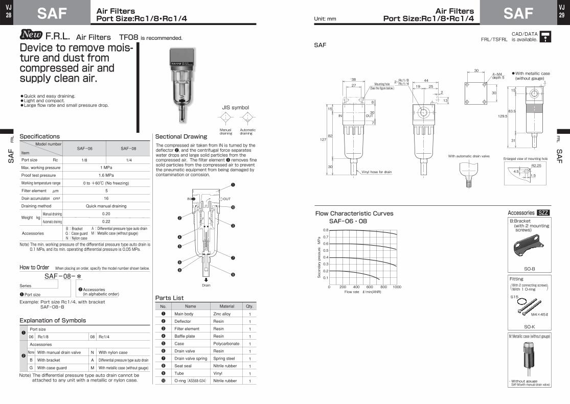
Air FiltersPort Size:Rc1/8・Rc1/4SAF Air Filters
Port Size:Rc1/8・Rc1/4 SAFFRL SAF
Unit: mm
CAD/DATAis available.FRL/TSFRL
SAF-08- Series
Example: Port size Rc1/4, with bracketSAF-08-B
06
B
G
N
A
M
08 Rc1/4Rc1/8
With manual drain valve
With bracket
With case guard
With nylon case
Differential pressure type auto drain
With metallic case (without gauge)
Sectional Drawing
1/8 1/4Rc
Max. working pressure
Proof test pressure
Working temperature range
Draining method
Accessories
Specifications
1
1
1
1
1
1
1
1
1
1
Parts List
Main body
Deflector
Filter element
Baffle plate
Case
Drain valve
Drain valve spring
Seat seal
Tube
O-ring (AS568-024)
Zinc alloy
Resin
Resin
Resin
Polycarbonate
Resin
Spring steel
Nitrile rubber
Vinyl
Nitrile rubber
B:Bracket G:Case guard N:Nylon case
A:Differential pressure type auto drain M:Metallic case (without gauge)
SAF-06 SAF-08
1 MPa
1.6 MPa
0 to +60℃ (No freezing)
5
16
Quick manual draining
0.20
0.22
Note) The min. working pressure of the differential pressure type auto drain is0.1 MPa, and its min. operating differential pressure is 0.05 MPa.
Note) The differential pressure type auto drain cannot beattached to any unit with a metallic or nylon case.
Explanation of Symbols
Automaticdraining
Manualdraining
JIS symbol
❶
❶
❷
❷
❸
❹
❺
❻
❽
❷
❶
❼
❾
10
❶
❷
❸
❹
❺
❻
❼
❽
❾
10
IN OUT
Drain
Air Filters TF08 is recommended.F.R.L.
●Quick and easy draining.●Light and compact.●Large flow rate and small pressure drop.
Port size
Model number
Item
Weight kgManual draining
Automatic draining
*
Port sizeAccessories (in alphabetic order)
Filter element
Drain accumulation
μm
cm3
Accessories
None
Port size
The compressed air taken from IN is turned by the deflector ❷, and the centrifugal force separates water drops and large solid particles from the compressed air. The filter element ❸ removes fine solid particles from the compressed air to prevent the pneumatic equipment from being damaged by contamination or corrosion.
No. Name Material Qty.
Device to remove mois-ture and dust from compressed air and supply clean air.
How to Order When placing an order, specify the model number shown below.
15
83.5129.5
31
30
302
19 25
44
13
Rc1/8Rc1/427
□38
30
8
7
OUTIN
Vinyl hose for drain
15
82
30
127
4.51.5
R2.25
Enlarged view of mounting hole
2ー
4ーM4depth 5
With automatic drain valve
・Without gauge SAF-M(with manual drain valve)
Flow Characteristic CurvesSAF-06・08
Accessories SZZ
Fitting
M:Metallic case (without gauge)
B:Bracket (with 2 mountingscrews)
SO-B
SO-K
0.1
0 200 400 600 800 1000
0.2
0.3
0.4
0.5
0.6
0.7
0.8
Secondary pressure MPa
With 2 connecting screwsWith 1 O-ring( )S15
M4×45ℓ
SAF
Mounting hole(See the figure below.)
●With metallic case(without gauge)
Flow rate ℓ/min(ANR)

30VJ
31VJAir Filters
Port Size:Rc1/4・Rc3/8・Rc1/2EAF Air FiltersPort Size:Rc1/4・Rc3/8・Rc1/2 EAF
EAF
FRL FR
L EAF
Unit: mm
CAD/DATAis available.FRL/TEFRL
JIS symbol
EAF-10-*
Example: Port size Rc3/8, with automatic drain valve,with bracket EAF-10-AB
Port size
Accessories
08
10
None
A
B
N
S
15 Rc1/2Rc1/4
Rc3/8
With manual drain valve
With automatic drain valve
With bracket
With nylon case
With metallic case (with gauge)
Sectional Drawing
1/4 1/23/8
Specifications
1
1
1
1
1
1
1
1
1
1
1
Parts List
A:Automatic drain valve B:Bracket
N:Nylon caseS:Metallic case (with gauge)
EAF-08 EAF-10 EAF-15
0.40
0.42
0.39
0.41
0.38
0.40
1 MPa
1.6 MPa
5
60
Standard: Quick manual draining Semi-standard: Float type automatic drain
Note) The min. working pressure of the unit with an automaticdrain valve is 0.15 MPa.
Explanation of Symbols
Note)
❷
❷
❶
❷
❸
❹
❺
❻
❼
❽
❾
10
11
❶
❷
❸
❹
❾
❽
11
❺
❻
❼
10
Rc
Max. working pressure
Proof test pressure
Working temperature range
Draining method
Accessories
0 to +60℃ (No freezing)
Port size
Model number
Item
Weight kgManual draining
Automatic draining
Filter element
Drain accumulation
μm
cm3
Series
Port sizeAccessories (in alphabetic order)
Automaticdraining
Manualdraining
The compressed air taken from IN is turned by the deflector ❷, and the centrifugal force separates water drops and large solid particles from the compressed air. The filter element ❸ removes fine solid particles from the compressed air to prevent the pneumatic equipment from being damaged by contamination or corrosion.
No. Name Material Qty.
Main body
Deflector
Filter element
Baffle plate
Case
Case guard
Drain valve
O-ring (S16)
Drain valve spring
Tube
O-ring (S50)
Aluminum alloy
Resin
Resin
Resin
Polycarbonate
Aluminum alloy
Resin
Nitrile rubber
Spring steel
Vinyl
Nitrile rubber
❶
❶
IN OUT
Drain
Air Filters TF18 is recommended.F.R.L.
●Quick and easy draining.●The use of the quick clamp facilitates removal of the case and maintenance.●The case guard is supplied as a standard device.
Device to remove mois-ture and dust from compressed air and supply clean air.
How to Order When placing an order, specify the model number shown below.
Note) When the unit is provided with the nylon case ,the O-ring is replaced with AS568-033.
N
22.5
129.5
26.5(18)
178.5(170)
22.5
126.5
33(22)
182(171)
56
45
22.5
□63
56
30
2.6
34
90
78
IN OUT
Enlarged view of mounting hole
Gauge
6.5
10R3.25
Rc1/4Rc3/8Rc1/2
2ー
Vinyl hosefor drain
With automaticdrain valve
Fit a tube with an innerdiameter of 8 mm to this part.( (
Vinyl hosefor drain
The parenthesized values are the dimensionsof the unit with an automatic drain valve.
Flow Characteristic CurvesEAF-08
EAF-10・15
Accessories SZZA:Automatic drain valve
EAF-A
B:Bracket(with 2 hex. socket head cap screws)
EO-B
0
0.10.20.30.40.50.60.70.8
400 800 1200 1600 2000
Secondary pressure MPa
Secondary pressure MPa
0
0.10.20.30.40.50.60.70.8
400 800 1200 1600 2000
Fitting
EO-K
With 2 hex. socket head cap screwsWith 1 special square seal( )
S:Metallic case(with gauge)
・With gauge EAF-S(with manual drain valve) EAF-AS(with automatic drain valve)
M6×60ℓ
EAF
Mounting hole(See the figure below.)
Flow rate ℓ/min(ANR)
Flow rate ℓ/min(ANR)
●With metallic case(with gauge)

32VJ
33VJAir Filters
Port Size:Rc1/2・Rc3/4MAF Air FiltersPort Size:Rc1/2・Rc3/4 MAF
MAF
FRL FR
L MAF
Unit: mm
CAD/DATAis available.FRL/TMFRL
JIS symbol
MAF-15-*
Example: Port size Rc1/2, with automatic drain valve,with bracket MAF-15-AB
15
A
5
B
M
S
N
20 Rc3/4Rc1/2
With manual drain valve
With automatic drain valve
With 5-μm filter element
With bracket
With metallic case (without gauge)
With metallic case (with gauge)
With nylon case
Sectional Drawing
1/2 3/4
1
1
1
1
1
1
1
1
1
1
1
1
Parts List
A:Automatic drain valve 5:5μm filter element B:Bracket
M:Metallic case (without gauge)S:Metallic case (with gauge)N:Nylon case
MAF-15 MAF-20
1 MPa
Standard: 40 Semi-standard: 5
Standard: Quick manual draining Semi-standard: Float type automatic drain
1.6 MPa
0 to +60℃ (No freezing)
80
0.65
0.71
0.63
0.68
Note) The min. working pressure of the unit with an automaticdrain valve is 0.15 MPa.
Explanation of Symbols
❶❷❸❹❺❻❼❽❾101112
❶
❷
❹
❺
❼
❽
12
❻❸
❾
11
10
IN OUT
Drain
Air Filters TF28 is recommended.F.R.L.
●Quick and easy drain.●The use of the quick clamp facilitates removal of the case and maintenance.●The case guard is supplied as a standard device.
Automaticdraining
Manualdraining
Rc
Max. working pressure
Proof test pressure
Working temperature range
Draining method
Accessories
Specifications
Port size
Model number
Item
Weight kgManual draining
Automatic draining
Filter element
Drain accumulation
μm
cm3
Series
Port sizeAccessories (in alphabetic order)
None
Accessories
Port size
No. Name Material Qty.
The compressed air taken from IN is turned by the deflector ❷, and the centrifugal force separates water drops and large solid particles from the compressed air. The filter element ❸ removes fine solid particles from the compressed air to prevent the pneumatic equipment from being damaged by contamination or corrosion.
Aluminum alloy
Resin
Polypropylene
Resin
Polycarbonate
Aluminum alloy
Resin
Resin
Nitrile rubber
Spring steel
Vinyl
Nitrile rubber
Main body
Deflector
Filter element
Baffle plate
Case
Case guard
Spring retainer
Drain valve
O-ring (S16)
Drain valve spring
Tube
O-ring (G55)
Device to remove mois-ture and dust from compressed air and supply clean air.
How to Order When placing an order, specify the model number shown below.
❶
❶
❷
❷
74
R3.5
IN OUT55
30
2.6
55
22
27.5
134
38.5(20)
200(181.5)
□72 38.5 59.5 39.5
98
27.5
182.5(163.8)
210(191.3)
Rc1/2Rc3/42ー
With automatic drain valve
Fit a tube with an innerdiameter of 8 mm to this part.( (
The parenthesized values are the dimensionsof the unit with an automatic drain valve.
Vinyl hosefor drain
Vinyl hose for drainEnlarged view of mounting hole
Gauge
With 2 hex. socket head cap screwsWith 1 special square seal
Flow Characteristic CurvesMAF-15
MAF-20
Accessories SZZA:Automatic drain valve
MAF-A
M:Metallic case (without gauge)S:Metallic case (with gauge)
5:5-μm filter element
5μm : MAF-540μm : MAF-40
0.1
0 1000 2000 3000 4000 5000
0.2
0.3
0.4
0.5
0.6
0.7
0.8
Secondary pressure MPa
Secondary pressure MPa
0.1
0 1000 2000 3000 4000 5000
0.2
0.3
0.4
0.5
0.6
0.7
0.8
B:Bracket(with 4 hex. sockethead cap screws)
MM-B
Fitting
MM-K
( (
M6×70ℓ
MAF
Mounting hole(See the figure below.)
●With metallic case(without gauge/with gauge)
Flow rate ℓ/min(ANR)
Flow rate ℓ/min(ANR)・Without gauge MAF-M(with manual drain valve) MAF-MA(with automatic drain valve)・With gauge MAF-S(with manual drain valve) MAF-SA(with automatic drain valve)

34VJ
35VJAir Filters
Port Size:Rc3/4・Rc1HAF Air FiltersPort Size:Rc3/4・Rc1 HAF
HAF
FRL FR
L HAF
Unit: mm
CAD/DATAis available.FRL/THFRL
JIS symbol
HAF-25-
Example: Port size Rc1, with automatic drain valve,with bracket HAF-25-AB
Port size
Accessories
20
None
A
5
B
25 Rc1Rc3/4
With manual drain valve
With automatic drain valve
With 5-μm filter element
With bracket
Sectional Drawing
13/4
1
1
1
1
1
1
1
1
1
1
1
Parts List
IN OUT
Drain
HAF-20 HAF-25
1 MPa
1.6 MPa
500
Standard: Quick manual draining Semi-standard: Float type automatic drain
2.2
2.25
A:Automatic drain valve 5:5-µm filter element B:Bracket
Note) The min. working pressure of the unit with an automaticdrain valve is 0.15 MPa.
Explanation of Symbols
❶❷❸❹❺❻❼❽❾1011
❶
❶
❷
❷
❶
❸
❹
❽
❾
❷
10
❺
❻11❼
*
Air Filters P3NFA is recommended.F.R.L.
●Quick and easy draining.●Pressure drop is small even at a large flow rate.●The use of the quick clamp facilitates removal of the case and maintenance.
Device to remove mois-ture and dust from compressed air and supply clean air.
Rc
Max. working pressure
Proof test pressure
Working temperature range
Draining method
Accessories
Specifications
Port size
Model number
Item
Weight kgManual draining
Automatic draining
Filter element
Drain accumulation
μm
cm3
0 to +50℃ (No freezing)
Standard: 30 Semi-standard: 5
Series
Port sizeAccessories (in alphabetic order)
Automaticdraining
Manualdraining
The compressed air taken from IN is turned by the louver ❷, and the centrifugal force separates water drops and large solid particles from the compressed air. The filter element ❸ removes fine solid particles from the compressed air to prevent the pneumatic equipment from being damaged by contamination or corrosion.
No. Name Material Qty.
Main body
Louver
Filter element
Baffle plate
Case
Spring retainer
Drain valve
Drain valve spring
Tube
O-ring (inner dia. 78×wire dia. 4)
O-ring (S16)
Aluminum alloy
Resin
Resin
Resin
Zinc alloy
Resin
Resin
Spring steel
Vinyl
Nitrile rubber
Nitrile rubber
How to Order When placing an order, specify the model number shown below.
HAF
90
176
210
36 60
9
323(305)293
(275)
30IN OUT
Sight glass
Vinyl hose for drain
Rc3/4Rc1
692
52 61
113
2ー
With 2 hex. socket head cap screwsWith 1 O-ring
Flow Characteristic CurvesHAF-20・25
Accessories SZZA:Automatic drain valve
HAF-A
5:5-μm filter element
5μm:HAF-530μm:HAF-30
B:Bracket(with 4 hex. sockethead cap screws)
HO-B
Fitting
HO-K
( (
0.1
0 2000 4000 6000 8000 10000
0.2
0.3
0.4
0.5
0.6
0.7
0.8
Secondary pressure MPa
G35
M8×85ℓ
Fit a tube with an innerdiameter of 8 mm to this part.( (
With automaticdrain valve
The parenthesized values are the dimensionsof the unit with an automatic drain valve.
Flow rate ℓ/min(ANR)

36VJ
37VJAir Regulators
Port Size:Rc1/8・Rc1/4SRV・SRC Air RegulatorsPort Size:Rc1/8・Rc1/4 SRV・SRC
SRV・SRC FRL FR
L SRV・SRC
Unit: mm
CAD/DATAis available.FRL/TSFRL
JIS symbol
SRV-08-*
Port size
Accessories
06
D
Q
B
08 Rc1/4Rc1/8
With type D pressure gauge
With type Q pressure gauge
With bracket
Sectional Drawings
1/8 1/4Rc
kg
Port size
Max. working pressure
Set pressure range
Proof test pressure
Working temperature range
Weight
Accessories
Specifications
1111111
Parts List
Main bodyPressure adjustment springKnobDiaphragmValveCheck valve assemblyPanel nut
Zinc alloySpring steelResinNitrile rubber (fabric-filled)Nitrile rubber+brass
Aluminum alloy
SRV-06SRC-06(with check valve) (with check valve)
SRV-08SRC-08
1 MPa
0.05 to 0.9 MPa
1.6 MPa
0.23
D:Type D pressure gauge Q:Type Q pressure gauge B:Bracket
SeriesSRV:Air regulator SRC:Regulator with check valve
Example: Air regulator, port size Rc1/4, with type Dpressure gauge, with bracket SRV-08-BD
Air Regulators
Explanation of Symbols❶❷❸❹❺❻❼
❶
❶
❷
❷
❷
❹
❺
❸
❼
❶
❷
❹
❺
❻ ❻
❷
❺
Model number
Item
0 to +60℃ (No freezing)
Port sizeAccessories (in alphabetic order)
How to Order When placing an order, specify the model number shown below.
IN OUT IN OUT
●When operating ●When relieving
OUT
Fig. 1
INside
INside
INsideOUT OUT
Regulators with check valve
Air Regulators TR08 is recommended.F.R.L.
●Diaphragm type regulator with excellent responsibil-ity ensuring stable pressure control.●Pressure can be adjusted smoothly with the round knob.The knob can be locked easily with a single touch of the mechanism.●Regulators with check valve are available.[SRC-06(Rc1/8)・SRC-08(Rc1/4)]
Adjustment of com-pressed air pressure to obtain stable pressure.
●When operating The compressed air taken from IN is fed to the valve ❺ to supply stable pressure to the secondary side according to the set pressure of the pressure adjustment spring ❷.
●When relievingWhen the secondary pressure exceeds the set pressure of the pressure adjustment spring ❷, the diaphragm ❹ is pushed up to close the valve ❺.Simultaneously, the secondary pressure is released to atmosphere through the relief port, the secondary pressure is balanced with the set pressure of the pressure adjustment spring ❷, and the regulator returns to the regular operating state.
●When operatingWhen compressed air is fed from the IN side, the check valve ❻ is closed, and the set pressure is supplied to the secondary side in the same manner as an ordinary regulator. (Fig. 1)
●When discharging●When the directional control valve is switched, the compressed air on the IN side is discharged. Simultaneously, the check valve ❻ opens to discharge the compressed air from the diaphragm chamber, and the pressure in the diaphragm chamber is reduced below the set pressure. (Fig. 2)●When the pressure in the diaphragm chamber is reduced, the pressure adjustment spring ❷ pushes down the diaphragm to open the valve ❺, and the compressed air on the OUT side is discharged to the IN side. (Fig. 3)
Fig. 2 Fig. 3Diaphragmchamber
No. Name Material Qty.
—
4.51.5
R2.25
40
4
1571
19
90
27
38
1020
6
6
38
2
(48) 25
(73)
Panel nut
IN OUT
2ーRc1/8(Pressure gauge mounting ports)
M30×2
Enlarged view of mounting hole
Rc1/8Rc1/42ー
Mounting hole(See the figure below.)
Flow Characteristic CurvesSRV-06・08 SRV-06・08
Pressure Characteristic Curve Accessories SZZ
PG301D
PG301Q
D:Type D pressure gauge
Q:Type Q pressure gauge
B:Bracket
SS-B
Port size:R1/8For 1 MPa
Port size:R1/8For 1 MPa
0.1
0 200 400 600 800 1000
0.2
0.3
0.4
0.5
0.6
0.7
0.8
Secondary pressure MPa
Secondary pressure MPa
Flow rate ℓ/min(ANR)
Primary pressure:0.8 MPa
0
0.18
0.19
0.20
0.21
0.22
0.23
0.2 0.4 0.6 0.8 1
First set pointPrimary pressure:0.7 MPaSecondary pressure:0.2 MPa
Primary pressure:MPa
SRV・SRC

38VJ
39VJAir Regulator for Low Pressure
Port Size:Rc1/8・Rc1/4SRV・SRC Air Regulator for Low PressurePort Size:Rc1/8・Rc1/4 SRV・SRC
SRV・SRC FRL FR
L SRV・SRC
Unit: mm
CAD/DATAis available.FRL/TSFRL
With check valve
SRV-08-4L-*
Port size
Accessories
06
D
Q
B
08 Rc1/4Rc1/8
L4L2 Max. set pressure 0.2 MPa Max. set pressure 0.4 MPa
With type D pressure gauge (0 to 0.4 MPa)
With type Q pressure gauge (0 to 0.4 MPa)
With bracket
Sectional Drawings
1/8 1/4
Set pressure range
kg
Proof test pressure
Working temperature range
Weight
Accessories
RcPort size
Max. working pressure
1111111
Parts List
Main bodyPressure adjustment springKnobDiaphragmValveCheck valve assemblyPanel nut
Zinc alloySpring steelResinNitrile rubber (fabric-filled)Nitrile rubber+brass
Aluminum alloy
Example: Air regulator, port size Rc1/4, pressure setting level 0.4 MPa, with type D pressure gauge, with bracket SRV-08-4L-BD
SRV-06-2L・4LSRC-06-2L・4L (with check valve) (with check valve)
SRV-08-2L・4LSRC-08-2L・4L
1.6 MPa
0.23
D:Type D pressure gauge (0 to 0.4 MPa)Q:Type Q pressure gauge (0 to 0.4 MPa)B:Bracket
Pressure setting level
1 MPa
2L:0.05 to 0.2 MPa4L:0.05 to 0.4 MPa
Explanation of Symbols
❶❷
❶
❷
❸
❶❷❸❹❺❻❼
❷
❹
❺
❸
❼
❶
❷
❹
❺IN OUT IN OUT
OUT OUT OUT
❻ ❻
❷
❺
Air Regulators TR08 is recommended.F.R.L.
●Diaphragm type regulator with excellent responsibil-ity ensuring stable pressure control.●Pressure can be adjusted smoothly with the round knob.The knob can be locked easily with a single touch of the mechanism.●Low-pressure regulators with check valve are available.
Adjustment of com-pressed air pressure to obtain stable pressure.
SRC-06-2L(Rc1/8)・SRC-08-2L(Rc1/4)SRC-06-4L(Rc1/8)・SRC-08-4L(Rc1/4)][
SpecificationsModel number
Item
0 to +60℃ (No freezing)
SeriesSRV:Air regulator SRC:Regulator with check valve
Port size
Pressure setting level
Accessories (in alphabetic order)
No. Name Material Qty.
—
JIS symbol
Air Regulators
Regulators with check valve
●When operating ●When relieving
Fig. 1 Fig. 2 Fig. 3Diaphragmchamber
INside
INside
INside
●When operatingThe compressed air taken from IN is fed to the valve ❺ to supply stable pressure to the secondary side according to the set pressure of the pressure adjustment spring ❷.
●When relievingWhen the secondary pressure exceeds the set pressure of the pressure adjustment spring ❷, the diaphragm ❹ is pushed up to close the valve ❺.Simultaneously, the secondary pressure is released to atmosphere through the relief port, the secondary pressure is balanced with the set pressure of the pressure adjustment spring ❷, and the regulator returns to the regular operating state.
●When operatingWhen compressed air is fed from the IN side, the check valve ❻ is closed, and the set pressure is supplied to the secondary side in the same manner as an ordinary regulator. (Fig. 1)
●When discharging●When the directional control valve is switched, the compressed air on the IN side is discharged. Simultaneously, the check valve ❻ opens to discharge the compressed air from the diaphragm chamber, and the pressure in the diaphragm chamber is reduced below the set pressure. (Fig. 2)●When the pressure in the diaphragm chamber is reduced, the pressure adjustment spring ❷ pushes down the diaphragm to open the valve ❺, and the compressed air on the OUT side is discharged to the IN side. (Fig. 3)
How to Order When placing an order, specify the model number shown below.
❸
4.51.5
R2.25
40
4
1571
19
90
27
38
1020
6
6
38
2
(55) 25
(80)
Panel nut
IN OUT
Rc1/8Rc1/4
2ーRc1/8(Pressure gauge mounting ports)
M30×2
Enlarged view of mounting hole
2ー
Mounting hole(See the figure below.)
Flow Characteristic CurvesSRV-06・08-2L
SRV-06・08-4L
SRV-06・08Pressure Characteristic Curve Accessories SZZ
D:Type D pressure gauge
Q:Type Q pressure gauge
B:Bracket
SS-B
Port size:R1/8
Port size:R1/80
0.18
0.19
0.20
0.21
0.22
0.23
0.2 0.4 0.6 0.8 1
Secondary pressure MPa
Secondary pressure MPa
Secondary pressure MPa
First set pointPrimary pressure:0.7 MPaSecondary pressure:0.2 MPa
Primary pressure:MPa0
0.15
0.10
0.05
0.20
250 500 750 1000 1250
Primary pressure:0.4 MPa
0
0.30
0.25
0.20
0.15
0.10
0.05
0.40
0.35
250 500 750 1000 1250
Primary pressure:0.7 MPaThe flow characteristic curves and pressure characteristic curves of SRC Series regulators with check valve are the same as those of SRV Series.
PG301DL(0 to 0.4MPa)
PG301QL(0 to 0.4MPa)
Flow rate ℓ/min(ANR)
Flow rate ℓ/min(ANR)
SRV・SRC

40VJ
41VJAir Regulators
Port Size:Rc1/4・Rc3/8・Rc1/2ERV・ERC Air RegulatorsPort Size:Rc1/4・Rc3/8・Rc1/2 ERV・ERC
ERV・ERC FRL FR
L ERV・ER
CUnit: mm
CAD/DATAis available.FRL/TEFRL
ERV-10-*
Port size
Accessories
08
10
D
Q
B
15 Rc1/2Rc1/4
Rc3/8
1/4 3/8 1/2
Specifications
111111
Parts List
Main bodyPressure adjustment springKnobDiaphragmValveCheck valve assembly
Aluminum alloySpring steelResinNitrile rubber (fabric-filled)Nitrile rubber+brass
-
Example: Air regulator, port size Rc3/8, with type Q pressuregauge, with bracket ERV-10-BQ
ERV-08ERC-08(with check valve)
ERV-10ERC-10(with check valve)
ERV-15ERC-15(with check valve)
1 MPa
0.05 to 1 MPa
1.6 MPa
0 to +60℃(No freezing)
0.50
D:Type D pressure gauge Q:Type Q pressure gauge B:Bracket
94.015.0
Explanation of Symbols
❸
❶
❷
❹
❺
❻ ❻
❷
❺
❶❷❸❹❺❻
❶
❶
❷
❷
SeriesERV:Air regulator ERC:Regulator with check valve
Port sizeAccessories (in alphabetic order)
With type D pressure gauge
With type Q pressure gauge
With bracket
JIS symbol
Sectional Drawings
No. Name Material Qty.
●When operatingThe compressed air taken from IN is fed to the valve ❺ to supply stable pressure to the secondary side according to the set pressure of the pressure adjustment spring ❷.
●When relievingWhen the secondary pressure exceeds the set pressure of the pressure adjustment spring ❷, the diaphragm ❹ is pushed up to close the valve ❺.Simultaneously, the secondary pressure is released to atmosphere through the relief port, the secondary pressure is balanced with the set pressure of the pressure adjustment spring ❷, and the regulator returns to the regular operating state.
●When operatingWhen compressed air is fed from the IN side, the check valve ❻ is closed, and the set pressure is supplied to the secondary side in the same manner as an ordinary regulator. (Fig. 1)●When discharging ●When the directional control valve is switched, the compressed air on the
IN side is discharged. Simultaneously, the check valve ❻ opens to discharge the compressed air in the diaphragm chamber to the IN side, and the pressure in the diaphragm chamber is reduced below the set pressure. (Fig. 2)
●When the pressure in the diaphragm chamber is reduced, the pressure adjustment spring ❷ pushes down the diaphragm to open the valve ❺, and the compressed air on the OUT side is discharged to the IN side. (Fig. 3)
IN INOUT OUT
OUT OUT OUT
Rc
kg
Port size
Max. working pressure
Set pressure range
Proof test pressure
Working temperature range
Weight
Accessories
Model number
Item
Air Regulators TR18 is recommended.F.R.L.
●Diaphragm type regulator with excellent responsibil-ity ensuring stable pressure control.●Pressure can be adjusted smoothly with the round knob.The knob can be locked easily with a single touch of the mechanism.●Regulators with check valve are available.
Adjustment of com-pressed air pressure to obtain stable pressure.
ERC-08(Rc1/4)・SRC-10(Rc3/8)ERC-15(Rc1/2) ][
Air Regulators
Regulators with check valve
●When operating ●When relieving
Fig. 1 Fig. 2 Fig. 3Diaphragmchamber
INside
INside
INside
How to Order When placing an order, specify the model number shown below.
With check valve
Flow Characteristic CurvesERV-08 ERV-08・10・15
ERV-10・15
Pressure Characteristic Curve Accessories SZZD:Type D pressure gauge Q:Type Q pressure gauge
B:Bracket
EE-B
Port size:R1/4 For 1 MPa
Port size:R1/4 For 1 MPa
Bracket
ES-B
PG202D PG202Q
0
0.1
0.2
0.3
0.4
0.5
0.6
0.7
0.8
400 800 1200 1600 2000
0 400 800 1200 1600 2000
Secondary pressure MPa
Secondary pressure MPa
Secondary pressure MPa
Flow rate ℓ/min(ANR)
Flow rate ℓ/min(ANR)
Primary pressure : 0.8 MPa
Primary pressure : 0.8 MPa
0.18
0.19
0.20
0.21
0.22
0.6 0.8 10.40.20
First set point Primary pressure : 0.7 MPa Secondary pressure : 0.2 MPa
Primary pressure : MPa
0.1
0.2
0.3
0.4
0.5
0.6
0.7
0.8 The flow characteristic curves and pressure characteristic curves of ERC Series regulators with check valve are the same as those of ERV Series.
25
2.6
6.5 10
R3.25
2ーRc1/4(Pressure gauge mounting ports)
Rc1/42ーRc3/8Rc1/2
M42×2
Panel nut
22.5
122.5100
IN OUT
55
56
□63
78
820
(65.5) 56
(121.5)
Enlarged view of mounting hole
ERV・ERC
Mounting hole(See the figure below.)
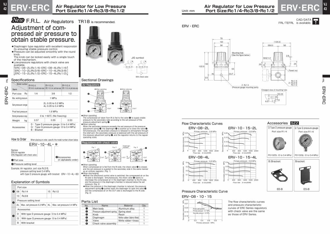
42VJ
43VJAir Regulator for Low Pressure
Port Size:Rc1/4・Rc3/8・Rc1/2ERV・ERC Air Regulator for Low PressurePort Size:Rc1/4・Rc3/8・Rc1/2 ERV・ERC
ERV・ERC FRL FR
L ERV・ER
CUnit: mm
CAD/DATAis available.FRL/TEFRL
Sectional Drawings
●When operating ●When relieving
1/4 1/23/8
Specifications
111111
Parts List
Main bodyPressure adjustment springKnobDiaphragmValveCheck valve assembly
Aluminum alloySpring steelResinNitrile rubber (fabric-filled)Nitrile rubber+brass
-
ERV-08-2L・4LERC-08-2L・4L (with check valve) (with check valve) (with check valve)
ERV-10-2L・4LERC-10-2L・4L
ERV-15-2L・4LERC-15-2L・4L
1.6 MPa
0.55 0.530.57
1 MPa
2L:0.05 to 0.2 MPa 4L:0.05 to 0.4 MPa
ERV-10-4L-*
Port size
Accessories
08
10
15 Rc1/2Rc1/4
Rc3/8
L4L2 Max. set pressure 0.2 MPa Max. set pressure 0.4 MPa
Example: Air regulator, port size Rc3/8,pressure setting level 0.4 MPa, with type D pressure gauge, with bracket ERV-10-4L-BD
Pressure setting level
D
Q
B
With type D pressure gauge (0 to 0.4 MPa)
With type Q pressure gauge (0 to 0.4 MPa)
With bracket
D:Type D pressure gauge (0 to 0.4 MPa) Q:Type Q pressure gauge (0 to 0.4 MPa) B:Bracket
Explanation of Symbols
❶❷❸❹❺❻
❷
❹
❺
❸
❶
❻ ❻
❷
❺❶❷
❶
❷
❸
IN INOUT OUT
OUT OUT OUT
Set pressure range
kg
Proof test pressure
Working temperature range
Weight
Accessories
RcPort size
Max. working pressure
Model number
Item
Air Regulators TR18 is recommended.F.R.L.
●Diaphragm type regulator with excellent responsibil-ity ensuring stable pressure control.●Pressure can be adjusted smoothly with the round knob.The knob can be locked easily with a single touch of the mechanism.●Low-pressure regulators with check valve are available.
Adjustment of com-pressed air pressure to obtain stable pressure.
ERC-08-2L(Rc1/4)・ERC-08-4L(Rc1/4)ERC-10-2L(Rc3/8)・ERC-10-4L(Rc3/8)ERC-15-2L(Rc1/2)・ERC-15-4L(Rc1/2)][
0 to +60℃ (No freezing)
SeriesERV:Air regulator ERC:Regulator with check valve
Port size
Pressure setting level
Accessories (in alphabetic order)
Air Regulators
Regulators with check valve
Fig. 1 Fig. 2 Fig. 3Diaphragmchamber
INside
INside
INside
No. Name Material Qty.
●When operatingThe compressed air taken from IN is fed to the valve ❺ to supply stable pressure to the secondary side according to the set pressure of the pressure adjustment spring ❷.
●When relievingWhen the secondary pressure exceeds the set pressure of the pressure adjustment spring ❷, the diaphragm ❹ is pushed up to close the valve ❺.Simultaneously, the secondary pressure is released to atmosphere through the relief port, the secondary pressure is balanced with the set pressure of the pressure adjustment spring ❷, and the regulator returns to the regular operating state.
●When operatingWhen compressed air is fed from the IN side, the check valve ❻ is closed, and the set pressure is supplied to the secondary side in the same manner as an ordinary regulator. (Fig. 1)●When discharging ●When the directional control valve is switched, the compressed air on the
IN side is discharged. Simultaneously, the check valve ❻ opens to discharge the compressed air in the diaphragm chamber to the IN side, and the pressure in the diaphragm chamber is reduced below the set pressure. (Fig. 2)
●When the pressure in the diaphragm chamber is reduced, the pressure adjustment spring ❷ pushes down the diaphragm to open the valve ❺, and the compressed air on the OUT side is discharged to the IN side. (Fig. 3)
JIS symbol
With check valve
How to Order When placing an order, specify the model number shown below.
❸
25
2.6
6.510
R3.25
M42×2
Panel nut
Enlarged view of mounting hole
Flow Characteristic CurvesERV-08-2L
ERV-08・10・15
ERV-10・15-2L
ERV-08-4L ERV-10・15-4L
Pressure Characteristic Curve
Accessories SZZD:Type D pressure gauge Q:Type Q pressure gauge
B:Bracket
EE-B
Port size:R1/4 Port size:R1/4
Bracket
ES-B
PG102DL (0 to 0.4 MPa) PG102QL (0 to 0.4 MPa)
0.05
0.10
0.15
0.20
0 400 800 1200 1600 2000
Primary pressure:0.8 MPa
Secondary pressure MPa
Secondary pressure MPa
Secondary pressure MPa
Secondary pressure MPa
Secondary pressure MPa
0
0.18
0.19
0.20
0.21
0.22
0.2 0.4 0.6 0.8 1Primary pressure : MPa
0.05
0.10
0.15
0.20
0 400 800 1200 1600 2000
Primary pressure:0.8 MPa
0
0.1
0.2
0.3
0.4
400 800 1200 1600 2000
Primary pressure:0.8 MPa
0
0.1
0.2
0.3
0.4
400 800 1200 1600 2000
Flow rate ℓ/min(ANR) Flow rate ℓ/min(ANR)
Flow rate ℓ/min(ANR)Flow rate ℓ/min(ANR)
Primary pressure:0.8 MPa
22.5
122.5100
IN OUT
55
56
□63
78
820
(69.5) 56
(125.5)
Rc1/42ーRc3/8Rc1/22ーRc1/4
(Pressure gauge mounting ports)
Mounting hole(See the figure below.)
The flow characteristic curves and pressure characteristic curves of ERC Series regulators with check valve are the same as those of ERV Series.
First set pointPrimary pressure:0.7 MPaSecondary pressure:0.2 MPa
ERV・ERC

44VJ
45VJAir Regulators
Port Size:Rc1/2・Rc3/4MRV・MRC Air RegulatorsPort Size:Rc1/2・Rc3/4 MRV・MRC
MRV・MRC FRL FR
L MRV・M
RC
Unit: mm
CAD/DATAis available.FRL/TMFRL
OUT OUT OUT
MRV-15-*
Port size
Accessories
15
D
Q
B
20 Rc3/4Rc1/2
With type D pressure gauge
With type Q pressure gauge
With bracket
Sectional Drawings
Rc
kg
Port size
Max. working pressure
Set pressure range
Proof test pressure
Working temperature range
Weight
Accessories
Specifications
111111
Parts List
Main bodyPressure adjustment springKnobDiaphragmValveCheck valve assembly
Aluminum alloySpring steelResinNitrile rubber (fabric-filled)Nitrile rubber+brass
-
Example: Air regulator, port size Rc1/2, with type Q pressuregauge, with bracket MRV-15-BQ
MRV-15MRC-15(with check valve) (with check valve)
MRV-20MRC-20
1.0 0.97
1 MPa
0.05 to 1 MPa
1.6 MPa
D:Type D pressure gauge Q:Type Q pressure gauge B:Bracket
IN OUT IN OUT
Explanation of Symbols
❶❷❸❹❺❻
❷
❹
❸
❶
❺
❷
❺
❻❻
❷
❷
❶
❶
Air Regulators TR28 is recommended.F.R.L.
●Diaphragm type regulator with excellent responsibil-ity ensuring stable pressure control.●The pressure can be adjusted smoothly with a large round knob. The knob can be locked easily with a single touch of the mechanism.●Regulators with check valve are available.[MRC-15(Rc1/2)・MRC-20(Rc3/4)]
Adjustment of com-pressed air pressure to obtain stable pressure.
Model number
Item
1/2 3/4
0 to +60℃ (No freezing)
SeriesMRV:Air regulator MRC:Regulator with check valve
Port sizeAccessories (in alphabetic order)
JIS symbol
Air Regulators
Regulators with check valve
●When operating ●When relieving
Fig. 1 Fig. 2 Fig. 3Diaphragmchamber
INside
INside
INside
No. Name Material Qty.
●When operatingThe compressed air taken from IN is fed to the valve ❺ to supply stable pressure to the secondary side according to the set pressure of the pressure adjustment spring ❷.
●When relievingWhen the secondary pressure exceeds the set pressure of the pressure adjustment spring ❷, the diaphragm ❹ is pushed up to close the valve ❺.Simultaneously, the secondary pressure is released to atmosphere through the relief port, the secondary pressure is balanced with the set pressure of the pressure adjustment spring ❷, and the regulator returns to the regular operating state.
●When operatingWhen compressed air is fed from the IN side, the check valve ❻ is closed, and the set pressure is supplied to the secondary side in the same manner as an ordinary regulator. (Fig. 1)
●When discharging ●When the directional control valve is switched, the compressed air on the
IN side is discharged. Simultaneously, the check valve ❻ opens to discharge the compressed air in the diaphragm chamber to the IN side, and the pressure in the diaphragm chamber is reduced below the set pressure. (Fig. 2)
●When the pressure in the diaphragm chamber is reduced, the pressure adjustment spring ❷ pushes down the diaphragm to open the valve ❺, and the compressed air on the OUT side is discharged to the IN side. (Fig. 3)
With check valve
How to Order When placing an order, specify the model number shown below.
30
2.6
74
R3.5
Rc1/2Rc3/42ー
Flow Characteristic CurvesMRV-15
MRV-20
MRV-15・20Pressure Characteristic Curve Accessories SZZ
PG102D
PG102Q
D:Type D pressure gauge
Q:Type Q pressure gauge
B:Bracket(with 4 hex. sockethead cap screws)
MM-B
Port size:R1/4For 1 MPa
Port size:R1/4For 1 MPa
0.1
0 1000 2000 3000 4000 5000
0.2
0.3
0.4
0.5
0.6
0.7
0.8
Secondary pressure MPa
Secondary pressure MPa
Secondary pressure MPa
Flow rate ℓ/min(ANR)
Flow rate ℓ/min(ANR)
Primary pressure : 0.8 MPa
0
0.18
0.19
0.20
0.21
0.22
0.2 0.4 0.6 0.8 1Primary pressure : MPa
0.1
0 1000 2000 3000 4000 5000
0.2
0.3
0.4
0.5
0.6
0.7
0.8 Primary pressure : 0.8 MPa
OUT
58.5
27.5
141
IN
113.5
55
7272
(74) 59.5
(133.5)
Enlarged view of mounting hole2ーRc1/4(Pressure gauge mounting ports)
Mounting hole(See the figure below.)
First set pointPrimary pressure:0.7 MPaSecondary pressure:0.2 MPa
MRV・MRC

46VJ
47VJAir Regulator for Low Pressure
Port Size:Rc1/2・Rc3/4MRV・MRC Air Regulator for Low PressurePort Size:Rc1/2・Rc3/4 MRV・MRC
MRV・MRC FRL FR
L MRV・M
RC
Unit: mm
CAD/DATAis available.FRL/TMFRL
1/2 3/4
Specifications
111111
Parts List
Main bodyPressure adjustment springKnobDiaphragmValveCheck valve assembly
Aluminum alloySpring steelResinNitrile rubber (fabric-filled)Nitrile rubber+brass
-
1.0 0.97
MRV-15-2L・4LMRC-15-2L・4L
MRV-20-2L・4LMRC-20-2L・4L
1.6 MPa
1 MPa
2L:0.05 to 0.2 MPa 4L:0.05 to 0.4 MPa
MRV-15-4L-*
Pressure setting level
0251 Rc3/4Rc1/2
L4L2 Max. set pressure 0.4 MPaMax. set pressure 0.2 MPa
Example: Air regulator, port size Rc1/2,pressure setting level 0.4 MPa,with type D pressure gauge, with bracket MRV-15-4L-BD
Pressure setting level
D
Q
B
With type D pressure gauge (0 to 0.4 MPa)
With type Q pressure gauge (0 to 0.4 MPa)
With bracket
Explanation of Symbols
❶❷
❸
❶
❷
❸
❸
❶
❷
❹
❺
❻ ❻
❷
❺
❶❷❸❹❺❻
IN OUT IN OUT
OUT OUT OUT
Air Regulators TR28 is recommended.F.R.L.
●Diaphragm type regulator with excellent responsibil-ity ensuring stable pressure control.●The pressure can be adjusted smoothly with a large round knob. The knob can be locked easily with a single touch of the mechanism.●Low-pressure regulators with check valve are available.
Adjustment of com-pressed air pressure to obtain stable pressure.
MRC-15-2L(Rc1/2)・MRC-20-2L(Rc3/4)MRC-15-4L(Rc1/2)・MRC-20-4L(Rc3/4) ][
Model number
Item
Set pressure range
kg
Proof test pressure
Working temperature range
Weight
Accessories
RcPort size
Max. working pressure
(with check valve) (with check valve)
0 to +60℃ (No freezing)
D:Type D pressure gauge (0 to 0.4MPa) Q:Type Q pressure gauge (0 to 0.4MPa) B:Bracket
SeriesMRV:Air regulator MRC:Regulator with check valve
Port sizeAccessories (in alphabetic order)
Port size
Accessories
JIS symbol
Sectional DrawingsAir Regulators
Regulators with check valve
●When operating ●When relieving
Fig. 1 Fig. 2 Fig. 3Diaphragmchamber
INside
INside
INside
No. Name Material Qty.
●When operatingThe compressed air taken from IN is fed to the valve ❺ to supply stable pressure to the secondary side according to the set pressure of the pressure adjustment spring ❷.
●When relievingWhen the secondary pressure exceeds the set pressure of the pressure adjustment spring ❷, the diaphragm ❹ is pushed up to close the valve ❺.Simultaneously, the secondary pressure is released to atmosphere through the relief port, the secondary pressure is balanced with the set pressure of the pressure adjustment spring ❷, and the regulator returns to the regular operating state.
●When operatingWhen compressed air is fed from the IN side, the check valve ❻ is closed, and the set pressure is supplied to the secondary side in the same manner as an ordinary regulator. (Fig. 1)
●When discharging ●When the directional control valve is switched, the compressed air on the IN side is discharged. Simultaneously, the check valve ❻ opens to discharge the compressed air in the diaphragm chamber to the IN side, and the pressure in the diaphragm chamber is reduced below the set pressure. (Fig. 2)
●When the pressure in the diaphragm chamber is reduced, the pressure adjustment spring ❷ pushes down the diaphragm to open the valve ❺, and the compressed air on the OUT side is discharged to the IN side. (Fig. 3)
With check valve
How to Order When placing an order, specify the model number shown below.
30
2.6
74
R3.5
Rc1/2Rc3/42ー
Enlarged view of mounting hole
OUT
58.5
27.5
141
IN
113.5
55
7272
(74) 59.5
(133.5)
Flow Characteristic CurvesMRV-15・20-2L
MRV-15・20-4L
MRV-15・20Pressure Characteristic Curve Accessories SZZ
D:Type D pressure gauge
Q:Type Q pressure gauge
B:Bracket (with 4 hex. sockethead cap screws)
MM-B
Port size:R1/4
Port size:R1/40
0.18
0.19
0.20
0.21
0.22
0.2 0.4 0.6 0.8 1Primary pressure : MPa
0
0.05
0.10
0.15
0.20
1000 2000 3000 4000 5000Flow rate ℓ/min(ANR)
Flow rate ℓ/min(ANR)
Primary pressure : 0.4 MPa
0
0.05
0.10
0.15
0.20
0.25
0.30
0.35
0.40
1000 2000 3000 4000 5000
Secondary pressure MPa
Secondary pressure MPa
Secondary pressure MPa
Primary pressure : 0.7 MPa
PG102DL(0 to 0.4 MPa)
PG102QL(0 to 0.4 MPa)
Mounting hole(See the figure below.)
2ーRc1/4(Pressure gauge mounting ports)
First set pointPrimary pressure:0.7 MPaSecondary pressure:0.2 MPa
The flow characteristic curves and pressure characteristic curves of MRC Series regulators with check valve are the same as those of MRV Series.
MRV・MRC

48VJ
49VJAir Regulators
Port Size:Rc3/4・Rc1Air Regulators
Port Size:Rc3/4・Rc1HRV・HRC HRV・HRCHRV・HRC FRL FR
L HRV・HRC
Unit: mm
CAD/DATAis available.FRL/THFRL
HRV-25-*
Port size
Accessories
20
D
Q
B
25 Rc1Rc3/4
With type D pressure gauge
With type Q pressure gauge
With bracket
Sectional Drawings
111111
Parts List
-
Example: Air regulator, port size Rc1, with type Q pressure gauge,with bracket HRV-25-BQ
Explanation of Symbols
❶❷
❶
❷
❶❷❸❹❺❻
❷
❹
❺
❸
❶
❻ ❻❷
❺
OUTOUT OUT
IN OUT IN OUT
Air Regulators P3NRA is recommended.F.R.L.
●Diaphragm type regulator with excellent responsibil-ity ensuring stable pressure control.●The pressure can be adjusted smoothly with a large round knob. The knob can be locked easily with a single touch of the mechanism.●Regulators with check valve are available.[HRC-20(Rc3/4)・HRC-25(Rc1)]
Adjustment of com-pressed air pressure to obtain stable pressure.
Rc
kg
Port size
Max. working pressure
Set pressure range
Proof test pressure
Working temperature range
Weight
Accessories
SpecificationsHRV-20HRC-20(with check valve) (with check valve)
HRV-25HRC-25
1.8
1 MPa
0.05 to 0.9 MPa
1.6 MPa
D:Type D pressure gauge Q:Type Q pressure gauge B:Bracket
Model number
Item
3/4 1
0 to +60℃ (No freezing)
SeriesHRV:Air regulator HRC:Regulator with check valve
Port sizeAccessories (in alphabetic order)
Air Regulators
Regulators with check valve
●When operating ●When relieving
Fig. 1 Fig. 2 Fig. 3Diaphragmchamber
INside
INside
INside
●When operatingThe compressed air taken from IN is fed to the valve ❺ to supply stable pressure to the secondary side according to the set pressure of the pressure adjustment spring ❷.
●When relievingWhen the secondary pressure exceeds the set pressure of the pressure adjustment spring ❷, the diaphragm ❹ is pushed up to close the valve ❺.Simultaneously, the secondary pressure is released to atmosphere through the relief port, the secondary pressure is balanced with the set pressure of the pressure adjustment spring ❷, and the regulator returns to the regular operating state.
●When operatingWhen compressed air is fed from the IN side, the check valve ❻ is closed, and the set pressure is supplied to the secondary side in the same manner as an ordinary regulator. (Fig. 1)
●When discharging ●When the directional control valve is switched, the compressed air on the
IN side is discharged. Simultaneously, the check valve ❻ opens to discharge the compressed air in the diaphragm chamber to the IN side, and the pressure in the diaphragm chamber is reduced below the set pressure. (Fig. 2)
●When the pressure in the diaphragm chamber is reduced, the pressure adjustment spring ❷ pushes down the diaphragm to open the valve ❺, and the compressed air on the OUT side is discharged to the IN side. (Fig. 3)
No. Name Material Qty.Main bodyPressure adjustment springKnobDiaphragmValveCheck valve assembly
Aluminum alloySpring steelResinNitrile rubber (fabric-filled)Nitrile rubber+brass
JIS symbol
With check valve
How to Order When placing an order, specify the model number shown below.
Flow Characteristic CurvesHRV-20・25 HRV-20・25
Pressure Characteristic Curve Accessories SZZD:Type D pressure gauge
Q:Type Q pressure gauge
B:Bracket (with 4 hex. socket head cap screws)
HO-B
Port size:R1/4For 1 MPa
Port size:R1/4For 1 MPa
PG102D
PG102Q
0.1
0 2000 4000 6000 8000 10000
0.2
0.3
0.4
0.5
0.6
0.7
0.8
Secondary pressure MPa
Secondary pressure MPa
Flow rate ℓ/min(ANR)
Primary pressure : 0.8 MPa
0
0.18
0.19
0.20
0.21
0.22
0.2 0.4 0.6 0.8 1Primary pressure : MPa
HRV・HRC
2ーRc1/4(Pressure gauge mounting ports)
Rc3/4Rc1
IN OUT 36 60
137
41
178
90
176
210
9
6
92
(81) 61
(142)
2ー
First set point Primary pressure : 0.7 MPa Secondary pressure : 0.2 MPa

50VJ
51VJ
SAL
FRL
Air LubricatorsPort Size:Rc1/8・Rc1/4SAL Air Lubricators
Port Size:Rc1/8・Rc1/4 SALFRL SAL
Unit: mm
CAD/DATAis available.FRL/TSFRL
SAL-08-*
Port size
Port size
Accessories
06
B
G
N
M
08 Rc1/4Rc1/8
With bracket
With case guard
With nylon case
With metallic case (without gauge)
Sectional Drawings
1/8 1/4
Model number
Item
Rc
ℓ/min(ANR)
kg
Specifications
1
1
1
1
1
1
1
1
1
1
1
Parts List
Series
Example: Port size Rc1/4, with bracketSAL-08-B
SAL-06 SAL-08
15
1 MPa
1.6 MPa
25
0.21
B:Bracket G:Case guardN:Nylon case M:Metallic case (without gauge)
*Rate when about 5 drops of turbine oil are given for 1 minat a set pressure (primary pressure) of 0.5 MPa.
*
Port size
Min. lubricant drip rate
Max. working pressure
Proof test pressure
Working temperature range
Recommended lubricant
Oil tank capacity
Weight
Accessories
Explanation of Symbols
JIS symbol
❶
❶
❷
❷
❶
❷
❸
❹
❺
❻
❼
❽
❾
10
11
❼
❶
❾
❷
❹
10
❻❺
❽
11
IN OUT
Lubricant
❸
Air Lubricators TL08 is recommended.F.R.L.
●The built-in flow sensor ensures stable operation upon change in flow rate.
A proper quantity of lubri-cant is mixed in compressed air in the form of a mist to ensure smooth operation of pneumatic equipment and prevent wear.
cm3
0 to +60℃ (No freezing)
Turbine oil Class 1 (additive-free) ISO VG32 or its equivalent
Accessories (in alphabetic order)
The compressed air fed from IN passes by the flow sensor ❸ and flows to OUT. Part of the compressed air depresses the check ball A ❹ and flows into the case ❾ to apply pressure to the lubricant surface. The pressed lubricant drops from the nozzle ❻ through the siphon tube 10, and the oil mist is sprayed.
No. Name Material Qty.
Main body
Side dome
Flow sensor
Check ball A
Oil drip rate adjusting needle
Nozzle
Supply plug
Check ball B
Case
Siphon tube
O-ring(AS568-024)
Zinc alloy
Polycarbonate
Nitrile rubber
Steel ball
Brass
Brass
Brass
Steel ball
Polycarbonate
Vinyl
Nitrile rubber
How to Order When placing an order, specify the model number shown below.
83
36
IN OUT
119
30
7
8
Rc1/8Rc1/4
13
304ーM4depth 5
30
36
85.5
121.5
4.51.5
R2.25
19 25
44
227
□38 2ー
Flow Characteristic CurvesSAL-06・08 SAL-06・08
Min. Dripping Air Flow Rate Curve Accessories SZZB:Bracket (with 2 mountingscrews)
Fitting
M:Metallic case(without gauge)
SAL-M(without gauge)
With 2 connecting screwsWith 1 O-ring
SO-B
SO-K
0.1
0 200 400 600 800 1000
0.2
0.3
0.4
0.5
0.6
0.7
0.8
Secondary pressure MPa
Primary pressure MPa
Flow rate ℓ/min(ANR) Flow rate ℓ/min(ANR)
0.1
0 10 20 30 40 50
0.2
0.3
0.4
0.5
0.6
0.7
0.8
( (
M4×45ℓ
S15
●With metallic case(without gauge)
Mounting hole(See the figure below.)
Enlarged view of mounting hole
SAL
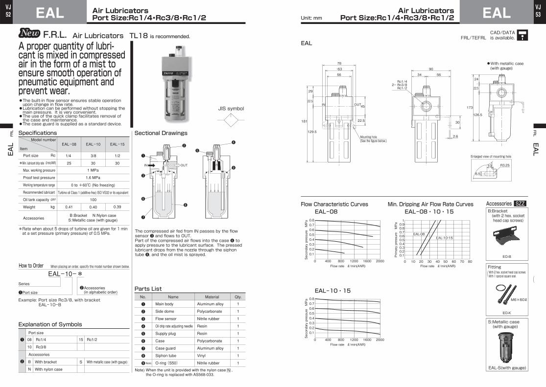
52VJ
53VJAir Lubricators
Port Size:Rc1/4・Rc3/8・Rc1/2EAL Air LubricatorsPort Size:Rc1/4・Rc3/8・Rc1/2 EAL
EAL
FRL FR
L EAL
Unit: mm
CAD/DATAis available.FRL/TEFRL
JIS symbol
EAL-10-*
Port sizeAccessories (in alphabetic order)
08
10
B
N
S
15 Rc1/2Rc1/4
Rc3/8
With bracket
With nylon case
With metallic case (with gauge)
Sectional Drawings
1/4 1/23/8
25 3030
Specifications
1
1
1
1
1
1
1
1
1
Parts List
Main body
Side dome
Flow sensor
Oil drip rate adjusting needle
Supply plug
Case
Case guard
Siphon tube
O-ring (S50)
Aluminum alloy
Polycarbonate
Nitrile rubber
Resin
Resin
Polycarbonate
Aluminum alloy
Vinyl
Nitrile rubber
Series
Example: Port size Rc3/8, with bracketEAL-10-B
EAL-08 EAL-10 EAL-15
1 MPa
1.6 MPa
100
0.40
B:Bracket N:Nylon caseS:Metallic case (with gauge)
*Rate when about 5 drops of turbine oil are given for 1 minat a set pressure (primary pressure) of 0.5 MPa.
0.390.41
Explanation of Symbols
Note)
❶
❷
❸
❹
❺
❻
❼
❽
❾
❶
❶
❷
❷
❶
❸
❻
❼
❷
❽
❺
❹
❾IN OUT
Air Lubricators TL18 is recommended.F.R.L.
●The built-in flow sensor ensures stable operation upon change in flow rate.●Lubrication can be performed without stopping the main pressure. It is very convenient.●The use of the quick clamp facilitates removal of the case and maintenance.●The case guard is supplied as a standard device.
A proper quantity of lubri-cant is mixed in compressed air in the form of a mist to ensure smooth operation of pneumatic equipment and prevent wear.
Model number
Item
Rc
ℓ/min(ANR)
kg
*
Port size
Min. lubricant drip rate
Max. working pressure
Proof test pressure
Working temperature range
Recommended lubricant
Oil tank capacity
Weight
Accessories
cm3
0 to +60℃ (No freezing)
Turbine oil Class 1 (additive-free) ISO VG32 or its equivalent
Port size
Accessories
The compressed air fed from IN passes by the flow sensor ❸ and flows to OUT.Part of the compressed air flows into the case ❻ to apply pressure to the lubricant surface. The pressed lubricant drops from the nozzle through the siphon tube ❽, and the oil mist is sprayed.
No. Name Material Qty.
How to Order When placing an order, specify the model number shown below.
Note) When the unit is provided with the nylon case ,the O-ring is replaced with AS568-033.
N
126.5
24
22.5
173
29
22.5
181
129.5
22.5
45OUTIN
30
2.6
6.5
10 R3.25
56
□63
5634
90
78
Rc1/42ー Rc3/8 Rc1/2
Enlarged view of mounting hole
Flow Characteristic CurvesEAL-08 EAL-08・10・15
EAL-10・15
Min. Dripping Air Flow Rate Curves Accessories SZZB:Bracket(with 2 hex. sockethead cap screws)
Fitting
S:Metallic case (with gauge)
EAL-S(with gauge)
With 2 hex. socket head cap screwsWith 1 special square seal
EO-B
EO-K
( (
0
0.10.20.30.40.50.60.70.8
400 800 1200 1600 2000
Secondary pressure MPa
Secondary pressure MPa
Primary pressure MPa
0 10 20 30 40 50 60 70 80
0.10.20.30.40.50.60.70.80.91
EAL-08EAL-10・15
0
0.10.20.30.40.50.60.70.8
400 800 1200 1600 2000
M6×60ℓ
EAL
Mounting hole(See the figure below.)
●With metallic case(with gauge)
Flow rate ℓ/min(ANR) Flow rate ℓ/min(ANR)
Flow rate ℓ/min(ANR)

54VJ
55VJAir Lubricators
Port Size:Rc1/2・Rc3/4MAL Air LubricatorsPort Size:Rc1/2・Rc3/4 MAL
MAL
FRL FR
L MAL
Unit: mm
CAD/DATAis available.FRL/TMFRL
JIS symbol
MAL-15-*
Port size
15
B
M
S
N
20 Rc3/4Rc1/2
With bracket
With metallic case (without gauge)
With metallic case (with gauge)
With nylon case
Sectional Drawings
25 30
Specifications
1
1
1
1
1
1
1
1
1
1
1
1
Parts List
Main body
Side dome
Flow sensor
Check ball A
Oil drip rate adjusting needle
Nozzle
Supply plug
Check ball B
Case
Case guard
Siphon tube
O-ring (G55)
Aluminum alloy
Polycarbonate
Nitrile rubber (fabric-filled)
Steel ball
Brass
Brass
Resin
Steel ball
Polycarbonate
Aluminum alloy
Vinyl
Nitrile rubber
SeriesAccessories (in alphabetic order)
Example: Port size Rc1/2, with bracket, with metallic case (without gauge)MAL-15-BM
MAL-15 MAL-20
1 MPa
1.6 MPa
130
B:Bracket M:Metallic case (without gauge)N:Nylon case S:Metallic case (with gauge)
*Rate when about 5 drops of turbine oil are given for 1min at a set pressure (primary pressure) of 0.5 MPa.
0.630.66
Explanation of Symbols
❶
❶
❶❷❸❹❺❻❼❽❾101112
10
❷ ❼
❻ ❺
❽
Lubricant
❷
❷
❾
11
12
❹
❶
❸
Air Lubricators TL28 is recommended.F.R.L.
●The built-in flow sensor ensures stable operation upon change in flow rate.●Lubrication can be performed by removing the supply plug without stopping the main pressure.●The use of the quick clamp facilitates removal of the case and maintenance.●The case guard is supplied as a standard device.
A proper quantity of lubri-cant is mixed in compressed air in the form of a mist to ensure smooth operation of pneumatic equipment and prevent wear.
Model number
Item
Rc
ℓ/min(ANR)
kg
*
Port size
Min. lubricant drip rate
Max. working pressure
Proof test pressure
Working temperature range
Recommended lubricant
Oil tank capacity
Weight
Accessories
cm3
0 to +60℃ (No freezing)
Turbine oil Class 1 (additive-free) ISO VG32 or its equivalent
Port size
Accessories
The compressed air fed from IN passes by the flow sensor ❸ and flows to OUT.Part of the compressed air depresses the check ball A ❹ and flows into the case ❾ to apply pressure to the lubricant surface. The pressed lubricant drops from the nozzle ❻ through the siphon tube 11, and the oil mist is sprayed.
No. Name Material Qty.
1/2 3/4
How to Order When placing an order, specify the model number shown below.
4
R3.5
7
56.5
138
194.5
IN OUT
55 2.6
Gauge
55
22
88.5
30
39.5
141.9
56.5
198.4
72 38.5 59.5
98
Rc1/2Rc3/42ー
Enlarged view of mounting hole
Flow Characteristic CurvesMAL-15
MAL-20
Min. Dripping Air Flow Rate Curves Accessories SZZB:Bracket (with 4 hex. sockethead cap screws)
Fitting
M:Metallic case (without gauge)S:Metallic case (with gauge)
MAL-M(without gauge)MAL-S(with gauge)
With 2 hex. socket head cap screwsWith 1 special square seal
MM-B
MM-K
( (
0.1
0 1000 2000 3000 4000 5000
0.2
0.3
0.4
0.5
0.6
0.7
0.8
Secondary pressure MPa
Secondary pressure MPa
Primary pressure MPa
Flow rate ℓ/min(ANR) Flow rate ℓ/min(ANR)
Flow rate ℓ/min(ANR)
0
0.2
0.4
0.6
0.8
1
10 20 30 40 50
MAL-15
MAL-20
0.1
0 1000 2000 3000 4000 5000
0.2
0.3
0.4
0.5
0.6
0.7
0.8 M6×70ℓ
Mounting hole(See the figure below.)
●With metallic case(without gauge/with gauge)
MAL
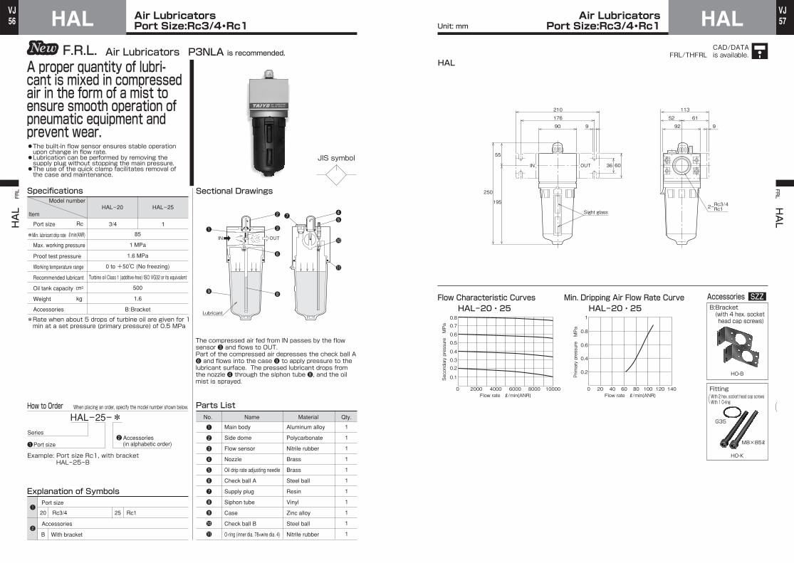
56VJ
57VJAir Lubricators
Port Size:Rc3/4・Rc1HAL Air LubricatorsPort Size:Rc3/4・Rc1 HAL
HAL
FRL FR
L HAL
Unit: mm
CAD/DATAis available.FRL/THFRL
HAL-25-*
Port size
Accessories
20
B
25 Rc1Rc3/4
With bracket
Sectional Drawings
3/4 1
Specifications
1
1
1
1
1
1
1
1
1
1
1
Parts List
Example: Port size Rc1, with bracketHAL-25-B
IN OUT
Lubricant
HAL-20 HAL-25
85
1 MPa
1.6 MPa
500
1.6
B:Bracket
*Rate when about 5 drops of turbine oil are given for 1min at a set pressure (primary pressure) of 0.5 MPa
Explanation of Symbols
JIS symbol
❶
❷
❸
❹
❺
❻
❼
❽
❾
10
11
❶
❶
❷
❷
❹❺
10
11
❼❷
❸
❻
❽
❶
❾
Air Lubricators P3NLA is recommended.F.R.L.
●The built-in flow sensor ensures stable operation upon change in flow rate.●Lubrication can be performed by removing the supply plug without stopping the main pressure.●The use of the quick clamp facilitates removal of the case and maintenance.
A proper quantity of lubri-cant is mixed in compressed air in the form of a mist to ensure smooth operation of pneumatic equipment and prevent wear.
Model number
Item
Rc
ℓ/min(ANR)
kg
*
Port size
Min. lubricant drip rate
Max. working pressure
Proof test pressure
Working temperature range
Recommended lubricant
Oil tank capacity
Weight
Accessories
cm3
0 to +50℃ (No freezing)
Turbine oil Class 1 (additive-free) ISO VG32 or its equivalent
Port sizeAccessories (in alphabetic order)
Series
The compressed air fed from IN passes by the flow sensor ❸ and flows to OUT.Part of the compressed air depresses the check ball A ❻ and flows into the case ❾ to apply pressure to the lubricant surface. The pressed lubricant drops from the nozzle ❹ through the siphon tube ❽, and the oil mist is sprayed.
No. Name Material Qty.
Main body
Side dome
Flow sensor
Nozzle
Oil drip rate adjusting needle
Check ball A
Supply plug
Siphon tube
Case
Check ball B
O-ring (inner dia. 78×wire dia. 4)
Aluminum alloy
Polycarbonate
Nitrile rubber
Brass
Brass
Steel ball
Resin
Vinyl
Zinc alloy
Steel ball
Nitrile rubber
How to Order When placing an order, specify the model number shown below.
90 9
176
210
92 9
52 61
113
195
55
IN OUT
Sight glass
250
36 60
Rc3/4Rc12ー
Flow Characteristic CurvesHAL-20・25 HAL-20・25
Min. Dripping Air Flow Rate Curve Accessories SZZB:Bracket (with 4 hex. sockethead cap screws)
FittingWith 2 hex. socket head cap screwsWith 1 O-ring
HO-B
HO-K
( (
0.1
0 2000 4000 6000 8000 10000
0.20.3
0.4
0.5
0.6
0.7
0.8
Secondary pressure MPa
Primary pressure MPa
0
0.2
0.4
0.6
0.8
1
20 40 60 80 100 120 140
M8×85ℓ
G35
HAL
Flow rate ℓ/min(ANR)Flow rate ℓ/min(ANR)

58VJ
59VJAuto Drain Traps
Port Size:Rc1/4・Rc3/8・Rc1/2EDS Auto Drain TrapsPort Size:Rc1/4・Rc3/8・Rc1/2 EDS
EDS FRL FR
L EDS
Unit: mm
CAD/DATAis available.FRL/TEFRL
JIS symbol
EDS-10-*
Port size
Accessories
08
10
B
N
15 Rc1/2Rc1/4
Rc3/8
With bracket
With nylon case
With metallic case (with gauge)S
Sectional Drawing
1/4 1/23/8Rc
kg
Specifications
1111111111111
Parts List
Example: Port size Rc3/8, with bracketEDS-10-B
Port size
Max. working pressure
Proof test pressure
Working temperature range
Draining method
Weight
Accessories
EDS-08 EDS-10 EDS-15
1 MPa
1.6 MPa
Float type automatic drain
0.41
B:Bracket N:Nylon case S:Metallic case (with gauge)
Note) The min. working pressure is 0.15 MPa.
0.400.42
Explanation of Symbols
Note)
IN
Drain
0 to +60℃ (No freezing)
Port sizeAccessories (in alphabetic order)
Series
No. Name Material Qty.
1. As drain (water) accumulates in the case ❸, the float ❻ starts floating.
2. The float ❻ rises and pushes up the pin ❾ to open the poppet ❽.3. When the poppet ❽ opens, compressed air flows onto the piston ❼ to depress the piston ❼.
4. When the piston ❼ lowers, the O-ring 10 comes off, and drain (water) is immediately discharged.
5. After the drain (water) is discharged, the float ❻ returns to the original position, and the poppet ❽ closes.
6. When the poppet ❽ closes, the compressed air above the piston ❼ is discharged to atmosphere through the orifice in the center of the piston, and the piston ❼ returns to the original position.
❶❷❸❹❺❻❼❽❾10111213
❶
❶
❷
❷
❺
12
❾
❽
❼
11
13
❶
❸
❻
10
❷
❹
●The use of the quick clamp facilitates removal of the case and maintenance.●The case guard is supplied as a standard device.
Device to automatically discharge drain.
Model number
Item
Main bodyFilter elementCaseCase guardResidual pressure discharging plugFloatPistonPoppetPinO-ringFilter netO-ring(S50)O-ring(S16)
Aluminum alloyPolypropylenePolycarbonateAluminum alloyCarbon steel for machine structural use
- - - -- -
Nitrile rubberNitrile rubber
How to Order When placing an order, specify the model number shown below.
Note) When the unit is provided with the nylon case ,the O-ring is replaced with AS568-033.
N
22.5
18
170129.5
56
□63
78
22.5
45IN
5634
90Residual pressure discharging plug
30
2.6
6.5
126.5
Gauge
22
22.5
169
10 R3.25
Accessories SZZB:Bracket(with 2 hex. sockethead cap screws)
S:Metallic case
EO-B
・With gauge EAF-AS(with automatic drain valve)
Enlarged view of mounting hole
EDS
Mounting hole(See the figure below.)
●With metallic case(with gauge)

60VJ
61VJAuto Drain Traps
Port Size:Rc1/2・Rc3/4MDS Auto Drain TrapsPort Size:Rc1/2・Rc3/4 MDS
MDS FRL FR
L MDS
Unit: mm
CAD/DATAis available.FRL/TMFRL
JIS symbol
MDS-15-*
15
B
M
20 Rc3/4Rc1/2
With bracket
With metallic case (without gauge)
With metallic case (with gauge)
With nylon case
S
N
Sectional Drawing
Rc
Specifications
1111111111111
Parts List
Example: Port size Rc1/2, with bracket, with metalliccase (without gauge) MDS-15-BM
Port size
Max. working pressure
Proof test pressure
Working temperature range
Draining method
Weight
Accessories
MDS-15 MDS-20
1 MPa
1.6 MPa
Float type automatic drain
B:Bracket N:Nylon caseM:Metallic case (without gauge) S:Metallic case (with gauge)
Note) The min. working pressure is 0.15 MPa.
0.680.71
Explanation of Symbols
kg
IN
Drain
❶
❶
❷
❷
❶❷❸❹❺❻❼❽❾10111213
❺
12
❷
❾
❽❼
1113
❶
❸
❹
❻
10
●The use of the quick clamp facilitates removal of the case and maintenance.●The case guard is supplied as a standard device.
Device to automatically discharge drain.
Model number
Item
0 to +60℃ (No freezing)
Port sizeAccessories (in alphabetic order)
Series
Port size
Accessories
1. As drain (water) accumulates in the case ❸, the float ❻ starts floating.
2. The float ❻ rises and pushes up the pin ❾ to open the poppet ❽.
3. When the poppet ❽ opens, compressed air flows onto the piston ❼ to depress the piston ❼.
4. When the piston ❼ lowers, the O-ring 10 comes off, and drain (water) is immediately discharged.
5. After the drain (water) is discharged, the float ❻ returns to the original position, and the poppet ❽ closes.
6. When the poppet ❽ closes, the compressed air above the piston ❼ is discharged to atmosphere through the orifice in the center of the piston, and the piston ❼ returns to the original position.
No. Name Material Qty.Main bodyFilter elementCaseCase guardResidual pressure discharging plugFloatPistonPoppetPinO-ringFilter netO-ring(G55)O-ring(S16)
Aluminum alloyPolypropylenePolycarbonateAluminum alloyCarbon steel for machine structural use
- - - -- -
Nitrile rubberNitrile rubber
1/2 3/4
How to Order When placing an order, specify the model number shown below.
4
R3.5
7
Gauge
39.5
163.8
27.5
191.3
2.6
30
38.5 59.5
98□72
Mounting hole(See the figure below.)
Residual pressuredischarging plug
55
22
20
134
IN27.5
181.555
Enlarged view of mounting hole
Accessories SZZB:Bracket (with 4 hex. sockethead cap screws)
MM-B
MDS
●With metallic case(without gauge/with gauge)
M:Metallic case (without gauge)S:Metallic case (with gauge)
MAF-AM(without gauge)MAF-AS(with gauge)

62VJ
63VJMicro-fi lters
Port Size:Rc1/8・Rc1/4SFF Micro-fi ltersPort Size:Rc1/8・Rc1/4 SFF
SFF FRL FR
L SFF
Unit: mm
JIS symbol
SFF-08-*
06
None
B
G
08 Rc1/4Rc1/8
N
M
Sectional Drawing
1/8 1/4Rc
kg
Specifications
111111111
Parts List
Example: Port size Rc1/4, with bracketSFF-08-B
Port size
Max. working pressure
Proof test pressure
Working temperature range
Solid and oil removal rate
Weight
Accessories
SFF-06 SFF-08
1 MPa
1.6 MPa
+5 to +60℃
99.999% or more
0.22
B:Bracket G:Case guardN:Nylon case M:Metallic case (without gauge)
Explanation of Symbols
IN
Drain
OUT
❶
❶
❷
❷
❶❷❸❹❺❻❼❽❾
❽
❻
❹
❼
❶
❾
❷
❸
❺
Coalescing Filters TM08 is recommended.F.R.L.
●Suitable for removing oil mist.●The rate of removal of particles of 0.01 μm or more is 99.999% or more.
Fine particles, oil and mois-ture which cannot be removed by general filters can be removed.
Model number
Item
Port sizeAccessories (in alphabetic order)
Series
Port size
Accessories
With manual drain valve
With bracket
With case guard
With nylon case
With metallic case (without gauge)
Particles (dust, moisture and oil) with a size of 0.01 μm or more in the contaminated compressed air fed from IN are trapped and coagulated by this filter element at a rate of 99.999%. Solid contaminants are left in the filter element, and liquid moisture and oil are coagulated in the pleated filter paper due to their own diffusion and adhesion and pushed out of the filter. A urethane foam part is provided to prevent the pushed out liquid from scattering to the secondary side. The pushed out liquid collects under the element and drops onto the bottom of the case.
No. Name Material Qty.Main bodyFilter element assemblyCaseDrain valveSeat sealDrain valve springTubeO-ring(AS568-024)O-ring(P11.2)
Zinc alloy-
PolycarbonateResinNitrile rubberSpring steelVinylNitrile rubberNitrile rubber
How to Order When placing an order, specify the model number shown below.
82
30
15IN OUT
127
30
7
8
2ーRc1/8 Rc1/4
13
304ーM4depth 5
30
15
31
83.5129.5
4.51.5
R2.25
19 25
44
2
Vinyl hose for drain
Vinyl hose for drain
27
□38
Enlarged view of mounting hole
●With metallic case(without gauge)
Flow Characteristic CurvesSFF-06・08
Accessories SZZB:Bracket (with 2 mountingscrews)
Fitting
M:Metallic case(without gauge)
・Without gauge SAF-M(with manual drain valve)
SO-B
SO-K
With 2 connecting screwsWith 1 O-ring( (
Recommended application example
Compressed air Standard filter
Standard filter
(5-μm filter element)
(5-μm filter element)
Micro-filter Clean air free from oil,moisture and solid particles
Clean air free from oil, moisture,solid particles and bacteria
Use●Food processors●Packaging machines●Spray coaters●Chemical industry
●Dairy industry and brewing industry●Air micrometers●Fluidics●Other precision instruments
0.1
0 200 400 600 800 1000
0.2
0.3
0.4
0.5
0.6
0.7
0.8
Secondary pressure MPa
S15
M4×45ℓ
SFF
Mounting hole(See the figure below.)
Flow rate ℓ/min(ANR)
Recommended max. flow rate
Micro-filter Micro-filter

64VJ
65VJMicro-fi lters
Port Size:Rc1/4・Rc3/8・Rc1/2EFF Micro-fi ltersPort Size:Rc1/4・Rc3/8・Rc1/2 EFF
EFF
FRL FR
L EFF
Unit: mm
JIS symbol
EFF-08-*
08
10
None
A
B
15 Rc1/2Rc1/4
Rc3/8
With manual drain valve
With automatic drain valve
With bracket
With nylon case
With metallic case (with gauge)
N
S
Sectional Drawing
1/4 1/23/8Rc
Specifications
1111111111
Parts List
Example: Port size Rc1/4, with automatic drain valve,with bracket EFF-08-AB
Accessories
Port size
Max. working pressure
Proof test pressure
Working temperature range
Solid and oil removal rate
Draining method
kgWeight
EFF-08 EFF-10 EFF-15
0.44
0.46
0.43
0.45
0.42
0.44
1 MPa
1.6 MPa
99.999% or more
Standard: Quick manual draining Semi-standard: Float type automatic drain
A:Automatic drain valve B:Bracket N:Nylon case S:Metallic case (with gauge)
Note) The min. working pressure of the unit with anautomatic drain valve is 0.15 MPa.
Explanation of Symbols
Note)
❶❷
❶
❷
❶
❾
❷
❸
❹
❺
10
❼
❻
❽
Model number
Item
0 to +60℃ (No freezing)
Port sizeAccessories (in alphabetic order)
Series
Port size
Accessories
No. Name Material Qty.
Automaticdraining
Manualdraining
Particles (dust, moisture and oil) with a size of 0.01 μm or more in the contaminated compressed air fed from IN are trapped and coagulated by this filter element at a rate of 99.999%. Solid contaminants are left in the filter element, and liquid moisture and oil are coagulated in the pleated filter paper due to the diffusion and adhesion of the particles and pushed out of the filter. A urethane foam part is provided to prevent the pushed out liquid from scattering to the secondary side. The pushed out liquid collects under the element and drops onto the bottom of the case.
Drain
IN OUT
Main bodyFilter element assemblyCaseCase guardDrain valveO-ring(S16)Drain valve springTubeO-ring(S50)O-ring(P20)
Aluminum alloy-
PolycarbonateAluminum alloyResinNitrile rubberSpring steelVinylNitrile rubberNitrile rubber
❶❷❸❹❺❻❼❽❾10
Coalescing Filters TM18 is recommended.F.R.L.
●Suitable for removing oil mist.●The rate of removal of particles of 0.01 μm or more is 99.999% or more.●The use of the quick clamp facilitates removal of the case and maintenance.●The case guard is supplied as a standard device.
Fine particles, oil and mois-ture which cannot be removed by general filters can be removed.
Manual draining
Automatic draining
How to Order When placing an order, specify the model number shown below.
Note) When the unit is provided with the nylon case ,the O-ring is replaced with AS568-033.
N
126.5
22.5
182(169)
178.5(170)
33(20)
26.5(18)
22.5
129.5
22.5
45OUTIN
30
2.6
6.5
10 R3.25
56
□63
5634
90
78
Rc1/42ー Rc3/8 Rc1/2
Vinyl hose for drain
Vinyl hose for drainEnlarged view of mounting hole
The parenthesized values are the dimensionsof the unit with an automatic drain valve.
With automaticdrain valve
Fit a tube with an innerdiameter of 8 mm to this part.( (
●With metallic case(with gauge)
Gauge
Flow Characteristic CurvesEFF-08 EFF-10・15
Recommended application example
0
0.10.20.30.40.50.60.70.8
200 400 600 800 1000
Secondary pressure MPa
Secondary pressure MPa
0
0.10.20.30.40.50.60.70.8
200 400 600 800 1000
Accessories SZZA:Automatic drain valve B:Bracket
(with 2 hex. sockethead cap screws)
EAF-A EO-B
Fitting
EO-K
With 2 hex. socket head cap screwsWith 1 special square seal( (
S:Metallic case (with gauge)
・With gaugeEAF-S(with manual drain valve)EAF-AS(with manual drain valve)
M6×60ℓ
EFF
Mounting hole(See the figure below.)
Flow rate ℓ/min(ANR) Flow rate ℓ/min(ANR)
Recommended max. flow rate
Recommended max. flow rate
Compressed air Standard filter
Standard filter
(5-μm filter element)
(5-μm filter element)
Micro-filter Clean air free from oil,moisture and solid particles
Clean air free from oil, moisture,solid particles and bacteriaMicro-filter Micro-filter
Use●Food processors●Packaging machines●Spray coaters●Chemical industry
●Dairy industry and brewing industry●Air micrometers●Fluidics●Other precision instruments
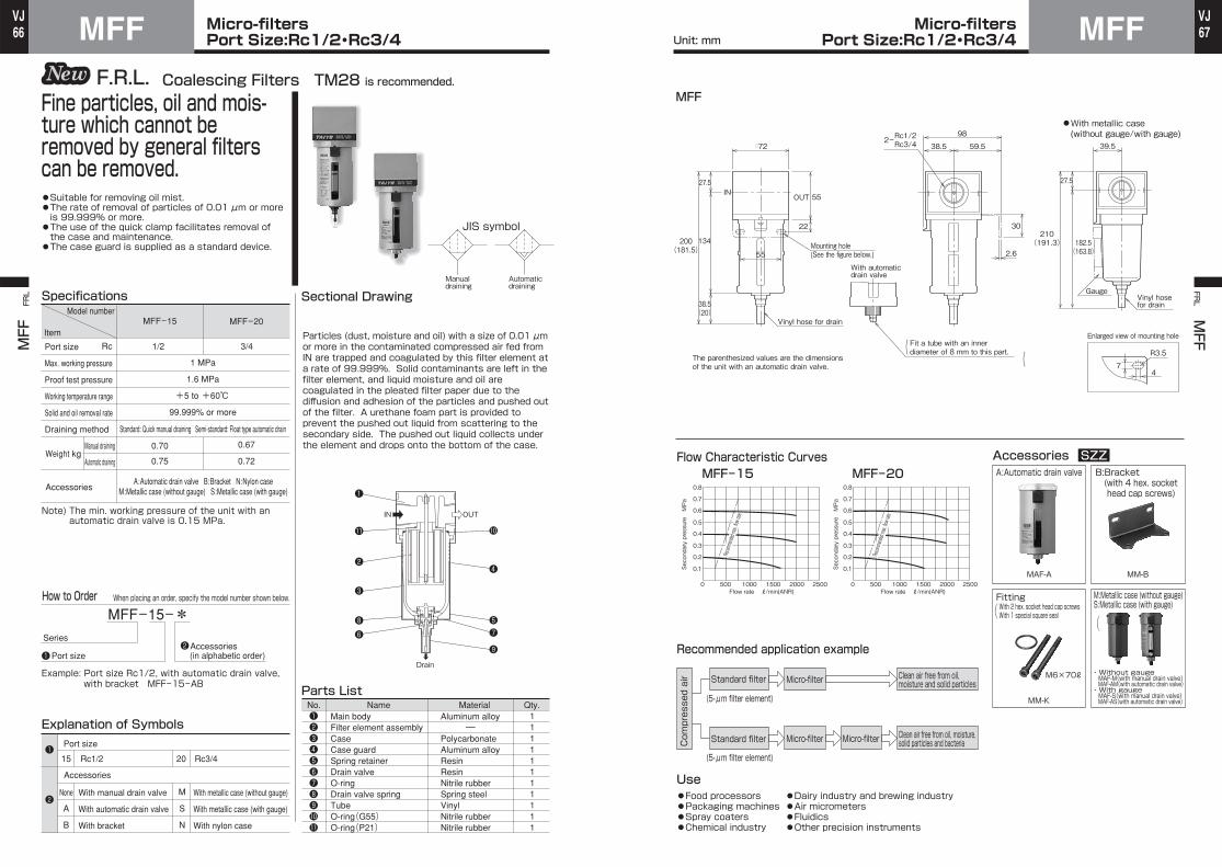
66VJ
67VJMicro-fi lters
Port Size:Rc1/2・Rc3/4MFF Micro-fi ltersPort Size:Rc1/2・Rc3/4 MFF
MFF FRL FR
L MFF
Unit: mm
MFF-15-*
15
A
B
20 Rc3/4Rc1/2
M
S
N
Specifications
11111111111
Parts ListNo. Name Material Qty.
Example: Port size Rc1/2, with automatic drain valve,with bracket MFF-15-AB
MFF-15
0.70
0.75
MFF-20
0.67
0.72
1 MPa
1.6 MPa
+5 to +60℃
99.999% or more
A:Automatic drain valve B:Bracket N:Nylon caseM:Metallic case (without gauge) S:Metallic case (with gauge)
Note) The min. working pressure of the unit with anautomatic drain valve is 0.15 MPa.
Explanation of Symbols❶❷❸❹❺❻❼❽❾1011
❶❷
❶
❷
❶
11
❷
❸
❽❻
10
❹
❺❼
❾Drain
IN OUT
Coalescing Filters TM28 is recommended.F.R.L.
●Suitable for removing oil mist.●The rate of removal of particles of 0.01 μm or more is 99.999% or more.●The use of the quick clamp facilitates removal of the case and maintenance.●The case guard is supplied as a standard device.
Fine particles, oil and mois-ture which cannot be removed by general filters can be removed.
Rc
Accessories
Port size
Max. working pressure
Proof test pressure
Working temperature range
Solid and oil removal rate
Draining method
kgWeight
Model number
Item
Manual draining
Automatic draining
1/2 3/4
Standard: Quick manual draining Semi-standard: Float type automatic drain
Port sizeAccessories (in alphabetic order)
Series
None
Port size
Accessories
With manual drain valve
With automatic drain valve
With bracket
With metallic case (without gauge)
With metallic case (with gauge)
With nylon case
JIS symbol
Automaticdraining
Manualdraining
Sectional Drawing
Particles (dust, moisture and oil) with a size of 0.01 μm or more in the contaminated compressed air fed from IN are trapped and coagulated by this filter element at a rate of 99.999%. Solid contaminants are left in the filter element, and liquid moisture and oil are coagulated in the pleated filter paper due to the diffusion and adhesion of the particles and pushed out of the filter. A urethane foam part is provided to prevent the pushed out liquid from scattering to the secondary side. The pushed out liquid collects under the element and drops onto the bottom of the case.
Main bodyFilter element assemblyCaseCase guardSpring retainerDrain valveO-ringDrain valve springTubeO-ring(G55)O-ring(P21)
Aluminum alloy-
PolycarbonateAluminum alloyResinResinNitrile rubberSpring steelVinylNitrile rubberNitrile rubber
How to Order When placing an order, specify the model number shown below.
4
R3.5
7
27.5
134
INOUT
2.6
55
22
Mounting hole(See the figure below.)
30
39.5
27.5
□72 38.5 59.5
982ーRc1/2 Rc3/4
55
200(181.5)
210(191.3) 182.5
(163.8)
38.5(20)
Vinyl hose for drain
Gauge
Vinyl hose for drain
Enlarged view of mounting hole
With automaticdrain valve
The parenthesized values are the dimensionsof the unit with an automatic drain valve.
Fit a tube with an innerdiameter of 8 mm to this part.( (
●With metallic case(without gauge/with gauge)
Flow Characteristic CurvesMFF-15 MFF-20
Recommended application example
Accessories SZZ
MAF-A MM-B
MM-K
M:Metallic case (without gauge)S:Metallic case (with gauge)
・Without gauge MAF-M(with manual drain valve) MAF-AM(with automatic drain valve)・With gauge MAF-S(with manual drain valve) MAF-AS(with automatic drain valve)
0.1
0 500 1000 1500 2000 2500
0.2
0.3
0.4
0.5
0.6
0.7
0.8
Secondary pressure MPa
Secondary pressure MPa
Flow rate ℓ/min(ANR) Flow rate ℓ/min(ANR)
0.1
0 500 1000 1500 2000 2500
0.2
0.3
0.4
0.5
0.6
0.7
0.8
M6×70ℓ
MFF
Compressed air Standard filter
Standard filter
(5-μm filter element)
(5-μm filter element)
Micro-filter Clean air free from oil,moisture and solid particles
Clean air free from oil, moisture,solid particles and bacteriaMicro-filter Micro-filter
Use●Food processors●Packaging machines●Spray coaters●Chemical industry
●Dairy industry and brewing industry●Air micrometers●Fluidics●Other precision instruments
A:Automatic drain valve B:Bracket (with 4 hex. sockethead cap screws)
FittingWith 2 hex. socket head cap screwsWith 1 special square seal( (
Recommended max. flow rate
Recommended max. flow rate

68VJ
69VJMicro-fi lters
Port Size:Rc3/4・Rc1HFF Micro-fi ltersPort Size:Rc3/4・Rc1 HFF
HFF FRL FR
L HFF
Unit: mm
HFF-25-*
20
None
A
25 Rc1Rc3/4
With manual drain valve
With automatic drain valve
With bracketB
Sectional Drawing
Particles (dust, moisture and oil) with a size of 0.01 μm or more in the contaminated compressed air fed from IN are trapped and coagulated by this filter element at a rate of 99.999%. Solid contaminants are left in the filter element, and liquid moisture and oil are coagulated in the pleated filter paper due to the diffusion and adhesion of the particles and pushed out of the filter. A urethane foam part is provided to prevent the pushed out liquid from scattering to the secondary side. The pushed out liquid collects under the element and drops onto the bottom of the case.
1
Specifications
1111111111
Parts ListExample: Port size Rc1, with automatic drain valve,
with bracket HFF-25-AB
Drain
IN OUT
HFF-20
2.2
2.3
HFF-25
2.2
2.3
1 MPa
1.6 MPa
+5 to +50℃
99.999% or more
Standard: Quick manual draining Semi-standard: Float type automatic drain
Explanation of Symbols❶❷❸❹❺❻❼❽❾10
❶❷
❶
❷
❸
❹❻
❽
❶
10
❷
❾
❼❺
Coalescing Filters P3NFA is recommended.F.R.L.
●Suitable for removing oil mist.●The rate of removal of particles of 0.01 μm or more is 99.999% or more.●The use of the quick clamp facilitates removal of the case and maintenance.
Fine particles, oil and mois-ture which cannot be removed by general filters can be removed.
JIS symbol
Automaticdraining
Manualdraining
Rc
Accessories
Port size
Max. working pressure
Proof test pressure
Working temperature range
Solid and oil removal rate
Draining method
kgWeight
Model number
Item
Manual draining
Automatic draining
3/4
A:Automatic drain valve B:Bracket
Port sizeAccessories (in alphabetic order)
Series
Port size
Accessories
No. Name Material Qty.Main bodyFilter element assemblyCaseSpring retainerDrain valveO-ring(S16)Drain valve springTubeO-ring (inner dia. 78×wire dia. 4)O-ring(S32)
Aluminum alloy-
Zinc alloyResinResinNitrile rubberSpring steelVinylNitrile rubberNitrile rubber
How to Order When placing an order, specify the model number shown below.
323(305) 293
(275)
Vinyl hose for drain
Sight glass
90
9
176
210
92 6
52 61
113
30IN OUT 36 60
With automatic drain valve
The parenthesized values are the dimensionsof the unit with an automatic drain valve.
Fit a tube with an innerdiameter of 8 mm to this part.( (
Flow Characteristic CurvesHFF-20・25
Accessories SZZA:Automatic drain valve
B:Bracket (with 4 hex. sockethead cap screws)
HO-B
HAF-A
HO-K
Recommended application example
0
0.1
0.20.3
0.40.5
0.60.70.8
0.9
1000 2000 3000 4000 5000 6000
Secondary pressure MPa
Flow rate ℓ/min(ANR)
Recommended max. flow rate
G35
M8×85ℓ
HFF
Compressed air Standard filter
Standard filter
(5-μm filter element)
(5-μm filter element)
Micro-filter Clean air free from oil,moisture and solid particles
Clean air free from oil, moisture,solid particles and bacteria
Use●Food processors●Packaging machines●Spray coaters●Chemical industry
●Dairy industry and brewing industry●Air micrometers●Fluidics●Other precision instruments
Micro-filter Micro-filter
FittingWith 2 hex. socket head cap screwsWith 1 O-ring( (
Rc3/4Rc1
2ー

70VJ
71VJ
SMF SMFMist SeparatorsPort Size:Rc1/8・Rc1/4
Mist SeparatorsPort Size:Rc1/8・Rc1/4
SMF
FRL FR
L SMF
Unit: mm
JIS symbol
SMF-08-*
06
None
B
G
08 Rc1/4Rc1/8
With manual drain valve
With bracket
With case guard
With nylon case
With metallic case (without gauge)
N
M
Sectional Drawing
Rc
Specifications
111111111
Parts List
Example: Port size Rc1/4, with bracketSMF-08-B
SMF-06 SMF-08
1 MPa
1.6 MPa
+5 to +60℃
99% or more
0.22
Explanation of Symbols❶❷❸❹❺❻❼❽❾
❶❷
❶
❷
❶
❾
❷
❸
❺
❽
❻
❹
❼
Accessories
Port size
Max. working pressure
Proof test pressure
Working temperature range
Solid and oil removal rate
kgWeight
Model number
Item
1/41/8
Port sizeAccessories (in alphabetic order)
Series
Port size
Accessories
Particles (dust, moisture and oil) with a size of 0.3 μm or more in the contaminated compressed air fed from IN are trapped and coagulated by this filter element at a rate of 99%. Solid contaminants are left in the filter element, and liquid moisture and oil are coagulated in the element due to the diffusion and adhesion of the particles and pushed out of the filter. A urethane foam part is provided to prevent the pushed out liquid from scattering to the secondary side. The pushed out liquid collects under the element and drops onto the bottom of the case.
No. Name Material Qty.Main bodyFilter element assemblyCaseDrain valveSeat sealDrain valve springTubeO-ring(AS568-024)O-ring(P11.2)
Zinc alloy-
PolycarbonateResinNitrile rubberSpring steelVinylNitrile rubberNitrile rubber
B:Bracket G:Case guardN:Nylon case M:Metallic case (without gauge)
How to Order When placing an order, specify the model number shown below.
IN
Drain
OUT
Coalescing Filters TM08 is recommended.F.R.L.
●Suitable for removing oil mist.●The rate of removal of particles of 0.3 μm or more is 99% or more.
Fine particles, oil and mois-ture which cannot be removed by general filters can be removed.
82
30
15IN OUT
127
30
7
8
Mounting hole(See the figure below.)
2ーRc1/8 Rc1/4
13
304ーM4depth 5
30
15
31
83.5129.5
4.51.5
R2.25
19 25
44
2
Vinyl hose for drain
Vinyl hose for drain
27
□38
Enlarged view of mounting hole
●With metallic case(without gauge)
Flow Characteristic CurvesSMF-06・08
Accessories SZZB:Bracket(with 2 mounting screws)
SO-B0.1
0 100 200 300 400 500
0.2
0.3
0.4
0.5
0.6
0.7
0.8
Secondary pressure MPa
Flow rate ℓ/min(ANR)
M:Metallic case (without gauge)
・Without gaugeSAF-M(with manual drain valve)
SO-K
S15
M4×45ℓ
SMF
Recommended max. flow rate
Use●Packaging machines●Spray coaters●Chemical industry●Dairy industry andbrewing industry
●Air micrometers●Fluidics●Other precision instruments
FittingWith 2 connecting screwsWith 1 O-ring( (

72VJ
73VJ
EMF
FRL
Mist SeparatorsPort Size:Rc1/4・Rc3/8・Rc1/2EMF Mist Separators
Port Size:Rc1/4・Rc3/8・Rc1/2 EMFFRL EMF
Unit: mm
CAD/DATAis available.FRL/TEFRL
EMF-08-*
08
10
None
A
B
15 Rc1/2Rc1/4
Rc3/8
With manual drain valve
With automatic drain valve
With bracket
With nylon case
With metallic case (with gauge)
N
S
Sectional DrawingSpecifications
1
1
1
1
1
1
1
1
1
1
Parts ListExample: Port size Rc1/4, with automatic drain valve,with bracket EMF-08-AB
EMF-08 EMF-10 EMF-15
0.44
0.46
0.43
0.45
0.42
0.44
1 MPa
1.6 MPa
+5 to +60℃
99% or more
Note) The min. working pressure of the unit with anautomatic drain valve is 0.15 MPa.
Explanation of Symbols
Note)
Manualdraining
Automaticdraining
JIS symbol
❶❷
❶
❷
❶❷❸❹❺❻❼❽❾10
IN OUT
Drain
❶
❾
❷
❸
❹
❻
10
❼
❺
❽
Coalescing Filters TM18 is recommended.F.R.L.
●Suitable for removing oil mist.●The rate of removal of particles of 0.3 μm or more is 99% or more.●The use of the quick clamp facilitates removal of the case and maintenance.●The case guard is supplied as a standard device.
Fine particles, oil and mois-ture which cannot be removed by general filters can be removed.
Rc
Accessories
Port size
Max. working pressure
Proof test pressure
Working temperature range
Solid and oil removal rate
Draining method
kgWeight
Model number
Item
Manual draining
Automatic draining
1/4 1/23/8
Standard: Quick manual draining Semi-standard: Float type automatic drain
A:Automatic drain valve B:Bracket N:Nylon case S:Metallic case (with gauge)
Port sizeAccessories (in alphabetic order)
Series
Port size
Accessories
Particles (dust, moisture and oil) with a size of 0.3 μm or more in the contaminated compressed air fed from IN are trapped and coagulated by this filter element at a rate of 99%. Solid contaminants are left in the filter element, and liquid moisture and oil are coagulated in the element due to the diffusion and adhesion of the particles and pushed out of the filter. A urethane foam part is provided to prevent the pushed out liquid from scattering to the secondary side. The pushed out liquid collects under the element and drops onto the bottom of the case.
Main body
Filter element assembly
Case
Case guard
Drain valve
O-ring(S16)Drain valve spring
Tube
O-ring(S50)O-ring(P20)
Aluminum alloy
- Polycarbonate
Aluminum alloy
Resin
Nitrile rubber
Spring steel
Vinyl
Nitrile rubber
Nitrile rubber
No. Name Material Qty.
How to Order When placing an order, specify the model number shown below.
Note) When the unit is provided with the nylon case ,the O-ring is replaced with AS568-033.
N
Rc1/4Rc3/8Rc1/2
56
63
78
22.5
129.5
26.5(18)
178.5(170)
22.5
126.5
33(20)
182(169)
45
22.5
Vinyl hose for drain
Vinyl hose for drain
Gauge30
2.6
34 56
90
6.5
R3.2510
Enlarged view of mounting hole
The parenthesized values are the dimensionsof the unit with an automatic drain valve.
IN OUT
2ー
Flow Characteristic CurvesEMF-08 EMF-10・15
Accessories SZZA:Automatic drain valve B:Bracket
(with 2 hex. sockethead cap screws)
EAF-A EO-B
EO-K
S:Metallic case (with gauge)
・With gaugeEAF-S(with manual drain valve)EAF-AS(with manual drain valve)
0
0.10.20.30.40.50.60.70.8
200 400 600 800 1000
Secondary pressure MPa
Secondary pressure MPa
Flow rate ℓ/min(ANR) Flow rate ℓ/min(ANR)0
0.10.20.30.40.50.60.70.8
200 400 600 800 1000
M6×60ℓ
EMF
Mounting hole(See the figure below.)
Fit a tube with an innerdiameter of 8 mm to this part.( (
●With metallic case(with gauge)
Use●Packaging machines●Spray coaters●Chemical industry●Dairy industry andbrewing industry
●Air micrometers●Fluidics●Other precision instruments
Recommended max. flow rate
Recommended max. flow rate
FittingWith 2 hex. socket head cap screwsWith 1 special square seal( (
With automaticdrain valve

74VJ
75VJMist Separators
Port Size:Rc1/2・Rc3/4MMF Mist SeparatorsPort Size:Rc1/2・Rc3/4 MMF
MMF
FRL FR
L MMF
Unit: mm
CAD/DATAis available.FRL/TMFRL
MMF-15-*
15
None
A
B
20 Rc3/4Rc1/2
With manual drain valve
With automatic drain valve
With bracket
With metallic case (without gauge)
With metallic case (with gauge)
With nylon case
M
S
N
Sectional DrawingSpecifications
1
1
1
1
1
1
1
1
1
1
1
Parts ListNo. Name Material Qty.
Example: Port size Rc1/2, with automatic drain valve,with bracket MMF-15-AB
MMF-15
0.70
0.75
MMF-20
0.67
0.72
1 MPa
1.6 MPa
+5 to +60℃
99% or more
Standard: Quick manual draining Semi-standard: Float type automatic drain
Note) The min. working pressure of the unit with anautomatic drain valve is 0.15 MPa.
Explanation of Symbols
❶❷
❶
❷
❶
❷
❸
❹
❺
❻
❼
❽
❾
10
11
IN OUT
Drain
❶
11
❷
❸
❽❻
10
❹
❺❼
❾
Coalescing Filters TM28 is recommended.F.R.L.
●Suitable for removing oil mist.●The rate of removal of particles of 0.3 μm or more is 99% or more.●The use of the quick clamp facilitates removal of the case and maintenance.●The case guard is supplied as a standard device.
Fine particles, oil and mois-ture which cannot be removed by general filters can be removed.
Manualdraining
Automaticdraining
JIS symbol
Rc
Accessories
Port size
Max. working pressure
Proof test pressure
Working temperature range
Solid and oil removal rate
Draining method
kgWeight
Model number
Item
Manual draining
Automatic draining
1/2 3/4
A:Automatic drain valve B:Bracket N:Nylon caseM:Metallic case (without gauge) S:Metallic case (with gauge)
Port sizeAccessories (in alphabetic order)
Series
Port size
Accessories
Particles (dust, moisture and oil) with a size of 0.3 μm or more in the contaminated compressed air fed from IN are trapped and coagulated by this filter element at a rate of 99%. Solid contaminants are left in the filter element, and moisture and oil are coagulated in the element due to the diffusion and adhesion of the particles and pushed out of the filter. A urethane foam part is provided to prevent the pushed out liquid from scattering to the secondary side. The pushed out liquid collects under the element and drops onto the bottom of the case.
Main body
Filter element assembly
Case
Case guard
Spring retainer
Drain valve
O-ring(S16)
Drain valve spring
Tube
O-ring(G55)
O-ring(P21)
Aluminum alloy
-
Polycarbonate
Aluminum
Resin
Resin
Nitrile rubber
Spring steel
Vinyl
Nitrile rubber
Nitrile rubber
How to Order When placing an order, specify the model number shown below.
27.5
134
38.5(20)
200(181.5)
□72
55
22
55
Vinyl hose for drain
30
38.5 59.5
98
2.6
Vinyl hose or drain
Gauge
27.5
182.5(163.8)
210(191.3)
39.5
IN OUT
7
R3.5
4
Enlarged view of mounting hole
Rc1/2Rc3/42ー
With automaticdrain valve
Flow Characteristic CurvesMMF-15・20
Accessories SZZA:Automatic drain valve B:Bracket
(with 4 hex. sockethead cap screws)
MAF-A MM-B
・Without gaugeMAF-M(with manual drain valve)MAF-AM(with automatic drain valve)・With gaugeMAF-S(with manual drain valve)MAF-AS(with automatic drain valve)
0.1
0 200 400 600 800 1000 1200 1400 1600 1800 2000
0.2
0.3
0.4
0.5
0.6
0.7
0.8
Secondary pressure MPa
Flow rate ℓ/min(ANR)
Recommended max. flow rate
MM-K
M6×70ℓ
MMF
The parenthesized values are the dimensionsof the unit with an automatic drain valve.
Fit a tube with an innerdiameter of 8 mm to this part.( (
Mounting hole(See the figure below.)
●With metallic case(without gauge/with gauge)
Use●Packaging machines●Spray coaters●Chemical industry●Dairy industry andbrewing industry
●Air micrometers●Fluidics●Other precision instruments
FittingWith 2 hex. socket head cap screwsWith 1 special square seal( (
M:Metallic case (without gauge)S:Metallic case (with gauge)

76VJ
77VJMist Separators
Port Size:Rc3/4・Rc1HMF Mist SeparatorsPort Size:Rc3/4・Rc1 HMF
HMF
FRL FR
L HMF
Unit: mm
CAD/DATAis available.FRL/THFRL
HMF-25-*
20
None
A
25 Rc1Rc3/4
With manual drain valve
With automatic drain valve
B With bracket
Sectional Drawing
1
Specifications
1
1
1
1
1
1
1
1
1
1
Parts List
Example: Port size Rc1, with automatic drain valve, with bracket HMF-25-AB
HMF-20
2.2
2.3
HMF-25
2.2
2.3
1 MPa
1.6 MPa
99% or more
A:Automatic drain valve B:Bracket Note) The min. working pressure of the unit with an
automatic drain valve is 0.15 MPa.
Explanation of Symbols
IN OUT
Drain
❶❷
❶
❷
❶
❷
❸
❹
❺
❻
❼
❽
❾
10
❶
10
❾
❷
❼❺
❸
❹❻
❽
Coalescing Filters P3NFA is recommended.F.R.L.
●Suitable for removing oil mist.●The rate of removal of particles of 0.3 μm or more is 99% or more.●The use of the quick clamp facilitates removal of the case and maintenance.
Fine particles, oil and mois-ture which cannot be removed by general filters can be removed.
Rc
Accessories
Port size
Max. working pressure
Proof test pressure
Working temperature range
Solid and oil removal rate
Draining method
kgWeight
Model number
Item
Manual draining
Automatic draining
+5 to +50℃
Standard: Quick manual draining Semi-standard: Float type automatic drain
3/4
Port sizeAccessories (in alphabetic order)
Series
Port size
Accessories
Manualdraining
Automaticdraining
JIS symbol
Particles (dust, moisture and oil) with a size of 0.3 μm or more in the contaminated compressed air fed from IN are trapped and coagulated by this filter element at a rate of 99%. Solid contaminants are left in the filter element, and liquid moisture and oil are coagulated in the element due to the diffusion and adhesion of the particles and pushed out of the filter. A urethane foam part is provided to prevent the pushed out liquid from scattering to the secondary side. The pushed out liquid collects under the element and drops onto the bottom of the case.
No. Name Material Qty.
Main body
Filter element assembly
Case
Spring retainer
Drain valve
O-ring(S16)
Drain valve spring
Tube
O-ring (inner dia. 78×wire dia. 4)
O-ring(S32)
Aluminum alloy
-
Zinc alloy
Resin
Resin
Nitrile rubber
Spring steel
Vinyl
Nitrile rubber
Nitrile rubber
How to Order When placing an order, specify the model number shown below.
323(305) 293
(275)
Vinyl hose for drain
Sight glass
With automatic drain valve
90
9
176
210
92 6
52 61
113
30IN OUT 36 60
The parenthesized values are the dimensionsof the unit with an automatic drain valve.
Flow Characteristic CurvesHMF-20・25
Accessories SZZA:Automatic drain valve
B:Bracket (with 4 hex. sockethead cap screws)
HAF-A
HO-B
0.1
0 2000 4000 6000 8000 10000
0.2
0.3
0.4
0.5
0.6
0.7
0.8
Flow rate ℓ/min(ANR)
HO-K
G35
M8×85ℓ
HMF
Fit a tube with an innerdiameter of 8 mm to this part.( (
Use●Packaging machines●Spray coaters●Chemical industry●Dairy industry andbrewing industry
●Air micrometers●Fluidics●Other precision instruments
Secondary pressure MPa
Recommended max. flow rate
FittingWith 2 hex. socket head cap screwsWith 1 O-ring( (
Rc3/4Rc12ー

78VJ
79VJResidual Pressure Discharge Valves
Port Size:Rc1/8・Rc1/4SSV Residual Pressure Discharge ValvesPort Size:Rc1/8・Rc1/4 SSV
SSV FRL FR
L SSV
Unit: mm
SSV-08-*
8060 Rc1/4Rc1/8
B With bracket
Sectional DrawingsSpecifications
11111111
Parts List
Example: Port size Rc1/4, with bracketSSV-08-B
Max. working pressure
Proof test pressure
Working temperature range
Effective sectionalarea
Port size
Rc
Weight kg
SSV-06 SSV-08
0.25 0.24
14.3mm2 19.8mm2
1 MPa
1.6 MPa
5.3mm2
5.2mm2(with silencer)
0 to +60℃(No freezing)
IN/OUT
EXH.
IN/OUT
OUT→EXH.
Operatingprocedures
EXH SUP SUP EXH
Explanation of Symbols
OUT IN(SUP)EXH.
JIS symbol
Air supply Exhaust
EXH. EXH.
IN
(SUP)
OUTIN
OUT
PUSH
❶❷
❶
❷
❶❷❸❹❺❻❼❽
❺
❶
❹
❻
❷
❽
❼
❸
●These valves can be connected to SFRL Series air control units.
●The valves can be padlocked to prevent operation during discharging. (Conforming to safety standards)
●The valve can be switched between the air supply and exhaust positions only by turning the handle. To switch it from the exhaust position to the supply position, the handle must be pushed and turned because a safety lock mechanism is provided.
●The air supply (SUP) and exhaust (EXH) positions are marked.
Manual 3-way valves for discharging residual pres-sure from pneumatic piping to prevent accidents.
No. Name Material Qty.
1/8
1/8
1/4
Model number
Item
Port sizeAccessory (in alphabetic order)
Series
Port size
Accessory
Main bodyHandleExhaust coverValveValve push rodSealO-ringO-ring
Zinc alloyZinc alloyAluminum alloyNitrile rubber/brassBrassNitrile rubberNitrile rubberNitrile rubber
1) When “EXH” is shown in the window of the handle, air flows from the OUT port to the EXH port, and air in the secondary piping is discharged to atmosphere.When “SUP” is shown, air flows from the IN port to the OUT port, and compressed air is supplied to the secondary piping.
2) To switch the handle from EXH (exhaust) to SUP (supply), hold down the handle and turn it 90° clockwise.
3) To switch the handle from SUP (supply) to EXH (exhaust), turn it 90° counterclockwise.
How to Order When placing an order, specify the model number shown below.
IN(SUP)
OUT
Air supplyExhaust
Enlarged view of mounting hole
2ーφ5.5
46
15
11
39
72
111
38
23 28
φ23.5
27
38
25
Rc1/8Rc1/4
Rc1/8(EXH)
2
SilencerSAー6
44.5
4.5
1.5
R2.25
2ー
SASilencer
Accessories SZZB:Bracket (with 2 mounting screws)
SO-B SA-6
●Use it within the specified range. Otherwise, the valve may not exhibit its performance, or the equipment may be damaged, resulting in an unexpected accident.●Feed filtered air. If foreign matter enters the valve, it may malfunction.●Before operating the handle (to supply or discharge air), ensure the safety of other equipment. Other equipment (cylinder, etc.) may move suddenly, thereby causing a hazardous situation.●When air is discharged, air blows from the exhaust (EXH) port. Before discharging air, ensure the safety around the valve.●When maintaining the valve after discharging air, check a pressure gauge to ensure that the pressure is 0. It may take time to discharge air, or air cannot be discharged because of clogging in piping.
●When devices, such as valves, which block air are provided on the secondary side, residual pressure in the whole circuit cannot be discharged. Check the circuit used, and separately take measures in areas in which residual pressure is blocked.●Do not use the valve for emergency operation.●Before piping, be sure to flush the inside of the piping.●Take care that sealing tape and sealing agent do not enter the piping.●When using the valve in a place with much dirt or dust or in a place where it may be exposed to splashes of water or oil, protect it with a cover, etc.
Notes on Handling
SSV

80VJ
81VJResidual Pressure Discharge Valves
Port Size:Rc1/4・Rc3/8・Rc1/2ESV Residual Pressure Discharge ValvesPort Size:Rc1/4・Rc3/8・Rc1/2 ESV
ESV FRL FR
L ESV
Unit: mm
OUT IN(SUP)EXH.
JIS symbol
ESV-08-*
08
10
15 Rc1/2Rc1/4
Rc3/8
B With bracket
Sectional DrawingsSpecifications
11111211
Parts List
Example: Port size Rc1/4, with bracketESV-08-B
Operatingprocedures
ESV-08 ESV-10 ESV-15
05.025.0
36mm2 65mm2
1 MPa
1.6 MPa
53mm2
30mm2
28mm2(with silencer)
0.51
Explanation of Symbols
EXH. EXH.
IN(SUP)
OUT IN OUT
PUSH
❶❷
❶
❷
❶❷❸❹❺❻❼❽
❶
❻
❽
❺❷
❼
❹
❸
●These valves can be connected to EFRL Series air control units.
●The valves can be padlocked to prevent operation during discharging. (Conforming to safety standards)
●The valve can be switched between the air supply and exhaust positions only by turning the handle. To switch it from the exhaust position to the supply position, the handle must be pushed and turned because a safety lock mechanism is provided.
●The air supply (SUP) and exhaust (EXH) positions are marked.
Manual 3-way valves for discharging residual pres-sure from pneumatic piping to prevent accidents.
Max. working pressure
Proof test pressure
Workin g temperature range
Effective sectionalarea
Port size
Rc
Weight kg
IN/OUT
EXH.
IN/OUT
OUT→EXH.
Model number
Item
1/4 1/23/8
1/4
0 to +60℃(No freezing)
Port sizeAccessory (in alphabetic order)
Series
Port size
Accessory
Air supply Exhaust
No. Name Material Qty.Main bodyHandleExhaust coverPistonLock platePiston sealSealO-ring
Aluminum alloyAluminum alloyAluminum alloyBrassSteel materialNitrile rubberNitrile rubberNitrile rubber
EXH SUP SUP EXH
1) When “EXH” is shown in the window of the handle, air flows from the OUT port to the EXH port, and air in the secondary piping is discharged to atmosphere.When “SUP” is shown, air flows from the IN port to the OUT port, and compressed air is supplied to the secondary piping.
2) To switch the handle from EXH (exhaust) to SUP (supply), hold down the handle and turn it 90° clockwise.
3) To switch the handle from SUP (supply) to EXH (exhaust), turn it 90° counterclockwise.
How to Order When placing an order, specify the model number shown below.
Enlarged view of mounting hole
2ーφ8
67.5
22.5
21
46
111
157
63
4552.5
56
78
63
56
Rc1/42ーRc3/8 Rc1/2
Rc1/4(EXH)
2.6
SilencerSAー8
65.5
6.5
10R3.25
IN(SUP)
OUT
φ36
SASilencer
Accessories SZZB:Bracket (with 2 mounting screws)
EO-B SA-8
ESV
Air supplyExhaust
●Use it within the specified range. Otherwise, the valve may not exhibit its performance, or the equipment may be damaged, resulting in an unexpected accident.●Feed filtered air. If foreign matter enters the valve, it may malfunction.●Before operating the handle (to supply or discharge air), ensure the safety of other equipment. Other equipment (cylinder, etc.) may move suddenly, thereby causing a hazardous situation.●When air is discharged, air blows from the exhaust (EXH) port. Before discharging air, ensure the safety around the valve.●When maintaining the valve after discharging air, check a pressure gauge to ensure that the pressure is 0. It may take time to discharge air, or air cannot be discharged because of clogging in piping.
●When devices, such as valves, which block air are provided on the secondary side, residual pressure in the whole circuit cannot be discharged. Check the circuit used, and separately take measures in areas in which residual pressure is blocked.●Do not use the valve for emergency operation.●Before piping, be sure to flush the inside of the piping.●Take care that sealing tape and sealing agent do not enter the piping.●When using the valve in a place with much dirt or dust or in a place where it may be exposed to splashes of water or oil, protect it with a cover, etc.
Notes on Handling

Air Control Unit
FRL
Air Control Unit82VJ
FRL Air Control U
nitAir Control Unit 83
VJOption SetsPort Size:Rc1/8・Rc1/4・Rc3/8・Rc1/2・Rc3/4
Option SetsPort Size:Rc1/8・Rc1/4・Rc3/8・Rc1/2・Rc3/4
List of CombinationsAccessoriesOptionPort sizeSeries
SKL
EKL
EFRL
MKL
MFRL
Rc 1/8Rc 1/4
Rc 1/2Rc 3/8Rc 1/4
Rc 1/2
Rc 3/4
T:With branch block
P:With pressure sensor
V:With residual pressure discharge valve
A:With automatic drain valve
B:With bracket
D:With type D pressure gauge
Q:With type Q pressure gauge
G:With case guard
M:With metallic case (without gauge)
S:With metallic case (with gauge)
N:With nylon case
5:With 5-μm filter element
Notes) ●The ○-marked automatic drain valves cannot be attached to metallic or nylon cases.●For the details of the specifications, see the product specifications for each series.
SFRL
●Air control unit combined with branch block, pressure sensor and residual pressure discharge valve.●Devices can be combined as necessary.
Air control unit consisting of 3- or 2-piece set and optional devices.
●How to OrderWhen placing an order, specify the model number shown below.
- -SKL 06 V BD
Model
Port size
Option
Accessories
Model
Port size
Option
Accessories
Model
Port size
Option
Accessories
Model
Port size
Option
Accessories
06 : Rc1/8 08 : Rc1/4
V : With residual pressure discharge valve
In alphabetic order
- -MKL 15 P BD
15 : Rc1/2 20 : Rc3/4
P : With pressure sensor
In alphabetic order
- -EKL 10 PV BD
08 : Rc1/4 10 : Rc3/8 15 : Rc1/2
P : With pressure sensor V : With residual pressure discharge valve PV : With pressure sensor and residual pressure discharge valve
In alphabetic order
- -EFRL 10 PV BD
08 : Rc1/4 10 : Rc3/8 15 : Rc1/2
: With branch block : With pressure sensor : With residual pressure discharge valve : With branch block and pressure sensor : With branch block and residual pressure discharge valve : With pressure sensor and residual pressure discharge valve : With branch block, pressure sensor, andresidual pressure discharge valve
T P V TP TV PV TPV
In alphabetic order
In alphabetic order
- -MFRL 15 TP BD
15 : Rc1/2 20 : Rc3/4
: With branch block : With pressure sensor : With branch block and pressure sensor
T P TP
- -SFRL 06 V BD
06 : Rc1/8 08 : Rc1/4
V : With residual pressure discharge valve
In alphabetic order
Note) For details, see “How to Order” for each series.
❶ ❷ ❸ ❹ ❶ ❷ ❸ ❹
❶ ❷ ❸ ❹ ❶ ❷ ❸ ❹
❶ ❷ ❸ ❹ ❶ ❷ ❸ ❹
Model
Port size
Option
Accessories
Model
Port size
Option
Accessories

Air Control Unit
FRL
Air Control Unit84VJ
FRL Air Control U
nitAir Control Unit 85
VJ
Option Sets Option SetsUnit: mm Unit: mm
SKL- Port size V- Accessories
Series
SFRL - Port size V- Accessories
Series
□38
19 95
114
23
46
26
72
39
OUTIN
76
30
71
82
30
183
Vinyl hose for drain
Mounting hole(See the figure below.)
Mounting hole(See the figure below.)
2ーRc1/8(Pressure gauge mounting ports)
27
48 25
73
6φ33
2ー Rc1/8 Rc1/4 2
4.5
1.5
R2.25
Enlarged view of mounting hole
□38
57 95
152
46
26
72
39
OUTIN
76
23
71
82
30
183
Vinyl hose for drain
48 25
73
6φ33
2ー Rc1/8 Rc1/4
2
4.5
1.5
R2.25
Enlarged view of mounting hole
13
27
SKL/With residual pressure discharge valve
SERL/With residual pressure discharge valve
2ーRc1/8(Pressure gauge mounting ports)
EKL- Port size P- Accessories
Series
EKL/With pressure sensor
EKL- Port size V- Accessories
Series
EKL/With residual pressure discharge valve
2ーRc1/4(Pressure gauge mounting ports)
2.6
30
φ41.5
56(65.5)
(121.5)
2ー Rc1/4
Rc3/8 Rc1/2
45
100
26.5 (18)
129.5
256 (247.5)
□63
31.5 119.5
151
90
OUTIN
56
76
88
Vinyl hose for drain
Vinyl hosefor drain
6.5
The parenthesized values are the dimensionsof the unit with an automatic drain valve.
The parenthesized values are the dimensionsof the unit with an automatic drain valve.
10 R3.25
Enlarged view of mounting hole
2.6
30
φ41.5
56(65.5)
(121.5)
2ー Rc1/4
Rc3/8 Rc1/4
45
100
26.5 (18)
129.5
256 (247.5)
□63
31.5 157.5
189
68
89
OUTIN
56
78
126
6.5
10 R3.25
Enlarged view of mounting hole
Mounting hole(See the figure below.)
2ーRc1/4(Pressure gauge mounting ports)
Mounting hole(See the figure below.)

Air Control Unit
FRL
Air Control Unit86VJ
FRL Air Control U
nitAir Control Unit 87
VJ
Option Sets Option SetsUnit: mm Unit: mm
2ーRc1/4(Pressure gauge mounting ports)
2ーRc1/4(Pressure gauge mounting ports)
2.6
30
φ41.5
56(65.5)
(121.5)
2ー Rc1/4
Rc3/8 Rc1/2
45
100
26.5 (18)
129.5
256(247.5)
□63
31.5 182.5
214
90
OUTIN
56
78
151
Vinyl hose for drain 6.5
The parenthesized values are the dimensionsof the unit with an automatic drain valve.
The parenthesized values are the dimensionsof the unit with an automatic drain valve.
10 R3.25
Enlarged view of mounting hole
68
89
2.6
30
φ41.5
56(65.5)
(121.5)
2ー Rc1/4
Rc3/8 Rc1/2
45
100
26.5 (18)
129.5
256 (247.5)
□63
94.5 157.5
252
OUTIN
56
78 126
189
Vinyl hose for drain 6.5
10 R3.25
Enlarged view of mounting hole
68
89
EKL- Port size PV- Accessories
Series
EKL/With pressure sensor and residual pressure discharge valve
EFRL- Port size V - Accessories
Series
EFRL/With residual pressure discharge valve
Mounting hole(See the figure below.)
Mounting hole(See the figure below.)
2.6
30
φ41.5
56(65.5)
(121.5)
2ー Rc1/4
Rc3/8 Rc1/2
45
100
26.5 (18)
129.5
256 (247.5)
□63
75.5 44 94.5
214
OUTIN
3ーRc1/4
56
78 63
151
Vinyl hose for drain 6.5
The parenthesized values are the dimensionsof the unit with an automatic drain valve.
The parenthesized values are the dimensionsof the unit with an automatic drain valve.
10 R3.25
Enlarged view of mounting hole
5
5
2.6
30
φ41.5
56(65.5)
(121.5)
2ー Rc1/4
Rc3/8 Rc1/2
45
100
26.5 (18)
129.5
256 (247.5)
□6394.5 119.5
214
90
OUTIN
56
76 88
151
Vinyl hose for drain 6.5
10 R3.25
Enlarged view of mounting hole
EFRL- Port size T - Accessories
Series
EFRL/With branch block
EFRL- Port size P - Accessories
Series
EFRL/With pressure sensor
2ーRc1/4(Pressure gauge mounting ports)
Mounting hole(See the figure below.)
2ーRc1/4(Pressure gauge mounting ports)
Mounting hole(See the figure below.)

Air Control Unit
FRL
Air Control Unit88VJ
FRL Air Control U
nitAir Control Unit 89
VJ
Option Sets Option SetsUnit: mm Unit: mm
2.6
30
φ41.5
56(65.5)
(121.5)
2ー Rc1/4
Rc3/8 Rc1/2
45
100
26.5 (18)
129.5
256 (247.5)
□63
75.5 44 119.5
239
90
OUTIN
56
78 88
176
Vinyl hose for drain
5
5
3ーRc1/4
6.5
The parenthesized values are the dimensionsof the unit with an automatic drain valve.
The parenthesized values are the dimensionsof the unit with an automatic drain valve.
10 R3.25
Enlarged view of mounting hole
5
5
2.6
30
φ41.5
56(65.5)
(121.5)
2ー Rc1/4
Rc3/8 Rc1/2
45
100
26.5 (10)
129.5
256 (247.5)
□63
75.5 44 157.5
277
OUTIN
56
78 126
214
Vinyl hose for drain 6.5
10 R3.25
Enlarged view of mounting hole
68
89
3ーRc1/4
EFRL- Port size TP - Accessories
Series
EFRL/With pressure block and pressure sensor
EFRL- Port size TV - Accessories
Series
EFRL/With branch block and residual pressure discharge valve
2ーRc1/4(Pressure gauge mounting ports)
Mounting hole(See the figure below.)
2ーRc1/4(Pressure gauge mounting ports)
Mounting hole(See the figure below.)
2.6
30
φ41.5
56(65.5)
(121.5)
2ー Rc1/4
Rc3/8 Rc1/2
45
100
26.5 (18)
129.5
256 (247.5)
□6394.5 182.5
277
90
OUTIN
56
76 151
214
Vinyl hose for drain 6.5
The parenthesized values are the dimensionsof the unit with an automatic drain valve.
The parenthesized values are the dimensionsof the unit with an automatic drain valve.
10 R3.25
Enlarged view of mounting hole
68
89
2.6
30
φ41.5
56(65.5)
(121.5)
2ー Rc1/4
Rc3/8 Rc1/2
45
100
26.5 (18)
129.5
256 (247.5)
□63
75.5 44 182.5
302
90
OUTIN
56
78 88
176
Vinyl hose for drain 6.5
10 R3.25
Enlarged view of mounting hole
68
89
5
5
3ーRc1/4
EFRL- Port size PV- Accessories
Series
EFRL/With pressure sensor and residual pressure discharge valve
EFRL- Port size TPV- Accessories
Series
EFRL/With pressure block, pressure sensor, and residual pressure discharge valve
2ーRc1/4(Pressure gauge mounting ports)
Mounting hole(See the figure below.)
2ーRc1/4(Pressure gauge mounting ports)
Mounting hole(See the figure below.)

Air Control Unit
FRL
Air Control Unit90VJ
FRL Air Control U
nitAir Control Unit 91
VJ
Option Sets Option SetsUnit: mm Unit: mm
2ーRc1/4(Pressure gauge mounting ports)
2ーRc1/4(Pressure gauge mounting ports)
2.6
30
φ52.8
59.5(74)
(133.5)
2ー Rc1/2 Rc3/4
49.5
113.5
38.5 (20)
134
286 (267.5)
□72
36 133
169
94.5
138
OUTIN
55
97
Enlarged view of mounting hole
7
4
R3.5
2.6
30
φ52.8
59.5(74)
(133.5)
2ー Rc1/2 Rc3/4
49.5
113.5
38.5 (20)
134
286 (267.5)
□7284.5 10848.5
241
138
OUTIN
55 72
169
Enlarged view of mounting hole
7
4
R3.5
3ーRc3/8
5
5
MKL- Port size P- Accessories
Series
MKL/With pressure sensor
Vinyl hose for drain
The parenthesized values are the dimensionsof the unit with an automatic drain valve.
Mounting hole(See the figure below.)
MFRL- Port size T - Accessories
Series
MFRL/With branch block
Mounting hole(See the figure below.)
Vinyl hosefor drain
The parenthesized values are the dimensionsof the unit with an automatic drain valve.
2.6
30
φ52.8
59.5(74)
(133.5)
2ー Rc1/2 Rc3/4
49.5
113.5
38.5 (20)
134
286 (267.5)
□72108 133
241
94.5
138
OUTIN
55 97
169
Enlarged view of mounting hole
7
4
R3.5
2.6
30
φ52.7
59.5(74)
(133.5)
2ー Rc1/2 Rc3/4
49.5
113.5
38.5 (20)
134
286 (267.5)
□72
84.5 13348.5
266
94.5
138
OUTIN
55 97
194
Enlarged view of mounting hole
7
4
R3.5
3ーRc3/8
5
5
MFRL- Port size P - Accessories
Series
MFRL/With pressure sensor
MFRL- Port size TP- Accessories
Series
MFRL/With branch block and pressure sensor
2ーRc1/4(Pressure gauge mounting ports)
Mounting hole(See the figure below.)
Vinyl hose for drain
The parenthesized values are the dimensionsof the unit with an automatic drain valve.
The parenthesized values are the dimensionsof the unit with an automatic drain valve.
2ーRc1/4(Pressure gauge mounting ports)
Vinyl hose for drain
Mounting hole(See the figure below.)

92VJ
93VJ
Option
FRL
Residual Pressure Discharge ValvesPort Size SSV:Rc1/8・Rc1/4 ESV:Rc1/4・Rc3/8・Rc1/2Option Pressure Sensor Option
FRL Option
Specifications
Sectional Drawings
SSV Series
ESV Series
Note) For details, see the pages of SSV and ESV Series.
Max. working pressure
Proof test pressure
Working temperature range
Weight kg
SSV-06
1/8
1/8
1/4
1/4
3/81/4 1/2
SSV-08 ESV-08 ESV-10 ESV-15
0.25 0.24 0.52 0.51 0.50
14.3mm2
5.3mm2
(With silencer) (With silencer)5.2mm2
19.8mm2 36mm2 53mm2
30mm2
28mm2
65mm2
1 MPa
1.6 MPa
IN/OUT
EXH.
IN/OUT
OUT→EXH.
Name
Main body
Handle
Exhaust cover
Valve
Valve push rod
Seal
O-ring
O-ring
Main body
Handle
Exhaust cover
Piston
Lock plate
Piston seal
Seal
O-ring
Aluminum alloy
Aluminum alloy
Aluminum alloy
Brass
Steel material
Nitrile rubber
Nitrile rubber
Nitrile rubber
Zinc alloy
Zinc alloy
Aluminum alloy
Nitrile rubber/brass
Brass
Nitrile rubber
Nitrile rubber
Nitrile rubber
Material Qty.
1
1
1
1
1
1
1
1
No.
Parts List
●SSV ●ESV
1
1
1
1
1
2
1
1
Parts List
Model number
Item
Port size
Rc
Effective ectionalarea
Air supply Exhaust
Air supply Exhaust
EXH. EXH.
IN
(SUP)
OUTIN
OUT
EXH. EXH.
IN(SUP) (SUP)
OUT IN OUT
0 to +60℃(No freezing)
Name Material Qty.No.
❷
❽
❼
❸
❺
❶
❹
❻
❷
❼
❹
❸
❺
❶
❻
❽
❶
❷
❸
❹
❺
❻
❼
❽
❶
❷
❸
❹
❺
❻
❼
❽
Specifications
Applicable models
Working fluidMax. working pressureProof test pressureSet pressure rangeHysteresisRepeatabilityWorking temperature rangeMicro-sensor modelContact structureAllowable frequency of operationInsulation resistanceRated voltageMin. applicable load
EAS-10 EAS-15 02-SAM51-SAM80-SAE
Air0.9 MPa1.6 MPa
0.1 to 0.7 MPa Within 0.08 MPa
Within ±0.03 MPa
1C30 times/min
100 MΩ or more (on 500-V DC Megger)125 V AC:3A, 30 V DC:2A
5 V DC 100mA (level P, reference value)
EKL-08, 10, 15EFRL-08, 10, 15
MKL-15, 20MFRL-15, 20
Wiring Procedures
Setting Procedures
Applicable CordCore wire Applicable cord OD
0.75mm φ7
The combination of contacts is shown below.
Connect and ②.
Note) For precautions for wiring, see the handlinginstructions for the solenoid valves.
Notes on Handling
EAS-08Port size
Port size
5180 Rc1/2Rc1/4
0201 Rc3/4Rc3/8
Note) This table shows the port sizes of types usingthese pressure sensors. The pressure sensorsdo not have threaded holes for piping.
Series
Explanation of Symbols
Model numberItem
Lock bolt
Pressure adjustmentscrew
Terminal block
Gland gasket
Case
12
❶
❶
0 to +60℃(No freezing)Model D2F (OMRON)
●Remove the terminal box, and separate the terminal block and case with a screwdriver.●Fit the gland gasket to the cabtyre cord, and insert the cord to the case.●Remove about 10 mm of the sheath from the end of the cabtyre cord, and connect the cord as shown in the figure without using a crimp-style terminal.
●To turn off the sensor when the pressure becomes lower than the set pressure1) Apply the set pressure of the pressure sensor to the pneumatic line.
2) Turn the pressure adjustment screw clockwise until the pressure sensor is turned off.
3) Gradually increase the pressure with an air regulator, etc., and make sure that the pressure sensor is turned on.
4) Return the pressure to the set pressure, and make sure that the pressure sensor is turned off.
5) Last of all, tighten the lock bolt of the pressure sensor.
●Use it within the specified range.●Avoid using the sensor in a place subject to severe pressure fluctuation (pulsation) (e.g. near a solenoid valve) or vibration.●The pressure displayed on the dial shall be used as a reference value. When setting the pressure, install a pressure gauge.●Periodically check the set pressure.
●OFF when pressure is lower than set pressureON when pressure is higher than set pressure●ON when pressure is lower than set pressureOFF when pressure is higher than set pressure
Connect and ①.
How to Order When placing an order, specify the model number shown below.

94VJ
95VJ
Accessories AccessoriesAccessories FRL FR
L Accessories
Unit: mm Unit: mm
25
R18.5R18.5R18.5φ
30φ30φ30
43.5
2271.5
20
37
4.5
15
R2.25
R18.5
2ーφ4.3
30 ±0.1
13
2271.5
13
37
4.5
8
R2.25
10
84
2.6R3.25
φ42
φ42R28
R28φ42
56
2511
78
56106.5
17.5
R28
26.6
3.2R4.5
R32.5
2ーφ5.5 22
52
47189
79.7
80
87.7
34.6
2.6R3.25
R32.5
2ーφ5.5 30
30
78
5610
6.5
22.5
35
2.6
30
71.5
554
7
22
R3.5
30
R36.5
2ーφ5.5
17
9
3626
726
60
60
4561106
4ーφ8.5 φ45.5
6
Bracket SZZSS-B
SKL-06・08SFRL-06・08SFR-06・08SRV-06・08SRC-06・08
Applicable seriesEAF-08・10・15EAL-08・10・15EDS-08・10・15EFF-08・10・15EMF-08・10・15
Applicable series
MKL-15・20MFRL-15・20MFR-15・20MAF-15・20MRV-15・20MRC-15・20MAL-15・20MDS-15・20MFF-15・20MMF-15・20
Applicable series
HFRL-20・25HAF-20・25HRV-20・25HRC-20・25HAL-20・25HFF-20・25HMF-20・25
Applicable seriesEKL-08・10・15EFRL-08・10・15EFR-08・10・15ERV-08・10・15ERC-08・10・15
Applicable series
EKL-08・10・15EFRL-08・10・15EFR-08・10・15ERV-08・10・15ERC-08・10・15
Applicable series
SAF-06・08SAL-06・08SFF-06・08SMF-06・08
Applicable series
EO-B
MM-B
HO-B
SO-B
EE-B
ES-B
φ13.2φ18
22.2
φ24.3φ29.5
31.5
φ20(φ19.5)
φ28(φ27)
5μm:MAFー540μm:MAFー40
5μm:HAFー530μm:HAFー30
40
φ35φ45
80
For SAF-06・08For SFR-06・08
For EAF-08・10・15For EFR-08・10・15
For MAF-15・20For MFR-15・20
For HAF-20・25
50 38
61
φ15.1φ23
O-ring(P11.2)2ーM3×0.5
M24×1
O-ring(S32)
O-ring(P20) O-ring(P21)2ーM4×0.7
2ーM5×0.8
73.5
518
59
φ35
595
64
φ21.5φ40
96
φ34.7φ39φ45
14677 5 7172
200
For EFF-08・10・15For EMF-08・10・15
For MFF-06・08For MMF-06・08
For SFF-06・08For SMF-06・08
For HFF-06・08For HMF-06・08
●Outside color of filter elements for micro-filters: Cream●Outside color of filter elements for mist separators: Yellow
Filter elements for air filters
Filter elements for micro-filters and mist separators
The parenthesized values arethe dimensions of MAF-5.

96VJ
97VJ
Accessories AccessoriesAccessories FRL FR
L Accessories
Unit: mm
φ33 □12
6 8
19 14
33
R1/8
φ41.5 □14
6 13
24 19
43
R1/4
φ52.8 □14
7.6 13
26.4 20.6
47
R1/4
φ33
□12 R1/8
8
30.5
13 9
22
φ41.7
□14 R1/4
13
40
9.814.5
24.3
□14 R1/4
13
45.6
φ52.7
9.317.1
26.4
Pressure gauges SZZ
Type D pressure gauge
PG301D(1 MPa)PG301DL(0.4 MPa)
PG102D(1 MPa)PG102DL(0.4 MPa) PG102Q(1 MPa)
PG102QL(0.4 MPa)
PG202D(1 MPa) PG202Q(1 MPa)
<For S Series>
<E Series>
<For E Series for low pressure><M/H Series>
<For E Series for low pressure><M/H Series>
<E Series>
<For S Series>
Type Q pressure gauge
PG301Q(1 MPa)PG301QL(0.4 MPa)
Pin
Pin
O-ring
O-ring
Float
Float
Case
Drain
Poppet
Piston
Piston
Filter
●In non-operating state
●In operating state
Principle Drawings of Automatic Drain Valve SZZEAF-AMAF-AHAF-A
HAF-A
❺
❻
❺
❸
❼
❻
❷
❸
❹
❷
❶EAF-A
MAF-A
1. As drain (water) accumulates in the case ❶, the float ❷ starts floating.
2. The float ❷ rises and pushes up the pin ❺ to open the poppet ❹.
3. When the poppet ❹ opens, compressed air flows onto the piston ❸ to depress the piston ❸.
4. When the piston ❸ lowers, the O-ring ❻ comes off, and drain (water) is immediately discharged.
5. After the drain (water) is discharged, the float ❷ returns to the original position, and the poppet ❹ closes.
6. When the poppet ❹ closes, the compressed air above the piston ❸ is discharged to atmosphere through the orifice in the center of the piston, and the piston ❸ returns to the original position.

98VJ
99VJPressure Gauge with Pointers
Port Size:Rc1/8・Rc1/4Accessories Pressure Sensors with Analog Display AccessoriesAccessories FRL FR
L Accessories
Pointer Setting ProceduresSpecifications
Dimensional Drawing
PG301DH
φ32
R1/8
General-purpose steel material
Resin
0 to 1 MPa
Within FS±4%
-5 to +60
40
PG202DH
φ42
R1/4
General-purpose steel material
Resin
0 to 1 MPa
Within FS±3%
-5 to +60
80
Applicable Models
PG 3 01 D HSeries With pointers
With pointers
Model No.
Series
Model No.
Port size:R1/8
PG 2 02 D H
Port size:R1/4
Model number
PG301DH
PG202DH
Series
SFRL Series
EFRL SeriesMFRL SeriesHFRL Series
Dimensional TableModel No.
SymbolA
32
45.5
B
18
27.5
C
14
18
D
8
12
E
φ32
φ42
F
□12
□14
G
PG301DH
PG202DH
Example:To set the range to 0.35 MPa to 0.5 MPa,perform the following procedures.
Unit: mm
MPa 1
0.8
0.60.4
0.2
MPa 1
0.8
0.60.4
0.2
MPa 1
0.8
0.60.4
0.2
Pointer on cover
Cover
Pointer on body
Pointer on coverPointer on body
MPa 1
0.8
0.60.4
0.2 E
D
B C
A
F
G
Cover with pointer
●The indication range can be set freely without removal of the dial cover on the pressure gauge.●The range can be set easily only by turning the setting cover.●Since the low and high pressure sides of the pressure range can be clearly indicated, any device can be used in the appropriate range.
The pressure range can be set with the pointers.
Model number
Item
Outer diameter
Port size
Working pressure range
Indication accuracy
Working temperature range
Weight (g)
Material Main bodyCover
R1/8
R1/4
When the pointers are positioned as shown left, turn the cover clockwise to bring the pointer on the cover into contact with the pointer on the body. (Since the pointer on the cover is fixed on the cover, it turns together with the cover.)
Further turn the cover, and the pointer on the body will turn simultaneously. Move the pointer on the body to 0.5 MPa (high pressure side).
Then, turn the cover counterclockwise to move the pointer on the cover to 0.35 MPa (low pressure side). The pointers can turn in any direction, so it is possible to set the range in the reverse procedure.
(℃)
How to Order When placing an order, specify the model number shown below.
Sensor Setting Procedures
At first, apply pressure to the desired set pressure while observing the black pointer on the pressure gauge. Fit a precision slotted screwdriver to the pressure adjustment part, turn the screwdriver to the right or left to move the green setting pointer, and stop the pointer at the position at which an electric signal is turned on or off.Note) At this time, the black pointer may deviate from the green
setting pointer.<Within ±0.05 MPa>After the completion of adjustment, increase and decrease the applied pressure, and check that the sensor reliably operates.<Cautions>When adjusting the pressure with a regulator, once reduce the pressure below the set pressure, and set the pressure again. If the pressure is adjusted by lowering with a regulator other than precision regulators, the actually adjusted pressure is slightly lower than the pressure indicated by the pointer.
Dimensional Drawing
CC Black
RedWhite
N.O
N.ON.CN.C
………………
Specifications
Wiring Procedures
Model number
Max. working pressure
Set pressure range
Rated voltage
Contact structure
Pressure indicating performance
Repeatability
Hysteresis
Working temperature range
Model of built-in micro-sensor
Weight (g)
DAS-102
1 MPa
0.1 to 0.9 MPa
AC:125V・DC:30V
1a・b
Within 3%F.S
Within 2%F.S
0.1 MPa or less
+5 to +60℃
SS-1-E-4 (OMRON)
180
Applicable modelsEFRL SeriesMFRL SeriesHFRL Series
Unit: mm
0 MPa 1
0.8
0.60.4
0.2 φ52.5
12
36.5 19.5
56
Width across flats
Green pointer(short)
Black pointer(long)
0 MPa 1
0.8
0.60.4
0.2
Pressure adjustment part(rubber vibration insulator)
●Since the sensor is integrated with the pressure gauge, the installation space can be reduced.●Since the gauge has an indicator, it is possible to adjust the sensor setting while observing the pressure.●The sensor can be set easily with a slotted screwdriver.●The use of the micro-sensor enhances the reliability and long life.
Conventional analog indi-cating pressure gauges are renewed by providing built-in micro-sensors.
R1/4
Pressure adjustment part(rubber vibration insulator)