air conditioning control system centralized controller · air conditioning control system...
TRANSCRIPT
Air Conditioning Control SystemCentralized Controller AE-200A/AE-50AAE-200E/AE-50E
Before installing the controller, please read this Installation Manual carefully to ensure proper operation.Retain this manual for future reference.
Installation Manual
Safety notes are marked with WARNING or CAUTION, depending on the severity of possible consequences that may result when the instructions are not followed exactly as stated.Proper installation is important for your safety and proper functioning of the units.Thoroughly read the following safety precautions prior to installation.
Contents1. Safety precautions ..............................................................2
1-1. General precautions ...................................................................21-2. Precautions for unit installation ...................................................31-3. Precautions for electrical wiring ..................................................31-4. Precautions for relocating or repairing the unit ...........................41-5. Additional precautions .................................................................4
2. Introduction .........................................................................62-1. Part names .................................................................................6
3. Package contents ...............................................................84. Specifications ....................................................................10
4-1. Product specifications ...............................................................104-2. External dimensions .................................................................11
5. System configuration ........................................................125-1. System configuration example ..................................................125-2. Number of connectable units ....................................................165-3. Setting M-NET address for various devices ..............................175-4. M-NET system setting example ................................................19
6. Installation .........................................................................216-1. Installation methods ..................................................................216-2. Items not included .....................................................................226-3. Items sold separately ................................................................226-4. M-NET transmission cable length .............................................236-5. Installation space ......................................................................246-6. Installation procedures ..............................................................24
7. Wiring connections ...........................................................277-1. Removing/reinstalling the service cover ...................................277-2. Connecting AC power cables and M-NET transmission
cables .......................................................................................287-3. Connecting the LAN cable ........................................................307-4. Confirming the LAN transmission delay time ............................30
8. Initial settings ....................................................................329. Test run .............................................................................33
9-1. Collective operation ON/OFF ....................................................3310. External input/output .........................................................34
10-1. External signal input function ..................................................3410-2. External signal output function ................................................37
11. Inspection and maintenance .............................................38

2WT07137X02
1. Safety precautions ►Thoroughly read the following safety precautions prior to installation. ►Observe these precautions carefully to ensure safety. ►After reading this manual, pass the manual on to the end user to retain for future reference. ►The user should keep this manual for future reference and refer to it as necessary. This manual should be made available to those who repair or relocate the units. Make sure that the manual is passed on to any future air conditioning system user. ►All electrical work must be performed by qualified personnel.
: indicates a hazardous situation which, if not avoided, could result in death or serious injury.
: indicates a hazardous situation which, if not avoided, could result in minor or moderate injury.
: addresses practices not related to personal injury, such as product and/or property damage.
1-1. General precautions
Do not install the controller in areas where large amounts of oil, steam, organic solvents, or corrosive gases (such as ammonia, sulfuric compounds, or acids), or areas where acidic/alkaline solutions or special chemical sprays are used frequently. These substances may significantly reduce the performance and corrode the internal parts, resulting in electric shock, malfunction, smoke, or fire.
To reduce the risk of injury, electric shock, or fire, do not alter or modify the controller.
To reduce the risk of short circuits, current leakage, electric shock, malfunction, smoke, or fire, do not wash the controller with water or any other liquid.
To reduce the risk of electric shock, malfunction, smoke, or fire, do not touch the electrical parts, USB memory, or touch panel with wet fingers.
To reduce the risk of injury or electric shock, before spraying a chemical around the controller, stop the operation and cover the controller.
To reduce the risk of burns, do not touch the electrical parts with bare hands during and immediately after operation.
To reduce the risk of injury, keep children away while installing, inspecting, or repairing the controller.
Test runs, inspection, and service must be performed by qualified personnel in accordance with this manual. Incorrect use may result in injury, electric shock, malfunction, or fire.
If you notice any abnormality, stop the operation and turn off the controller. Continuing the operation may result in electric shock, malfunction, or fire.
Properly install all required covers to keep moisture and dust out of the controller. Dust accumulation and the presence of water may result in electric shock, smoke, or fire.
To reduce the risk of frostbite, burns, injury, or electric shock, keep the equipment out of the reach of children.
3WT07137X02
To reduce the risk of fire or explosion, do not place flammable materials or use flammable sprays around the controller.
To reduce the risk of electric shock or malfunction, do not touch the touch panel, switches, or buttons with a sharp object.
To avoid injury from broken glass, do not apply excessive force to the glass parts.
To reduce the risk of injury, electric shock, or malfunction, avoid contact with the sharp edges of certain parts.
To reduce the risk of injury, wear protective gear when working on the controller.
Wear protective gear when working on the controller. High-voltage parts pose a risk of electric shock, and high-temperature parts pose a risk of burns.
1-2. Precautions for unit installation
Do not install the controller where there is a risk of flammable gas leaks. If flammable gas accumulates around the controller, it may ignite and cause a fire or explosion.
Properly dispose of the packing materials. Plastic bags pose a suffocation hazard to children.
Take appropriate safety measures against earthquakes to prevent the controller from causing injury.
To prevent injury, install the controller on a flat surface strong enough to support its weight.
To reduce the risk of short circuits, current leakage, electric shock, malfunction, smoke, or fire, do not install the controller in a place exposed to water or in a condensing environment.
The controller must be installed by qualified personnel according to the instructions detailed in this manual. Improper installation may result in electric shock or fire.
1-3. Precautions for electrical wiring
To reduce the risk of malfunction, smoke, fire, or damage to the controller, do not connect the power cable to the signal terminal block.
To reduce the risk of malfunction, smoke, fire, or damage to the controller, do not apply a power supply voltage in excess of that specified.
Properly secure the cables in place and provide adequate slack in the cables so as not to stress the terminals. Improperly connected cables may break, overheat, and cause smoke or fire.
To reduce the risk of injury or electric shock, switch off the main power before performing electrical work.
4WT07137X02
Electrical work must be performed by qualified personnel in accordance with local regulations and the instructions provided in this manual. Only use specified cables and dedicated circuits. Inadequate power source capacity or improper electrical work will result in electric shock, malfunction, or fire.
To reduce the risk of electric shock, install an overcurrent breaker and an earth leakage breaker on the power supply. To reduce the risk of electric shock, smoke, or fire, install an overcurrent breaker for each controller.
Only use properly rated breakers (earth leakage breaker, local switch <switch + fuse that meets local electrical codes>, moulded case circuit breaker, or overcurrent breaker). The use of improperly rated breakers or the substitution of fuses with steel or copper wire may result in electric shock, malfunction, smoke, or fire.
To reduce the risk of current leakage, overheating, smoke, or fire, use properly rated cables with adequate current carrying capacity.
Proper grounding must be provided by qualified personnel. Do not connect the protective ground wire to a gas pipe, water pipe, lightning rod, or telephone wire. Improper grounding may result in electric shock, smoke, fire, or malfunction due to electrical noise interference.
To reduce the risk of short circuits, electric shock, or malfunction, keep wire pieces and sheath shavings out of the terminal block.
To reduce the risk of short circuits, current leakage, electric shock, or malfunction, keep the cables out of contact with controller edges.
To reduce the risk of electric shock, malfunction, or fire, seal the gap between the cable and the end of the conduit tube with putty.
To reduce the risk of injury, do not touch the burrs of the knockout holes.
1-4. Precautions for relocating or repairing the unit
The controller must be repaired or moved only by qualified personnel. Do not disassemble or modify the controller. Improper installation or repair may result in injury, electric shock, or fire.
To reduce the risk of short circuits, electric shock, malfunction, or fire, do not touch the circuit board with tools or with your hands, and do not allow dust to accumulate on the circuit board.
1-5. Additional precautions
To avoid damage to the controller, use appropriate tools to install, inspect, or repair the controller.
To prevent unauthorized access, always use a security device such as a VPN router when connecting to the Internet.
5WT07137X02
Take appropriate measures against electrical noise interference when installing the controller in hospitals or radio communication facilities. Inverter, high-frequency medical, or wireless communication equipment as well as power generators may cause the air conditioning system to malfunction. The air conditioning system may also adversely affect the operation of these types of equipment by creating electrical noise.
To avoid malfunction, do not bundle power cables and signal cables together or place them in the same metallic conduit.
To avoid damage to the controller, do not overtighten the screws.
To avoid deformation and malfunction, do not install the controller in direct sunlight or where the ambient temperature may exceed 40°C (104°F) or drop below 0°C (32°F).
This appliance is not intended for use by persons (including children) with reduced physical, sensory or mental capabilities, or lack of experience and knowledge, unless they have been given supervision or instruction concerning use of the appliance by a person responsible for their safety. Children should be supervised to ensure that they do not play with the appliance.

6WT07137X02
2. IntroductionAE-200A/AE-50A/AE-200E/AE-50E is a centralized controller.Any connected air conditioning systems can be operated or monitored on the AE-200A/AE-50A/AE-200E/AE-50E’s LCD or the Web browser. Each AE-200A/AE-50A/AE-200E/AE-50E can control up to a total of 50 indoor units and other equipment. By connecting AE-200A/AE-200E (main controller) and AE-50A/AE-50E (sub controllers), up to 200 indoor units and other equipment can be controlled.Hereafter, AE-200A and AE-200E, unless otherwise specified, will be called “AE-200.”Hereafter, AE-50A and AE-50E, unless otherwise specified, will be called “AE-50.”
2-1. Part names
Item Description
LED
PowerLit in green Power ONUnlit Power OFF
LAN1 Blink in orange Data transmission in progress (LAN1)
ON/OFFLit in green One or more air conditioning units are ON.Blink in green One or more air conditioning units are in error.Unlit All air conditioning units are OFF.
LAN2 Blink in orange Data transmission in progress (LAN2)
StatusBlink in orange The SD card may be damaged, or the startup failed.Blink in blue Software update in progressBlink in pink Software update failed
Push switch Unused
USB port Used when the settings data is backed up to or imported from the USB memory device.
USB port
PowerLAN1ON/OFFLAN2StatusPush switch
Display/Touch panel

7WT07137X02
TB3TB1
AL/L1 N/L2 B S
* Back side with the service cover removed
LAN1Connects to other units of equipment over the LAN via a HUB.
LAN2Unused
CN7 (Pulse Input)Unused
CN6 (RS-422/485)Unused
CN4 (RS-232C)Unused
CN5 (External I/O)Connects to an external input/output adapter PAC-YG10HA-E.(When connecting an external input/output adapter PAC-YG10HA-E, cut out the knockout hole.)
TB3 (M-NET A, B, S) (M3.5)M-NET transmission terminal blockConnects to M-NET transmission cables from the outdoor unit.(A, B: Non-polarized, S: Shield)
Ground (M4)Connects to the protective ground wire.
CN21 (M-NET power jumper)Connects to the M-NET power jumper to supply power (default). * If another system controller is connected to the same M-NET system, disconnect the M-NET power jumper to supply power from the power supply unit or outdoor unit.
TB1 (Power source AC L/L1, N/L2) (M3.5)Connects to the power cable.
8WT07137X02
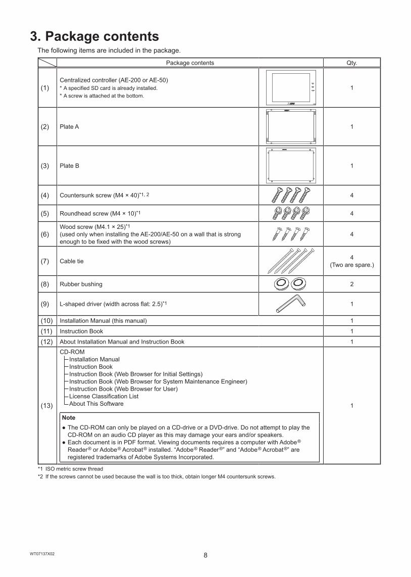
3. Package contentsThe following items are included in the package.
Package contents Qty.
(1) Centralized controller (AE-200 or AE-50) * A specified SD card is already installed. * A screw is attached at the bottom.
1
(2) Plate A 1
(3) Plate B 1
(4) Countersunk screw (M4 × 40)*1, 2 4
(5) Roundhead screw (M4 × 10)*1 4
(6) Wood screw (M4.1 × 25)*1(used only when installing the AE-200/AE-50 on a wall that is strong enough to be fixed with the wood screws)
4
(7) Cable tie 4(Two are spare.)
(8) Rubber bushing 2
(9) L-shaped driver (width across flat: 2.5)*1 1
(10) Installation Manual (this manual) 1
(11) Instruction Book 1
(12) About Installation Manual and Instruction Book 1
(13)
CD-ROM Installation Manual Instruction Book Instruction Book (Web Browser for Initial Settings) Instruction Book (Web Browser for System Maintenance Engineer) Instruction Book (Web Browser for User) License Classification List About This Software
Note ● The CD-ROM can only be played on a CD-drive or a DVD-drive. Do not attempt to play the CD-ROM on an audio CD player as this may damage your ears and/or speakers.
● Each document is in PDF format. Viewing documents requires a computer with Adobe® Reader® or Adobe® Acrobat® installed. “Adobe® Reader®” and “Adobe® Acrobat®” are registered trademarks of Adobe Systems Incorporated.
1
*1 ISO metric screw thread*2 If the screws cannot be used because the wall is too thick, obtain longer M4 countersunk screws.
9WT07137X02
Notes on the SD card installed on the AE-200/AE-50 ● The SD card installed on the AE-200/AE-50 has been set up at the factory. Do not use other SD cards as proper functioning cannot be guaranteed.
● The SD card installed on the AE-200/AE-50 differs from the ones sold on the market. ● The AE-200/AE-50 will not start up if the SD card does not function properly or is not installed. ● Only the SD card that has been formatted on AE-200/AE-50 can be used. ● Do not use the SD card installed on the AE-200/AE-50 for any other equipment. ● If the SD card becomes damaged, the AE-200/AE-50 energy management data will be lost. The AE-200/AE-50 settings data can be backed up from the AE-200/AE-50’s LCD or the Web browser to an external memory, and these data can be restored to the AE-200/AE-50. (Refer to the chapter [Maintenance] in the AE-200/AE-50 Instruction Book and the chapter [Utility] in the Instruction Book (Web Browser for Initial Settings) for details.) The energy management data can only be output in a CSV file, and these data cannot be restored to the AE-200/AE-50. (Refer to the chapter [Maintenance] in the Instruction Book (Web Browser for System Maintenance Engineer) for details.) It is recommended to back up these data periodically.
10WT07137X02
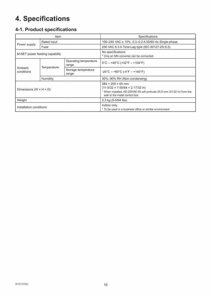
4. Specifications4-1. Product specifications
Item Specifications
Power supplyRated input 100–240 VAC ± 10%; 0.3–0.2 A 50/60 Hz Single-phaseFuse 250 VAC 6.3 A Time-Lag type (IEC 60127-2S.S.5)
M-NET power feeding capability No specifications * Only an MN converter can be connected.
Ambient conditions
Temperature
Operating temperature range 0°C – +40°C (+32°F – +104°F)
Storage temperature range -20°C – +60°C (-4°F – +140°F)
Humidity 30%–90% RH (Non-condensing)
Dimensions (W × H × D)
284 × 200 × 65 mm (11-5/32 × 7-55/64 × 2-17/32 in) * When installed, AE-200/AE-50 will protrude 25.0 mm (31/32 in) from the wall or the metal control box.
Weight 2.3 kg (5-5/64 lbs)
Installation conditions Indoor only * To be used in a business office or similar environment
11WT07137X02
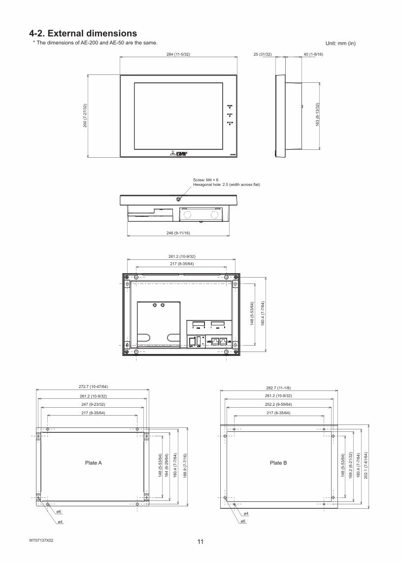
4-2. External dimensions * The dimensions of AE-200 and AE-50 are the same.
40 (1-9/16)25 (31/32)
163
(6-1
3/32
)
284 (11-5/32)
200
(7-2
7/32
)
202.
1 (7
-61/
64)
180.
4 (7
-7/6
4)
180.
4 (7
-7/6
4)
246 (9-11/16)
169.
2 (6
-21/
32)
148
(5-5
3/64
)
148
(5-5
3/64
)
261.2 (10-9/32)
217 (8-35/64)
282.7 (11-1/8)
261.2 (10-9/32)
252.2 (9-59/64)
217 (8-35/64)
Plate B
ø4
ø6
188.
9 (7
-7/1
6)
180.
4 (7
-7/6
4)
164
(6-2
9/64
)14
8 (5
-53/
64)
272.7 (10-47/64)
261.2 (10-9/32)
247 (9-23/32)
217 (8-35/64)
Plate A
ø6
ø4
Screw: M4 × 6Hexagonal hole: 2.5 (width across flat)
Unit: mm (in)
12WT07137X02
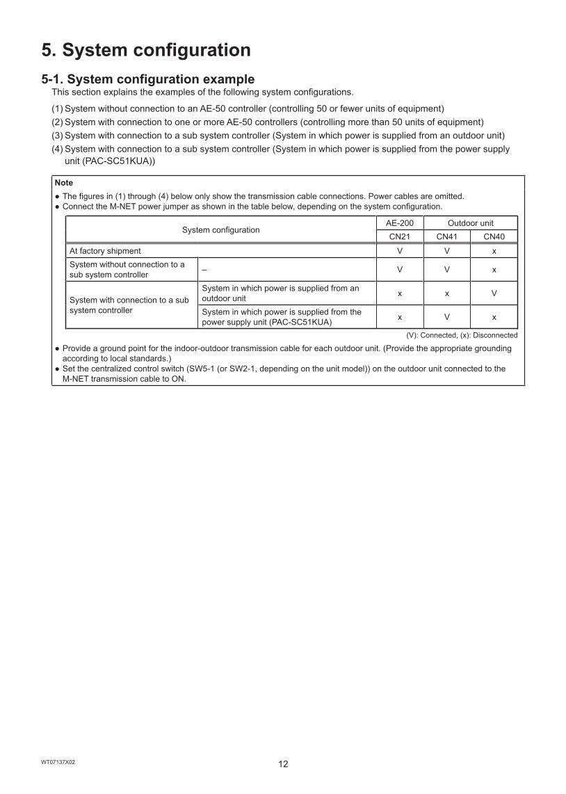
5. System configuration5-1. System configuration example
This section explains the examples of the following system configurations.
(1) System without connection to an AE-50 controller (controlling 50 or fewer units of equipment)(2) System with connection to one or more AE-50 controllers (controlling more than 50 units of equipment)(3) System with connection to a sub system controller (System in which power is supplied from an outdoor unit)(4) System with connection to a sub system controller (System in which power is supplied from the power supply
unit (PAC-SC51KUA))
Note ● The figures in (1) through (4) below only show the transmission cable connections. Power cables are omitted. ● Connect the M-NET power jumper as shown in the table below, depending on the system configuration.
System configurationAE-200 Outdoor unitCN21 CN41 CN40
At factory shipment V V xSystem without connection to a sub system controller – V V x
System with connection to a sub system controller
System in which power is supplied from an outdoor unit x x V
System in which power is supplied from the power supply unit (PAC-SC51KUA) x V x
(V): Connected, (x): Disconnected
● Provide a ground point for the indoor-outdoor transmission cable for each outdoor unit. (Provide the appropriate grounding according to local standards.)
● Set the centralized control switch (SW5-1 (or SW2-1, depending on the unit model)) on the outdoor unit connected to the M-NET transmission cable to ON.
13WT07137X02
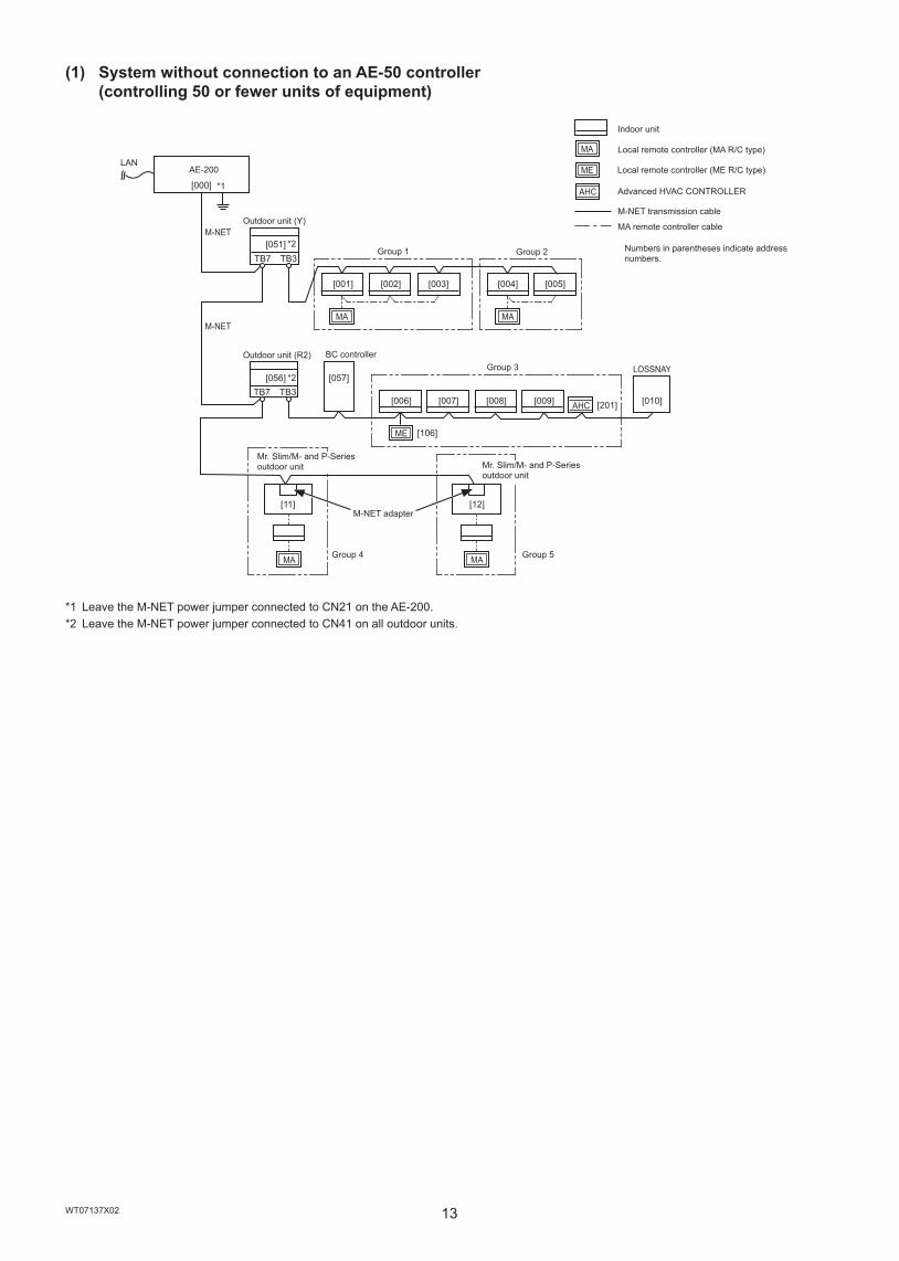
(1) System without connection to an AE-50 controller (controlling 50 or fewer units of equipment)
TB7 TB3
TB7 TB3
MAMA
ME
AHC
MA
LOSSNAY
[051]
[056] [057]
[000]
[004] [005][001] [002] [003]
[11] [12]
[006] [007] [008] [009] [010]
[106]
[201]
MA
M-NET
M-NET
AHC
MA
ME
*1 Leave the M-NET power jumper connected to CN21 on the AE-200.*2 Leave the M-NET power jumper connected to CN41 on all outdoor units.
LAN AE-200
*1
Outdoor unit (Y)
*2Group 1
Outdoor unit (R2)
*2
BC controller
Mr. Slim/M- and P-Series outdoor unit
Group 2
Group 3
M-NET adapter
Group 4
Mr. Slim/M- and P-Series outdoor unit
Indoor unit
Local remote controller (MA R/C type)
Local remote controller (ME R/C type)
Advanced HVAC CONTROLLER
M-NET transmission cable
MA remote controller cable
Numbers in parentheses indicate address numbers.
Group 5
14WT07137X02
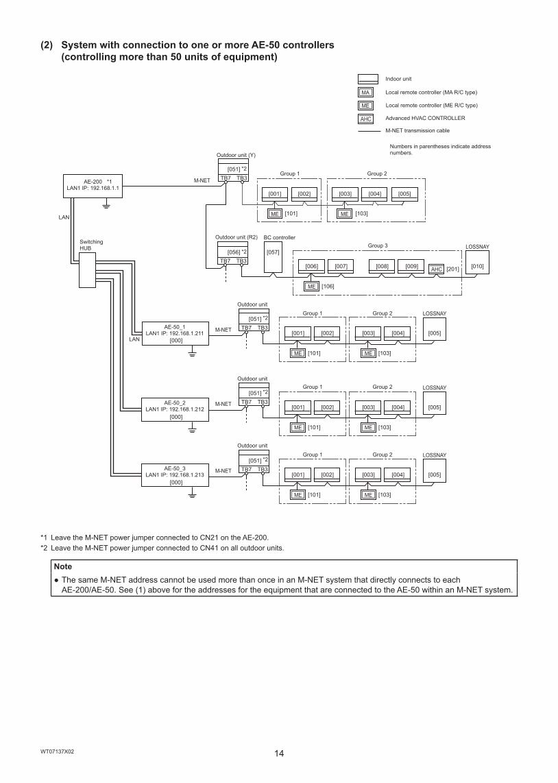
(2) System with connection to one or more AE-50 controllers (controlling more than 50 units of equipment)
TB7 TB3
TB7 TB3
ME ME
ME
[051]
[056] [057]
[001] [002] [003] [004] [005]
[006] [007] [008] [009] [010]
[106]
M-NET
M-NET
M-NET
TB7 TB3
ME
[051]
[001] [002] [003] [004] [005]
[101]
TB7 TB3
ME
[051]
[001] [002] [003] [004] [005]
[101]
ME [103]
[101] [103]
ME [103]
[000]
[000]
[000]
LOSSNAY
LOSSNAY
M-NET TB7 TB3
ME
[051]
[001] [002] [003] [004] [005]
[101] ME [103]
LOSSNAY
LOSSNAY
AHC [201]
AHC
MA
ME
*1 Leave the M-NET power jumper connected to CN21 on the AE-200.*2 Leave the M-NET power jumper connected to CN41 on all outdoor units.
Note ● The same M-NET address cannot be used more than once in an M-NET system that directly connects to each AE-200/AE-50. See (1) above for the addresses for the equipment that are connected to the AE-50 within an M-NET system.
AE-200LAN1 IP: 192.168.1.1
*1
LAN
Switching HUB
Outdoor unit (Y)
*2
Outdoor unit (R2)
Group 1
*2
AE-50_1LAN1 IP: 192.168.1.211
LAN
BC controller
Outdoor unit
Group 2
Group 3
*2Group 1
AE-50_2LAN1 IP: 192.168.1.212
Indoor unit
Local remote controller (MA R/C type)
Local remote controller (ME R/C type)
Advanced HVAC CONTROLLER
M-NET transmission cable
Outdoor unit
Numbers in parentheses indicate address numbers.
*2
Group 2
Group 1
AE-50_3LAN1 IP: 192.168.1.213
Outdoor unit
Group 2
*2Group 1 Group 2

15WT07137X02
(3) System with connection to a sub system controller (System in which power is supplied from an outdoor unit)
TB7 TB3
TB7 TB3
MA
[051]
[056] [057]
[000]
[11] [12]
MA
AHC
M-NET
M-NET
[202] MAMA
[004] [005][001] [002] [003]
ME
AHC
LOSSNAY
[006] [007] [008] [009] [010]
[106]
[201]
MA
ME
*1 Disconnect the M-NET power jumper (CN21) from the AE-200.*2 Move the M-NET power jumper from CN41 to CN40 on only one of the outdoor units.
LANAE-200
*1
Outdoor unit (Y)
*2Group 1
Outdoor unit (R2) BC controller
Mr. Slim/M- and P-Series outdoor unit
Group 2
Group 3
M-NET adapter
Group 4
Mr. Slim/M- and P-Series outdoor unit
Indoor unit
Local remote controller (MA R/C type)
Local remote controller (ME R/C type)
Sub system controller
Advanced HVAC CONTROLLER
M-NET transmission cable
MA remote controller cable
Numbers in parentheses indicate address numbers.
Group 5
16WT07137X02
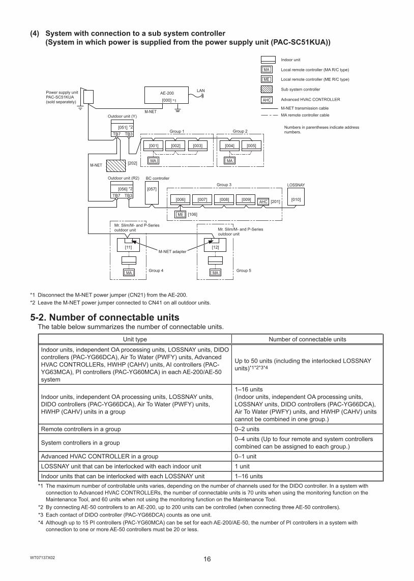
(4) System with connection to a sub system controller (System in which power is supplied from the power supply unit (PAC-SC51KUA))
TB7 TB3
TB7 TB3
MA
M-NET
[051]
[056] [057]
[000]
[11] [12]
MA
M-NET
ME
AHC
LOSSNAY
[006] [007] [008] [009] [010]
[106]
[201]
MAMA
[004] [005][001] [002] [003]
[202]
AHC
MA
ME
*1 Disconnect the M-NET power jumper (CN21) from the AE-200.*2 Leave the M-NET power jumper connected to CN41 on all outdoor units.
5-2. Number of connectable unitsThe table below summarizes the number of connectable units.
Unit type Number of connectable units
Indoor units, independent OA processing units, LOSSNAY units, DIDO controllers (PAC-YG66DCA), Air To Water (PWFY) units, Advanced HVAC CONTROLLERs, HWHP (CAHV) units, AI controllers (PAC-YG63MCA), PI controllers (PAC-YG60MCA) in each AE-200/AE-50 system
Up to 50 units (including the interlocked LOSSNAY units)*1*2*3*4
Indoor units, independent OA processing units, LOSSNAY units, DIDO controllers (PAC-YG66DCA), Air To Water (PWFY) units, HWHP (CAHV) units in a group
1–16 units(Indoor units, independent OA processing units, LOSSNAY units, DIDO controllers (PAC-YG66DCA), Air To Water (PWFY) units, and HWHP (CAHV) units cannot be combined in one group.)
Remote controllers in a group 0–2 units
System controllers in a group 0–4 units (Up to four remote and system controllers combined can be assigned to each group.)
Advanced HVAC CONTROLLER in a group 0–1 unitLOSSNAY unit that can be interlocked with each indoor unit 1 unitIndoor units that can be interlocked with each LOSSNAY unit 1–16 units
*1 The maximum number of controllable units varies, depending on the number of channels used for the DIDO controller. In a system with connection to Advanced HVAC CONTROLLERs, the number of connectable units is 70 units when using the monitoring function on the Maintenance Tool, and 60 units when not using the monitoring function on the Maintenance Tool.
*2 By connecting AE-50 controllers to an AE-200, up to 200 units can be controlled (when connecting three AE-50 controllers).*3 Each contact of DIDO controller (PAC-YG66DCA) counts as one unit.*4 Although up to 15 PI controllers (PAC-YG60MCA) can be set for each AE-200/AE-50, the number of PI controllers in a system with
connection to one or more AE-50 controllers must be 20 or less.
Power supply unit PAC-SC51KUA (sold separately)
Outdoor unit (Y)
*2
AE-200
Group 1
Outdoor unit (R2)
*1
*2
BC controller
Mr. Slim/M- and P-Series outdoor unit
Group 2
Group 3
M-NET adapter
Group 4
Indoor unit
Local remote controller (MA R/C type)
Local remote controller (ME R/C type)
Sub system controller
Mr. Slim/M- and P-Series outdoor unit
Advanced HVAC CONTROLLER
M-NET transmission cable
MA remote controller cable
Numbers in parentheses indicate address numbers.
Group 5
LAN
17WT07137X02
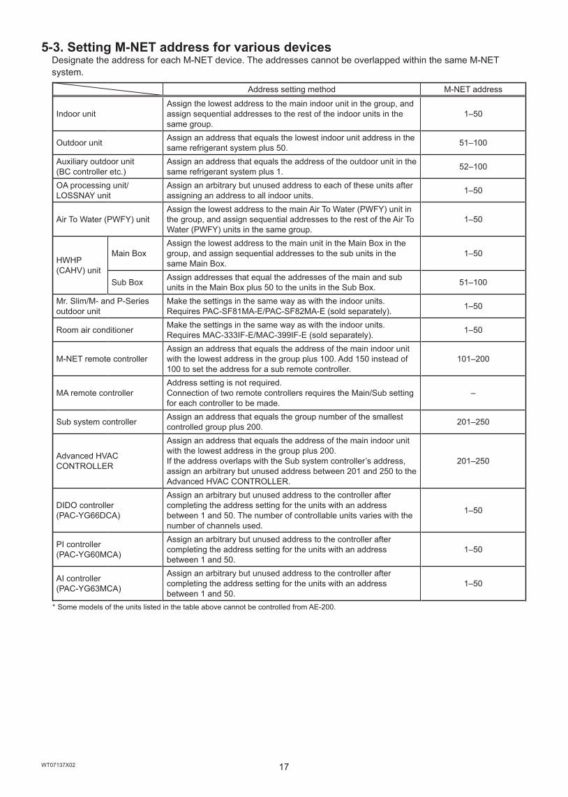
5-3. Setting M-NET address for various devicesDesignate the address for each M-NET device. The addresses cannot be overlapped within the same M-NET system.
Address setting method M-NET address
Indoor unitAssign the lowest address to the main indoor unit in the group, and assign sequential addresses to the rest of the indoor units in the same group.
1–50
Outdoor unit Assign an address that equals the lowest indoor unit address in the same refrigerant system plus 50. 51–100
Auxiliary outdoor unit(BC controller etc.)
Assign an address that equals the address of the outdoor unit in the same refrigerant system plus 1. 52–100
OA processing unit/LOSSNAY unit
Assign an arbitrary but unused address to each of these units after assigning an address to all indoor units. 1–50
Air To Water (PWFY) unitAssign the lowest address to the main Air To Water (PWFY) unit in the group, and assign sequential addresses to the rest of the Air To Water (PWFY) units in the same group.
1–50
HWHP (CAHV) unit
Main BoxAssign the lowest address to the main unit in the Main Box in the group, and assign sequential addresses to the sub units in the same Main Box.
1–50
Sub Box Assign addresses that equal the addresses of the main and sub units in the Main Box plus 50 to the units in the Sub Box. 51–100
Mr. Slim/M- and P-Series outdoor unit
Make the settings in the same way as with the indoor units.Requires PAC-SF81MA-E/PAC-SF82MA-E (sold separately). 1–50
Room air conditioner Make the settings in the same way as with the indoor units.Requires MAC-333IF-E/MAC-399IF-E (sold separately). 1–50
M-NET remote controllerAssign an address that equals the address of the main indoor unit with the lowest address in the group plus 100. Add 150 instead of 100 to set the address for a sub remote controller.
101–200
MA remote controllerAddress setting is not required.Connection of two remote controllers requires the Main/Sub setting for each controller to be made.
–
Sub system controller Assign an address that equals the group number of the smallest controlled group plus 200. 201–250
Advanced HVAC CONTROLLER
Assign an address that equals the address of the main indoor unit with the lowest address in the group plus 200. If the address overlaps with the Sub system controller’s address, assign an arbitrary but unused address between 201 and 250 to the Advanced HVAC CONTROLLER.
201–250
DIDO controller(PAC-YG66DCA)
Assign an arbitrary but unused address to the controller after completing the address setting for the units with an address between 1 and 50. The number of controllable units varies with the number of channels used.
1–50
PI controller(PAC-YG60MCA)
Assign an arbitrary but unused address to the controller after completing the address setting for the units with an address between 1 and 50.
1–50
AI controller(PAC-YG63MCA)
Assign an arbitrary but unused address to the controller after completing the address setting for the units with an address between 1 and 50.
1–50
* Some models of the units listed in the table above cannot be controlled from AE-200.
18WT07137X02
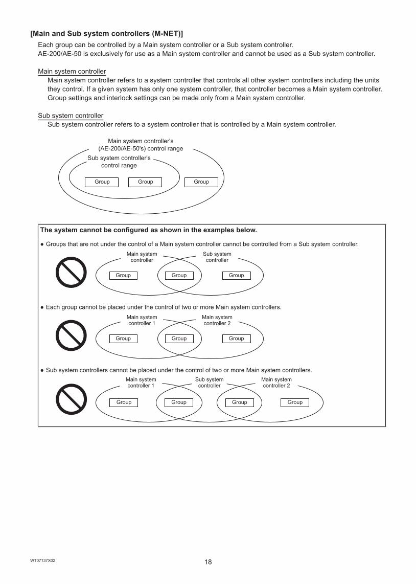
[Main and Sub system controllers (M-NET)]Each group can be controlled by a Main system controller or a Sub system controller. AE-200/AE-50 is exclusively for use as a Main system controller and cannot be used as a Sub system controller.
Main system controllerMain system controller refers to a system controller that controls all other system controllers including the units they control. If a given system has only one system controller, that controller becomes a Main system controller. Group settings and interlock settings can be made only from a Main system controller.
Sub system controllerSub system controller refers to a system controller that is controlled by a Main system controller.
The system cannot be configured as shown in the examples below.
● Groups that are not under the control of a Main system controller cannot be controlled from a Sub system controller.
● Each group cannot be placed under the control of two or more Main system controllers.
● Sub system controllers cannot be placed under the control of two or more Main system controllers.
Main system controller's (AE-200/AE-50's) control range
Group
Sub system controller's control range
Group Group
Group
Main system controller
Group
Sub system controller
Group
Group
Main system controller 1
Group
Main system controller 2
Group
Group
Main system controller 1
Group
Sub system controller
Group
Main system controller 2
Group
19WT07137X02
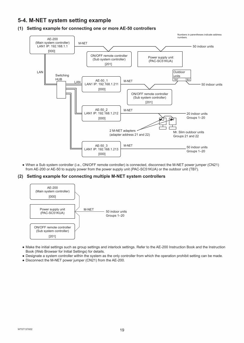
5-4. M-NET system setting example(1) Setting example for connecting one or more AE-50 controllers
[000]
[201]
M-NET
M-NET
M-NET
M-NET
[000]
[000]
[000]
[201]
TB7 TB3
● When a Sub system controller (i.e., ON/OFF remote controller) is connected, disconnect the M-NET power jumper (CN21) from AE-200 or AE-50 to supply power from the power supply unit (PAC-SC51KUA) or the outdoor unit (TB7).
(2) Setting example for connecting multiple M-NET system controllers
[000]
[201]
M-NET
● Make the initial settings such as group settings and interlock settings. Refer to the AE-200 Instruction Book and the Instruction Book (Web Browser for Initial Settings) for details.
● Designate a system controller within the system as the only controller from which the operation prohibit setting can be made. ● Disconnect the M-NET power jumper (CN21) from the AE-200.
AE-200(Main system controller)LAN1 IP: 192.168.1.1
LANSwitching HUB
LAN
ON/OFF remote controller(Sub system controller)
AE-50_1LAN1 IP: 192.168.1.211
AE-50_2LAN1 IP: 192.168.1.212
Power supply unit(PAC-SC51KUA)
AE-50_3LAN1 IP: 192.168.1.213
ON/OFF remote controller(Sub system controller)
2 M-NET adapters(adapter address 21 and 22)
Numbers in parentheses indicate address numbers.
50 indoor units
50 indoor units
Mr. Slim outdoor unitsGroups 21 and 22
20 indoor unitsGroups 1–20
50 indoor unitsGroups 1–20
Outdoor units
AE-200(Main system controller)
Power supply unit (PAC-SC51KUA)
ON/OFF remote controller(Sub system controller)
50 indoor unitsGroups 1–20

20WT07137X02
(3) Setting example for controlling Mr. Slim units (A-control models)
[000]
● An M-NET adapter (sold separately) is required to connect the Mr. Slim model of units to the M-NET. ● Leave the M-NET power jumper connected to CN21.
AE-200(Main system controller)
2 M-NET adapters(adapter address 21 and 22)
Mr. Slim outdoor unitsGroups 21 and 22
20 indoor unitsGroups 1–20

21WT07137X02
6. Installation
To reduce the risk of injury or electric shock, switch off the main power before performing electrical work.
To avoid malfunction, do not bundle power cables and signal cables together or place them in the same metallic conduit.
6-1. Installation methodsThe AE-200/AE-50 can be installed by any of the following installation methods.
Method 1 Wall-embedded installation(Refer to section 6-6-1 and 6-6-2 for installation procedures.)
Method 2 Wall-embedded installation with an electrical box(Refer to section 6-6-1 and 6-6-3 for installation procedures.)
Method 3 Installation on a metal control box(Refer to section 6-6-4 for installation procedures.)
Method 4 Installation inside a metal control box * Separately-sold mounting kit (PAC-YG86TK-J) is required. (The kit includes DIN rail attachments and L-fittings). Refer to the kit’s Installation Manual for installation procedures.
AE-200/AE-50
Wall
AE-200/AE-50
Electrical box PAC-YG84UTB-J (sold separately)
Wall
AE-200/AE-50
Metal control boxWall
AE-200/AE-50
Metal control box
DIN rail
Wall

22WT07137X02
6-2. Items not includedThe following items are required to install the AE-200/AE-50.
Items not included Specifications
Electrical box (required only for installation method 2)
Model: PAC-YG84UTB-J
Metal control box (required only for installation methods 3 and 4)
Must be suitable for the AE-200/AE-50 installation.Minimum metal thickness when using installation method 4: 200 mm (7-7/8 in)
Locknuts and bushing Must be suitable for the conduit tube to be used.
Sleeved ring terminalM3.5 ring terminal (for AC power cables (L/L1, N/L2) and M-NET transmission cables (A, B, S))M4 ring terminal (for protective ground wire)
AC power cable/Protective ground wire
Type: Sheathed vinyl wire (should not be lighter than ordinary PVC sheathed flexible cord IEC 60227.) (designation 60227 IEC 52)*1
Size: 0.75 to 2.00 mm² (ø1.0 to ø1.6 mm), AWG 18 to 14Protective ground wire color: green/yellow * Use a wire with an appropriate diameter so that the wire can be fixed with the cable tie below the terminal block. A diameter of 10 mm (25/64 in) is recommended.
Transmission cable
Type: Sheathed vinyl cable ● CPEVS ø1.2 to ø1.6 mm ● CVVS Min. 1.25 to 2 mm² * CPEVS: PE*2 insulated PVC*2 jacketed shielded communication cable * CVVS: PVC*2 insulated PVC*2 jacketed shielded control cable
LAN cable Category 5 or above straight cable (Max. 100 m (328 ft))Switching HUB A communication speed of 100 Mbps or faster is recommended.
Overcurrent breaker (fuse or circuit breaker)
Fuse Rated current: 3 A * When using a fuse, use it in combination with a switch (rated current: 3 A).
Circuit breakerType: Bipolar (2P2E)Contact distance: Min. 3 mm (1/8 in)Rated current: 3 A
Earth leakage breaker
Type: Bipolar (2P2E)Contact distance: Min. 3 mm (1/8 in)Rated current: 3 ARated current sensitivity: 30 mAOperation time: Max. 0.1 sec
*1 For the U.S. and Canada: designation NEC (NEPA70) or CEC*2 PE: Polyethylene, PVC: Polyvinyl chloride
6-3. Items sold separatelyItems sold separately Model name Remarks
Electrical box PAC-YG84UTB-J Required only for installation method 2
Mounting kitL-fittings
PAC-YG86TK-J Required only for installation method 4DIN rail attachments
External input/output adapter PAC-YG10HA-E Required when using the external input/output function
23WT07137X02
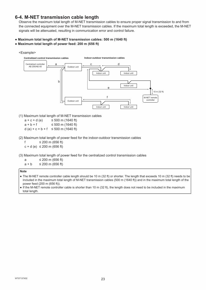
6-4. M-NET transmission cable lengthObserve the maximum total length of M-NET transmission cables to ensure proper signal transmission to and from the connected equipment over the M-NET transmission cables. If the maximum total length is exceeded, the M-NET signals will be attenuated, resulting in communication error and control failure.
● Maximum total length of M-NET transmission cables: 500 m (1640 ft)● Maximum total length of power feed: 200 m (656 ft)
<Example>
b
a c d
e
f
(1) Maximum total length of M-NET transmission cables a+c+d(e) ≤500m(1640ft) a+b+f ≤500m(1640ft) d(e)+c+b+f ≤500m(1640ft)
(2) Maximum total length of power feed for the indoor-outdoor transmission cables f ≤200m(656ft) c+d(e) ≤200m(656ft)
(3) Maximum total length of power feed for the centralized control transmission cables a ≤200m(656ft) a+b ≤200m(656ft)
Note ● The M-NET remote controller cable length should be 10 m (32 ft) or shorter. The length that exceeds 10 m (32 ft) needs to be included in the maximum total length of M-NET transmission cables (500 m (1640 ft)) and in the maximum total length of the power feed (200 m (656 ft)).
● If the M-NET remote controller cable is shorter than 10 m (32 ft), the length does not need to be included in the maximum total length.
Centralized control transmission cables
Centralized controller AE-200/AE-50 Outdoor unit
Outdoor unit
Indoor-outdoor transmission cables
Indoor unit
Indoor unit
Indoor unit
Indoor unit
Indoor unit
M-NET remote controller
10 m (32 ft)

24WT07137X02
6-5. Installation spaceLeave a space around the AE-200/AE-50 as shown in the figure below.
Note ● When installing two or more AE-200/AE-50 controllers side-by-side, leave a space of at least 30 mm (1-3/16 in) between them.
● When installing two or more AE-200/AE-50 controllers vertically, leave a space of at least 40 mm (1-37/64 in) between them. ● For the installation space for installation method 4, refer to the separately-sold mounting kit’s Installation Manual .
6-6. Installation proceduresNote
● Connect the necessary cables and wires before installing AE-200/AE-50, referring to chapters 7 and 10. ● Do not install the unit where the unit may continuously receive vibration. The continuous vibration may cause the connector pins to disconnect.
Important ● When routing the cable from above, let the cable hang loose behind the controller as shown in the figure below to prevent water from running down the cable into the connectors.
6-6-1. Cutting an installation hole and screw holes in the wall (Methods 1 and 2)Cut an installation hole (169 × 252 mm (6-21/32 × 9-59/64 in)) and screw holes in the wall as shown in the figure below.
Unit: mm (in)
30 (1
-3/1
6)284 (11-5/32)
30 (1-3/16)20
0 (7
-27/
32)
40 (1-37/64)
30 (1
-3/1
6)
Good example Bad example
Unit: mm (in)
180.
4 (7
-7/6
4)
252 (9-59/64)
ø6 (ø15/64)
217 (8-35/64)
169
(6-2
1/32
)
25WT07137X02
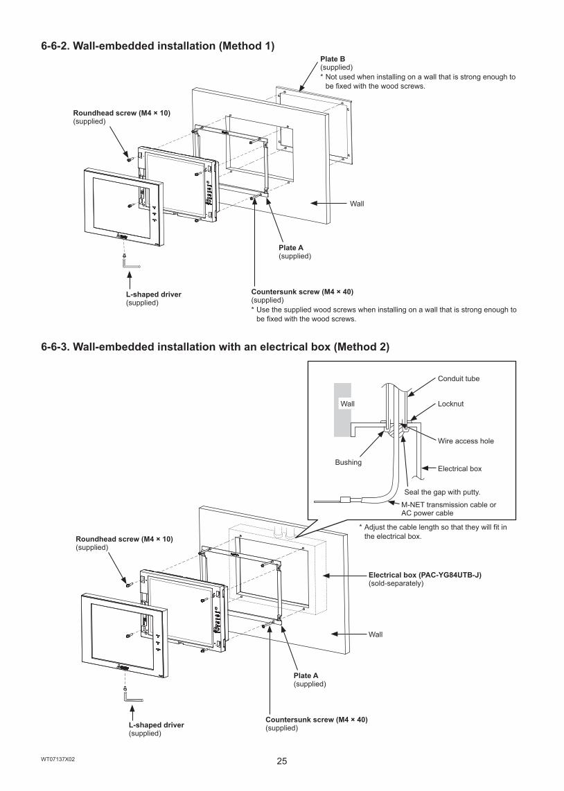
6-6-2. Wall-embedded installation (Method 1)
6-6-3. Wall-embedded installation with an electrical box (Method 2)
Roundhead screw (M4 × 10)(supplied)
L-shaped driver(supplied)
Plate B (supplied) * Not used when installing on a wall that is strong enough to be fixed with the wood screws.
Plate A (supplied)
Countersunk screw (M4 × 40)(supplied) * Use the supplied wood screws when installing on a wall that is strong enough to be fixed with the wood screws.
Wall
Roundhead screw (M4 × 10)(supplied)
Bushing
Wall
L-shaped driver(supplied)
Seal the gap with putty.
M-NET transmission cable or AC power cable
Electrical box (PAC-YG84UTB-J)(sold-separately)
Plate A (supplied)
Conduit tube
Locknut
Wire access hole
Electrical box
Countersunk screw (M4 × 40)(supplied)
Wall
* Adjust the cable length so that they will fit in the electrical box.
26WT07137X02
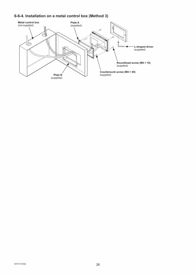
6-6-4. Installation on a metal control box (Method 3)Metal control box(not supplied)
Plate B(supplied)
Plate A (supplied)
Countersunk screw (M4 × 40)(supplied)
Roundhead screw (M4 × 10)(supplied)
L-shaped driver(supplied)
27WT07137X02
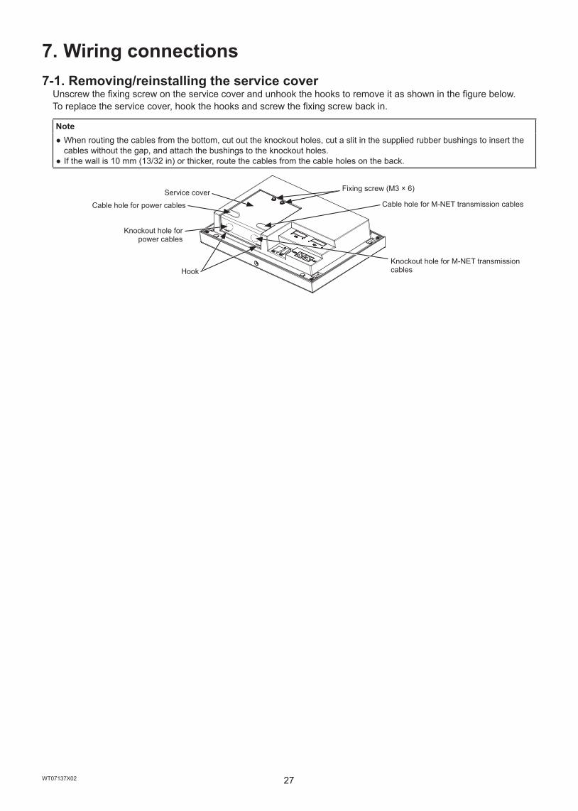
7. Wiring connections7-1. Removing/reinstalling the service cover
Unscrew the fixing screw on the service cover and unhook the hooks to remove it as shown in the figure below.To replace the service cover, hook the hooks and screw the fixing screw back in.
Note ● When routing the cables from the bottom, cut out the knockout holes, cut a slit in the supplied rubber bushings to insert the cables without the gap, and attach the bushings to the knockout holes.
● If the wall is 10 mm (13/32 in) or thicker, route the cables from the cable holes on the back.
Knockout hole for power cables
Service cover
Hook
Fixing screw (M3 × 6)
Knockout hole for M-NET transmission cables
Cable hole for power cables Cable hole for M-NET transmission cables

28WT07137X02
7-2. Connecting AC power cables and M-NET transmission cables(1) System without connection to an AE-50 controller
(controlling 50 or fewer units of equipment)
TB7
*1 Properly fix the cable sheaths in place with the supplied cable ties. The distance between the sheath end and the ring terminal must be 30 mm (1-3/16 in) or less.
Note ● The M-NET power jumper (CN21) needs to be connected or disconnected, depending on the system configuration. Refer to chapter 5 “System configuration” for details.
● Make the protective ground wire longer than the AC power cables (L/L1, N/L2). (Approximately 40 mm (1-37/64 in)) ● Use M3.5 ring terminals to connect the cables to the terminal blocks. ● Use an M4.0 ring terminal to connect the protective ground wire.
Cable tie*1
AE-200
M-NET transmission cables for centralized control
AC power cables
M-NET transmission cables A and B (Non-polarized)
M-NET transmission cable S (Shield)
AC power cables
Outdoor unit
Overcurrent breaker
To outdoor unit
Earth leakage breaker
Power supply100–240 VAC50/60 Hz
* When a sub system controller is connected (see section 5-1 (3) and (4)), disconnect the M-NET power jumper from CN21. (Refer to section 2-1 “Part names” for the location of CN21.)
100–240 VAC
Protective ground wire
30 mm (1-3/16 in) or less*1

29WT07137X02
(2) System with connection to one or more AE-50 controllers (controlling more than 50 units of equipment)
TB7
TB7
*1 Properly fix the cable sheaths in place with the supplied cable ties. The distance between the sheath end and the ring terminal must be 30 mm (1-3/16 in) or less.
Note ● The M-NET power jumper (CN21) needs to be connected or disconnected, depending on the system configuration. Refer to chapter 5 “System configuration” for details.
● Make the protective ground wire longer than the AC power cables (L/L1, N/L2). (Approximately 40 mm (1-37/64 in)) ● Use M3.5 ring terminals to connect the cables to the terminal blocks. ● Use an M4.0 ring terminal to connect the protective ground wire.
AE-200
M-NET transmission cables for centralized control
AC power cables
Overcurrent breakerEarth leakage breaker
AC power cables
Power supply100–240 VAC50/60 Hz
Outdoor unit
AE-50
Switching HUB
Overcurrent breaker
Earth leakage breaker
Power supply100–240 VAC50/60 Hz
M-NET transmission cables for centralized control
Outdoor unit
M-NET transmission cable S (Shield)
M-NET transmission cables A and B (Non-polarized)
AC power cables
Cable tie*1
To outdoor unit100–240 VAC
M-NET transmission cable S (Shield)
M-NET transmission cables A and B (Non-polarized)
AC power cablesTo outdoor unit100–240 VAC
Protective ground wire
Protective ground wire
Cable tie*1
30WT07137X02
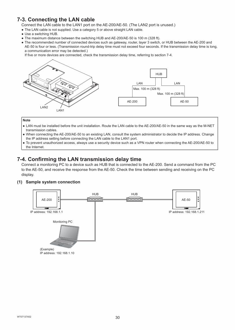
7-3. Connecting the LAN cableConnect the LAN cable to the LAN1 port on the AE-200/AE-50. (The LAN2 port is unused.)
● The LAN cable is not supplied. Use a category 5 or above straight LAN cable. ● Use a switching HUB. ● The maximum distance between the switching HUB and AE-200/AE-50 is 100 m (328 ft). ● The recommended number of connected devices such as gateway, router, layer 3 switch, or HUB between the AE-200 and AE-50 is four or less. (Transmission round-trip delay time must not exceed four seconds. If the transmission delay time is long, a communication error may be detected.) If five or more devices are connected, check the transmission delay time, referring to section 7-4.
AE-200 AE-50
Note ● LAN must be installed before the unit installation. Route the LAN cable to the AE-200/AE-50 in the same way as the M-NET transmission cables.
● When connecting the AE-200/AE-50 to an existing LAN, consult the system administrator to decide the IP address. Change the IP address setting before connecting the LAN cable to the LAN1 port.
● To prevent unauthorized access, always use a security device such as a VPN router when connecting the AE-200/AE-50 to the Internet.
7-4. Confirming the LAN transmission delay timeConnect a monitoring PC to a device such as HUB that is connected to the AE-200. Send a command from the PC to the AE-50, and receive the response from the AE-50. Check the time between sending and receiving on the PC display.
(1) Sample system connection
AE-200 AE-50
LAN2LAN1
LAN
Max. 100 m (328 ft)
HUB
Max. 100 m (328 ft)
LAN
IP address: 192.168.1.1
Monitoring PC
(Example) IP address: 192.168.1.10
HUB HUB
IP address: 192.168.1.211

31WT07137X02
(2) Checking the transmission delay time① Click [Start]>[Program]>[Accessories]>[Command Prompt] on the monitoring PC.② Enter [ping (IP address of AE-50)], and press the Enter button.
([ping -w 1000 192.168.1.211] is entered on the sample screen below.)③ Check that the transmission delay time that appears on the screen is 1000 ms or below.
(The transmission delay time is “Maximum = 2 ms” on the sample screen below, which is normal.) If [Request timed out] appears or the displayed transmission delay time exceeds 1000 ms, consult the network administrator for how to decrease the number of gateway, router, layer 3 switch, or HUB or how to change the network.
Note ● The IP address of the monitoring PC should not overlap any of the addresses that are assigned to the AE-200/AE-50. ● When connecting to an existing LAN system, which does not use a dedicated LAN, consult the network administrator to obtain the permission to connect the monitoring PC and the temporary IP address for the PC.
Enter [ping -w 1000 192.168.1.211], and press the Enter button.
Check the transmission delay time.The time should be 1000 ms or below.
If [Request timed out] appears, check the LAN connection status and IP address.

32WT07137X02
8. Initial settingsInitial settings need to be made for each AE-200 on the AE-200’s LCD or the Web browser. The table below explains how to make initial settings on the AE-200’s LCD. Details about the initial settings are covered in the AE-200 Instruction Book and the Instruction Book (Web Browser for Initial Settings).
The startup and initial setting procedures vary with the system configuration.System configuration 1: System without connection to AE-50 controller
(controlling 50 or fewer units of equipment)System configuration 2: System with connection to one or more AE-50 controllers
(controlling more than 50 units of equipment)
ProcedureSystem
configuration Details1 2
Start-up
① Turn on the power to the AE-50 controllers.
②Make initial settings for the AE-50 controllers on the [Unit Info.] and [Network] screens. * The AE-50 will restart.
① ③ Turn on the power to the AE-200.② ④ The language selection window will appear. Select the desired language.
③ ⑤
The [Initial Settings] screen will appear.(Once the initial settings have been made, the [Monitor/Operation] screen will appear when the unit is turned on. Touch the icon to bring up the [Initial Settings] screen if necessary.)
Date and time settings
① ① Set the current date and time.② ② Make other settings as necessary, and touch [Save Settings].
Unit information settings
① ① Touch the [Unit info.] tab in the [Initial Settings] menu.② Set the [System Exp] setting to [Do not expand].
② Set the [System Exp] setting to [Expand].③ ③ Make other settings as necessary, and touch [Save Settings].
Network settings
① ① Touch the [Network] tab in the [Initial Settings] menu.
②Set the AE-200’s IP address and other necessary settings, and touch [Save Settings]. * The AE-200 will restart.
②Make sure that [AE200] is selected as [Controller], set the AE-200’s IP address and other necessary settings, and touch [Save Settings]. * The AE-200 will restart.
③ Touch the [AE200] button to change it to [AE(1–3)], set the AE-50’s destination IP addresses and other necessary settings, and touch [Save Settings].
Group settings
① ① Touch the [Groups] tab in the [Initial Settings] menu.② Make group settings for AE-200, and touch [Save Settings].
② Make sure that [AE200] is selected as [Controller], make group settings for AE-200, and touch [Save Settings].
③ Touch the [AE200] button to change it to [AE(1–3)], make group settings for AE-50 controllers, and touch [Save Settings].
Other initial settings ① ①
Make the following settings as necessary. ● Interlock settings (interlocked operation between LOSSNAY and indoor units) ● Block settings ● Floor Layout settings ● User Information settings
Exiting the [Initial Settings] screen ① ① Touch the icon to return to the [Monitor/Operation] screen.

33WT07137X02
9. Test run9-1. Collective operation ON/OFF
Confirm that the group settings and interlock settings are complete before performing a test run.It may take approximately five minutes from power on until the local remote controllers become operable.Refer to the indoor unit Installation Manual for details about a test run.
Test run procedure(1) Turn on the power to the AE-200 and all units.(2) After the message [Please wait...] disappears, touch the [Unit info.] tab in the [Initial Settings] menu. Set the [Test
run] setting to [Use] to show the [Test Run] button on the operation settings screen under the [Monitor/Operation] menu. Touch the [Test Run] button on the operation settings window. The group of units will start an operation.
(3) Check for the proper operation of each unit during the test run (e.g., check to see if cold (or warm) air comes out of the supply air outlet on each indoor unit).
(4) After confirming that all units are operating properly, stop the units either from AE-200 or from the local remote controllers.
34WT07137X02
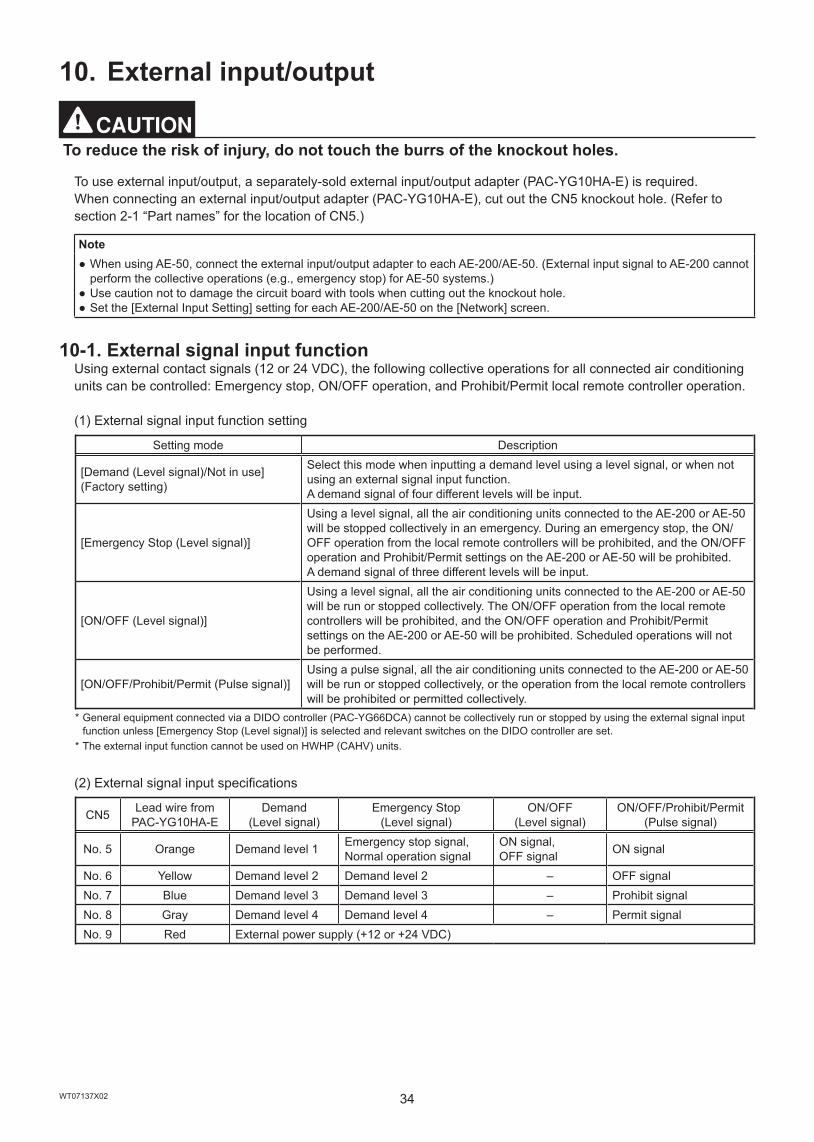
10. External input/output
To reduce the risk of injury, do not touch the burrs of the knockout holes.
To use external input/output, a separately-sold external input/output adapter (PAC-YG10HA-E) is required.When connecting an external input/output adapter (PAC-YG10HA-E), cut out the CN5 knockout hole. (Refer to section 2-1 “Part names” for the location of CN5.)
Note ● When using AE-50, connect the external input/output adapter to each AE-200/AE-50. (External input signal to AE-200 cannot perform the collective operations (e.g., emergency stop) for AE-50 systems.)
● Use caution not to damage the circuit board with tools when cutting out the knockout hole. ● Set the [External Input Setting] setting for each AE-200/AE-50 on the [Network] screen.
10-1. External signal input functionUsing external contact signals (12 or 24 VDC), the following collective operations for all connected air conditioning units can be controlled: Emergency stop, ON/OFF operation, and Prohibit/Permit local remote controller operation.
(1) External signal input function setting
Setting mode Description
[Demand (Level signal)/Not in use](Factory setting)
Select this mode when inputting a demand level using a level signal, or when not using an external signal input function.A demand signal of four different levels will be input.
[Emergency Stop (Level signal)]
Using a level signal, all the air conditioning units connected to the AE-200 or AE-50 will be stopped collectively in an emergency. During an emergency stop, the ON/OFF operation from the local remote controllers will be prohibited, and the ON/OFF operation and Prohibit/Permit settings on the AE-200 or AE-50 will be prohibited. A demand signal of three different levels will be input.
[ON/OFF (Level signal)]
Using a level signal, all the air conditioning units connected to the AE-200 or AE-50 will be run or stopped collectively. The ON/OFF operation from the local remote controllers will be prohibited, and the ON/OFF operation and Prohibit/Permit settings on the AE-200 or AE-50 will be prohibited. Scheduled operations will not be performed.
[ON/OFF/Prohibit/Permit (Pulse signal)]Using a pulse signal, all the air conditioning units connected to the AE-200 or AE-50 will be run or stopped collectively, or the operation from the local remote controllers will be prohibited or permitted collectively.
* General equipment connected via a DIDO controller (PAC-YG66DCA) cannot be collectively run or stopped by using the external signal input function unless [Emergency Stop (Level signal)] is selected and relevant switches on the DIDO controller are set.
* The external input function cannot be used on HWHP (CAHV) units.
(2) External signal input specifications
CN5 Lead wire from PAC-YG10HA-E
Demand (Level signal)
Emergency Stop (Level signal)
ON/OFF (Level signal)
ON/OFF/Prohibit/Permit (Pulse signal)
No. 5 Orange Demand level 1 Emergency stop signal, Normal operation signal
ON signal, OFF signal ON signal
No. 6 Yellow Demand level 2 Demand level 2 – OFF signalNo. 7 Blue Demand level 3 Demand level 3 – Prohibit signalNo. 8 Gray Demand level 4 Demand level 4 – Permit signalNo. 9 Red External power supply (+12 or +24 VDC)
35WT07137X02
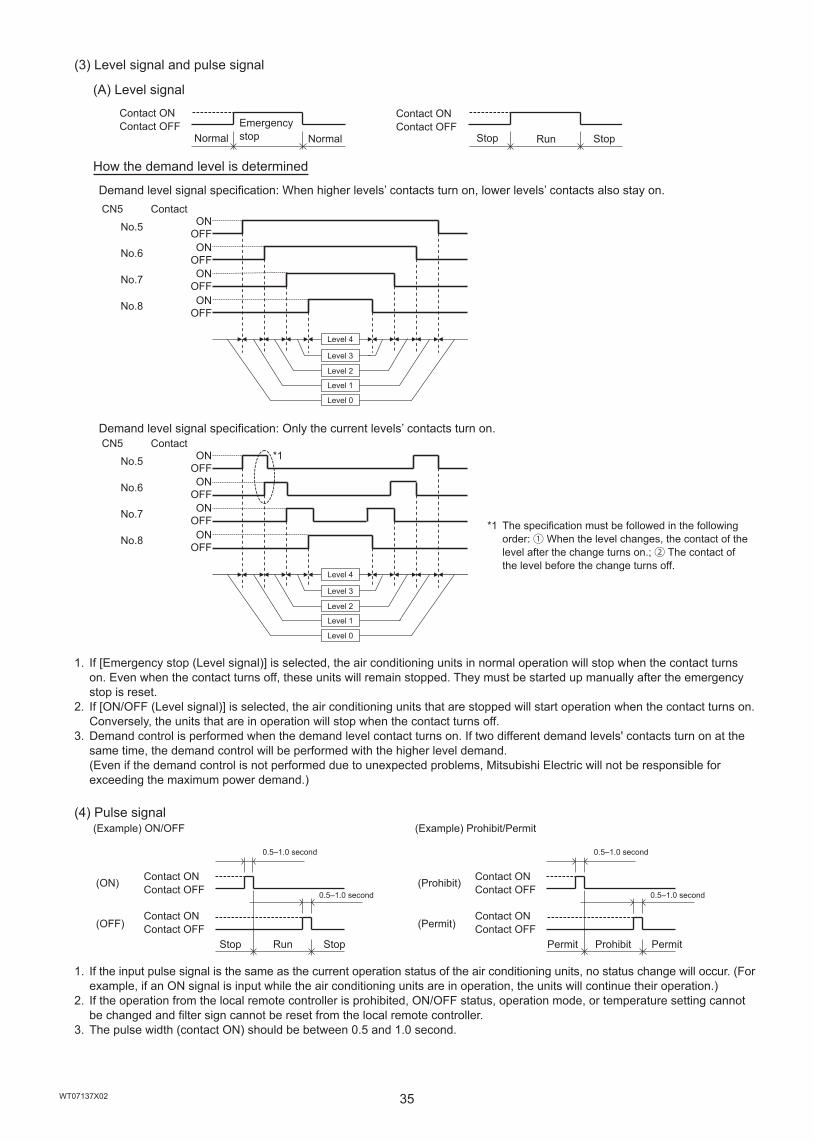
(3) Level signal and pulse signal
(A) Level signal
How the demand level is determined
Demand level signal specification: When higher levels’ contacts turn on, lower levels’ contacts also stay on.
Demand level signal specification: Only the current levels’ contacts turn on.
*1 The specification must be followed in the following order: ① When the level changes, the contact of the level after the change turns on.; ② The contact of the level before the change turns off.
1. If [Emergency stop (Level signal)] is selected, the air conditioning units in normal operation will stop when the contact turns on. Even when the contact turns off, these units will remain stopped. They must be started up manually after the emergency stop is reset.
2. If [ON/OFF (Level signal)] is selected, the air conditioning units that are stopped will start operation when the contact turns on. Conversely, the units that are in operation will stop when the contact turns off.
3. Demand control is performed when the demand level contact turns on. If two different demand levels' contacts turn on at the same time, the demand control will be performed with the higher level demand. (Even if the demand control is not performed due to unexpected problems, Mitsubishi Electric will not be responsible for exceeding the maximum power demand.)
(4) Pulse signal
1. If the input pulse signal is the same as the current operation status of the air conditioning units, no status change will occur. (For example, if an ON signal is input while the air conditioning units are in operation, the units will continue their operation.)
2. If the operation from the local remote controller is prohibited, ON/OFF status, operation mode, or temperature setting cannot be changed and filter sign cannot be reset from the local remote controller.
3. The pulse width (contact ON) should be between 0.5 and 1.0 second.
StopRunStop
Contact ONContact OFF
NormalEmergency stopNormal
Contact ONContact OFF
No.8 OFF
No.7
ONOFF
No.6
ONOFF
No.5
ONOFF
CN5 ContactON
Level 0
Level 1
Level 2
Level 3
Level 4
No.8 OFF
No.7
ONOFF
No.6
ONOFF
No.5
ONOFF
CN5 ContactON
Level 0
Level 1
Level 2
Level 3
Level 4
*1
0.5–1.0 second
Permit
0.5–1.0 second
ProhibitPermit
Contact ONContact OFF
Contact ONContact OFF
(Example) Prohibit/Permit
(Prohibit)
(Permit)
0.5–1.0 second
Stop
0.5–1.0 second
RunStop
(Example) ON/OFF
Contact ONContact OFF
Contact ONContact OFF
(ON)
(OFF)
36WT07137X02
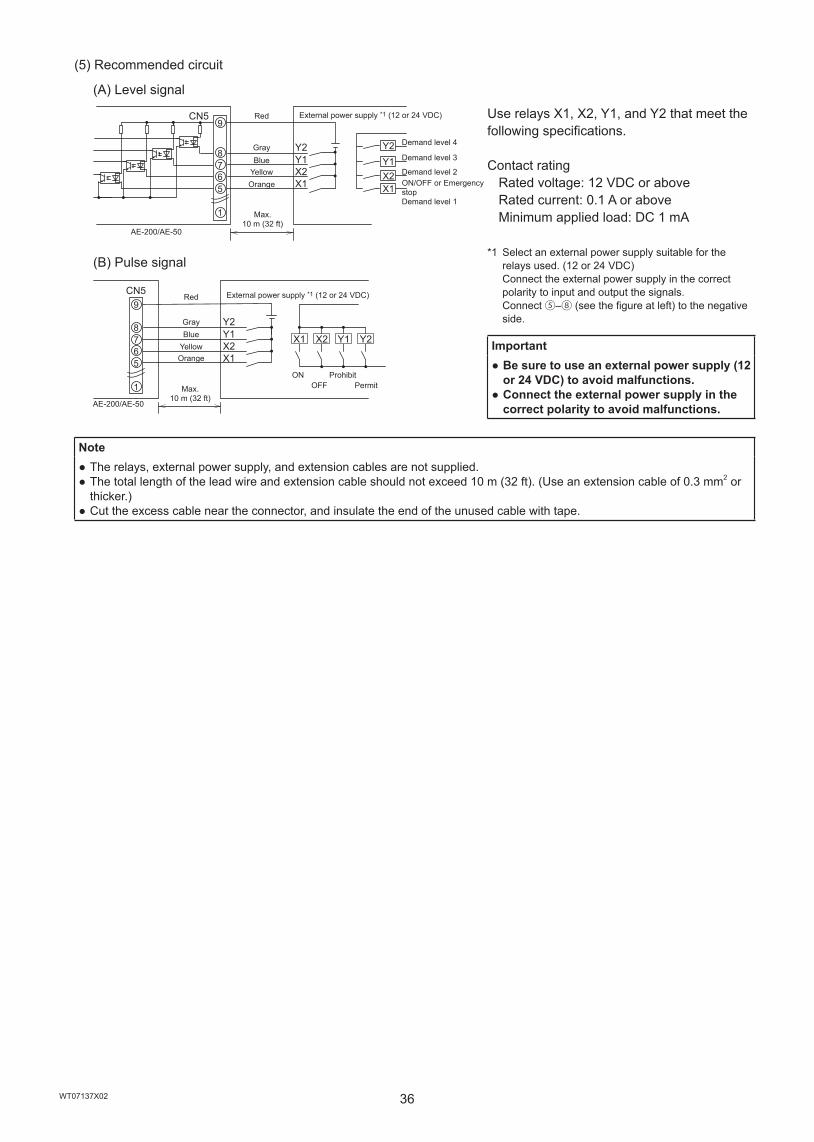
(5) Recommended circuit
(A) Level signal
CN5
X1X2Y1Y2
9
8765
1
X1X2Y1Y2
Use relays X1, X2, Y1, and Y2 that meet the following specifications.
Contact rating Rated voltage: 12 VDC or above Rated current: 0.1 A or above Minimum applied load: DC 1 mA
*1 Select an external power supply suitable for the relays used. (12 or 24 VDC) Connect the external power supply in the correct polarity to input and output the signals. Connect ⑤–⑧ (see the figure at left) to the negative side.
Important ● Be sure to use an external power supply (12 or 24 VDC) to avoid malfunctions.
● Connect the external power supply in the correct polarity to avoid malfunctions.
(B) Pulse signal
CN5
X1X2Y1Y2
X1 X2 Y1 Y2
9
8765
1
Note ● The relays, external power supply, and extension cables are not supplied. ● The total length of the lead wire and extension cable should not exceed 10 m (32 ft). (Use an extension cable of 0.3 mm2 or thicker.)
● Cut the excess cable near the connector, and insulate the end of the unused cable with tape.
ON/OFF or Emergency stopDemand level 1
Red
Orange
Max. 10 m (32 ft)
AE-200/AE-50
YellowBlueGray
External power supply *1 (12 or 24 VDC)
Demand level 2
Demand level 3
Demand level 4
PermitProhibit
OFFON
External power supply *1 (12 or 24 VDC)Red
GrayBlue
YellowOrange
Max. 10 m (32 ft)
AE-200/AE-50
37WT07137X02
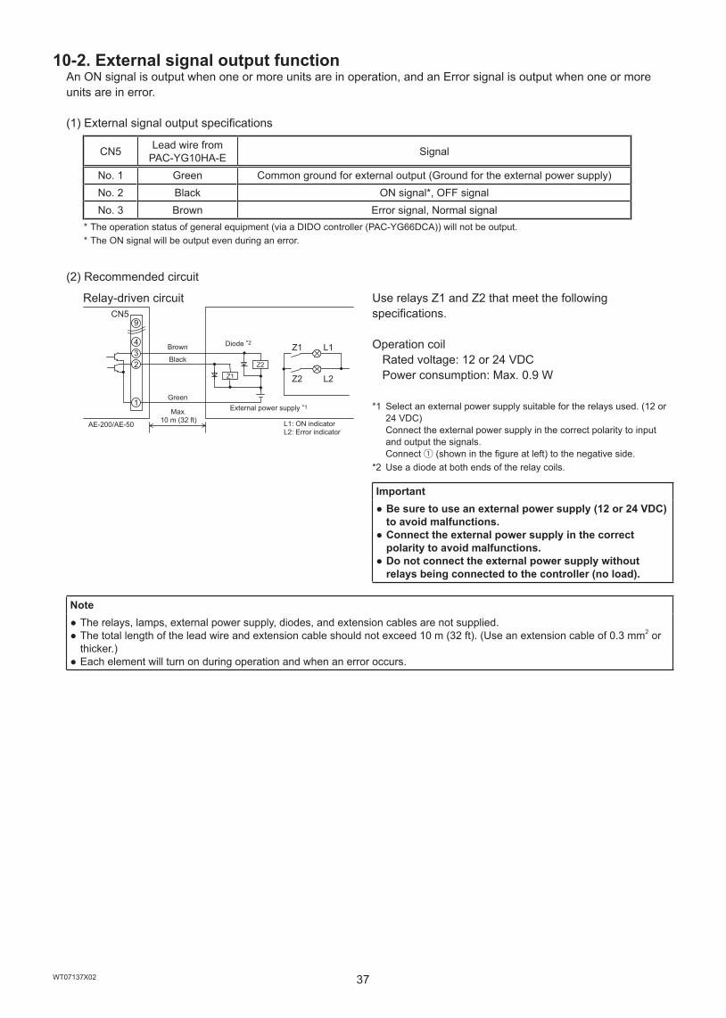
10-2. External signal output functionAn ON signal is output when one or more units are in operation, and an Error signal is output when one or more units are in error.
(1) External signal output specifications
CN5 Lead wire from PAC-YG10HA-E Signal
No. 1 Green Common ground for external output (Ground for the external power supply)No. 2 Black ON signal*, OFF signalNo. 3 Brown Error signal, Normal signal
* The operation status of general equipment (via a DIDO controller (PAC-YG66DCA)) will not be output. * The ON signal will be output even during an error.
(2) Recommended circuit
Relay-driven circuitCN5
4
9
32
1
Z1 L1
Z2 L2Z1
Z2
Use relays Z1 and Z2 that meet the following specifications.
Operation coil Rated voltage: 12 or 24 VDC Power consumption: Max. 0.9 W
*1 Select an external power supply suitable for the relays used. (12 or 24 VDC) Connect the external power supply in the correct polarity to input and output the signals. Connect ① (shown in the figure at left) to the negative side.
*2 Use a diode at both ends of the relay coils.
Important ● Be sure to use an external power supply (12 or 24 VDC) to avoid malfunctions.
● Connect the external power supply in the correct polarity to avoid malfunctions.
● Do not connect the external power supply without relays being connected to the controller (no load).
Note ● The relays, lamps, external power supply, diodes, and extension cables are not supplied. ● The total length of the lead wire and extension cable should not exceed 10 m (32 ft). (Use an extension cable of 0.3 mm2 or thicker.)
● Each element will turn on during operation and when an error occurs.
Green
Max. 10 m (32 ft)
Black
Brown
External power supply *1
Diode *2
L1: ON indicatorL2: Error indicator
AE-200/AE-50
38WT07137X02
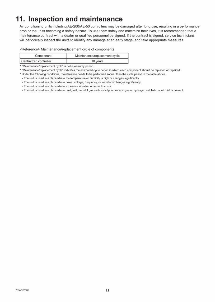
11. Inspection and maintenanceAir conditioning units including AE-200/AE-50 controllers may be damaged after long use, resulting in a performance drop or the units becoming a safety hazard. To use them safely and maximize their lives, it is recommended that a maintenance contract with a dealer or qualified personnel be signed. If the contract is signed, service technicians will periodically inspect the units to identify any damage at an early stage, and take appropriate measures.
<Reference> Maintenance/replacement cycle of components
Component Maintenance/replacement cycle
Centralized controller 10 years * “Maintenance/replacement cycle” is not a warranty period. * “Maintenance/replacement cycle” indicates the estimated cycle period in which each component should be replaced or repaired. * Under the following conditions, maintenance needs to be performed sooner than the cycle period in the table above.
- The unit is used in a place where the temperature or humidity is high or changes significantly. - The unit is used in a place where power voltage, frequency, or waveform changes significantly. - The unit is used in a place where excessive vibration or impact occurs. - The unit is used in a place where dust, salt, harmful gas such as sulphurous acid gas or hydrogen sulphide, or oil mist is present.
39WT07137X02
This equipment has been tested and found to comply with the limits for a Class B digital device, pursuant to Part 15 of the FCC Rules. These limits are designed to provide reasonable protection against harmful interference in a residential installation. This equipment generates, uses and can radiate radio frequency energy and, if not installed and used in accordance with the instructions, may cause harmful interference to radio communications.However, there is no guarantee that interference will not occur in a particular installation.If this equipment does cause harmful interference to radio or television reception, which can be determined by turning the equipment off and on, the user is encouraged to try to correct the interference by one or more of the following measures:
- Reorient or relocate the receiving antenna.- Increase the separation between the equipment and receiver.- Connect the equipment into an outlet on a circuit different from that to which the receiver is connected.- Consult the dealer or an experienced radio/TV technician for help.
SD and SDHC Logos are trademarks of SD-3C, LLC.
Java is a registered trademark of Oracle and/or its affiliates.
This product is designed and intended for use in the residential, commercial and light-industrial environment.
The product at hand is based on the following EU regulations:•Low Voltage Directive 2006/95/EC•Electromagnetic Compatibility Directive 2004/108/EC•Restriction of Hazardous Substances 2011/65/EU
Please be sure to put the contact address/telephone number on this manual before handing it to the customer.
HEAD OFFICE: TOKYO BLDG., 2-7-3, MARUNOUCHI, CHIYODA-KU, TOKYO 100-8310, JAPAN WT07137X02
872C595B10