air conditioning - clipsal...the damper control service accepts air conditioning demands (zone...
TRANSCRIPT

C-Bus Application Messages & Behaviour
Chapter 25 – Air Conditioning
Document Number: CBUS-APP/25
Issue: 1.12
Date: 26 August 2008
Comments on this document should be addressed to:
Engineering Manager Clipsal Integrated Systems PO Box 103 Hindmarsh South Australia 5007

Clipsal Australia Pty Ltd Document: CBUS-APP/25 ABN 27 007 873 529 Issue: Date:
C-Bus Air Conditioning Application
1.12 26 August 2008
Copyright © 2005 - 2008 Clipsal Australia Pty Ltd Page 2 of 45
TABLE OF CONTENTS 25 Air Conditioning Application ............................................................................................4
25.1 Application ID.........................................................................................................4 25.2 Definitions ..............................................................................................................4 25.3 Description.............................................................................................................4
25.3.1 Overview..................................................................................................4 25.3.2 Description of Services ............................................................................5
25.3.2.1 Plant Control ................................................................................6 25.3.2.2 Zone Manager .............................................................................6 25.3.2.3 User Interface ..............................................................................6 25.3.2.4 Schedule......................................................................................6 25.3.2.5 Time Service................................................................................7 25.3.2.6 Temperature Measurement .........................................................7 25.3.2.7 Humidity Measurement................................................................7
25.3.3 Example Installations...............................................................................7 25.3.3.1 Stand-alone Thermostat ..............................................................7 25.3.3.2 Wall Control with Relay Unit ........................................................7 25.3.3.3 Wall Control with Appliance Control and Zone Dampers.............8
25.3.4 Limitations................................................................................................8 25.4 Document Convention .........................................................................................10 25.5 Data Conventions ................................................................................................10
25.5.1 Specifying Temperatures .......................................................................10 25.5.2 Specifying Humidity ...............................................................................10 25.5.3 Specifying Raw Levels...........................................................................10 25.5.4 The Auxiliary Level.................................................................................11
25.6 Network Variables................................................................................................11 25.6.1 Zone HVAC Network Variables..............................................................12 25.6.2 Zone Humidity Network Variables..........................................................12 25.6.3 HVAC Mode and Flags ..........................................................................12 25.6.4 HVAC Type............................................................................................13 25.6.5 HVAC Errors ..........................................................................................14 25.6.6 HVAC Status Flags................................................................................14 25.6.7 Humidity Mode and Flags ......................................................................14 25.6.8 Humidity Type........................................................................................15 25.6.9 Humidity Errors ......................................................................................16 25.6.10 Humidity Status Flags ............................................................................16 25.6.11 Auxiliary Level........................................................................................17 25.6.12 Sensor Status ........................................................................................17 25.6.13 Zone Identification..................................................................................18
25.6.13.1 The Unswitched Zone..............................................................18 25.6.13.2 Zone Groups and Zone Lists ...................................................18
25.6.14 Schedule Information .............................................................................18 25.6.14.1 Start Times ..............................................................................18 25.6.14.2 Set Levels................................................................................18 25.6.14.3 Entry ........................................................................................19 25.6.14.4 Schedule Formats ...................................................................19
25.7 Air Conditioning Application Message Structure..................................................20 25.7.1 Short Form Commands..........................................................................20 25.7.2 Long Form Commands ..........................................................................21
25.8 Defined Commands .............................................................................................22 25.8.1 HVAC Schedule Entry............................................................................22

Clipsal Australia Pty Ltd Document: CBUS-APP/25 ABN 27 007 873 529 Issue: Date:
C-Bus Air Conditioning Application
1.12 26 August 2008
Copyright © 2005 - 2008 Clipsal Australia Pty Ltd Page 3 of 45
25.8.2 Humidity Schedule Entry........................................................................23 25.8.3 Refresh ..................................................................................................24 25.8.4 Zone HVAC Plant Status .......................................................................24 25.8.5 Zone Humidity Plant Status ...................................................................25 25.8.6 Zone Temperature .................................................................................26 25.8.7 Zone Humidity........................................................................................27 25.8.8 Set Zone Group Off................................................................................27 25.8.9 Set Zone Group On................................................................................28 25.8.10 Set Zone HVAC Mode ...........................................................................28 25.8.11 Set Plant HVAC Level............................................................................29 25.8.12 Set Zone Humidity Mode .......................................................................30 25.8.13 Set Plant Humidity Level........................................................................31 25.8.14 Set HVAC Upper Guard Limit ................................................................31 25.8.15 Set HVAC Lower Guard Limit ................................................................32 25.8.16 Set HVAC Setback Limit ........................................................................32 25.8.17 Set Humidity Upper Guard Limit ............................................................33 25.8.18 Set Humidity Lower Guard Limit ............................................................33 25.8.19 Set Humidity Setback Limit ....................................................................34
25.9 Message Priority ..................................................................................................34 25.10 Internetwork Routing............................................................................................34 25.11 Status Reporting ..................................................................................................34 25.12 Application & Device Behaviour...........................................................................35
25.12.1 Concatenated Commands .....................................................................35 25.12.2 State.......................................................................................................35 25.12.3 Power on (after power failure)................................................................35 25.12.4 The “Fan Coil” Plant Type......................................................................35 25.12.5 Mode......................................................................................................35 25.12.6 Set-Level................................................................................................36 25.12.7 Comfort Level.........................................................................................36 25.12.8 Fan Speed .............................................................................................36 25.12.9 To Monitor an HVAC System.................................................................36 25.12.10 Controlling an HVAC System.............................................................38 25.12.11 Making a Thermostat Mimic Panel / Controller ..................................39

Clipsal Australia Pty Ltd Document: CBUS-APP/25 ABN 27 007 873 529 Issue: Date:
C-Bus Air Conditioning Application
1.12 26 August 2008
Copyright © 2005 - 2008 Clipsal Australia Pty Ltd Page 4 of 45
25 AIR CONDITIONING APPLICATION
25.1 Application ID $AC
25.2 Definitions
Active Zone A Zone is one which is enabled, or not switched off, and which is therefore being controlled by the HVAC system. If the zoNe is currently close to the Set Point temperature, it is possible (but unusual) that the Damper may be closed and the Zone is not currently receiving any air flow
Damper A valve which controls the air flow to a Zone
Guard A safety override to protect a Zone from over or under temperature
HVAC Heating, Ventilation, Air Conditioning
Set-back Controlling to a range rather than a specific level
Set Point The desired temperature or Humidity which should be maintained in a Zone
Zone An air conditioned space that can be individually controlled
Zone Group A collection of zones that are controlled as a group
25.3 Description The C-Bus Air Conditioning Application is used to control and monitor air conditioners using a C-Bus network.
This document describes a protocol that suits virtually any HVAC application.
25.3.1 Overview The challenge in creating a protocol for HVAC control is the diversity of uses, devices, installation architecture, plant types and communications systems.
While the RWG connection standard is the most universally adopted, it has limitations and covers probably less than half of the total HVAC market world wide.
The protocol described in this document is independent of the installation and control standard. It introduces the notion of a Zone of space that is climate controlled. Each Zone has a number of attributes that define its state and capabilities. It also has a number of services that can modify the operating state based on its capabilities. A complete HVAC system is just a collection of several Zones
Being technology-neutral, the protocol allows equipment to be controlled using the RWG connection standard, or any other standard by development of an appropriate interface device.
Figure 25-1 and Figure 25-2 show examples of the essential elements for an HVAC installation.

Clipsal Australia Pty Ltd Document: CBUS-APP/25 ABN 27 007 873 529 Issue: Date:
C-Bus Air Conditioning Application
1.12 26 August 2008
Zone nCurrent TemperatureSet PointOperating ModeOutput Level
Zone ...Current TemperatureSet PointOperating ModeOutput Level
Zone 2Current TemperatureSet PointOperating ModeOutput Level
Zone 1Current TemperatureCurrent HumiditySet PointOperating ModeOutput Level
Figure 25-1 Example - Zones and Attributes
Temperature Measurement
Zone Manager Plant ControllerSchedule
Service
Time Service
Humidity Measurement
User Interface
Current Temperature
Set Point Operating Mode Output Level
Current HumidityZone 1
Damper Control
Figure 25-2 Service and Attribute Interaction
25.3.2 Description of Services The services are responsible for maintaining all the Zone attributes and thereby controlling the HVAC system. These services are software entities only and may be
Copyright © 2005 - 2008 Clipsal Australia Pty Ltd Page 5 of 45

Clipsal Australia Pty Ltd Document: CBUS-APP/25 ABN 27 007 873 529 Issue: Date:
C-Bus Air Conditioning Application
1.12 26 August 2008
Copyright © 2005 - 2008 Clipsal Australia Pty Ltd Page 6 of 45
physically located in any of the hardware on the system. The function, location and configuration of these services depends on the specific installation.
The Zone attributes are all C-Bus Network Variables. If a service changes the value of a Network Variable, it must do so using the commands described in this document. The only exception to this is where the Network Variables are purely internal to a C-Bus device and no other device on the network requires this information.
25.3.2.1 Plant Control The Plant Control service manages the physical hardware associated with it. Unlike many of the other services, the Plant Control service is strongly bound to the physical plant to ensure the correct control.
The Plant Control service accepts Air Conditioning demands (Zone Output level) and drives the physical plant accordingly.
There may be several Plant Controllers on the system.
25.3.2.1.1 Damper Control The Damper Control service ensures that active Zones have the dampers open while for inactive Zones, the dampers are closed. Frequently this service will reside the same hardware as the Plant Control service.
The Damper Control service accepts Air Conditioning demands (Zone Output level) and drives the dampers accordingly.
25.3.2.2 Zone Manager The Zone Manager service does the bulk of the work in the Air Conditioning system. It is responsible for ensuring that the Zones are kept at the comfort levels set for them. Usually this is a matter of using the Operating Mode, Set Point and Temperature information to drive the Air Conditioning level in such a manner that the temperature is held at around the set point.
Typically the Zone Manager is responsible for several Zones on the system. Humidity is controlled in the same manner.
25.3.2.3 User Interface The User Interface allows the user to set up and control the system and display relevant information. Typically the user interface will display the room temperature, allow changes to the set temperature, define active zones and set up the Program in the Schedule service.
The User Interface has no commands or network variables associated with it. It merely acts as an interface between the user and the network variables on the system.
25.3.2.4 Schedule The Schedule service stores a Program defining the Comfort levels for each zone for a particular time period.
When the system is operating under the control of the Schedule service, the Zone attributes are obtained from the Schedule rather than the User Interface.
Clipsal Australia Pty Ltd Document: CBUS-APP/25 ABN 27 007 873 529 Issue: Date:
C-Bus Air Conditioning Application
1.12 26 August 2008
25.3.2.5 Time Service The Time service comprises a real-time clock, which can be updated using the C-Bus Date & Time Application (as described in CBUS-APP/23). It simply provides a time of day function.
This service can act as a C-Bus Date & Time Master, provided the drift is less than about 15 minutes per year..
25.3.2.6 Temperature Measurement The Temperature Measurement service provides the system with information on the temperature of the Zone to which it is allocated.
The physical location of the sensor used to provide measurement to the Temperature Measurement service is not important.
25.3.2.7 Humidity Measurement Similarly to the Temperature Service, this service provides information on the Humidity in the zones.
The physical location of the sensor used to provide measurement to the Humidity Measurement service is not important.
25.3.3 Example Installations The diversity of HVAC installations makes it impossible to define a rigid set of implementation rules but the following examples help to illustrate the philosophy.
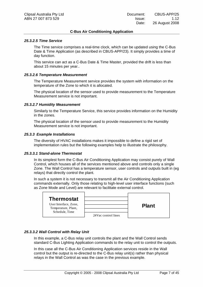
25.3.3.1 Stand-alone Thermostat In its simplest form the C-Bus Air Conditioning Application may consist purely of Wall Control, which houses all of the services mentioned above and controls only a single Zone. The Wall Control has a temperature sensor, user controls and outputs built in (eg relays) that directly control the plant.
In such a system it is not necessary to transmit all the Air Conditioning Application commands externally. Only those relating to high-level user interface functions (such as Zone Mode and Level) are relevant to facilitate external control.
Thermostat User Interface, Zone, Temperature, Plant,
Schedule, Time Plant
24Vac control lines
25.3.3.2 Wall Control with Relay Unit In this example, a C-Bus relay unit controls the plant and the Wall Control sends standard C-Bus Lighting Application commands to the relay unit to control the outputs.
In this case all the C-Bus Air Conditioning Application services reside in the Wall control but the output is re-directed to the C-Bus relay unit(s) rather than physical relays in the Wall Control as was the case in the previous example.
Copyright © 2005 - 2008 Clipsal Australia Pty Ltd Page 7 of 45

Clipsal Australia Pty Ltd Document: CBUS-APP/25 ABN 27 007 873 529 Issue: Date:
C-Bus Air Conditioning Application
1.12 26 August 2008
Once again, only a limited set of commands need appear on the C-Bus network.
Thermostat User Interface, Zone, Temperature, Plant,
Schedule, Time
C-Bus Relay Module C-Bus
Plant
Mains control lines
25.3.3.3 Wall Control with Appliance Control and Zone Dampers This example represents a more complex extreme. It consists of several Wall Controls, a heating appliance control, a cooling appliance control and possibly a separate Zone Damper control unit.
The Wall Control houses the Temperature, User Interface, Zone and Schedule services.
The appliance controls house their own Plant Control services and the Damper control houses the Damper service
In this case virtually all the Air Conditioning Application commands must appear on the C-Bus network.
T/stat 1 User Interface, Zone Manager, Temperature,
Schedule, Time C-Bus
Damper Drive Damper Control
T/stat 2 User Interface, Zone Manager, Temperature,
Schedule, Time
Cooling Plant
Plant Control
Heating Plant
Plant Control
25.3.4 Limitations The current protocol has the following limitations:
Copyright © 2005 - 2008 Clipsal Australia Pty Ltd Page 8 of 45

Clipsal Australia Pty Ltd Document: CBUS-APP/25 ABN 27 007 873 529 Issue: Date:
C-Bus Air Conditioning Application
1.12 26 August 2008
Copyright © 2005 - 2008 Clipsal Australia Pty Ltd Page 9 of 45
• Only temperature humidity, and ventilation can be controlled;
• For temperature control, a Zone must be either off, Heating, Cooling or Automatically switching between Heating and Cooling;
• For humidity control, a Zone must be either off, Humidifying, De-Humidifying or Automatically switching between Humidifying and De-Humidifying;
• There is only one operating mode and output level per Zone.
• It is not possible to have independent control of more than one type of plant in any given Zone; and
• Each Zone can only have one source of temperature or humidity measurement.

Clipsal Australia Pty Ltd Document: CBUS-APP/25 ABN 27 007 873 529 Issue: Date:
C-Bus Air Conditioning Application
1.12 26 August 2008
Copyright © 2005 - 2008 Clipsal Australia Pty Ltd Page 10 of 45
25.4 Document Convention Numbers are shown in decimal (base ten) with no other special prefixes or indications.
Binary numbers (base 2) are shown with the prefix %.
Hexadecimal numbers (base 16) are shown with the prefix $.
Example: 157 = %10011101 = $9D
25.5 Data Conventions
25.5.1 Specifying Temperatures All temperatures are transferred over C-Bus in ºC. To use with ºF, the following conversions can be used:
ºF = ºC * 9 / 5 + 32
ºC = (ºF – 32) * 5 / 9
All temperatures (room and set point) are transmitted using the same convention:
The temperature is transferred as a signed 2's complement integer using two bytes. The value represents the temperature expressed in 256th of a degree. The following examples indicate the conventions:
Temperature = 25.3°C
Value = Integer(25.3 * 256) = $194C Hex
Temperature = -37.9°C
Value = Integer(-37.9 * 256) = $DA1A Hex
25.5.2 Specifying Humidity All Humidity values are transferred over C-Bus in %, expressed as a two bytes representing the Humidity (0 = 0% to 65535 = 100%).
25.5.3 Specifying Raw Levels In some modes, the set level is neither Temperature nor Humidity. In this case, the level is expressed as a fraction of the capacity of the plant, using 2 bytes as a signed 2's complement number1:
In this case:
Raw Level = 50%
Value = Integer(0.5 * 32767) = $3FFF Hex
Raw Level = -10%
Value = - Integer(0.1 * 32768) = $F334 Hex
1 Raw Level is used (for example) for Evaporative control in non-thermostatic mode.

Clipsal Australia Pty Ltd Document: CBUS-APP/25 ABN 27 007 873 529 Issue: Date:
C-Bus Air Conditioning Application
1.12 26 August 2008
25.5.4 The Auxiliary Level When HVAC Mode or Level is set, each command carries the level and an Auxiliary Level. Auxiliary Level conveys Fan speed and mode, and allows future expansion for additional plant-dependant information.
The Auxiliary Level is not normally used in automatic operating modes, where a plant controller works out how to run based on the demand placed upon it.
Typically the Auxiliary Level is used to set a manual fan speed and set the Fan Mode.
When the Flags indicate that the Auxiliary Level is not used, it means that whatever is controlled by the Auxiliary Level is to operate automatically.
25.6 Network Variables This application utilises a common set of data known as Network Variables. This data set characterises the behaviour of the C-Bus Air Conditioning Application. Network Variables are available to all devices on the system and are accessed and modified by the set of commands defined in this document.
Air Conditioning Application Network Variables are arranged into a hierarchy, as shown in Figure 25-3.
...
Mode
Set Level
etc
HVAC
Mode
Set Level
etc
Humidity
Zone
Zone
Zone
Zone Group
Figure 25-3 Network Variable Hierarchy
Copyright © 2005 - 2008 Clipsal Australia Pty Ltd Page 11 of 45

Clipsal Australia Pty Ltd Document: CBUS-APP/25 ABN 27 007 873 529 Issue: Date:
C-Bus Air Conditioning Application
1.12 26 August 2008
Copyright © 2005 - 2008 Clipsal Australia Pty Ltd Page 12 of 45
25.6.1 Zone HVAC Network Variables The Zone HVAC Network variables characterise the Heating, Cooling or Ventilation state of a individual zone. There is a set of Zone Network variables for each individual zone on the system.
Variable Function HVAC Mode Mode of operation in the zone (see 25.6.3) HVAC Set Level Set temperature or operating level HVAC Setback Level The allowable variation from the set level HVAC Type Type of HVAC plant (see 25.6.3) HVAC Flags Defines how the zone is to be controlled (see 25.6.3) HVAC Guard Maximum Maximum allowable temperature HVAC Guard Minimum Minimum allowable temperature HVAC Output Level The HVAC output required of the plant for that zone HVAC Auxiliary Level A second level needed for some plant types Current Temperature The temperature in the zone HVAC Status Information on the system function (see 25.6.5) Sensor Status Information on the operation of a sensor (see 25.6.12) HVAC Error A code representing the highest severity error
25.6.2 Zone Humidity Network Variables The Zone Humidity Network variables characterise the Humidity Control state of a individual zone. There is a set of Zone Network variables for each individual zone on the system.
Variable Function Humidifier Mode Mode of operation in the zone (see 25.6.7) Humidifier Set Level Set humidity or operating level Humidifier Setback Level The allowable variation from the set level Humidifier Type Type of Humidity plant (see 25.6.7) Humidifier Flags Defines how the zone is to be controlled Humidifier Guard Maximum Maximum allowable humidity Humidifier Guard Minimum Minimum allowable humidity Humidifier Output Level The HVAC output required of the plant for that zone Humidifier Auxiliary Level A second level needed for some plant types Current Humidity The humidity in the zone Humidifier Status Information on the system function (see 25.6.9) Sensor Status Information on the operation of a sensor (see 25.6.12) Humidifier Error A code representing the highest severity error
25.6.3 HVAC Mode and Flags The HVAC Mode and Flags are combined into a single byte using the allocation shown below. Any command that transmits the Mode or Flags as a parameter must adhere to this convention.

Clipsal Australia Pty Ltd Document: CBUS-APP/25 ABN 27 007 873 529 Issue: Date:
C-Bus Air Conditioning Application
1.12 26 August 2008
MODE
Level0 = Level is Temperature, 1 = Level is Raw
Bit 7 6 5 4 3 2 1 0
Mode000 = Off001 = Heat Only010 = Cool Only011 = Heat & Cool (auto changeover)100 = Vent / Fan OnlyAll others reserved
R LA G B
Setback0 = Setback disabled, 1 = Setback Enabled
Guard0 = Guard disabled, 1 = Guard Enabled
Auxiliary Level0 = Aux Level unused, 1 = Aux Level used
ReservedAlways transmit as 0
25.6.4 HVAC Type For each HVAC Mode, there are several plant types that may support that mode. The currently defined set of HVAC Types is listed in the table below.
Type Code Plant Type
$00 None $01 Furnace (Gas, Oil, Electric) $02 Evaporative $03 Heat pump - reverse cycle $04 Heat pump - heating only $05 Heat pump - cooling only $06 Furnace / Evap Cooling $07 Furnace / Heat pump - cooling only $08 Hydronic $09 Hydronic / Heat pump - cooling only $0A Hydronic / Evaporative
$0B - $FE Reserved, not to be used $FF Any
The Plant Type “Any” allows the services to select a suitable plant type from those available on the system rather than be forced to use a particular one.
If a Plant Type other than “Any” is set then the services are obliged to use the specified Plant Type. If the Type is not supported by the services, the command will be ignored.
Copyright © 2005 - 2008 Clipsal Australia Pty Ltd Page 13 of 45

Clipsal Australia Pty Ltd Document: CBUS-APP/25 ABN 27 007 873 529 Issue: Date:
C-Bus Air Conditioning Application
1.12 26 August 2008
Copyright © 2005 - 2008 Clipsal Australia Pty Ltd Page 14 of 45
A zone may only have one Mode and one Type at any given time. This limitation may be overcome by assigning two Zones to service a given physical zone or space.
Note that invalid combinations of Mode, Type and Flags are ignored.
25.6.5 HVAC Errors The following error codes are to be respected for all C-Bus HVAC and thermostat devices. Developers are free to add further codes for specific purposes. Such codes shall have numbers greater than or equal to $80, and should be registered with the C-Bus Enabled coordinator.
Error Code Meaning $00 No Error $01 Heater total failure $02 Cooler total failure $03 Fan total failure $04 Temperature Sensor failure $05 Heater temporary problem $06 Cooler temporary problem $07 Fan temporary problem $08 Heater service required $09 Cooler service required $0A Fan service required $0B Filter replacement required
$0C - $7F Reserved, not to be used $80 - $FF Available for developers
25.6.6 HVAC Status Flags The HVAC Status flags give information on the Zone status.
Bit Item Bit = 0 Bit = 1 0 Cooling Plant: Off On 1 Heating Plant Off On 2 Fan Active Off On 3 Damper State Closed Open 4 Free - - 5 Busy No Yes 6 Error No Yes 7 Expansion No Yes
25.6.7 Humidity Mode and Flags The Humidity Mode and Flags are combined into a single byte using the allocation shown below. Any command that transmits the Mode as a parameter must adhere to this convention.
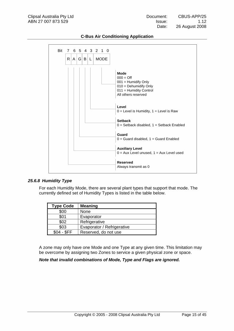
Clipsal Australia Pty Ltd Document: CBUS-APP/25 ABN 27 007 873 529 Issue: Date:
C-Bus Air Conditioning Application
1.12 26 August 2008
MODE
Level0 = Level is Humidity, 1 = Level is Raw
Bit 7 6 5 4 3 2 1 0
Mode000 = Off001 = Humidify Only010 = Dehumidify Only011 = Humidity ControlAll others reserved
R LA G B
Setback0 = Setback disabled, 1 = Setback Enabled
Guard0 = Guard disabled, 1 = Guard Enabled
Auxiliary Level0 = Aux Level unused, 1 = Aux Level used
ReservedAlways transmit as 0
25.6.8 Humidity Type For each Humidity Mode, there are several plant types that support that mode. The currently defined set of Humidity Types is listed in the table below.
Type Code Meaning
$00 None $01 Evaporator $02 Refrigerative $03 Evaporator / Refrigerative
$04 - $FF Reserved, do not use
A zone may only have one Mode and one Type at any given time. This limitation may be overcome by assigning two Zones to service a given physical zone or space.
Note that invalid combinations of Mode, Type and Flags are ignored.
Copyright © 2005 - 2008 Clipsal Australia Pty Ltd Page 15 of 45

Clipsal Australia Pty Ltd Document: CBUS-APP/25 ABN 27 007 873 529 Issue: Date:
C-Bus Air Conditioning Application
1.12 26 August 2008
Copyright © 2005 - 2008 Clipsal Australia Pty Ltd Page 16 of 45
25.6.9 Humidity Errors The following error codes are to be respected for all C-Bus HVAC and thermostat devices. Developers are free to add further codes for specific purposes. Such codes shall have numbers greater than or equal to $80, and should be registered with the C-Bus Enabled coordinator.
Error Code Meaning $00 No Error $01 Humidifier total failure $02 Dehumidifier total failure $03 Fan total failure $04 Humidity Sensor failure $05 Humidifier temporary problem $06 Dehumidifier temporary problem $07 Fan temporary problem $08 Humidifier service required $09 Dehumidifier service required $0A Fan service required $0B Filter replacement required
$0C - $7F Reserved, not to be used $80 - $FF Available for developers
25.6.10 Humidity Status Flags The Humidity Status Flags give information on the Humidity Zone status.
Bit Item Bit = 0 Bit = 1 0 Humidifying Plant: Off On 1 Dehumidifying Plant Off On 2 Fan Active Off On 3 Damper State Closed Open 4 Free - - 5 Busy No Yes 6 Error No Yes 7 Expansion No Yes
Clipsal Australia Pty Ltd Document: CBUS-APP/25 ABN 27 007 873 529 Issue: Date:
C-Bus Air Conditioning Application
1.12 26 August 2008
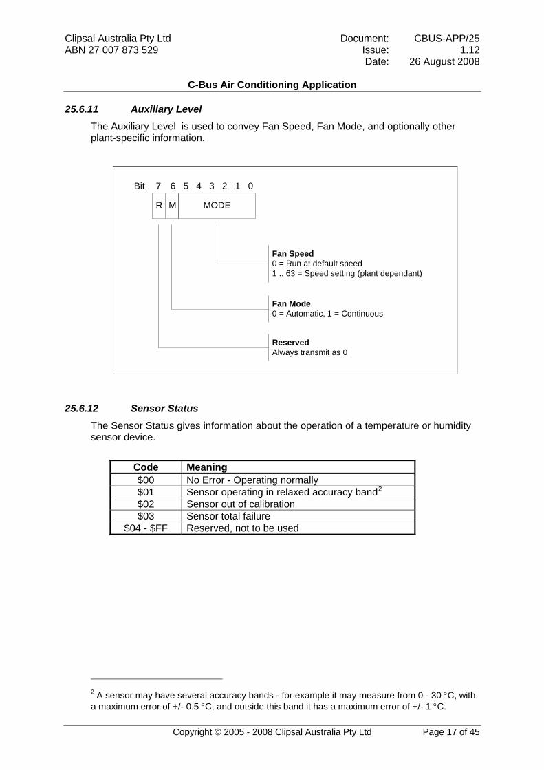
25.6.11 Auxiliary Level The Auxiliary Level is used to convey Fan Speed, Fan Mode, and optionally other plant-specific information.
MODE
Bit 7 6 5 4 3 2 1 0
Fan Speed0 = Run at default speed1 .. 63 = Speed setting (plant dependant)
R M
Fan Mode0 = Automatic, 1 = Continuous
ReservedAlways transmit as 0
25.6.12 Sensor Status The Sensor Status gives information about the operation of a temperature or humidity sensor device.
Code Meaning $00 No Error - Operating normally $01 Sensor operating in relaxed accuracy band2
$02 Sensor out of calibration $03 Sensor total failure
$04 - $FF Reserved, not to be used
2 A sensor may have several accuracy bands - for example it may measure from 0 - 30 °C, with a maximum error of +/- 0.5 °C, and outside this band it has a maximum error of +/- 1 °C.
Copyright © 2005 - 2008 Clipsal Australia Pty Ltd Page 17 of 45
Clipsal Australia Pty Ltd Document: CBUS-APP/25 ABN 27 007 873 529 Issue: Date:
C-Bus Air Conditioning Application
1.12 26 August 2008
Copyright © 2005 - 2008 Clipsal Australia Pty Ltd Page 18 of 45
25.6.13 Zone Identification
25.6.13.1 The Unswitched Zone By convention, Zone 0 is the Unswitched Zone.
The Unswitched Zone exists in all systems and is a zone which can not be switched off when the system is operating. The purpose of this is to ensure that there is always a path for air to return from the outlet to the inlet.
25.6.13.2 Zone Groups and Zone Lists HVAC devices exist within a defined Zone Group. Each Zone Group is both physically and logically separated from all the other Zone Groups on the network.
Within each Zone Group there are several Zones. These Zones may share plant, sensors and control elements.
Commands can be applied to one or more Zones in a Zone Group at any time, using a Zone List. A Zone List is specified as a bit encoded byte and may specify more than one Zone:
Bits 0-6: Zones 0 to 6
Bit 7: Expansion – if set, further zones may be added
Eg. A value of %00001011 = $0B means the Unswitched Zone and Zones 1 and 3 are addressed.
Note: expansion beyond 7 Zones per Zone Group is not supported at this time. Please consult Clipsal Integrated Systems if expansion is required.
25.6.14 Schedule Information The purpose of the schedule is to store information about how a Zone is to be managed at a particular time of day.
Typically schedules are broken down into periods and there may be many periods per day. Simple systems may only define a few periods that are used for all seven days. Complex systems may have different programs for each day of the week, six or more periods per day and different schedules for each zone.
It is therefore important to specify not only the data in the schedule but also the way in which the data is stored.
25.6.14.1 Start Times Start Times for all schedule commands shall be sent as an integer, indicating the number of minutes since 12am Sunday Morning.
Eg Friday 9:15am would be stored as 7755.
A value of 0xFFFF indicates a null entry. A null entry is a period that should be ignored in the Schedule sequence.
25.6.14.2 Set Levels Set levels for all schedules commands shall be sent as per sections 25.5.1 and 25.5.3.

Clipsal Australia Pty Ltd Document: CBUS-APP/25 ABN 27 007 873 529 Issue: Date:
C-Bus Air Conditioning Application
1.12 26 August 2008
Copyright © 2005 - 2008 Clipsal Australia Pty Ltd Page 19 of 45
25.6.14.3 Entry The Entry index for schedule commands shall be sent as an integer representing the location of the period within the schedule. This index is required to allow the Schedule service to determine which record to update with the new data.
25.6.14.4 Schedule Formats The table below lists the currently recognised set of Schedule formats.
Format No. Meaning
1 Four periods per day, all days the same 2 Four periods per day, week / weekend format 3 Four periods per day, each day different 4 Six periods per day, all days the same 5 Six periods per day, week / weekend format 6 Six periods per day, each day different 7 No fixed number of periods
Clipsal Australia Pty Ltd Document: CBUS-APP/25 ABN 27 007 873 529 Issue: Date:
C-Bus Air Conditioning Application
1.12 26 August 2008
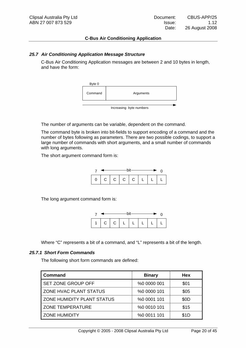
25.7 Air Conditioning Application Message Structure C-Bus Air Conditioning Application messages are between 2 and 10 bytes in length, and have the form:
Byte 0
Increasing byte numbers
Command Arguments
The number of arguments can be variable, dependent on the command.
The command byte is broken into bit-fields to support encoding of a command and the number of bytes following as parameters. There are two possible codings, to support a large number of commands with short arguments, and a small number of commands with long arguments.
The short argument command form is:
0 C C C C L L L
7 0bit
The long argument command form is:
1 C C L L L L L
7 0bit
Where “C” represents a bit of a command, and “L” represents a bit of the length.
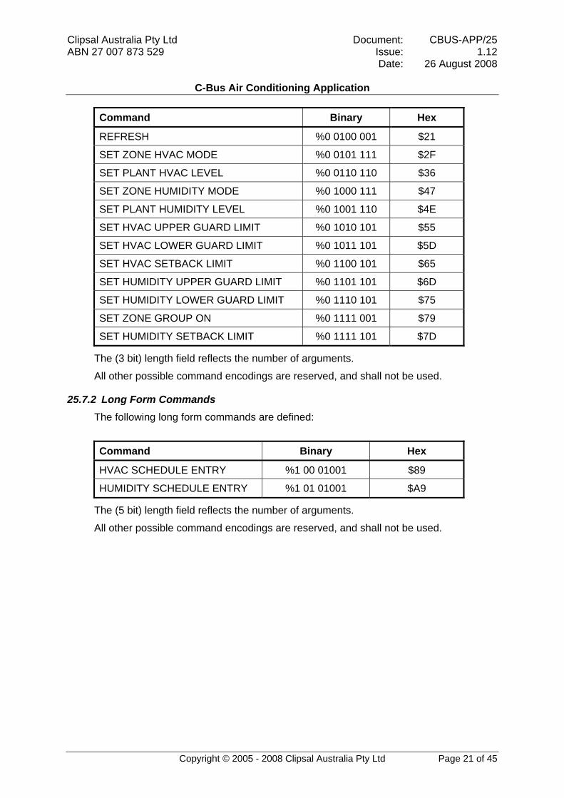
25.7.1 Short Form Commands The following short form commands are defined:
Command Binary Hex
SET ZONE GROUP OFF %0 0000 001 $01
ZONE HVAC PLANT STATUS %0 0000 101 $05
ZONE HUMIDITY PLANT STATUS %0 0001 101 $0D
ZONE TEMPERATURE %0 0010 101 $15
ZONE HUMIDITY %0 0011 101 $1D
Copyright © 2005 - 2008 Clipsal Australia Pty Ltd Page 20 of 45
Clipsal Australia Pty Ltd Document: CBUS-APP/25 ABN 27 007 873 529 Issue: Date:
C-Bus Air Conditioning Application
1.12 26 August 2008
Copyright © 2005 - 2008 Clipsal Australia Pty Ltd Page 21 of 45
Command Binary Hex
REFRESH %0 0100 001 $21
SET ZONE HVAC MODE %0 0101 111 $2F
SET PLANT HVAC LEVEL %0 0110 110 $36
SET ZONE HUMIDITY MODE %0 1000 111 $47
SET PLANT HUMIDITY LEVEL %0 1001 110 $4E
SET HVAC UPPER GUARD LIMIT %0 1010 101 $55
SET HVAC LOWER GUARD LIMIT %0 1011 101 $5D
SET HVAC SETBACK LIMIT %0 1100 101 $65
SET HUMIDITY UPPER GUARD LIMIT %0 1101 101 $6D
SET HUMIDITY LOWER GUARD LIMIT %0 1110 101 $75
SET ZONE GROUP ON %0 1111 001 $79
SET HUMIDITY SETBACK LIMIT %0 1111 101 $7D
The (3 bit) length field reflects the number of arguments.
All other possible command encodings are reserved, and shall not be used.
25.7.2 Long Form Commands The following long form commands are defined:
Command Binary Hex
HVAC SCHEDULE ENTRY %1 00 01001 $89
HUMIDITY SCHEDULE ENTRY %1 01 01001 $A9
The (5 bit) length field reflects the number of arguments.
All other possible command encodings are reserved, and shall not be used.

Clipsal Australia Pty Ltd Document: CBUS-APP/25 ABN 27 007 873 529 Issue: Date:
C-Bus Air Conditioning Application
1.12 26 August 2008
Copyright © 2005 - 2008 Clipsal Australia Pty Ltd Page 22 of 45
25.8 Defined Commands A command is followed by the Network Variable Identification, and then any relevant information to be applied by the command to the Network Variable.
25.8.1 HVAC Schedule Entry Command: $89
Arguments: <Zone Group> <Zone list> <Entry> <Format> <HVAC Mode & Flags> <Start Time> <Set Level>
Meaning: Broadcast message loading a change to a Schedule record, or showing a current Schedule record.
Originator: User Interface (when loading a Schedule Record)
Schedule Service (when showing a current Schedule Record)
Notes: When sent by anything apart from the Schedule Service, this message changes the information contained in the specified schedule record. It is up to the originator of the message to ensure that the change does not corrupt the schedule.
When sent by the Schedule Service, this message shows the information contained in the specified schedule record.
The information in this message describes a schedule entry. Whether or not the entry is active or expired is irrelevant.
<Zone Group> and <Zone List> define the Zones affected. See section 25.6.13 for details on format.
<Format> describes the way the data is stored. If the specified format does not match the receiver’s format, the recipient Schedule service either converts its schedule to the required format or ignores the command if it can not apply the format.
<Entry> is the index of the record in the schedule structure. The index translates to a period based on the format of the schedule.
<HVAC Mode & Flags> the HVAC mode and flags (see section 25.6.3)
<Start Time> two bytes representing the number of minutes since Sunday 12.00am
<Set Level> two bytes defining the raw level or set temperature

Clipsal Australia Pty Ltd Document: CBUS-APP/25 ABN 27 007 873 529 Issue: Date:
C-Bus Air Conditioning Application
1.12 26 August 2008
Copyright © 2005 - 2008 Clipsal Australia Pty Ltd Page 23 of 45
25.8.2 Humidity Schedule Entry Command: $A9
Arguments: <Zone Group> <Zone list> <Entry> <Format> <Humidity Mode & Flags> <Start Time> <Set level >
Meaning: Broadcast message forcing a change to a Schedule record, or showing current Schedule record.
Originator: User Interface (when loading a Schedule Record)
Schedule Service (when showing a current Schedule Record)
Notes: When sent by anything apart from the Schedule Service, this message changes the information contained in the specified schedule record. It is up to the originator of the message to ensure that the change does not corrupt the schedule.
When sent by the Schedule Service, this message shows the information contained in the specified schedule record.
The information in this message describes a schedule entry. Whether or not the entry is active or expired is irrelevant.
<Zone Group> and <Zone List> define the zones affected. See section 25.6.13 for details on format
<Format> describes the way the data is stored If the specified format does not match the receiver’s format, the recipient Schedule service either converts its schedule to the required format or ignores the command if it can not apply the format.
<Entry> is the index of the record in the schedule structure. The index translates to a period based on the format of the schedule.
<Humidity Mode & Flags> the Humidity mode and flags (see section 25.6.7)
<Start Time> two bytes representing the number of minutes since Sunday 12.00am
<Set Level> two bytes defining the raw level or humidity set point
Clipsal Australia Pty Ltd Document: CBUS-APP/25 ABN 27 007 873 529 Issue: Date:
C-Bus Air Conditioning Application
1.12 26 August 2008
Copyright © 2005 - 2008 Clipsal Australia Pty Ltd Page 24 of 45
25.8.3 Refresh Command: $21
Arguments: <Zone Group>
Meaning: The services in control of the specified Zone Group shall issue commands describing its current schedule, operating state, and mode.
Originator: Anywhere
Notes: The services in control of the specified Zone Group shall issue a series of commands onto the bus, to describe its current schedule and operating state (as though the air conditioner had powered up).
To prevent excessive C-Bus network bandwidth being consumed this command shall not be issue more frequently than once per 5 minutes.
25.8.4 Zone HVAC Plant Status Command: $05
Arguments: <Zone Group> <Zone List> <HVAC Type> <HVAC Status> <HVAC Error Code>
Meaning: Provides information on how the Zone is performing
Originator: Plant Controller
Notes: This command is used to present status information on the User Interface and inform of any potential problems on the system.
This command is issued whenever the Status of the system changes, or whenever an error needs to be reported by the plant controller.
<Zone Group> and <Zone List> define the zones affected. See section 25.6.13 for details on format
<HVAC Type> See section 25.6.4 The plant type of the piece of plant reporting its status in the Zone Group.
<HVAC Status> See section 25.6.5
<HVAC Error code> See section 25.6.5
The <HVAC Type> field is especially helpful when separate plant controllers are used in the same Zone Group.

Clipsal Australia Pty Ltd Document: CBUS-APP/25 ABN 27 007 873 529 Issue: Date:
C-Bus Air Conditioning Application
1.12 26 August 2008
Copyright © 2005 - 2008 Clipsal Australia Pty Ltd Page 25 of 45
25.8.5 Zone Humidity Plant Status Command: $0D
Arguments: <Zone Group> <Zone List> <Humidity Type> <Humidity Status> <Humidity Error Code>
Meaning: Provides information on how the Zone is performing
Originator: Plant Controller
Notes: This command is used to present status information on the User Interface and inform of any potential problems on the system.
This command is issued whenever the Status of the system changes, or whenever an error needs to be reported by the plant controller.
<Zone Group> and <Zone List> define the zones affected. See section 25.6.13 for details on format
<Humidity Type> See section 25.6.8. The plant type of the piece of plant reporting its status in the Zone Group.
<Humidity Status> See section 25.6.9
<Humidity Error code> See section 25.6.9
The <Humidity Type> field is especially helpful when separate plant controllers are used in the same Zone Group.

Clipsal Australia Pty Ltd Document: CBUS-APP/25 ABN 27 007 873 529 Issue: Date:
C-Bus Air Conditioning Application
1.12 26 August 2008
Copyright © 2005 - 2008 Clipsal Australia Pty Ltd Page 26 of 45
25.8.6 Zone Temperature Command: $15
Arguments: <Zone Group> <Zone List> <Temperature> <Sensor Status>
Meaning: Broadcast of temperature information by a sensor
Originator: Temperature Sensor
Notes: This is a broadcast message from a Temperature sensor service. The Zone Manager with the corresponding Zone number will set the “Current Temperature” Zone Network variable to the value specified.
<Zone Group> and <Zone List> define the zones affected. See section 25.6.13 for details on format
<Temperature> Two bytes encoding the temperature as described in section 25.5.1
<Sensor Status> is a byte that encodes the sensor status as described in section 25.6.12). When the status is "Sensor total failure" or beyond, the <Temperature> field can be assumed to be meaningless.
The current temperature shall be transmitted into C-Bus under the following conditions:
• Within 1 minute of the temperature sensor device having power applied;
• Whenever the temperature changes by a defined threshold (programmed into the temperature sensor device);
• Every five minutes.

Clipsal Australia Pty Ltd Document: CBUS-APP/25 ABN 27 007 873 529 Issue: Date:
C-Bus Air Conditioning Application
1.12 26 August 2008
Copyright © 2005 - 2008 Clipsal Australia Pty Ltd Page 27 of 45
25.8.7 Zone Humidity Command: $1D
Arguments: <Zone Group> <Zone List> <Humidity> <Sensor Status>
Meaning: Broadcast of humidity information by a sensor
Originator: Humidity Sensor
Notes: This is a broadcast message from a Humidity sensor service. The Zone Manager with the corresponding Zone number will set the “Current Humidity” Zone Network variable to the value specified.
<Zone Group> and <Zone List> define the zones affected. See section 25.6.13 for details on format.
<Humidity> two bytes coding the humidity as described in section 25.5.2
<Sensor Status> is a byte that encodes the sensor status as described in section 25.6.12). When the status is "Sensor total failure" or beyond, the <Temperature> field can be assumed to be meaningless.
The current humidity shall be transmitted into C-Bus under the following conditions:
• Within 1 minute of the humidity sensor having power applied;
• Whenever the humidity changes by a defined threshold (programming into the humidity sensor device);
• Every five minutes.
25.8.8 Set Zone Group Off Command: $01
Arguments: <Zone Group>
Meaning: Switches off all plant in all of the Zones of the specific Zone Group
Originator: User Interface
Any C-Bus device capable of issuing lighting style “OFF” commands
Notes: This is a short cut method of totally switching off all air conditioning control, and is compatible the standard C-Bus (lighting) switches.
<Zone Group> the group to be disabled.
Clipsal Australia Pty Ltd Document: CBUS-APP/25 ABN 27 007 873 529 Issue: Date:
C-Bus Air Conditioning Application
1.12 26 August 2008
Copyright © 2005 - 2008 Clipsal Australia Pty Ltd Page 28 of 45
25.8.9 Set Zone Group On Command: $79
Arguments: <Zone Group>
Meaning: Returns the Zone group to its previous operational state.
Originator: User Interface
Any C-Bus device capable of issuing lighting style “ON” commands
Notes: The system retrieves its previous operating information and reinstates it.
This command is compatible with standard C-Bus (lighting) switches.
<Zone Group> the group to be disabled.
25.8.10 Set Zone HVAC Mode Command: $2F
Arguments: <Zone Group> <Zone List> <HVAC Mode & Flags> <HVAC Type> <Level> <Aux Level >
Meaning: Broadcast of HVAC mode and level required for a Zone or Zones.
Originator: User Interface
Schedule Service
Any C-Bus device
Notes: This is a broadcast message from the User Interface or the Schedule service to indicate that the required HVAC mode and / or level for the Zone(s) has changed. The Zone Manager(s) that are servicing the Zone(s) will set its input accordingly.
<Zone Group> and <Zone List> define the Zones affected. See section 25.6.13 for details on format
<HVAC Mode & Flags> the HVAC mode and flags (see section 25.6.3). Modes are mutually exclusive.
<HVAC Type> the type of the HVAC plant (see section 25.6.4) in the zone group to which the mode should be applied.
<Level> Two bytes coding the temperature or a raw level.
<Aux Level> defines the auxiliary level. Should be 0 if unused.
An interval of at least 10 seconds between Set Zone HVAC Mode commands is recommended to avoid nuisance cycling.
Clipsal Australia Pty Ltd Document: CBUS-APP/25 ABN 27 007 873 529 Issue: Date:
C-Bus Air Conditioning Application
1.12 26 August 2008
Copyright © 2005 - 2008 Clipsal Australia Pty Ltd Page 29 of 45
25.8.11 Set Plant HVAC Level Command: $36
Arguments: <Zone Group> <Zone List> <HVAC Mode & Flags> <HVAC Type> <Level> <Aux Level>
Meaning: Broadcast of demand level required for a Zone.
Originator: Zone Manager
Notes: This is a broadcast message from a Zone Manager service to indicate that the required HVAC level for the Zone has changed.
The Plant Manager that is servicing the Zone will set its output accordingly.
<Zone Group> and <Zone List> define the zones affected. See section 25.6.13 for details on format
<HVAC Mode & Flags> the HVAC mode and flags (see section 25.6.3). Plant demand for Heating or Cooling must use the Heat / Cool mode, with the plant demand set by the <Level> parameter and the sign of the level being important. The separate Heat mode and Cool mode have no meaning for a Plant Controller. The Setback and Guard flags have no meaning for a Plant Controller, and will be ignored.
<HVAC Type> the HVAC type (see section 25.6.4) in the zone group to which the plant HVAC level should be applied.
<Level> is a single signed byte indicating the level of output required for the zone. Valid values are –128 to +127. A level of 0 indicates that the plant should be off. Note that for the Heat / Cool mode, a positive value infers Heating while a negative value infers Cooling.
<Aux Level> is a single byte indicate the level of any auxiliary required for the zone. Valid values are 0-255. If unused the value should be 0.

Clipsal Australia Pty Ltd Document: CBUS-APP/25 ABN 27 007 873 529 Issue: Date:
C-Bus Air Conditioning Application
1.12 26 August 2008
Copyright © 2005 - 2008 Clipsal Australia Pty Ltd Page 30 of 45
25.8.12 Set Zone Humidity Mode Command: $47
Arguments: <Zone Group> <Zone List> <Humidity Mode & Flags> <Humidity Type> <Level> <Aux Level>
Meaning: Broadcast of Humidity mode required for a Zone.
Originator: User Interface
Schedule Service
Any C-Bus device
Notes: This is a broadcast message from the User Interface or the Schedule service to indicate that the required Humidity mode for the Zone has changed. The Zone Manager that is servicing the Zone will set its input accordingly.
<Zone Group> and <Zone List> define the zones affected. See section 25.6.13 for details on format
<Humidity Mode & Flags> the Humidity mode and flags (see section 25.6.7). Modes are mutually exclusive.
<Humidity Type> the type of Humidity plant (see section 25.6.7) in the zone group to which the level should be applied
<Level> The level may be a humidity or a raw level (2 bytes).
<Aux Level> defines the auxiliary level. Should be 0 if unused.
An interval of at least 10 seconds between Set Zone Humidity Mode commands is recommended to avoid nuisance cycling.

Clipsal Australia Pty Ltd Document: CBUS-APP/25 ABN 27 007 873 529 Issue: Date:
C-Bus Air Conditioning Application
1.12 26 August 2008
Copyright © 2005 - 2008 Clipsal Australia Pty Ltd Page 31 of 45
25.8.13 Set Plant Humidity Level Command: $4E
Arguments: <Zone Group> <Zone List> <Humidity Mode & Flags> <Humidity Type> <Level> <Aux Level>
Meaning: Broadcast of humidity demand required for a Zone.
Originator: Zone Manager
Notes: This is a broadcast message from a Zone Manager service to indicate that the required Humidity level for the Zone has changed. The Plant Manager that is servicing the zone will set its output accordingly.
<Zone Group> and <Zone List> define the Zones affected. See section 25.6.13 for details on format
<Humidity Mode & Flags> the Humidity mode and flags (see section 25.6.7). Modes are mutually exclusive. The Setback and Guard flags have no meaning for a Plant Controller, and will be ignored.
<Humidity Type> the Humidity type (see section 25.6.7) in the zone group to which the plant humidity level should be applied
<Level> is a single byte indicating the level of output required for the Zone. Valid values are 0-255. A level of 0 indicates that the plant should be off.
<Aux Level> is a single byte indicate the level of any auxiliary required for the zone. Valid values are 0-255. If unused the value should be 0.
25.8.14 Set HVAC Upper Guard Limit Command: $55
Arguments: <Zone Group> <Zone List> <Limit> <HVAC Mode & Flags>
Meaning: Sets the absolute maximum temperature allowed in the Zone.
Originator: User Interface
Notes: The Zone Manager will attempt to keep the temperature in the Zone below this level even if the Zone is off. This value is only used if the Guard function is enabled.
<Zone Group> and <Zone List> define the zones affected. See section 25.6.13 for details on format
<Limit> Two bytes encoding the temperature limit (see section 25.5.1).
<HVAC Mode & Flags> determines ONLY how the Temperature limit is to be interpreted
Clipsal Australia Pty Ltd Document: CBUS-APP/25 ABN 27 007 873 529 Issue: Date:
C-Bus Air Conditioning Application
1.12 26 August 2008
Copyright © 2005 - 2008 Clipsal Australia Pty Ltd Page 32 of 45
25.8.15 Set HVAC Lower Guard Limit Command: $5D
Arguments: <Zone Group> <Zone List> <Limit> <HVAC Mode & Flags>
Meaning: Sets the absolute minimum temperature allowed in the Zone.
Originator: User Interface
Notes: The Zone Manager will attempt to keep the temperature in the Zone above this level even if the Zone is off. This value is only used if the Guard function is enabled.
<Zone Group> and <Zone List> define the zones affected. See section 25.6.13 for details on format
<Limit> Two bytes encoding the temperature limit (see section 25.5.1).
<HVAC Mode & Flags> determines ONLY how the Temperature limit is to be interpreted
25.8.16 Set HVAC Setback Limit Command: $65
Arguments: <Zone Group> <Zone List> <Limit> <HVAC Mode & Flags>
Meaning: Sets the error allowed in the set temperature for the Zone.
Originator: User Interface
Notes: The Zone Manager will attempt to keep the temperature in the Zone within <limit> of the set point. This value is only used if the setback function is enabled.
<Zone Group> and <Zone List> define the zones affected. See section 25.6.13 for details on format
<Limit> Two bytes encoding the temperature limit (see section 25.5.1).
<HVAC Mode & Flags> determines ONLY how the Temperature limit is to be interpreted

Clipsal Australia Pty Ltd Document: CBUS-APP/25 ABN 27 007 873 529 Issue: Date:
C-Bus Air Conditioning Application
1.12 26 August 2008
Copyright © 2005 - 2008 Clipsal Australia Pty Ltd Page 33 of 45
25.8.17 Set Humidity Upper Guard Limit Command: $6D
Arguments: <Zone Group> <Zone List> <Limit> <Humidity Mode & Flags>
Meaning: Sets the absolute maximum humidity allowed in the Zone.
Originator: User Interface
Notes: The Zone Manager will attempt to keep the humidity in the Zone below this level even if the Zone is off. This value is only used if the Guard function is enabled.
<Zone Group> and <Zone List> define the zones affected. See section 25.6.13 for details on format
<Limit> Two bytes defining the humidity limit (see section 25.5.2).
<Humidity Mode & Flags> determines ONLY how the humidity limit is to be interpreted
25.8.18 Set Humidity Lower Guard Limit Command: $75
Arguments: <Zone Group> <Zone List> <Limit> <Humidity Mode & Flags>
Meaning: Sets the absolute minimum humidity allowed in the Zone.
Originator: User Interface
Notes: The Zone Manager will attempt to keep the humidity in the Zone above this level even if the Zone is off. This value is only used if the Guard function is enabled.
<Zone Group> and <Zone List> define the zones affected. See section 25.6.13 for details on format
<Limit> Two bytes defining the humidity limit (see section 25.5.2).
<Humidity Mode & Flags> determines ONLY how the humidity limit is to be interpreted

Clipsal Australia Pty Ltd Document: CBUS-APP/25 ABN 27 007 873 529 Issue: Date:
C-Bus Air Conditioning Application
1.12 26 August 2008
Copyright © 2005 - 2008 Clipsal Australia Pty Ltd Page 34 of 45
25.8.19 Set Humidity Setback Limit Command: $7D
Arguments: <Zone Group> <Zone List> <Limit> <Humidity Mode & Flags>
Meaning: Sets the error allowed in the set humidity for the Zone.
Originator: User Interface
Notes: The Zone Manager will attempt to keep the humidity in the Zone within <limit> of the set point. This value is only used if the setback function is enabled.
<Zone Group> and <Zone List> define the zones affected. See section 25.6.13 for details on format
<Limit> Two bytes defining the humidity limit (see section 25.5.2).
<Humidity Mode & Flags> determines ONLY how the humidity limit is to be interpreted
25.9 Message Priority Air Conditioner Application messages shall always be transmitted at the lowest priority (Class 4), unless otherwise noted.
Thus, to send a Class 4 message, use a message header of (for example) $05.
25.10 Internetwork Routing Air Conditioner Application messages may be routed via one or more C-Bus bridges or gateway devices. Such messages will be received with a message type indicating point-multipoint, but will have a non-zero Network routing.
Air Conditioner devices that receive such messages shall process them normally.
25.11 Status Reporting Air conditioner devices that respond to C-Bus Air Conditioner Application messages shall not respond to C-Bus status request (MMI) messages.

Clipsal Australia Pty Ltd Document: CBUS-APP/25 ABN 27 007 873 529 Issue: Date:
C-Bus Air Conditioning Application
1.12 26 August 2008
Copyright © 2005 - 2008 Clipsal Australia Pty Ltd Page 35 of 45
25.12 Application & Device Behaviour
25.12.1 Concatenated Commands An Air Conditioning Application device may receive a message containing more bytes than a single command. This permits a single C-Bus transmission to contain multiple commands for a single application.
Devices using C-Bus Air Conditioning Application messages must process all received bytes. This is achieved by placing the received bytes in a buffer, and using the following simple algorithm:
WHILE the buffer contains bytes LOOP
The first byte defines the command type and argument count (refer section 0).
Process the first (command) byte and its arguments
Once processed, remove the command and argument bytes from the buffer
END LOOP
Air Conditioning Application devices are not required to generate Concatenated Commands.
25.12.2 State Air conditioner devices are expected to maintain some state information internally, including across power failures.
25.12.3 Power on (after power failure) A device implementing this Air-conditioning application shall, when power is restored, transmit information onto C-Bus describing the network variables.
The information to be transmitted is the same information transmitted in response to a received Refresh command.
To avoid C-Bus network congestion, there should be a delay of between about 20 and 60 seconds after restoration of power before the information is transmitted.
25.12.4 The “Fan Coil” Plant Type C-Bus ToolKit supports an additional type of “Fan Coil”. Although this is a quite distinct type of plant, it is functionally similar to hydronic plant, and uses the hydronic plant type in the C-Bus messaging.
25.12.5 Mode The concept of a “mode” does not exist within the C-Bus protocol, but it does exist in the equipment which communicates using the protocol. There are four possible modes of operation:
• Manual
• Program (schedule control)
• Override (temporary schedule override)

Clipsal Australia Pty Ltd Document: CBUS-APP/25 ABN 27 007 873 529 Issue: Date:
C-Bus Air Conditioning Application
1.12 26 August 2008
Copyright © 2005 - 2008 Clipsal Australia Pty Ltd Page 36 of 45
• Auto (only applicable to evaporative plant)
Transition between the modes is communicated via C-Bus using three enable application groups (discussed below).
In addition, if using evaporative plant to cool, the HVAC Mode “Raw Level” flag is used to indicate that “manual” mode is running (rather than “auto” mode).
25.12.6 Set-Level The set-level (or set-point) for the HVAC system is normally the temperature which is desired for the zone.
Depending on the Operating Type, the Plant Type and the Mode, the Set-Level could also be a Comfort Level (cooling, evaporative plant) or a fan speed (vent only).
25.12.7 Comfort Level When using evaporative plant, it difficult to maintain a specific temperature (set-level). Instead, the industry practice is to present the user with a Comfort Level. These are internally mapped to a temperature as follows:
Temperature = (Comfort Level – 1) x TStep + TStart
Where
TStep = step between comfort levels (0.5°C by default)
TStart = temperature of first comfort level (16°C by default)
There are a limited number of comfort levels (20 by default).
Assuming the use of the default values, the comfort levels 1 to 20 map to temperatures of 16°C to 25.5°C.
25.12.8 Fan Speed The fan speed is limited to the number of speeds available in the plant. It is possible that the heating and cooling plant have different numbers of fan speeds available.
There is a fan speed option of “auto”. Despite the name, it is not some sort of automatic control, but actually corresponds to a pre-selected fan speed.
25.12.9 To Monitor an HVAC System When HVAC C-Bus Messages are received, the data from them needs to be extracted into the internal model. Messages not listed below can be ignored.
Zone HVAC Plant Status Message The following data should be extracted from this message:
• Plant Type
• HVAC Status (cooling, heating etc)
• Error Number

Clipsal Australia Pty Ltd Document: CBUS-APP/25 ABN 27 007 873 529 Issue: Date:
C-Bus Air Conditioning Application
1.12 26 August 2008
Copyright © 2005 - 2008 Clipsal Australia Pty Ltd Page 37 of 45
Zone Temperature Message The Zone Temperature can be extracted from this message.
Set Zone Group Off Message The Operating type of the zones in the zone group can be set to Off when this message is received.
Set Zone Group On Message The Operating type of the zones in the zone group can not be changed when this message is received because it is unknown what the new Operating Type will be.
Set HVAC Zone Mode Message The following data should be extracted from this message:
• Mode
• Aux level
• Raw level (if the Raw Level flag is set)
• Set-level temperature (if Raw Level flag is not set)
This message can also be used to select between the Manual and Auto modes of operation (see below).
If the plant has evaporative plant running (ie cooling), then the Raw Level flag indicates that the Manual mode is being used, otherwise the Auto mode is being used. This should not affect Program or Override modes.
Set Plant HVAC Level Message The Set Plant HVAC Level message is primarily of interest to the C-Bus Thermostat and any Plant control equipment. The only time this is required by a monitoring device is to see if a zone Operating Type has changed to off.
Enable Group Change Three Schedule Enable Application Groups associated with HVAC are used to communicate the transition between the Modes:
• Schedule Enable Group: when a C-Bus message for this group is seen on C-Bus, the zones corresponding to the set bits in the “value” of the message are set to “program” mode. This enables schedule control of the selected zones.
• Schedule Disable Group: when a C-Bus message for this group is seen on C-Bus, the zones corresponding to the set bits in the “value” of the message are set to “manual” mode. This disables schedule control of the selected zones. If it is changing from Program or Override mode and there is evaporative plant and the operating type is cool then change the mode to “auto”, rather than “manual”.

Clipsal Australia Pty Ltd Document: CBUS-APP/25 ABN 27 007 873 529 Issue: Date:
C-Bus Air Conditioning Application
1.12 26 August 2008
Copyright © 2005 - 2008 Clipsal Australia Pty Ltd Page 38 of 45
• Schedule Override Group: when a C-Bus message for this group is seen on C-Bus, the zones corresponding to the set bits in the “value” of the message are set to “override” mode. This temporarily overrides schedule control of the selected zones to allow for manual control.
Note that you cannot determine the current mode by looking at the current values of the above group addresses. The group addresses trigger a change of Mode, rather than indicating the current Mode.
The bits in the Enable Group “value” are used as follows:
Bit Usage
0 Unswitched Zone
1 Zone 1
2 Zone 2
3 Zone 3
4 Zone 4
5 Unused
6 Unused
7 Unused
So, for example, an Enable Application message received with a Group Address matching the Schedule Enable Group and a value of 7 would mean that the unswitched zone, zone 1 and zone 2 have all gone into “program” mode.
25.12.10 Controlling an HVAC System To control the C-Bus Thermostat, various messages are used. Messages not listed below are not required.
Refresh The use of this message is as described in the protocol.
Set Zone Group On/Off Message The use of these messages is for switching the C-Bus Thermostat on and off. There is no complexity in these messages.
Set HVAC Zone Mode Message When sending to multiple zones:
• If switching off, send to all zones
• If all zones are already off, send to all zones
• Otherwise, only send to Active zones

Clipsal Australia Pty Ltd Document: CBUS-APP/25 ABN 27 007 873 529 Issue: Date:
C-Bus Air Conditioning Application
1.12 26 August 2008
Copyright © 2005 - 2008 Clipsal Australia Pty Ltd Page 39 of 45
If the “vent/fan” operating type is selected OR the plant is evaporative and cooling and in manual mode, then use the raw level.
The Set HVAC Zone Mode message should only be addressed to the active zones. The only time this message should be sent to inactive zones is when changing the Operating Type.
Enable Group Change When changing mode between “Manual”, “Program” and “Override”, it is necessary to send the appropriate Enable Application messages. The Enable Group value should have bits set for each zone which is changing mode.
• Change to “Manual”: send the “Schedule Disable” Group
• Change to “Program”: send the “Schedule Enable” Group
• Change to “Override”: send the “Schedule Override” Group
25.12.11 Making a Thermostat Mimic Panel / Controller General The goal is to be able to replicate the functionality of the C-Bus Thermostat on a separate C-Bus device, such as a Touch Screen.
Although all communication occurs by C-Bus messages, the C-Bus protocol documents do not contain details of the internal operation of the C-Bus Thermostat. This information is necessary in order to be able to emulate its operation.
It will be necessary for the mimic device to contain an internal model to store the HVAC Data.
Zone Group Data For each Zone Group, the following data will be required as a minimum:
• Comfort level data (see below)
o Comfort Level Start
o Comfort Level Step
o Comfort Level Count
• Fan Speeds
o For Heating
o For Cooling
o Is heating or cooling used for fan/vent Operating Type
• Allowed Operating Types
o Off
o Heat
o Cool

Clipsal Australia Pty Ltd Document: CBUS-APP/25 ABN 27 007 873 529 Issue: Date:
C-Bus Air Conditioning Application
1.12 26 August 2008
Copyright © 2005 - 2008 Clipsal Australia Pty Ltd Page 40 of 45
o Heat & cool
o Vent/fan
• Enabled Groups (used for Mode control)
o Schedule Enable Group
o Schedule Disable Group
o Schedule Override Group
• Schedule Control
o Allowed for Evaporative plant ?
o Allowed for non-Evaporative plant ?
• Temperature limits
o Minimum
o Maximum
The above data is required in order to be able to emulate the operation of the C-Bus Thermostat. This data is not available via C-Bus messages, so must be added via some manual process.
Zone Data For each zone within each zone group, the following data will be required as a minimum:
• HVAC Mode & Flags (from the Set Zone HVAC Mode message)
o Mode (Off, heat, cool, heat & cool, vent/fan)
o Raw Level
o Setback Enabled
o Guard Enabled
o Aux Level used
• Set-Level (temperature, comfort level or fan speed)
o One for each Operating Type (see explanation below)
• Raw Level
• Plant type
• Aux level
o Fan mode
o Fan speed
• HVAC Status (from the Zone HVAC Plant Status message)
o Cooling plant on/off
o Heating plant on/off
o Fan on/off

Clipsal Australia Pty Ltd Document: CBUS-APP/25 ABN 27 007 873 529 Issue: Date:
C-Bus Air Conditioning Application
1.12 26 August 2008
Copyright © 2005 - 2008 Clipsal Australia Pty Ltd Page 41 of 45
o Damper open/closed
o Plant busy/not busy
o Error/no error
• Sensor Status
• Error Number
• Mode (manual, program, override, auto)
• Zone enabled
Changing Data It important that the mimic device does not attempt to send C-Bus messages to change any operational parameter until it has received all relevant data. For example, it is not possible to set a new Set Point (which could be a temperature, comfort level or fan speed) until the operating type is known.
Refresh As soon as practical after start-up, the mimic device should send a Refresh command so that all necessary data is available.
Controlling Multiple Zones Generally the mimic device will control multiple Zones within a Zone Group. The C-Bus protocol supports the sending of messages related to multiple zones.
Things get more complex when displaying data from multiple zones. If a parameter is to be displayed (or used) and it relates to multiple zones it is simple if all zones have the same value for that parameter. If they are different, it is necessary to decide which value of the parameter to display (or use).
Depending of the parameter, one of the following is used:
• Default Serviced Zone – the first of the zones which is being serviced. If there are no serviced zones, then use the default Active Zone
• Default Active Zone – the first of the zones which is active
• Default Zone – the first of the zones
Details for each parameter are in the following sections.
Operating Type Only Operating Types which are available for a Zone are able to be set.
Certain Operating Types should not be used with particular Plant Types. For example, a Furnace HVAC system can not be used for cooling. A Furnace/Evaporative Plant can be used for both heating and cooling, but should not be used for the Heat/Cool mode.

Clipsal Australia Pty Ltd Document: CBUS-APP/25 ABN 27 007 873 529 Issue: Date:
C-Bus Air Conditioning Application
1.12 26 August 2008
Copyright © 2005 - 2008 Clipsal Australia Pty Ltd Page 42 of 45
The rules are enforced in the C-Bus ToolKit and the available options need to be stored in the mimic device (see Zone Group Data).
If an attempt is made to set an invalid Operating Type, that value should be skipped or ignored.
The default mode for evaporative cooling is “auto”. If changing to an Operating Type of “cool” and there is evaporative cooling plant and the mode is “manual”, then the mode needs to be changed to “auto”. The “auto” mode is only supported by evaporative cooling plant, so if the Operating Type is changed from “cool” and the mode is “auto”, then the mode should be changed to “manual”.
When displaying the Operating Type for a group of zones, choose the Default Serviced Zone.
The Operating Type is set and received with the Set Zone HVAC Mode message.
Set Point The Set Point is normally the desired temperature but can also be a comfort level or a fan speed. This is the value normally controlled by the knob on the C-Bus Thermostat.
A different Set Point needs to be stored for each Operating Type. This allows for different Set Points for cooling and heating for example. These should be stored in non-volatile memory and recalled when the Operating Type is changed.
The type of Set Point to use is determined as follows:
• Use Fan Speed: if the Operating Type is Vent/Fan OR the plant has evaporative plant, is cooling and the mode is “manual”;
• Use Comfort Level: if the plant has evaporative plant, is cooling and the mode is “auto”; or
• Use Temperature: all other cases
When displaying or controlling the Set Point, the value depends on the type and is calculated as follows:
• For Temperature: the Set Point for the current operating type;
• For a Comfort Level: converted from the temperature Set Point; or
• For Fan Speed: calculated from the Raw Level or the Aux Level (see below)
The Set Point is set and received with the Set Zone HVAC Mode message.
When displaying the Set Point for a group of zones, choose the Default Serviced Zone.
Timeout on Adjustment When a user is adjusting the Set Point, do not send a stream of C-Bus messages for each increment or decrement.
A C-Bus Thermostat will “echo” each change which can cause race conditions. Instead, wait until a few seconds after the user has finished making changes, then send a single Set Zone HVAC Mode message.
Clipsal Australia Pty Ltd Document: CBUS-APP/25 ABN 27 007 873 529 Issue: Date:
C-Bus Air Conditioning Application
1.12 26 August 2008
Copyright © 2005 - 2008 Clipsal Australia Pty Ltd Page 43 of 45
Mode Under some circumstances, certain modes are not allowed:
• If scheduling is disabled for the plant currently being used (evaporative or non-evaporative), then “program” and “override” modes are not allowed;
• Only when cooling with evaporative plant is “auto” mode is allowed;
• For evaporative plants when cooling, transition between “Manual” and “Program”/”Override” (and vice versa) is not allowed;
• When in fan (vent) operating type, only “manual” mode is allowed.
If an attempt is made to set an invalid Mode, that value should be skipped or ignored.
If in “Program” mode and the user attempts to change a parameter such as the Set Point, it is necessary to put the system into “override” mode first.
Mode changes between “Manual”, “Program” and “Override” are communicated with the Enable Groups. Mode changes between “Manual” and “Auto” (for evaporative plant only) are communicated with the Raw Level flag in the Set HVAC Zone Mode message.
When displaying the Mode for a group of Zones, choose the Default Serviced Zone. If there is no serviced or active Zone, use the default Zone.
Plant Status Various flags are available to indicate the status of the plant operation. These can not be controlled by a mimic device but they can be monitored. They are received in the Zone HVAC Plant Status message. These are:
• Cooling plant on/off
• Heating plant on/off
• Fan on/off
• Damper open/closed
• Plant busy/not busy
• Error/no error
When displaying the status for a group of zones, choose the Default Serviced Zone.
For the damper status:
• When displaying the status for a group of zones (usually undesirable), choose the Default Zone.
• The unswitched zone has no damper, so it should always be regarded as being open.
When reporting the error state for a group of zones, it is advisable to report if there is an error in any of them.
Enabling Zones A zone is regarded as being “enabled” if its Operating Type is not “off”.

Clipsal Australia Pty Ltd Document: CBUS-APP/25 ABN 27 007 873 529 Issue: Date:
C-Bus Air Conditioning Application
1.12 26 August 2008
Copyright © 2005 - 2008 Clipsal Australia Pty Ltd Page 44 of 45
When displaying the state for a group of zones (usually undesirable), choose the Default Active Zone.
Note that the Unswitched zone should be regarded as always being enabled.
Since there is no intrinsic concept of a zone “state” (on/off), controlling the zone state is done through the Operating Type. Switching a zone off is simply a matter of setting its operating type to “off”. If switching a zone on, the process is a little more complex:
1. Iterate through the other zones in the zone group to find one which is on.
2. Use that Operating Type and Set-Level for the zone which is being switched on
3. Send a Set Zone HVAC Mode message for this and any other zones being switched on.
Fan Speed The fan speed is communicated (and stored) in two different ways, depending on the circumstances.
• If evaporating plant is running (cooling) and the mode is not “manual” then the fan is regarded as being “auto”;
• Otherwise, if the evaporative plant is running or the Operating Type is “vent/fan”, then the fan speed is in the “Raw Level”;
• Otherwise, the fan speed is in the “Aux Level”.
If the fan speed is in the Raw Level:
Fan Speed = Raw Level / $7FFF * Number of Fan Speeds
If the fan speed is in the Aux Level:
If “Automatic” bit is not set then
Fan Speed = Aux Level / $3F * Number of Fan Speeds
Note that the number of fan speeds may be different for heating and cooling.
When displaying the fan speed for a group of zones, choose the Default Active Zone.
When a user is adjusting the fan speed, do not send a stream of C-Bus messages for each increment or decrement. The C-Bus Thermostat will “echo” each change which can cause race conditions. Instead, wait until a few seconds after the user has finished making changes, then send a single Set Zone HVAC Mode message.
Setback Control Setback does not apply when the set-level is controlling the fan speed. When using the fan, setback should be regarded as being off. The circumstances under which this applies are :
• Operating Type is “Fan/Vent”
• The plant has evaporative plant, is cooling and the mode is “manual”

Clipsal Australia Pty Ltd Document: CBUS-APP/25 ABN 27 007 873 529 Issue: Date:
C-Bus Air Conditioning Application
1.12 26 August 2008
Copyright © 2005 - 2008 Clipsal Australia Pty Ltd Page 45 of 45
When displaying the setback state for a group of zones, choose the Default Serviced Zone.
Zone Group State (Power) The best way to determine if the Thermostat is on (i.e. the Zone Group is on) is to iterate through the zones in the zone group to see if any are on.
The state can be controlled using the Set Zone Group On/Off commands. The Thermostat will respond by issuing a Set Zone HVAC Mode command with the new state of the zones.
Sensor Status When reporting the status of the temperature sensors for multiple zones, it is best to iterate through the zones and show the worst case (highest value) error condition.