air balancing application guide - titus hvac · application guide air balancing table of contents...
TRANSCRIPT

APPLICATION GUIDE
Redefine your comfort zone. ™ | www.titus-hvac.com
Air Balancing

2 Application Guide - AIR BALANCING Redefine your comfort zone. ™ | www.titus-hvac.com
APPLICATION GUIDEAIR BALANCING
Table of Contents
This document provides general information necessary to balance Titus HVAC equipment. Use this document along with the specific product flow factors to balance air distribution equipment.
Additional information may be found at the Titus website, its address is www.titus-hvac.com.
Titus, the Titus Spiral, and are trademarks of Titus. All other trademarks, noted or not, are the property of their respective owners.
Foreword. ..................................................................................................................................................................3
Introduction...............................................................................................................................................................3
Methodology .............................................................................................................................................................4 Flow and Pressure Requirements........................................................................................................................4 Example – Air Volume ....................................................................................................................................4 Example – Air Pressure ..................................................................................................................................4 Example – Fan Total Pressure.........................................................................................................................4 Example – Fan Volume ...................................................................................................................................4
Definitions .................................................................................................................................................................5 Anemometer ........................................................................................................................................................5 Area Factor ...........................................................................................................................................................5 Velocity .................................................................................................................................................................5 Velometer .............................................................................................................................................................5
Instrumentation ........................................................................................................................................................6
Preliminary Balancing Steps .....................................................................................................................................6
Proportional Balancing Steps ...................................................................................................................................7
Grille Free Area .........................................................................................................................................................4
Cross Reference ........................................................................................................................................................5
System Balancing Worksheet ..................................................................................................................................6

3Application Guide - AIR BALANCINGRedefine your comfort zone. ™ | www.titus-hvac.com
Foreword
Introduction
The intention of an air conditioning engineer is to design an air distribution system to deliver the required air volume to satisfy the space load. The duct system components are sized to deliver air without excessive balancing. Under ideal conditions, the pressure loss from the fan to the supply outlets should be sufficient to overcome the pressure loss through the supply outlet and distribute the air to the space. This ideal system would require no further airflow adjustments. However, in reality this condition is usually not met. Therefore, the system and component balancing is required to achieve the engineer’s design criteria.
When fans operate at a constant speed they have such characteristics that for a given air flow rate a certain pressure will be developed at the fan discharge. If the pressure requirement changes, the quantity of air delivered will also change. It is important to note that each downstream damper adjustment affects the fan pressure and airflow. An individual outlet cannot be adjusted without affecting the rest of the system. Therefore the system must be balanced in accordance with some systematic procedure. The objective of the manual is to provide a basic understanding of air conditioning system balancing. The balancing method presented within this manual uses a velometer positioned by hand at each grille. The method is generally referred to as the “Chicago Proportional Balancing” method.
4 Application Guide - AIR BALANCING Redefine your comfort zone. ™ | www.titus-hvac.com
APPLICATION GUIDEAIR BALANCING
Methodology
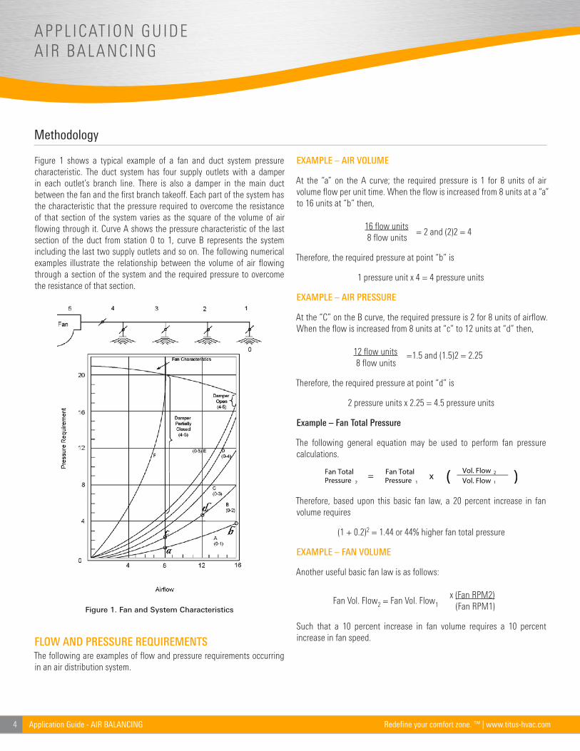
Figure 1 shows a typical example of a fan and duct system pressure characteristic. The duct system has four supply outlets with a damper in each outlet’s branch line. There is also a damper in the main duct between the fan and the first branch takeoff. Each part of the system has the characteristic that the pressure required to overcome the resistance of that section of the system varies as the square of the volume of air flowing through it. Curve A shows the pressure characteristic of the last section of the duct from station 0 to 1, curve B represents the system including the last two supply outlets and so on. The following numerical examples illustrate the relationship between the volume of air flowing through a section of the system and the required pressure to overcome the resistance of that section.
FLOW AND PRESSURE REQUIREMENTSThe following are examples of flow and pressure requirements occurring in an air distribution system.
EXAMPLE – AIR VOLUME
At the “a” on the A curve; the required pressure is 1 for 8 units of air volume flow per unit time. When the flow is increased from 8 units at a “a” to 16 units at “b” then,
16 flow units 8 flow units
= 2 and (2)2 = 4
Therefore, the required pressure at point “b” is
1 pressure unit x 4 = 4 pressure units
EXAMPLE – AIR PRESSURE
At the “C” on the B curve, the required pressure is 2 for 8 units of airflow. When the flow is increased from 8 units at “c” to 12 units at “d” then,
12 flow units 8 flow units
=1.5 and (1.5)2 = 2.25
Therefore, the required pressure at point “d” is
2 pressure units x 2.25 = 4.5 pressure units
Example – Fan Total Pressure
The following general equation may be used to perform fan pressure calculations.
Therefore, based upon this basic fan law, a 20 percent increase in fan volume requires
(1 + 0.2)2 = 1.44 or 44% higher fan total pressure
EXAMPLE – FAN VOLUME
Another useful basic fan law is as follows:
Fan Vol. Flow2 = Fan Vol. Flow1x (Fan RPM2) (Fan RPM1)
Such that a 10 percent increase in fan volume requires a 10 percent increase in fan speed.
Figure 1. Fan and System Characteristics
5Application Guide - AIR BALANCINGRedefine your comfort zone. ™ | www.titus-hvac.com
Definitions
Anemometer
Instrument used for determining the force or speed of air. Two anemometer types are as follows:
• Vane: Used to measure sidewalls, grilles, registers, and ceiling diffusers. The vane anemometers are commonly depicted with balancing Titus air system equipment.
• Rotating vane: Used to measure linear feet of air passing through it. Generally used for measuring air velocity through supply, return and exhaust air grilles, registers, or openings. Do not use a rotating vane anemometer as an averaging instrument.
Area Factor
The area factor, AK, is the effective area of the outlet at the point of outlet velocity, the VK measurement is such that the volume flow is equal to AK times VK.
The area factors are based on equalized airflow 12 flow units in the outlet neck.
Note: Severe damper throttling or takeoffs without air turning devices or control grids can affect the indicated airflow accuracy of these factors dramatically.
Velocity
The measurement of air speed as it exits the grille, register, or diffuser. Velocity is averaged by number of readings taken at grille, register, or diffuser. Velocity is measured with instruments and depending on application, the velocity being measured can be either supply or return air.
Velometer
Instrument used for HVAC balancing, static pressure measurements, energy audits.
6 Application Guide - AIR BALANCING Redefine your comfort zone. ™ | www.titus-hvac.com
APPLICATION GUIDEAIR BALANCING
Instrumentation
Preliminary Balancing Steps
We recommend all system balancing instruments calibrated annually with the manufacturer’s furnished calibration curve. Also, it is strongly recommended these instruments be used within their specified accuracy range. The appropriate usage and accurate instrument calibration ensures ongoing credibility and accuracy for the air balancing technician.
For return grille balancing, the position of the velometer probe must be as shown in the diagrams for each diffuser shown. Based on the vane anemometer use, the attachment of the tubing to the anemometer requires a reversing movement on the instrument. Alternative methods may use a flow hood in a similar manner. Consult organizations such as NEBB and AADC for more information on those methods that use the flow hood to measure volume flow directly.
Use the following information to balancing preparation.
1. Open all system air valves and dampers in both supply and return ducts.
2. Set all other dampers to normal operating position.
3. Check all filters and coils to ensure they are clear of dirt and debris.
4. Start all fans.
5. Check rotation of all fans and ensure the direction is correct.
6. Copy the balancing worksheet provided in this manual to record readings.
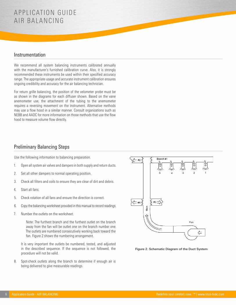
7. Number the outlets on the worksheet.
Note: The furthest branch and the furthest outlet on the branch away from the fan will be outlet one on the branch number one. The outlets are numbered consecutively working back toward the fan. Figure 2 shows the numbering arrangement.
It is very important the outlets be numbered, tested, and adjusted in the described sequence. If the sequence is not followed, the procedure will not be valid.
8. Spot-check outlets along the branch to determine if enough air is being delivered to give measurable readings.
Figure 2. Schematic Diagram of the Duct System

7Application Guide - AIR BALANCINGRedefine your comfort zone. ™ | www.titus-hvac.com
Proportional Balancing Steps
The following balancing information is specific to low pressure ventilating and air conditioning systems.
1. Measure velocities at Outlet 1, the furthest outlet on the branch.
2. Determine the average velocity and use the System Balancing Worksheet to record the value in the column VM (measured velocity) under Adjustments I heading. This indicates the first reading of that outlet.
3. Determine the ratio of VD (measure to design velocity) and record R (ratio) under Adjustment I and 1B. Use the following equation to determine ratios.
R = Measured Velocity VM
AK (flow factor)= VD
4. Proceed to the second outlet. Determine the average velocity (VM) and ratio (R) and record these values under Adjustment I and 2A.
5. Compare R values from 1B and 2A under Adjustment I. If the R values are not equal, adjust Outlet 2 so R2 will approach R1. Do not adjust Outlet 1.
6. After adjustment, record VM and R values for Outlet 2 under II and 2A.
7. Go back to Outlet 1 and measure VM. Record VM and R values under Adjustment II, 1B. If R values shown under adjustment II, 1B and 2A vary more than 0.1, they are not proportionally balanced one to another and further adjustment to Outlet 2 is required. After each adjustment of outlet number, record the new VM and R values under 1B and 2A in each successive adjustment column. Once the prescribed limits are achieved, proceed to the next step.
8. After Outlets 1 and 2 are satisfactorily balanced one to another, the final adjustment values of R and VM from row 2A should be rewritten under column Adjustment I, row 2B.
9. Proceed to Outlet 3 and measure VM and record VM and R values under Adjustment I, 3A.
10. Compare 3A and 2B readings under Adjustment I. If necessary adjust Outlet 3 to achieve the same R values as shown for number 2.
Note: Do not adjust Outlets 2 or 1.
Any adjustments to Outlet 3 will change the flow through Outlets 2 and 1; however, as long as Outlet 2 or 1 are adjusted they will remain proportionally balanced to each other. The R value determined for Outlets 2 and 3 will also apply to Outlet 1 and they will be proportionally balanced to each other.
11. Adjust Outlet 4 so its R value matches Outlet 3’s R value. Proceed in same manner to each outlet in the branch until out outlets are balanced proportionally to each other.
It is essential that once an outlet is proportionally balanced with the preceding outlet, no further adjustments be made to that or a preceding outlet.
12. Balance each branch in a similar manner.
13. Measure airflow at a selected outlet in each of the two branches farthest from the fan. Adjust branch dampers until the R values for the selected outlets are equal. The two branch ducts are not proportionally balanced.
14. Adjust each branch to balance it proportionally with the preceding branch in the same manner that the outlets were balanced.
8 Application Guide - AIR BALANCING Redefine your comfort zone. ™ | www.titus-hvac.com
APPLICATION GUIDEAIR BALANCING
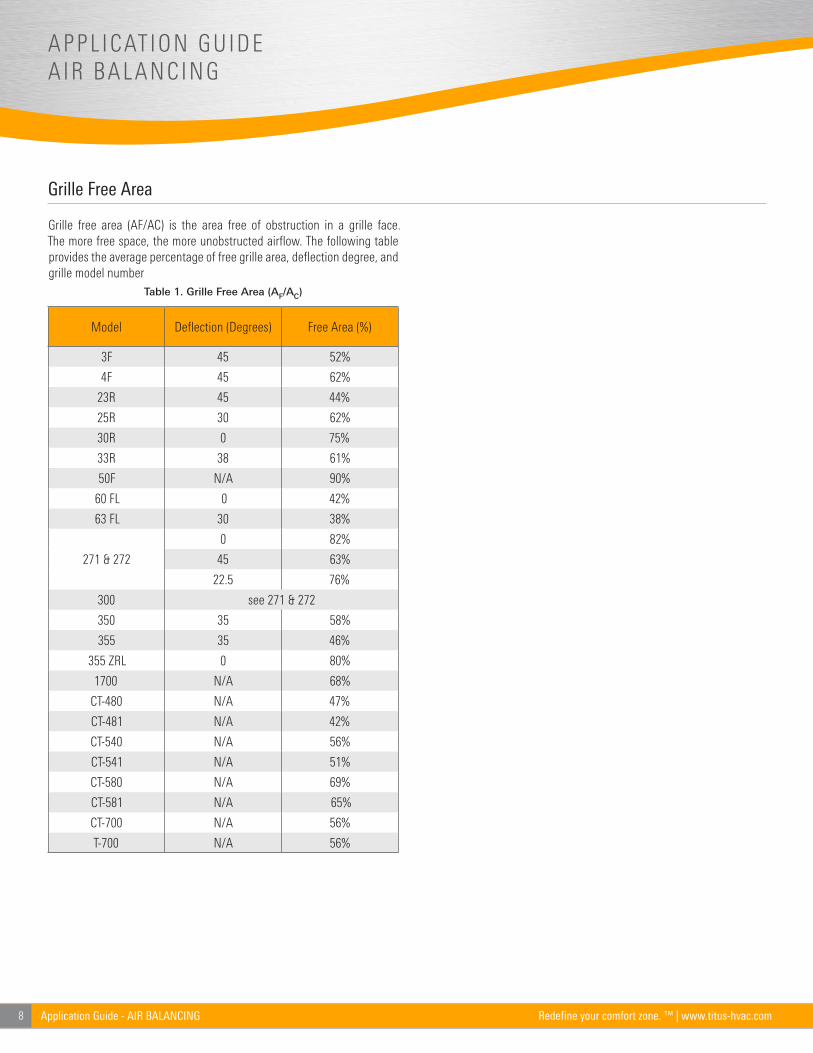
Grille Free Area
Grille free area (AF/AC) is the area free of obstruction in a grille face. The more free space, the more unobstructed airflow. The following table provides the average percentage of free grille area, deflection degree, and grille model number
Table 1. Grille Free Area (AF/AC)
Model Deflection (Degrees) Free Area (%)
3F 45 52%
4F 45 62%
23R 45 44%
25R 30 62%
30R 0 75%
33R 38 61%
50F N/A 90%
60 FL 0 42%
63 FL 30 38%
271 & 272
0 82%
45 63%
22.5 76%
300 see 271 & 272
350 35 58%
355 35 46%
355 ZRL 0 80%
1700 N/A 68%
CT-480 N/A 47%
CT-481 N/A 42%
CT-540 N/A 56%
CT-541 N/A 51%
CT-580 N/A 69%
CT-581 N/A 65%
CT-700 N/A 56%
T-700 N/A 56%

9Application Guide - AIR BALANCINGRedefine your comfort zone. ™ | www.titus-hvac.com
Cross Reference
Table 2 provides a listing of products and their respective flow factor document.
Table 2. Product Cross Reference of Flow Factors
Product See Flow Factor… Product See Flow Factor…30 272-FF CT-580 CT-FF
111 272-FF CT-581 CT-FF
112 272-FF CT-700 T700-FF
121 272-FF CT-700 Core 272-FF
122 272-FF DL DL-FF
131 272-FF FlowBar FB-FF
132 272-FF FR-1, -2, -3, -4 FR-FF
271 272-FF LL-1 LL1-FF
272 272-FF LL-2 LL2-FF
1700 1700-FF ML-37 ML-FF
23 - Core 272-FF ML-38 ML-FF
25 - Core 272-FF ML-39 ML-FF
250 1-way 250-FF N-1 N1-FF
250 2-way 250-FF N-1-DR N1DR-FF
250 3-way 250-FF OMNI OMNI-FF
250 4-way 250-FF F PAR PAR-F
3 - Core 272-FF PAS PAS-FF
30 - Core 272-FF PDR PAR-FF
300FL 272-FF PDS PAS-FF
300FS 272-FF PFR PFS-FF
300HD 300HD-FF PFS PFS-FF
300RL 272-FF PSS PSS-FF
300RS 272-FF R-OMNI R-OMNI-FF
301FL F 272-FF SG-SD SGSD-F
301FS 272-FF T700 T700-F
301RL 272-FF T700 - Core 272-FF
301RS 272-FF TBD-10 TBD-10-F
33 - Core 272-FF TBD-30 TBD-30-FF
34 - Core 272-FF TBD-80 TBD-80-FF
350FL Core 272-FF TBDI-10 TBD-10-F
350FS Core 272-FF TBDI-30 TBD-30-FF
350RL Core 272-FF TBDI-80 TBD-80-FF
350RS Core 272-FF TDC TDC-FF
355 272-FF TBF TBF-FF
4 - Core 272-FF TLF TLF-FF
50 - Core 272-FF TMR TMR-FF
50F 50-FF TMRA TMRA-FF
8 - Core 272-FF TMR-AA TMR-FF
CT-480 CT-FF TMRA-AA TMRA-FF
CT-481 CT-FF TMS TMS-FF
CT-540 CT-FF TMSA TMSA-FF
CT-541 CT-FF XC-310 XC310-FF

10 Application Guide - AIR BALANCING Redefine your comfort zone. ™ | www.titus-hvac.com
APPLICATION GUIDEAIR BALANCING
System Balancing Worksheet
Outlet Product Information
Outlet No.
OutletK-Factor
Design
Type Size CFM VD
1
2
3
4
5
6
7
8
9
10
11
12
13
14
15
Adjustments
I II III iv
VM R VM R VM R VM R
1A
1B
2A
2B
3A
3B
4A
4B
5A
5B
6A
6B
7A
7B
8A
8B
9A
9B
10A
10B
11A
11B
12A
12B
13A
13B
14A
14B
15A
15B

11Application Guide - AIR BALANCINGRedefine your comfort zone. ™ | www.titus-hvac.com
Notes

605 Shiloh RdPlano TX 75074ofc: 972.212.4800fax: 972.212.4884
Redefine your comfort zone. ™ | www.titus-hvac.com