aii33024 backup sensor - college hills · pdf file© 2006 american honda motor co., inc. -...
TRANSCRIPT
© 2006 American Honda Motor Co., Inc. - All Rights Reserved. AII 33024 (0607) 1 of 1208V67-SHJ-1000-91
INSTALLATIONINSTRUCTIONS
Accessory Application Publications No.
Issue Date
JULY 2006
2007 ODYSSEYBACKUP SENSOR
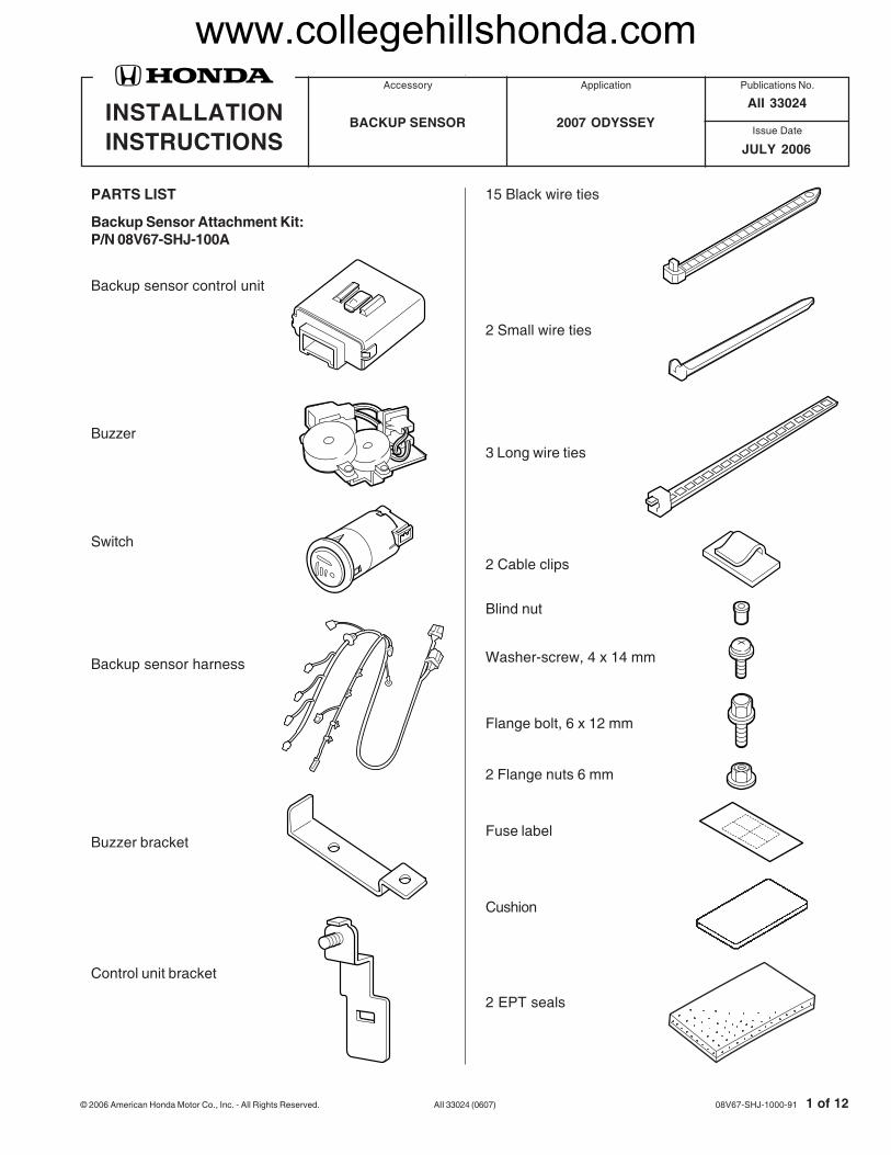
PARTS LIST
Backup Sensor Attachment Kit:P/N 08V67-SHJ-100A
Backup sensor control unit
Switch
Buzzer bracket
Buzzer
Backup sensor harness
Control unit bracket
15 Black wire ties
2 Small wire ties
3 Long wire ties
2 Cable clips
Blind nut
Washer-screw, 4 x 14 mm
Flange bolt, 6 x 12 mm
2 Flange nuts 6 mm
Fuse label
Cushion
2 EPT seals
AII 33024
www.collegehillshonda.com

2 of 12 AII 33024 (0607) © 2006 American Honda Motor Co., Inc. - All Rights Reserved.
TOOLS AND SUPPLIES REQUIRED#2 Phillips screwdriverSmall flat-tip screwdriverFelt-tip pen10 mm Combination wrench10 mm and 14 mm SocketPushpinRatchet3 mm, 8 mm, Drill bitEye protection (face shield, safety goggles, etc.)FileDiagonal cuttersScissorsMasking tapeTape measureCardboardIsopropyl alcoholShop towel22 mm and 26 mm HolesawsDrillUtility knife
Backup Sensor Kit:P/N 08V67-SHJ-1XX
NOTE: Refer to Parts Information Bulletin (PIB)A04-0024 for the proper color sensors.
2 Corner sensors
2 Center sensors
Illustration of the Backup Sensor Installed on theVehicle
4318010Y
SWITCH
BUZZER
CORNERSENSOR
BACKUPSENSORHARNESS
CENTERSENSOR
CORNERSENSOR
CONTROLUNIT
INSTALLATION
Customer Information: The information in thisinstallation instruction is intended for use only byskilled technicians who have the proper tools,equipment, and training to correctly and safely addequipment to your vehicle. These proceduresshould not be attempted by “do-it-yourselfers.”
1. Make sure you have the anti-theft code for theradio, then write down the radio station presets.
2. Disconnect the negative cable from the battery.
2 Spacers
www.collegehillshonda.com

© 2006 American Honda Motor Co., Inc. - All Rights Reserved. AII 33024 (0607) 3 of 12
3. Remove the rear bumper:
• Remove the three clips along the bottom of thebumper.
• Remove the six screws (three on each side)from the fenderwell area.
• Using a flat-tip screwdriver, pry out andremove the bumper bolt covers, then removethe four bumper bolts.
• With the help of an assistant, release thebumper from the fenderwell, and slide thebumper away from the vehicle.
• Set the bumper on a blanket.
4. Remove the driver’s sliding door sill trim (fiveclips).
5. Pull away the weatherstrip from the rear trimpanel. Remove the rear trim panel (ten clips andtwo screws).
6. Remove the spare tire cover (17 tabs).
SELF-TAPPINGSCREWS (6)
BUMPERBOLTCOVERS(4)
CLIPS (3)
BUMPERBOLTS (4)
REARBUMPER
4318020Y
CLIPS (5)
DRIVER’S SLIDINGDOOR SILL TRIM
4122011Y
SPARE TIRECOVER
LEFT REAR SIDETRIM PANEL
TABS (17)
4122041Y
CLIPS(10)
REAR TRIM PANEL
SCREW
SCREW
WEATHERSTRIP
www.collegehillshonda.com

4 of 12 AII 33024 (0607) © 2006 American Honda Motor Co., Inc. - All Rights Reserved.
7. Remove the anchor bolt and the anchor bolt cover,and take out the spare tire.
9. Remove the left second row seat belt upperanchor cover (two tabs). Remove the left secondrow seat belt upper anchor bolt.
10. Pull away the weatherstrip from the left quarterpillar trim. Remove the left quarter pillar trim (twotabs and clip).
8. Remove the jack cover (2 tabs).
4122020Y
SPARE TIRE
ANCHORBOLTCOVER
ANCHORBOLT
4508020Y
LEFT SECOND ROWSEAT BELT UPPERANCHOR BOLT
LEFT SECOND ROWSEAT BELT UPPERANCHOR COVER
TAB
4708010Y
JACKCOVER
LEFT REARSIDE PANEL
TABS (2)
4510010YTAB
SRSCLIP
LEFT QUARTERPILLAR TRIM
WEATHERSTRIP
www.collegehillshonda.com

© 2006 American Honda Motor Co., Inc. - All Rights Reserved. AII 33024 (0607) 5 of 12
• Pull away the weatherstrip from the left rearside trim panel, and remove the rear bolt.
• Remove the second row seat belt loweranchor bolt.
• Gently pull the panel out towards you torelease the eight clips and four tabs, releasethe third row seat belt through the slit in thepanel, and disconnect the rear accessorysocket connector.
11. Remove the left rear side trim panel:
• Remove the third row seat rail cover (threeclips).
13. EX Model Only: Remove the two self-tappingscrews, disengage the retaining tab, and pull outthe power door control unit. Move the control unitout of the way.
12. Remove the left rear pillar trim (one cover, onebolt, one clip, two tabs).
CLIP
TAB
BOLT
LEFT REARPILLAR TRIM
COVER
4318040YSELF-TAPPINGSCREW
LEFT SIDEREAR PANEL
POWER DOORCONTROL UNIT
4122030Y�
CLIPS (8)TABS (4)
LEFT REARSIDE TRIMPANEL
SECOND ROWSEAT BELT LOWERANCHOR BOLT
LEFT REARSIDE TRIMPANEL
WEATHERSTRIP
ACCESSORYSOCKETCONNECTOR
4510020Y
THIRD ROW SEATRAIL COVERCLIPS (3)
LEFT REARSIDE TRIM THIRD ROW
SEAT
www.collegehillshonda.com

6 of 12 AII 33024 (0607) © 2006 American Honda Motor Co., Inc. - All Rights Reserved.
15. Install the buzzer bracket to the buzzer using the6 x 12 mm flange bolt and a 6 mm flange nut.
17. Install the blind nut into the 8 mm hole you drilled.Attach the buzzer to the vehicle panel using the4 x 14 mm washer screw.
4318070Y
VEHICLEPANEL
BLIND NUT
4 x 14 mmWASHERSCREW
BUZZER
16. Using isopropyl alcohol, thoroughly clean the areawhere the cushion tape will attach. Usingscissors, cut a cushion tape in half. Attach one ofthe two halves to the buzzer bracket.
4510030Y
CUSHION TAPE(Cut in half.)
CUSHIONTAPE BUZZER
BRACKET
BUZZER
SIDE VIEW
BUZZER
BUZZERBRACKET
CUSHIONTAPE
4318061Y
6 x 12 mmFLANGEBOLT
6 mmFLANGE NUT
BUZZERBRACKET
BUZZER
14. At the left rear panel area, enlarge the panel holeto 8 mm. While wearing eye protection, drill thebody panel using an 8 mm drill bit and a drill stop.
4318050Y
DRILL(8 mm drill bit)
10 mmTAPE
VEHICLEPANEL
www.collegehillshonda.com
© 2006 American Honda Motor Co., Inc. - All Rights Reserved. AII 33024 (0607) 7 of 12
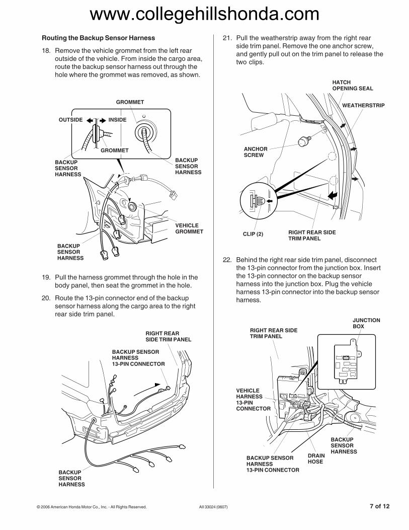
22. Behind the right rear side trim panel, disconnectthe 13-pin connector from the junction box. Insertthe 13-pin connector on the backup sensorharness into the junction box. Plug the vehicleharness 13-pin connector into the backup sensorharness.
21. Pull the weatherstrip away from the right rearside trim panel. Remove the one anchor screw,and gently pull out on the trim panel to release thetwo clips.
Routing the Backup Sensor Harness
18. Remove the vehicle grommet from the left rearoutside of the vehicle. From inside the cargo area,route the backup sensor harness out through thehole where the grommet was removed, as shown.
19. Pull the harness grommet through the hole in thebody panel, then seat the grommet in the hole.
20. Route the 13-pin connector end of the backupsensor harness along the cargo area to the rightrear side trim panel.
4508010Y
RIGHT REAR SIDETRIM PANEL
CLIP (2)
HATCHOPENING SEAL
ANCHORSCREW
WEATHERSTRIP
4318082Y�
GROMMET
BACKUPSENSORHARNESS
VEHICLEGROMMET
OUTSIDE INSIDE
GROMMET
BACKUPSENSORHARNESS
BACKUPSENSORHARNESS
4318101Y
JUNCTIONBOX
RIGHT REAR SIDETRIM PANEL
BACKUPSENSORHARNESS
BACKUP SENSORHARNESS13-PIN CONNECTOR
VEHICLEHARNESS13-PINCONNECTOR
DRAINHOSE
4318090YBACKUPSENSORHARNESS
BACKUP SENSORHARNESS13-PIN CONNECTOR
RIGHT REARSIDE TRIM PANEL
www.collegehillshonda.com

8 of 12 AII 33024 (0607) © 2006 American Honda Motor Co., Inc. - All Rights Reserved.
25. On the driver’s side of the vehicle, attach thebackup sensor harness ground terminal using thevehicle ground bolt.
24. Secure the backup sensor harness to the vehicleharness with five wire ties.
23. Route the backup sensor harness under the drainhose, and secure the backup sensor harness tothe vehicle harness with two wire ties.
26. Install the 2A fuse label to the fuse case.
27. Secure the backup sensor harness to the vehicleharness with three wire ties.
28. Get the backup sensor control unit and thecontrol unit bracket. Install the control unit bracketto the control unit.
4318111Y
WIRE TIE
BACKUPSENSORHARNESS
VEHICLEHARNESS
JUNCTIONBOX
DRAIN HOSE
4318131YBACKUPSENSORHARNESS
WIRE TIE WIRE TIE
VEHICLEHARNESSFUSE
CASE2A FUSELABEL
VEHICLEGROUNDTERMINAL
VEHICLEGROUNDBOLT
POWERDOORCONTROLUNIT (EX,and EX-LMODELS)
4318120Y
WIRE TIE
BACKUPSENSORHARNESS
VEHICLEHARNESS
4318150Y
BACKUP SENSORCONTROL UNIT
CONTROLUNITBRACKET
www.collegehillshonda.com
© 2006 American Honda Motor Co., Inc. - All Rights Reserved. AII 33024 (0607) 9 of 12
4319033Y
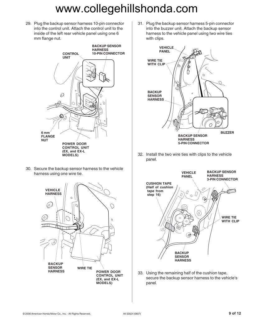
30. Secure the backup sensor harness to the vehicleharness using one wire tie.
31. Plug the backup sensor harness 5-pin connectorinto the buzzer unit. Attach the backup sensorharness to the vehicle panel using two wire tieswith clips.
32. Install the two wire ties with clips to the vehiclepanel.
29. Plug the backup sensor harness 10-pin connectorinto the control unit. Attach the control unit to theinside of the left rear vehicle panel using one 6mm flange nut.
33. Using the remaining half of the cushion tape,secure the backup sensor harness to the vehicle'spanel.
WIRE TIEWITH CLIP
BACKUPSENSORHARNESS
VEHICLEPANEL
BACKUP SENSORHARNESS3-PIN CONNECTOR
CUSHION TAPE(Half of cushiontape fromstep 16)
4319010Y
VEHICLEHARNESS
BACKUPSENSORHARNESS
WIRE TIEPOWER DOORCONTROL UNIT(EX, and EX-LMODELS)
4319022Y
BACKUP SENSORHARNESS5-PIN CONNECTOR
WIRE TIEWITH CLIP
BUZZER
VEHICLEPANEL
BACKUPSENSORHARNESS
4318161Y
BACKUP SENSORHARNESS10-PIN CONNECTORCONTROL
UNIT
6 mmFLANGENUT
POWER DOORCONTROL UNIT(EX, and EX-LMODELS)
www.collegehillshonda.com

10 of 12 AII 33024 (0607) © 2006 American Honda Motor Co., Inc. - All Rights Reserved.
36. Remove the bumper beam support.
35. Using scissors, cut two EPT sealers in half.Attach one cut EPT sealer piece at each greentape location on the backup sensor harness.
34. Using isopropyl alcohol, clean the areas where thecable clips will attach. On the outside of thevehicle, route the backup sensor harness acrossthe back of the vehicle. Secure the backup sensorharness to the vehicle panel and to the bumperbeam with two cable clips and two small wire ties.
37. Route the backup sensor harness along thebumper beam. Secure the backup sensor harnessto the bumper beam using three long wire ties.
38. Reinstall the bumper beam support.
Installing the Switch
39. On the inside of the left rear pillar trim, measureand mark the pillar trim at the measurementsshown. Measure from the base of the ribs. Whilewearing eye protection, drill a 26 mm hole at themarked position.
4319041Y
GREEN TAPE
BACKUPSENSORHARNESS
GREEN TAPESMALLWIRE TIES(2)
BACKUPSENSORHARNESS
VEHICLEPANEL
CABLECLIPS (2)
4510040Y
EPT SEALER(Cut in half.)
EPT SEALERS (3)
BACKUPSENSORHARNESS
GREENTAPE
GREENTAPE
GREENTAPE
4319052Y
LONGWIRE TIE
BACKUPSENSORHARNESS
BACKUP SENSORHARNESS 2-PINCONNECTORS
BUMPERBEAM
EPT SEALERS (3)
BUMPERBEAMSUPPORT
4319061Y
26 mm HOLE SAW
24 mm
18 mm
LEFT REARPILLAR TRIM
www.collegehillshonda.com

© 2006 American Honda Motor Co., Inc. - All Rights Reserved. AII 33024 (0607) 11 of 12
41. Plug the backup sensor harness 3-pin connectorinto the switch, and reinstall the left rear pillartrim.
Installing the Backup Sensors
42. On the inside of the rear bumper, locate the fourscribe marks. Using a pushpin, mark the bumperat each of the four locations. When you mark thebumper with a pushpin, be careful not to piercethrough the other marks.
40. Install the switch into the hole in the left rear pillartrim in the direction shown.
43. While wearing eye protection, drill a 22 mm holethrough the outboard marks, and drill a 26 mmhole through the two inboard marks. Remove anyburrs.
UP
DOWN
4319083Y
22 mmHOLE SAW
26 mmHOLE SAW
PUSHPIN
PUSHPIN
REARBUMPER
MARK FORBACKUP SENSOR(Mark in the sameposition of theother side.)
MARK FORBACKUP SENSOR(Mark in the sameposition of theother side.)
MARK NOT USED(Do not piercethrough themark.)
MARK NOT USED(Do not piercethrough thesemarks.)
4319110Y
SWITCH
BACKUPSENSORHARNESS3-PINCONNECTOR
LEFT REARPILLAR TRIM
4319070Y
SWITCH
LEFT REARPILLAR TRIM
SWITCH
26 mm HOLE
www.collegehillshonda.com

12 of 12 AII 33024 (0607) © 2006 American Honda Motor Co., Inc. - All Rights Reserved.
47. Check that all wire harnesses are routed properly,and that all connectors are plugged in.
48. Reinstall all removed parts.
49. Reconnect the negative cable to the battery.
50. Enter the customer’s radio anti-theft code, andreset the radio station presets.
51. Reset the clock.
52. Check the operation of the backup sensors asdescribed in the backup sensor owner’s manualsupplied.
NOTE: Whenever the battery is disconnected, thedriver’s AUTO function is disabled.
53. Start the engine. Push down on the driver'swindow switch until the window is fully open, thenhold the switch for 2 seconds or more.
54. Pull up on the driver’s window switch to close thewindow completely.
55. Test the driver’s AUTO window function.
44. Install the two corner sensors and the two centersensors into the rear bumper with the arrow onthe sensors facing up. Do not to push on themicrophone when installing the sensors.
46. With the help of an assistant, connect the 2-pinconnectors from the backup sensor harness to thesensors, then reinstall the bumper.
45. On the inside of the bumper, install the twospacers on the center sensors.
4319100Y
CENTERSENSOR 2-PINCONNECTOR
BACKUP SENSORHARNESS2-PINCONNECTOR
CORNERSENSOR2-PINCONNECTOR
CORNERSENSOR2-PINCONNECTOR
BACKUPSENSORHARNESS2-PINCONNECTOR
REAR BUMPER
4319093Y
CORNERSENSOR
CENTERSENSORCORNER
SENSOR
REARBUMPER
UP
DOWN
SPACER
MICROPHONE
HOUSING
www.collegehillshonda.com