aii 24282 cd changer - handa- · pdf filecd changer element parts list ... aii 24282. ......
TRANSCRIPT

© 2002 American Honda Motor Co., Inc - All Rights Reserved. AII 24282 (0212) 1 of 1308B26-SCV-1000-91
INSTALLATIONINSTRUCTIONS
Accessory Application Publications No.
Issue Date
DEC 2002
ELEMENTCD CHANGER
PARTS LIST
CD Changer Attachment Kit:P/N 08B26-SCV-100
2 Screw-grommets
2 Self-tapping screws
7 Washer-screws, 4 x 8 mm
6 Flange nuts, 6 mm
2 Washer-bolts, 6 x 12 mm
10 Wire ties
6 EPT Sealer
6 Cushion tapes
2 Harness clip
2 Wire ties with clip
User information
CD changer plate
Right base bracket
Left base bracket
Right side bracket
Left side bracket
BUS cable
Harness clamp bracket
Connector clip
AII 24282
2 of 13 AII 24282 (0212) © 2002 American Honda Motor Co., Inc - All Rights Reserved.
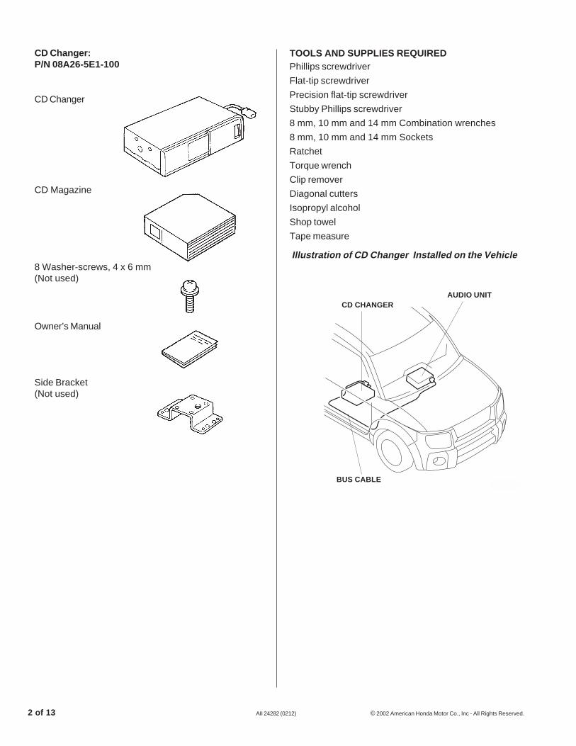
CD Changer:P/N 08A26-5E1-100
CD Changer
CD Magazine
8 Washer-screws, 4 x 6 mm(Not used)
Owner’s Manual
Side Bracket(Not used)
TOOLS AND SUPPLIES REQUIREDPhillips screwdriver
Flat-tip screwdriver
Precision flat-tip screwdriver
Stubby Phillips screwdriver
8 mm, 10 mm and 14 mm Combination wrenches
8 mm, 10 mm and 14 mm Sockets
Ratchet
Torque wrench
Clip remover
Diagonal cutters
Isopropyl alcohol
Shop towel
Tape measure
Illustration of CD Changer Installed on the Vehicle
2712020K
CD CHANGERAUDIO UNIT
BUS CABLE
© 2002 American Honda Motor Co., Inc - All Rights Reserved. AII 24282 (0212) 3 of 13
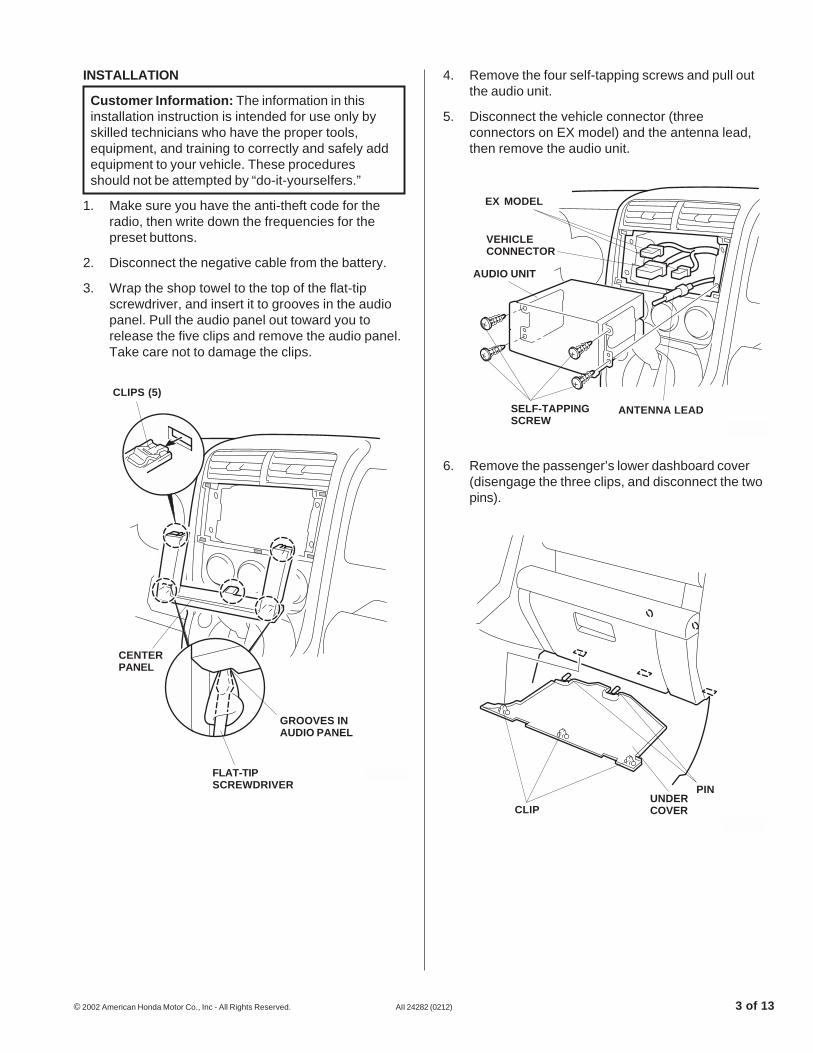
6. Remove the passenger’s lower dashboard cover(disengage the three clips, and disconnect the twopins).
4. Remove the four self-tapping screws and pull outthe audio unit.
5. Disconnect the vehicle connector (threeconnectors on EX model) and the antenna lead,then remove the audio unit.
INSTALLATION
Customer Information: The information in thisinstallation instruction is intended for use only byskilled technicians who have the proper tools,equipment, and training to correctly and safely addequipment to your vehicle. These proceduresshould not be attempted by “do-it-yourselfers.”
1. Make sure you have the anti-theft code for theradio, then write down the frequencies for thepreset buttons.
2. Disconnect the negative cable from the battery.
3. Wrap the shop towel to the top of the flat-tipscrewdriver, and insert it to grooves in the audiopanel. Pull the audio panel out toward you torelease the five clips and remove the audio panel.Take care not to damage the clips.
2624042K
CENTERPANEL
CLIPS (5)
FLAT-TIPSCREWDRIVER
GROOVES INAUDIO PANEL
2625031K
VEHICLECONNECTOR
ANTENNA LEADSELF-TAPPINGSCREW
AUDIO UNIT
EX MODEL
2904021K
CLIPUNDERCOVER
PIN
4 of 13 AII 24282 (0212) © 2002 American Honda Motor Co., Inc - All Rights Reserved.
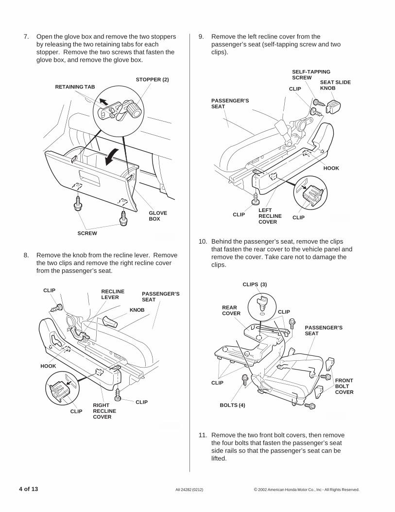
11. Remove the two front bolt covers, then removethe four bolts that fasten the passenger’s seatside rails so that the passenger’s seat can belifted.
10. Behind the passenger’s seat, remove the clipsthat fasten the rear cover to the vehicle panel andremove the cover. Take care not to damage theclips.
9. Remove the left recline cover from thepassenger’s seat (self-tapping screw and twoclips).
8. Remove the knob from the recline lever. Removethe two clips and remove the right recline coverfrom the passenger’s seat.
7. Open the glove box and remove the two stoppersby releasing the two retaining tabs for eachstopper. Remove the two screws that fasten theglove box, and remove the glove box.
2710030K
CLIPS (3)
CLIP
FRONTBOLTCOVER
BOLTS (4)
CLIP
REARCOVER
PASSENGER’SSEAT
2710040K
RETAINING TABSTOPPER (2)
GLOVEBOX
SCREW
2711021K
RECLINELEVER
KNOB
RIGHTRECLINECOVER
CLIP
CLIP
CLIP
HOOK
PASSENGER’SSEAT
2711032K
CLIP
CLIPLEFTRECLINECOVER
SELF-TAPPINGSCREW
SEAT SLIDEKNOB
HOOK
CLIP
PASSENGER’SSEAT

© 2002 American Honda Motor Co., Inc - All Rights Reserved. AII 24282 (0212) 5 of 13
Routing the BUS Cable
14. From the center dashboard opening, route theBUS cable toward the glove box opening alongthe antenna lead.
13. Pull up the door opening trim, and remove thepassenger’s kick panel (pull the kick panel outtoward you to release the two clips and twohooks). Take care not to damage the clips andhooks.
12. Remove the passenger’s sill trim (ten clips andtwo retaining tabs). Take care not to damage theclips and retaining tabs.
2710010K
CLIPS (10) PASSENGER’SSILL TRIM RETAINING
TAB
RETAININGTAB
2710020K
PASSENGER’SKICK PANEL
HOOK
CLIPS (2)
DOOROPENINGTRIM
2710052K
ANTENNALEAD
WIRE TIE
BUS CABLE14-PIN CONNECTOR(Align the BUS cable14-pin connector withthe antenna lead.)
VEHICLECONNECTOR
AUDIO(Take care to avoidcontact with theaudio unit.)
VEHICLEHARNESS
BUSCABLE
BUS CABLE14-PINCONNECTOR
15. Pull the BUS cable 14-pin connector out from thecenter dashboard opening and adjust the cable sothat the distance from the center dashboardopening to the end of the 14-pin connector is100 mm. Secure the BUS cable to the vehicleharness with one wire tie as shown.

6 of 13 AII 24282 (0212) © 2002 American Honda Motor Co., Inc - All Rights Reserved.
Without Amplifier:
Using isopropyl alcohol, thoroughly clean thevehicle panel in the area shown, then secure theBUS cable to the vehicle panel with the twocushion tapes.
17. Continue routing the BUS cable downward andattach it with wire ties or cushion tape.
With Amplifier:
Secure the BUS cable to the amplifier harnesswith the wire ties in the areas shown.
16. Continue routing the BUS cable along thedashboard frame, and secure it to the antennalead with the four wire ties in the areas shown.Point the connection part of the two wire tiesupward as shown.
2712012K
WIRE TIES(Attach to theantenna lead.)
EPT SEALER
Pass onthe inside.
DASHBOARDFRAME
DASHBOARDFRAME
BUS CABLE
WIRE TIE
ANTENNALEAD
2710061K
VEHICLEAMPLIFIER
WIRETIE
SIDE STEP
BUS CABLE
2710070K
VEHICLEPANEL
BUS CABLE
CUSHIONTAPE
SIDE STEP
© 2002 American Honda Motor Co., Inc - All Rights Reserved. AII 24282 (0212) 7 of 13
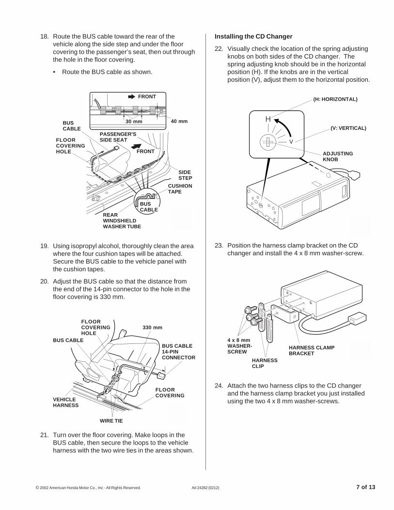
21. Turn over the floor covering. Make loops in theBUS cable, then secure the loops to the vehicleharness with the two wire ties in the areas shown.
19. Using isopropyl alcohol, thoroughly clean the areawhere the four cushion tapes will be attached.Secure the BUS cable to the vehicle panel withthe cushion tapes.
20. Adjust the BUS cable so that the distance fromthe end of the 14-pin connector to the hole in thefloor covering is 330 mm.
18. Route the BUS cable toward the rear of thevehicle along the side step and under the floorcovering to the passenger’s seat, then out throughthe hole in the floor covering.
• Route the BUS cable as shown.
2710081K
SIDESTEP
CUSHIONTAPE
REARWINDSHIELDWASHER TUBE
FLOORCOVERINGHOLE
BUSCABLE
30 mm 40 mm
FRONT
FRONT
PASSENGER’SSIDE SEAT
BUSCABLE
Installing the CD Changer
22. Visually check the location of the spring adjustingknobs on both sides of the CD changer. Thespring adjusting knob should be in the horizontalposition (H). If the knobs are in the verticalposition (V), adjust them to the horizontal position.
24. Attach the two harness clips to the CD changerand the harness clamp bracket you just installedusing the two 4 x 8 mm washer-screws.
23. Position the harness clamp bracket on the CDchanger and install the 4 x 8 mm washer-screw.
2710100K
(H: HORIZONTAL)
(V: VERTICAL)
ADJUSTINGKNOB
2710110K
4 x 8 mmWASHER-SCREW
HARNESSCLIP
HARNESS CLAMPBRACKET
2710091K
BUS CABLE14-PINCONNECTOR
FLOORCOVERINGHOLE
FLOORCOVERING
WIRE TIE
VEHICLEHARNESS
BUS CABLE
330 mm
8 of 13 AII 24282 (0212) © 2002 American Honda Motor Co., Inc - All Rights Reserved.
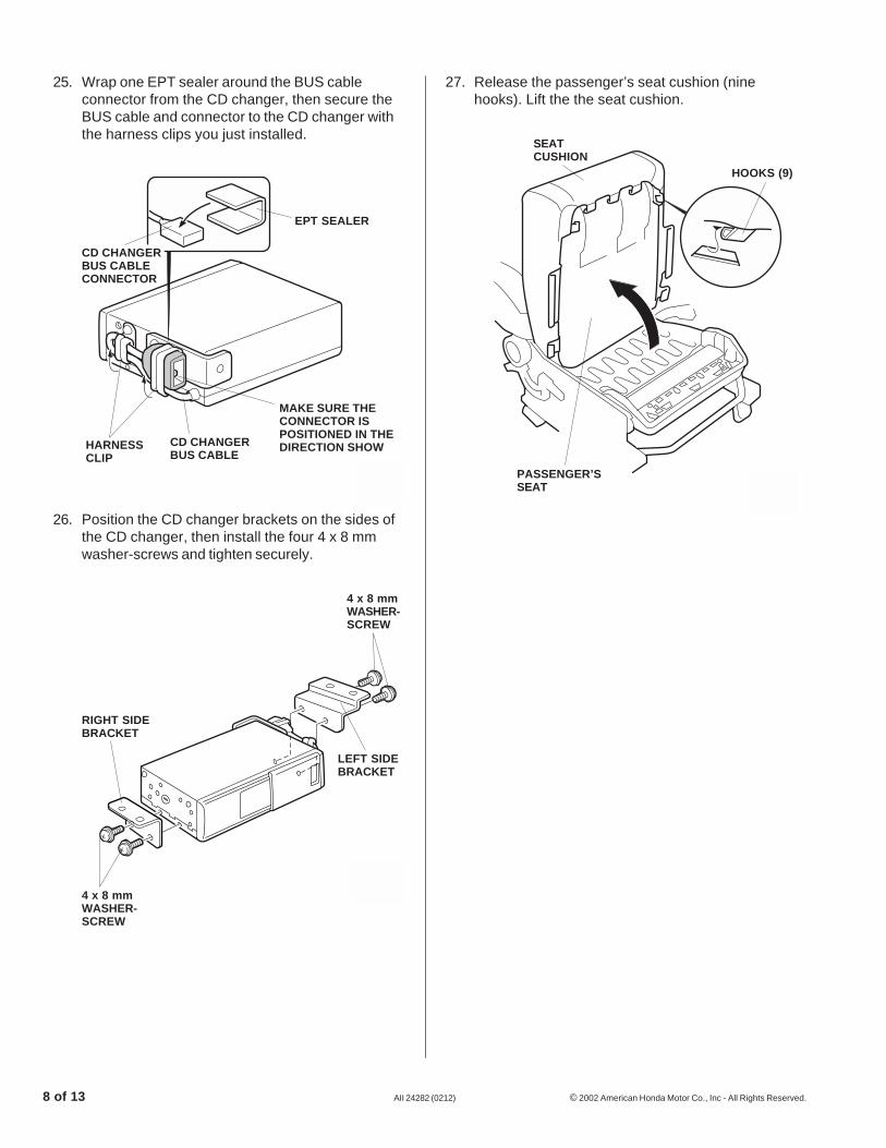
27. Release the passenger’s seat cushion (ninehooks). Lift the the seat cushion.
26. Position the CD changer brackets on the sides ofthe CD changer, then install the four 4 x 8 mmwasher-screws and tighten securely.
25. Wrap one EPT sealer around the BUS cableconnector from the CD changer, then secure theBUS cable and connector to the CD changer withthe harness clips you just installed.
2710121K
EPT SEALER
HARNESSCLIP
CD CHANGERBUS CABLE
MAKE SURE THECONNECTOR ISPOSITIONED IN THEDIRECTION SHOW
CD CHANGERBUS CABLECONNECTOR
2711010K
RIGHT SIDEBRACKET
4 x 8 mmWASHER-SCREW
4 x 8 mmWASHER-SCREW
LEFT SIDEBRACKET
2903090K
HOOKS (9)
SEATCUSHION
PASSENGER’SSEAT
© 2002 American Honda Motor Co., Inc - All Rights Reserved. AII 24282 (0212) 9 of 13
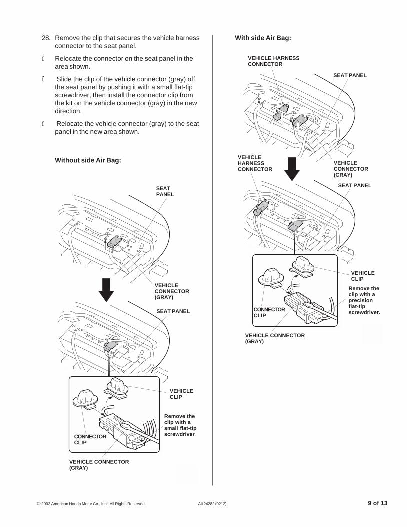
With side Air Bag:28. Remove the clip that secures the vehicle harnessconnector to the seat panel.
ï Relocate the connector on the seat panel in thearea shown.
ï Slide the clip of the vehicle connector (gray) offthe seat panel by pushing it with a small flat-tipscrewdriver, then install the connector clip fromthe kit on the vehicle connector (gray) in the newdirection.
ï Relocate the vehicle connector (gray) to the seatpanel in the new area shown.
Without side Air Bag:
2923010K
SEATPANEL
VEHICLECONNECTOR(GRAY)
SEAT PANEL
VEHICLECLIP
Remove theclip with asmall flat-tipscrewdriver
VEHICLE CONNECTOR(GRAY)
CONNECTORCLIP
2711052K
VEHICLE HARNESSCONNECTOR
SEAT PANEL
VEHICLECONNECTOR(GRAY)
VEHICLEHARNESSCONNECTOR
SEAT PANEL
VEHICLECLIP
Remove theclip with aprecisionflat-tipscrewdriver.
VEHICLE CONNECTOR(GRAY)
CONNECTORCLIP
10 of 13 AII 24282 (0212) © 2002 American Honda Motor Co., Inc - All Rights Reserved.
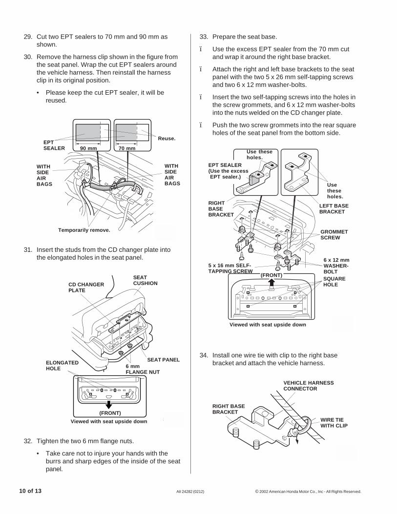
34. Install one wire tie with clip to the right basebracket and attach the vehicle harness.
31. Insert the studs from the CD changer plate intothe elongated holes in the seat panel.
32. Tighten the two 6 mm flange nuts.
• Take care not to injure your hands with theburrs and sharp edges of the inside of the seatpanel.
29. Cut two EPT sealers to 70 mm and 90 mm asshown.
30. Remove the harness clip shown in the figure fromthe seat panel. Wrap the cut EPT sealers aroundthe vehicle harness. Then reinstall the harnessclip in its original position.
• Please keep the cut EPT sealer, it will bereused.
2711060KViewed with seat upside down
6 mmFLANGE NUT
SEAT PANELELONGATEDHOLE
CD CHANGERPLATE
SEATCUSHION
(FRONT)
2903110K
RIGHT BASEBRACKET
VEHICLE HARNESSCONNECTOR
WIRE TIEWITH CLIP
2903100K
EPTSEALER 90 mm 70 mm
Temporarily remove.
Reuse.
WITHSIDEAIRBAGS
WITHSIDEAIRBAGS
33. Prepare the seat base.
ï Use the excess EPT sealer from the 70 mm cutand wrap it around the right base bracket.
ï Attach the right and left base brackets to the seatpanel with the two 5 x 26 mm self-tapping screwsand two 6 x 12 mm washer-bolts.
ï Insert the two self-tapping screws into the holes inthe screw grommets, and 6 x 12 mm washer-boltsinto the nuts welded on the CD changer plate.
ï Push the two screw grommets into the rear squareholes of the seat panel from the bottom side.
2711071KViewed with seat upside down
Usetheseholes.
Use theseholes.
SQUAREHOLE
6 x 12 mmWASHER-BOLT
5 x 16 mm SELF-TAPPING SCREW
LEFT BASEBRACKET
GROMMETSCREW
(FRONT)
RIGHTBASEBRACKET
EPT SEALER(Use the excessEPT sealer.)
© 2002 American Honda Motor Co., Inc - All Rights Reserved. AII 24282 (0212) 11 of 13
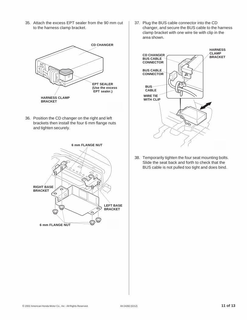
36. Position the CD changer on the right and leftbrackets then install the four 6 mm flange nutsand tighten securely.
35. Attach the excess EPT sealer from the 90 mm cutto the harness clamp bracket.
38. Temporarily tighten the four seat mounting bolts.Slide the seat back and forth to check that theBUS cable is not pulled too tight and does bind.
37. Plug the BUS cable connector into the CDchanger, and secure the BUS cable to the harnessclamp bracket with one wire tie with clip in thearea shown.
2711092K
CD CHANGERBUS CABLECONNECTOR
BUS CABLECONNECTOR
BUSCABLE
HARNESSCLAMPBRACKET
WIRE TIEWITH CLIP
2927090K
CD CHANGER
EPT SEALER(Use the excessEPT sealer.)
HARNESS CLAMPBRACKET
2711080K
6 mm FLANGE NUT
LEFT BASEBRACKET
6 mm FLANGE NUT
RIGHT BASEBRACKET

12 of 13 AII 24282 (0212) © 2002 American Honda Motor Co., Inc - All Rights Reserved.
Connecting the BUS Cable and Audio Unit
43. Plug the BUS cable 14-pin connector, the vehicle20-pin connector, and antenna lead into the backof the AM/FM CD Tuner.
with MP3 player:
2626071K
AM/FMCD TUNER
BUS CABLE14-PINCONNECTOR
VEHICLE20-PINCONNECTOR
ANTENNALEAD
MP3PLAYER
2711100K
AM/FMCD TUNER
BUS CABLE14-PINCONNECTOR
VEHICLE 20-PINCONNECTOR
ANTENNALEAD
42. Reinstall the bolt covers.
40. Attach the EPT sealer at the location where theBUS harness and the seat panel may interferewith each other.
41. Torque the seat mounting bolts to 31-37 N·m(23- 27 lb-ft).
39. Attach the vehicle harness to BUS cable with onewire tie.
2904012K
VEHICLEHARNESSCONNECTOR
EPT SEALER
SEAT PANEL
CD CHANGER
BUS CABLE
2710030K
CLIPCLIPS (5)
FRONTCOVER
BOLTS (4)
CLIP
REARCOVER
© 2002 American Honda Motor Co., Inc - All Rights Reserved. AII 24282 (0212) 13 of 13
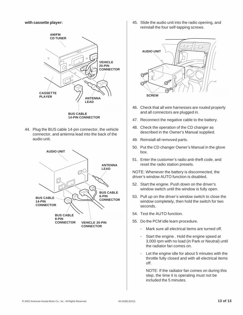
with cassette player:
2626051K
AM/FMCD TUNER
BUS CABLE14-PIN CONNECTOR
VEHICLE20-PINCONNECTOR
ANTENNALEAD
CASSETTEPLAYER
44. Plug the BUS cable 14-pin connector, the vehicleconnector, and antenna lead into the back of theaudio unit.
46. Check that all wire harnesses are routed properlyand all connectors are plugged in.
47. Reconnect the negative cable to the battery.
48. Check the operation of the CD changer asdescribed in the Owner’s Manual supplied.
49. Reinstall all removed parts.
50. Put the CD changer Owner’s Manual in the glovebox.
51. Enter the customer’s radio anti-theft code, andreset the radio station presets.
NOTE: Whenever the battery is disconnected, thedriver’s window AUTO function is disabled.
52. Start the engine. Push down on the driver’swindow switch until the window is fully open.
53. Pull up on the driver’s window switch to close thewindow completely, then hold the switch for twoseconds.
54. Test the AUTO function.
55. Do the PCM idle learn procedure.
- Mark sure all electrical items are turned off.
- Start the engine . Hold the engine speed at3,000 rpm with no load (in Park or Neutral) untilthe radiator fan comes on.
- Let the engine idle for about 5 minutes with thethrottle fully closed and with all electrical itemsoff.
NOTE: If the radiator fan comes on during thisstep, the time it is operating must not beincluded the 5 minutes.
45. Slide the audio unit into the radio opening, andreinstall the four self-tapping screws.
2711111K
AUDIO UNIT
SCREW
2002030K
AUDIO UNIT
BUS CABLE14-PINCONNECTOR
VEHICLE 20-PINCONNECTOR
ANTENNALEAD
BUS CABLE8-PINCONNECTOR
BUS CABLE6-PINCONNECTOR