aied services technical inforiiao cy arlingtn · pdf fileaied services technical inforiiao cy...
TRANSCRIPT

UNCLASSIFIED
AD 282 083
AIED SERVICES TECHNICAL INFORIIAO CYARLINGTN HALL STATIONAILI, 12, VIRINIA
UNCLASSIFIED
NOTICI: When govezizint or other drawings, speci -
fications or other data are used for any purposeother than in connection with a definitely relatedgovernment procurmuit operation., the U. S.Governiment thereby incurs no responsibility, nor anyobligation mhatsoever; and the fact that the Govern-meit my have forzalated, furnished, or in az viysupplied the said drawings, specifioations, or otherdata is not to be regarded by implication or other-vise as in any i er licensing the holder or anyother person or corporation, or conveying amy rihtsor permission to - ptre use or sell anypatented invention that may, in a v y be relaed,threto.
V1V
Ri
T I A
-j ' --_-
II 1TS

BestAvailable
Copy

irst Annual Report
WOn the Propagation ofLVLP Waves in Solids"
S- Dr. Wolfram Bitterlioh
Contract no. 61(052)-490 December 1961
J /

* - SummaryIntroduction2
I. Theoretical section1,1 Theoretical Vouridations of the Propagation of
VI.F Waves -I1#2 Derivation of the Poynting Vector of an Eleo- 1
trio-and Magnetic Dipole 11.3 Magnetic Moment of an Air-core Coil 141,4 The Design of Transistor Power Stages 15
2. Experimental Section,2.1 Preparatory-Work 1292 Equipment Sections Transmitter 19
Transmitter Amuplifier 20Transmitting Antennas 21The Receiver Amplifier 25The Receiving Antennas 28
2,3 Unetrground MeasurementsCalibration of the Receiver-unit 31Calibration of the ReceivingAntennas 32Propagation Measurements InteS.Gertraudi Mine 35i~ein the Schwss mine 3-6
in the Lafatsoh Kine 38Special Measurements 39
3* eologiosl-Section301 General Geological Survel 423,2 The Lafatsch Mine 423,3 The Schuss'line 43I3#4 the St. Gertraudi Mine 443,5 Detoumination of the Dielectric Constant of
look Samples 44

A theoretical and practical investigation of the -pro-pagation of electromagnetic waves of very low frequency,in conducting rook was carried o'it under considerationof L ( , and Qe. In the course of these investigationsit a-ppeared that the-decrease of the magvnetic fieldstrength strongly depends on the conductivity XC of therock. The experimental resul~ts were largely corroboratedby theoretical calculations. The paraeters 6 and/S haveeither been taken from tables or have been determined bysample measurements. As the majority of measurement.was conducted in mine Galleries It woo necessary to dove-lop special instruments for this purpose.
4<

---- -
Introd u-ction
Under contract-with the United States government
. .work on the VLP-research projsect was started in Decezrber
1960. The- investigations were directed towards a study
of the propagation of extremely long electromagnetic
waves in solid and liquid media,-the 1 equencies to be
used being in the range from a few cycles to below 100'k c .
An the scope of this program is rather wide, the target
for the firat year was limited to the study of the propa-
gation of a comparatively narrow low-frequency bend in
S •solids. n o rder to realize this project it became
necessary from the outset to organize two collaborator
groups: one group dealing with the mathematics and
theoretical physics involved in the problem and anotherteam engaging in the experimental and electronic work.The experimental team had as its objective the develop-
ment and construction of the necessary apparatus, as
transmitting and receiving equipment, special antennae
etc. This team was also designated to measure the field
strength of low frequency electromagnetic fields in rock.
These measurements were conducted in mine workings in the
vicinity of Innsbruck. Apart from this, it was required to
develop and construct special equipment for measuring the
electric data of mountain-building rock. The aim of the
theoretical team was the mathematical elaboration of
antenna problems of a fundamental nature. It was, for
instancet- of interest to determine whether electric or
magnetio dipoles would yield better renults in a con-
I "

I - ductirag medium. This program was extended by Osicula-
roo une-pce osdssin~g#/ and
su hppreendedua bytepAmricane lahitde tow thi~s
ofcienticre~sa program. sreot Ias neonly only hi
pOetwhi chaio requir d lrge mter expend~gitue
hepfor exten bi-th mermicin atoritnducto athof
J I an also deaeflyidb to Univ. Prof. Dr. t e n-nv
I tosur for ing his petermio to onutaa art ofxlgthoeatdprirint work *!tin the minesut of Scbwaeo te ns-
Ihanfalo grtefu o Mn rof D. Grin ier ndUnvPof.wr. for their vlu~e elp incthelundrtround Iao ,
an Stwoultdifd also likerte ito thnk all claoaos o hi
unceasing and, successful scientific work during-this yor.

Persons enJaed in work on the VL7 Project:
Project 8upervitOr and Contractors Dr. W. Bitterlioh.
Experimental team,0 GrObnerp graduate student
V. Gradl, techuicsl amsistant
0. Ilrs, laboratory- ossistatT. Blater, laboratory assistant
Theoretical team:D"1v. Prof. Dr. Gr~bner (Mathematios)
Univ. Prof. Dr. Oep (Theoretical Physics)
Dr. R. Hommel
B. Oberhammert Smlute student
b
-:- & 2*

j , . Theoretical Sectioninmm .u=3U lzmi~ B
!:I :he o r e t i c a I P o :U n- a t i o n is
of tbe Fro p a g at i on o f
V LF W a v e- a
Invest-igation of the propagation of electromagnetic
-waves of extremely large wavelength (VLF) in con-
ducting media.
In the sequel it is endeavoured to study the behavior
of the magnetic field in a medium characterized by
- - .the coiductivity , the dielectric constant E., and
the permeability/44 as described by the complete set
of MAXWELL's equations. First of all it is assumed
that the three material parameters be considered
constant, e, g., that they are independent of the
frequency. This implies a certain simplification
as regards the quantities c, and 'X, o as these usuallyexhibit a frequency dependence varying greatly from
one substance to another, as will be shown later. This
dependence can be demonstrated taking ice as an exam-ple; ... .
Prequency ohm - a
260 kc 2.05' 40.10 -4
4.6 c 153 1.10 - 4
As the experimental investigations were limited to
* relatively narrow frequency band, the above assump-
tion is reasonably Justified.

MAXWVELL's eqtiations are written down ao follows:
Vurf'4 1 ; d iv 0
ouri div -0
As has been explained above, 6 , /,a ando are
assume constant. By elimination of I the followingequ-ation resultst• v" mi. 9*,% H - (2)- ...
- f f " j . .e flt, there folloWs
AV2 + k A - 0
whe re C0 ~ 2(kc is a cor~plex quantity of the form k = ki + ik2 .
It is found to be
k112 a*')I OAA[444
In order to be in a position to solve equation (3)
in the usual manner and to. match our line of progress
to the special problem at hand, spherical coordinates
are introduced in the following:
x r. cosaj.sin 0 r < vo
Y r.sin I.sin :0 4 2-r.z r..coe of 0 4
The components of H remain unchanged: Hx, H y , and Hz.
If the Laplace operator is, Written in spherical coor-dinates-and then introduced in equation (3), itassumes the form
+ 0 (5)
Equation (5) is now solved by the usual method ot- seperating the vsa-ables: - A . .l(r). ? (f .........
i ; - , . . . . = :+. 4 .

EqAs I (6b)all pousn r 1 to eqatio or e obt, 1 2,..
thatonl the epoftide d on l on -raneedjiec_on aesrunts ti ecie yeito G)
ib ute +wa~n f(. sr~e~ eebeb h1rnfre i0oB5E' ifrnil*taiu
rucin wit

i~~~~~n ~ + ~ x."-3xcaxc(7)x
By conuverting it back to the variable r one obtains
The field of a dipole is described with sufficient accuracy-by the term of order 2 in the series expansion
r rf
iwhere kc iV the toplex quantity as specified above.
Fo an evauution. of the individual terms i.t isz neceesaryt~o mae th '.~o ealo By setting k = k,+ ik 2 one
.obtains by' sreaiahtforwred calculation the real solution
of ( 6 at- 3k
r r7)il
4 k1'r) (21cik 2 + 3k coo (t -to) + kjr') (8
This aolutiort can be matched to our special problem by a
au'4tablo Vbotode of the integration constants C and to
Relation (S) prevents a solution of the present problemiiofaz seit is correlated to the measuremients conductedto date,
Por the sake of completeness the solution of equation(2), the starting point of our investigationt is givenI blow,
- ~~~ IN t R R(r) Y2(fi)
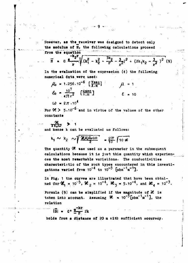
HlOWtVert as the Owreceiver was designed to detect onlythe moduluas of go, the following calculations proceedfrom the Oquu'tioll
Wt 7kIr 2 r (9
In the evaluationa of the expresion (4) the following6
numericali Cs*were- used:
- 256.,0-6 cjp.c
107 Aseec
For' e> 5.,0"and in virtqe of the valuee af the other
oonztants
and henoek can brealaeda followe:
The uantty was used as a parameter in the sulbsequentcalultionebecauase it Is 3~ust this quantity wtich experien-
ces he ostremarkable vairiations. The conduativitieschaectrieioof the rock types encountered in this investi-gatins arid. rnm 10-to03 cm'1j
I In Pig. I tho-curves are illust~rated that have been obtai-ned 1-or' 3= 10 -t - 5-10o , andW = 10-3.
Formula (9) can be smlfeiftemagnitude of JY istaken into account. Asumn 1o'E[ohmIm-1 J, therelation
C'L-.2k
holds from a diwtance of 2,0 a %itb sufficienit accuracy.

1 71
4111
KJ- -- --- -
-S 0640

1 0
-+ + "10- -~
1,2 D e r i v a t i o n o t h e P o y n i n g
SVector of an! Ele ctria and
Ma g n e t i o D i p o 1 e
For extremely long electromagnetic waves the antenna forms
that are practically realizable are described with suffi-cient accuracy by the equations of the elementary Hertziandipole which, in dependence ion the antenna current, read
ais follows:a
Electric dipole:
B 2 Jdl I + ik* cOSl e-ikr
1 J.dl I ik* .*2
' V-5 4,-r M + 7- - ) sintT.&±k*rr r
M Jrd (, + ik*) sin (611.ik*r
Magnetic dipole:
+ /+o+P I~ ~~ ik* _)+ ..-+.. .Rr + .- ) cosk911e-W
o4ca I ik* n *.e-ik r i
H+ I 7 7__ + -)
Abandoning the possibility of inoreasing the antenna
length dl or the antenna cross section F, the field
strength realizable for a given frequency and distanceis uniquely a function of the antenna current J which is,
however, limited
(a) in the electric dipolo: by the capacity attached
at the end of the dipole and the antenna voltage,
'-A-

i7
__(h) in the magnetic d4ipolet by the conductor lossea
in the frame and the transmitter power.
Moreover, the decision, -What-kind of dipole vadlation
ie to be used with very long waves, depends on
(1) the radiation conditions in the vacuum(2).the propagation conditions in the conducting medium
(3) which limitations, inherent to the apparatus and
mentioned in item-(a) and (b), cen most easily'be
overcome.
(1) Radiation rconditions in the vacuum:
It is known that the freouency characteristic of the
radiation resistance of a nagnetic dipole does not favor
the emission of long waves., However, in this investigation
stress was laid primerily on a maximum output of electri:..
S - energy and not on a high eantenna efficiency. From this
viewooint-the magnetic-tyoe antenna is more favorable than
the capacitive dipole, because it permits the generation
'of higher field strengths, alLhough at a lowe. efficiency.
If the electric field strength of a capacitive dipole
with a length of 8 %, having a distributed c07pacity of
100 oP is calculated in a direction perpendicular to the
dipole axis at'a distance of 10 km, it attains the
following value, the antenna voltoge being 1000 V and the
freouency 10 000 c:
Eq. o 1 -7, 212 04 T
686.10 12 TV 101
~iLJ L~ .58.10
II

Under otherwise equal condItions, a mugnetic dipoleas, has&e been used in the ne-asur-ment-t (cross section
0.8 m2 conductor resistance 0. ohm, 40,.turns) opera
ted at a power level of 80 watts auptliei a field
tren 1.25.10..10-40.23T.10 (1 + 2 10)Em10 3-0.,Q
"5 '6. 10_ LV/ilit Proceeds from these values that it i:,. more- easilyrealizable to prod'ace appreciable field strengtha by
means of a mianetic dipolle than by an electric one, in
spite of the l~ow efficiency of -the former.
(2) Propagation conditions Tor the energy flux In a con-4ucting medi un,~
As the experimental investigttione were conducted under-ground, the cornductivity of the surrounding rock had to betaken into account. ?or the sake of simplicity, the prac-tical arrangement is simplified in the theo-retical treat-
ment:. it was asumed that an empty sphere with radiusr
j(.- 1, 2wC0) is empbedded in a uniform conducting mate-
rial; the dipole Is located at the center of the sphere..If both the electvic and magnetic dipole are takcen toradiate without loss, so that the power supplied to thenis completely transformed into radiation energy and if the
electric and 'magnetic dipole are supplied with N watts, wehave on the surface of the sphere (r r )- .- ta
o) 1e - Q, hais
Re Ep Re Re
Re 1 -e -
Re 0- e,, -v m e-
r 0 ro /4/io 167r
r r r- r

-13.
If the magn etic and electric dipole are-to radiate the
same amount of energy, the ratio of the dipole moments
must be
me Me 2 Re k Jm kr-.- - 2 ro - - - . ... 2
We will now investigate the energy density of both dipoles
T - in the lone-range field:
R me me J- k*2 e-(k* C- *)r
Re "*)r sini .
Hence the ratio of the ,electric and magnetic energy
densityme I Re Jk* Re k* Z2
tiMm 0 Jm 2Mm- m- = -no TC 41M z ""
But k*2 6)2 ~ ~ ) k2~
Z "0 1- ZO
and, u *
and hence we have
e r J kU* Re kou* Z2/U 2
• 22r, .
.o (1/u* 2 )
It can be easily taken fromthii relas zrtha -t ..th.'-'
IU

14.
increasing wavelength, the value of (r/ 0 )2 dimini-
shes and hence the magnetic dipole becomes the more
favorable tranemitting antenna.
At a frequency of 10 kc, a sphere diameter of I m and
a conductivity of 10 4 the ratio Ce/ (5m 0.810-5
both the magnetic-and electric dipole radiating the same
energy.
These conaiderations show that the magnetic dipole exhibits
-.- tar more favorable properties than the electric one within
the frequency range in question.
1,3 Mag n e t i c M o m e n t o f an A i r-
core Coil.
It is desirable to have the magnetic moment as large as
possible for a given transmitter power. This implies that
according to the formula
MPnJ/40
the current, the turns number and the antenna cross section
should be made as large as possible. As, however, the
requirements of a high turns number and antenna crosssection are contradictory to a high antenna current (at
given transmitter power), it is worthwile to investigate
the question, which one of the design date has the cost
prominent influence on the magnetic moment. The followingequations hold:
1 n 2 ; R 2rn.
P *r 7T I 2rrn.

Aftvwauf- 15
where * specific resistance, q conduOtor crose section,1 a length of wire, r - coil radius.
Ftom these equations, the magnetic moment can be computed
as follows: 1 /
L2
As can be easily seen from this formula, it is favorable
to wind the given wire length in as few turns an possible.
This means, however, that an antenna with large cross
section perx, na better than one with many turns and a
small cross section. The transmitting antennas 8kIII
and SAIV were designed in compliance with these oonsi-
derations.
1,4 T h e D e s i g n o f T r a n s i s t o r i z e d
P o w-e r S t a ge s
The design of the new powerful transmitter was governed
by the following considerations: if a transmitter having
the limit impedance Rli0 is opened up and blocked perio-
dically by a sinusoidal voltage in class C operation, the
internal resistance averaged over one full period is a
function of the angle of flow of collector currents
Ri R lin-fl.
where
f- in2ec1 - ooe))
*and
.. - angle o flow of collector current.
The poWe2- supplied by the transistor is calculated from

// U R-
- 16 -
S0 lila (I + i-~-(Ra Ai.3 +1 ,1 1 1.
where Uo battery voltage, Ra load impedance.01
-The maximum output _power depend.a -bn the angle-of flow ofcollector current -and on the ratio Ra /Rlim. It can 'berepresented in a diagram from which can be taken the
specific load impedance required for maximum output power
-at a given current, The efficiency is given by21I fl 2I1
To- f...I Rail/Rlm
where 1, 1 sine - coaE@
The available power N,.,, is, as is the case for the efficiency,
a function of the two parameters 05 and Ra /Rlim, both of: ,which can be chosen at liberty as design p rameters. As flo
and q depend on these parameters in a different manner,
it is impossible to design simultaneously for optimumefficiency and maximum power output. Only one of these
objectives is realizable at one time. At maximum output
power U 2 fSNNi opt = -- i
the efficiency is low, because for equal generator and
load impedance it is natural that a large portion of the
energy supplied is lost in the generator. If the design
is intended to give high power output it is worthwile to
investigate to what extent the maximum permissible oollec-
tor dissipation permits an optimum design. The normalized
* "collector dissipation is given by
i"

/ + ' : +;] - - .- .......... . . ,- c
7,., +'7t
0+ .) A
It adiaram is constructed from the correlated valuesof 9 and RUM, the constant collector dissipation being
used as parameter, in which the output power is plottedagainst the impedance ratio, the optimum adjustment oaxibe ed from the diagram, for a given oolleotor dual-
pation not to be exceeded.
. Owi g to the low limit impedance of transistors the vol-
-,tige gain is very hih, whence the following relationship
between the three limit values Q, Uo , and ICRAX results
Q (fo - 0.45fl1 uo lCaa
IIf the power output is normalized to NI/I02U o, the relation
.& fo, ( o
holds. Hence it is only necessary to determine the mazi-
mum output power in dependence on Q: assuming an arbitrary
value of Q, (fo - 0.45f,) in determined, whence the angle
of flow of collector ourrent, f., and the normalized out-
put power are derived suocessively, The optimum output
power is obtained, if the oollector dissipation, the Maxi-
mum collector current and the maximum collector voltae
are correlated as folowas
Q = O. 10 cmaxU
In the next stage of work investigations are planned Inwhich the transistor is driven by rectangular pulses.
I.-
I - - -

2. Exper'imental section
291 P re9pa r at ory aor k
The -exp~erimentol work envisaged within 11he VUP project:,i mostly in a frequency range which to date has senvery few measurements of a comparable nature. -Hence itwas endeavoured to use higher frequencies (below 200 ko),in particular in the early stages of the work.-Thisenabled us to include-Zindings in our comparison whichwere, ;.or instance, obtained by FRITSCH in the Schwazmine about tensyears ago. PRITBOM made measuremenitsin the short- and long range region to bridg'e under-ground distance$ as large as possible. He also had in
mind the utilization of his experimients fo-r 'the establish--merit of communlcation with miners in distress. FRITSCHhad to be very-careful to avoid disturbing influencesfrom rail ins tallations, pressure conduits or electricalcables which, by guiding electromagnetic waves, give riseto unfoundedly large propagation distances. 'The recep-tion of the Innsbruck radio transmitter (570 kc) was alsosignificantly better in mine workings with rail installa-
tions than in such as had no metallic connection with thesurface.
For our preliminary experiments we constructed a smallbattery powered vacuum tube transmitter whioh radiatedat a power of almost 1 watt at a frequency of 200 ko.A 20 cm long ferrite rod was chosen as a transmittingantenna which simultaneously carried the PA-ciWrtuit ofthe transmitter (fig. 2,0 Pig. 1).
-------- ~-z-- comeri.~potebe~ ~ai4 ot~r Radion. £22!) was__
used as a transistor receiVer, after having been modified

1,
S
t'I~
_ _ -'at~.
*1~~
*(*4 ahr., ci
0'I I
* S * *-~
4I A0 S
SI 0
I,0 0
H I~~1I~L~IH
________ I.
ieI&
s~. 1-4
44 V
______

p~ A'
,~.d,*ne Pv2 F 3 2,2
ig. 2.1

for this special purpose (Fig. 2,2). The control vol-
tage has been lead out to terminals where it is measured
by means of a translator d.c. voltmeter (S-meter) (Fig.
2#3). Although the receiving unit (Fig. V) had not been
calibrated in field strength units, it was nevertheless
possible to estimate the reoeption results in a -qalitat-
tive and quantitative manner. The attained propagationdistances were moderate owing to the small transmitterpower available.
,-The purpose of these experiments was to obtain a generalsurvey of the directional characteristics of ferrite
antennas. $everal informative. measuremAnte -were carriedout above ground on level terrain aw'well as in under-
ground locations. The decrease of field strength asdepending on the distance and the directional character-
istics was measured both with horisontal and verticalantenna poeition A depend-ence upon- the. degree of soil
moisture could also be established. As for the remainder
the same results were found which are discussed below
in the section on the transmitting antenna:SAIIl.
Apart from this# initial measurements of the field strengthof the Innsbruck radio transmitter were also carried out.
The field could b- asoertained to large depths in the
main gallery.
2,2 X q u i p a e n t 8 ec t i o n
IL? Measurinha eguipment
2ransmitter:The transmitter that has hitherto been used for theaeasurements -coneisted of the folowing parts- batteries,

-20-
RC-generators, transmitter amplifier, exchangeable trans-mitting antenna, support for the antenna.
The individual sections were connected after arrival at
the site by means of leads. Thus the transmitter was
prepared- ft- ~ration '(Vg. ITO.
A transistor, type Levell TG150M RC-generator was used
as oscillator, supplying a maximum output voltage of 2.5 V,
which could be attenuated by steps of 20db each. It oper-
ated in a frequency range from 1.5 o to 15C kc. The a.c.voltage supplied by this generator was used to drive
-r eatly - he
Transmitter amplifier:
This amplifier has been developed in our laboratory andis designed as a 20 watt low frequency amplifier; it is
mounted with TF78, 3 x TP60/30 transistors (Fig. 2,4).Power in supplied from two lead accumulators 6V/Ah.
The amplifier draws 3.5 A at full operation, which is
equivalen 'to an efficiency of 50%. The capacity of the
batteries allows a two-hour operation.
The transmitter amplifier has been designed such as to
permit the connection to a symmetrical or an unsymmetri-oal load. The power transformer is out in or out as
required by the mode of operation.
The mximum power of 20 watts supplied by the transmitter
has been used to generate a powerful magnetic field whiobis radiated by the antennas.
i "j

Iw
1LM
'ON
1PC
ii

-21-
Transmitting antennas;"To date, four different types of antenna have been
built (SAI to SAIV). Initially a procedure was chosen
by which a coil with a very high inductance was wound
on an iron core, In order to eliminate the disturbing
influence of the reactance of the coil, theinctvy
L was parallel-connected to a capacity C to constitute
a parallel resonant circuit which was tuned to the oper-
sting frequency. This measure simultaneously broughttwo more advantages: first, the porer transformer and
the losses generated therein could be eliminated by asymmetrical design of the ant-enna, because it was fed
through two taps located symmetrically about the center(in which instance care had to be taken to obtain the
correct impedance). Secondly, the current through thecoil was increased as in every resonant circuit (Fig. 2,5).
Fig. 2,5
For every parallel-resonantcircuit there holds the
relation that the partial currents JL and J0 are lar-
ger by the ratio expressed by Q, the figure of merit
of the circuit,than the total current J passing through
the circuit.

Th pho -h~to o ewe n aocriga
tpha e t ofn 90el beteenad by ecticurrn t.
TOe cAergy required i,, cover the radiation and eddycurrent loosesa In tie rocb ca b re&&de-d 64 b0einnegligibly small.
On the basis of these oonsiderattons it was possibleto design the antenna in such a way as to utilize tiletotal energy supp-lied by the transmitter to compensatefor the ohmic losses in the aimtenna onl2Iy.
Desigiq data of the transmittng antennas _SAI and SAL I -
(Fig. III).
Transmitting anrtenna ItIron rod length; 100 cm, sheet material IVIron cross section; 6 cm2
Turns number: 2 x 96 turns# conductor;,,2 mm diam.
copperOhmic resistance: 185 m4l
Inductivity: 3.2 mHTaps at + 25 turne, sym-metrical about the center
Transmitting antenna II;Iron rod length: 100-cmIron crone section; 3.5 cm 2
Turns number: 2 x 450 turns., conductors 0.75 mim diam.
copperOhmic resistances 3.1 ohmsInductivitys 80 mETaps at + 25 turns, symmetrical about the center
It appeared, however, that in practical operation these
antenna forms- dill -not perform satis-factorily, beoaupeth

effective surface woo too-small and the losses ini theironi core were too large, Por-thts reason, henceforthother~ measures were adopted in the development of thetrans~mitting antenna SAulT. The Iron core wes- removed;
--- L in9, or omprnensate for the resulting 1Qse :In indqcti-vity, the diameter of the coil was increased to such anextent as to keep within the dimensions of the mine wor-kings. This method afforded the following remarkable ad--vantage:t
* The magnetic field in the axis of an air-core coil whichmay be regarded as an n-fold circular loop, cam be calqu-lated In the vicinity of the transmitting coil from thefollowing formula:
The turns number was chosen as large as was pexmitted bythe ohmic resistance determining the figure of merit ofthe circuit and the resonant resistance. Anotber, in noway less significant limit for the turns numbex was thecopper weight, because in consideration of the requiredlow resistance and 'the maximum permissible oureat thecrose section could not be chosen too small. Il ii vorthnoting that the copper weight Of SAWY is more than 1-7 kgand that the complete antenna, weighing 20 4,j cannoteasily be transporteod In narrow mines. As has lsen shownby theoretical investigations it Is more convexient towind a coil from very few turns) but with a diameteras large to possible fort given wire length i-n-ozdsrto obtain a ma4mum magne-tic moment.
The transmitting antennae. UI and BAIT were 'Willt scoor-ding~~~~~~~ toa tkiecnisain.tei orit oa uauual n

" S -vXitA out *ttb te AIZI.
t in Iron tore is wb*AV* it is posaLbl to determinethe exp*Aental onditions uniqaely by stating the
. .treq~ne7 si% the o rrent J throughb the tranexttingaix-l The- reavlton of tb* eo-i was, u before, =W#i
to vanishx by R*0n* of * series oonztottor with a oo4-dener *f a ospaoity suitable tor the fretueny ued irnthe exporimenas. The resonant resistance R. is ldeti-
051 to the ohnia resittenoe of the- coil aid kan be kept,itbin amull li.tito by increaing the conductor crossection in order to Obt1 n large curents J. tf tbv
tranamitter power U and the resonant renitace Rgiven, the current is calculpted from J qoi7;'2In crder lo match this tranazitting antenna to the
aplifitr output a power trantfcrmer of nuituble dimen-mns is required. The current in the antenna circuit"
Is being measured with a Philips instrument of the type
P 81700/0). In order to prevent a reduction of thefigre of merit of this circuit by a too low L ratio
at the ivetn low frequencies it wa necessary to Increase
For the coil desi nv used I, its owlallated. frou
wheip k form faetor, depezding ott c/b
i '- turna number

1.Design data of the" ante16-nna SAIII (F'i&. II).
Diameter D = 98 cm
I I inding width b =-2 eraWinding height o. * 1 ci
Conductor' cross kection: 1.2 imm diem. copperlncuctivity; 5 infP 'Ohmic reaistanlce, 1.1 ohms
T~o dtqt, the invettigations have beeni limnited to dipol~earitennas., The qutestion., whether antenna formsa of higherOrder', as quadripoles, for ixistarxce, will provid-e betterreasqt.,., must be decided by further theoretical studies.
All antennas of a dipole character possess a directionialchaLrcteristic dependinG on the angle It appearedfrom the me~iourements that in the direction of' the dipoleaxle the field strengtb is tvyioe that perpendicular to It.This (Y&-dependence has been establihhed by separate mea-surementt. As regards the ireasuring techniqae, difficul-ties were encountered in adusting the transfiitting antennain the mine In ouch a way as to ensure coincidence of itsaxis with the strai~ht line connecting tr..nsmitter and
j--. receiver. When mine mape were available thin directioncou~ld be found by L-earis of ft compass., If this was u-otthe case it had to be found empirically. It can be seenfrom the antenna characteristic, however, that an error
in the directionul adjusten~t of + 20 0ceases an errorin the field s-trength of no more than5.
T ~ The receiver &mplifier:A)Por detecting the magnetic field radiated by the trans-sitting antenna an 8-ttae selective amplifier equippedwith~ t-ranuistore 1/AC1O?, 4/0071, aaid 3/0C72 was used.
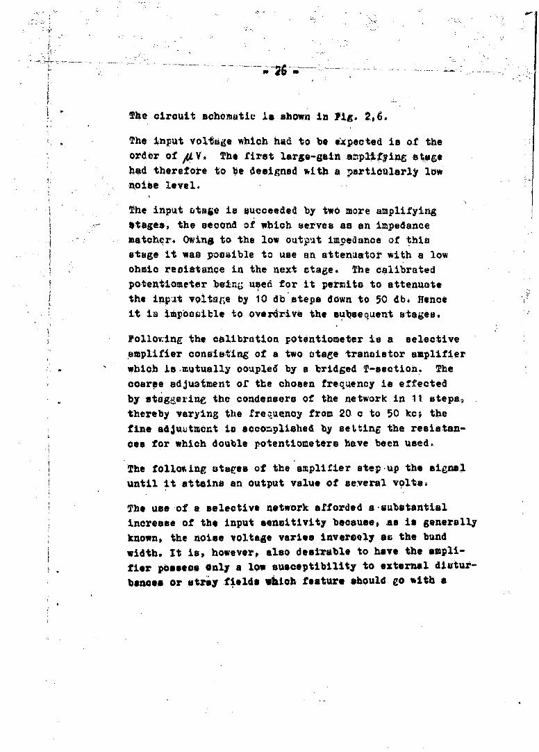
The circuit schematie I& shown in Fig. 206.
The input voltage which had to be expected is of theorder of # VY. The first lar& -ain M amp~n stag@
hod there! oke to be designed with a particularly lownoise level.
The input soto~e is suacceeded by two more amplifyingotagesa, the second of which serves as an imped-ancematcher. Owing to the low outpu.t imp~edance: of this
$ stage it wag poesible to u~se an attenuzator with a lowohmic recittance in the next ctage. The calibratedpotentiometer being u~sed for it permits to attenuatethe Inpat vQltage by 10 db steps down to 50 db. Henceit is itpoco~ible to overdrive the sulzoeue'nt stages.
boling the calibration potentiometer is a selectiveamplifier consistinag of a two otage transistor amplifierwhich ii .mutually ootzpled by a bridged T-section. Thecourse adjustment of the chosen frequaency is effectedby stagee'izi the condensers of the network in 11. steps)2thereby varying the frequency from 20.c to 50 kc; thefine adjuktment io accomplished by setting the resistan-cos for which double potentiometers have been used.
The follo~inp, stees of the amplifier step-up t he signaluntil it attains an output value of several volts4
The use of a selective network afforded a-substanti-alincrease of tb o input sensitivity because# as is generallyknown, the noise voltage varies invereely as the bundwidth. It is, however, also desi-able to have the ampli-fier possess Only a low susceptibility to external diartur-
bances or striy fields which feature should e~o with a

*O
(4 Y
'a.k
it01 L.

404
$ 64 4 t '

-27-
reduction or the noise level, A new receiver model is
now being constructed in which it is at'Ted to attain,
an enhancement of selectivity and, at the aame. tim., on
increase in senisitivity.-
Desig. data of the receiver amplifier
Input sensitivity: 2ALV
Zignal-to-noise ratio: 30 db unGain: 113 ± 3 db in the entire fre.jue-y range, ad-
3uctable in ste-ps of 10 db ea-chOper'ating voltage: 3 x 4.5 V flashlight batteries
stabilized by two :Zener diod&es.-
Input impedance-. 10 kLOutput iimoedence; B0O&AIFrequency range: 20 c - 50 kc, su-bdivid-ed.,1tdt .1,1
ranges.,Band Width: 0.4 (at 10 kc)
An internal view of the amplifier is shown in Fig. VI.
Theoverall gain of the amplifier is in the region of
4.5 - 4.7? 10 - Originally it depended markedly on thelevel of the siuplly voltage which was taken from three
4 ~ series.-conr.ected flashlight batteries. This disturbingeftect was eliminated by stabilizing the operating voltage
of the first six stages by means of two Zener diodes OAZ3.
The residual fluctuations are now lese than + 0.2 V.
The output voltage is constant to within 3 db over the
entire ranee, as can be seen from the frequency -charac-
teristic. The residual error is eliminated by a control
procedure which consists in checking on-the amplification
in the laboratory every time one series of measurements
in the mines had been completed. This was done at exactly
* the sme frequencies as were used in the field.

The output ui~gnal of the receiver amplifier is fedinto the oscilloscope Tectronics type 321 for measure-
A .sent. This affor.e~ a measurement of the amplitude of
the signal and of its frejuenoy together with an et-
mate of eventual diaorbanoes.
* InItially the oscilloscope could not be used for these* measurements, because the receiving antenna which had
been placed at a distance of only two meters, from the
osci.lloscope picoked up the entire utray field from; it.111gh voltage ir, the oticilloscoe is produced by two
blocking oscillotore operating at fr'eq-4encies of 2 koand 20 Icc which radiate a9 powerful frequency mixture
*rich in harmoncoc, Hence it was required to place the
ouciJlioscope into a casing of 1 mm sheet iron, to shield
the battery leads very carefully and to filter the batteryvoltage aft er en-tering the casing. In oider to en~oare
longer operation of the oocilloscipet power was taken
from two separatc 6 V accumulators wkilch had also to be
placed in a casing.
F~or some seaaiireimenta, especially at small ranges or in
difficult locatione a traneistor millivoitmeter (Levell
T12B) was used to repluce the oscilloscope. In Fig. IV
the complete receiving equipnent is ahown.
The receivibig antennas
Great difficulties were encountered in the construction
of the receiving equipment when it came 'to the designand the construction of the receiving antennas (termed.
EA..) As has been shown in the theore tical oectionthe design must aim at balancing in the moot favoravle

-29-
These factors arci inductivity, effective crome section,
spuarious winding capacttnces and the obmic resistance
of tie coniduotor wire.A large inductivity car, either bew chieved' through a ferroue-cored coil with only a fewtu~rns, or by an air-core solenoid with many turns anid
a. az~dameter (c'ross ae-ation). -h rbl tat had
to be-solved now was to find the most efficient design
by means of theoretical evaluations andi practical experi-metts
Design data ol' the receiving antenna ~A:it oon-Eisiedof a ferrite rod on' which two series-coniiected cro'esed
coils with a very high in ivt were wound.
Techntical datia of the antenna EAI:Length of tf:eo ferrite rod: L =47.5 cm
Di~atreter/croas section: d/F =1.5 cm/1.77 cb.
Ohmic resistance.: 135 ohmsInductivity: L =0.8 H ( =1000)
Receiver ineerte-d at the mtid-point of the winding.(See Fig. 2,8 just below).
Fig. 2'
In Fig. VII is shown the antenna3 with the static ohield
removed#
The antenna was connected to a variable capacitor to
icw, a parallel resopnant circuit. Thuu it could be
ajldlsI 'to the frequeny of the tranbmitted signal.

Th e wincing. iv tapped at the center, where the receiver
input is coneted. The figure of mi~erit of the resconantcircuit -is relatively highs owing to -the large HC-ratio,Iand the low capaity of the winding, The voltage gainresulting frwm this is give,. by the factor Q-10. Owing
to the smail geom~etrical adamenaons the antenna can
easily be shielded against electric fields by neans of
an aluminum foi. Hence it is only little slace-ptibl-eto dioturbing fields, thus permitting the utilization of
the full sensitivity of the am~plifier.
An increase of the senoitivityg the f~gure of merit
remaiting constant at the same time, can be aoiieved
by an increase in the cross section of the iron core.Another method would consist in placihr several antennaeSof the EAI typ6e side b ' side and to series-coni:ect the'-u.Studies in this direction are being made.
The receiving antennas EAlI and EAIII were built accor-* ding to a prifciple differin~g from that of the ferrite
* antenna.
The antenna EAII consisted of a ulender toroidal sole-noid. its electrical performance data were very unfavo.-
rable so that it wee' not -used for furthor mibiisUreients.
Improvements were achieved in the debign of the antennaEA1II. It consists of a cylindrical coil with 1000 turns,
having a diameter of 45 cm. It was shown by undergroundmeasurernehts that the sensitivity of this antenna is
better-thah that Of BAI by a factor of 2 - 2.5 (at 10 kc),but that the directional sensitivity is worse. In spite
of this fact this type of antenna has proved to consti-tute the most favorable design. The receiver is connected

d
lato~ a t~p, the-Pojition of which isadetermined eprj oally. Simila~r to-the EAI this antenna is also tunable
step-tyre group of fixed capacitors.
Fig. IV shows the rec'eiving unit and conveys on impressionof the sixe aftd appearance of the EAIII antenna.
2f3 Un de rg rounad M esaa u rem2e nt a
Calibration of the receiver unit
The receiver equipment consists of severaJ. portable
units; it coiprises the:,interchangeable receivingantennas which are tunab le to the trainsmitted frequency,
the calibrated selective amnplifier and a battery powered* oscilloscope. To this is added the 'portable, metal
sheathed kit for three 6V/4.5Ai a'ccumulators~ which serve
* a-s a power supply for-the oscilloscope* because built-inbatteries would permit-operation for no more than about
one hour. The receivine antennas are interchangeable;
hence it can easily be arranged that different antenna
types are used duping one underground measurement, either
to find-the bebt' position of the antenna or to~ limit the
experimental error by means of repeating the measurementswith different antennas.
The receiving unit WeA~co'nsidered to perform satiesa-torily when it permitted the determination of the megne.tic field strength from the oltage measurements at theamplifier output T6. field stren the in our experi-ments were 'of the order 10O12[Wb/m ].From this value
* can easily be inferred that for' alibration operations

I0...... . . - tl -
a location had-to be found where disturbing magneticfields could be kept to a minimum. AA detailed study
of cOmmercially available Faraday oses has shown that
none of them meets the rigorous requirements as con-
cerns magnetic shielding against low-frequency fields.From thease-considerations it appeared most convenient
to conduct the necessary calibration measurementsunderground where conditions are naturally the same as-
for the actual measurements.
The calibration consisted in generating a magnetic field
of known magnitude, inserting the receiving antenna intothis field and measuring the output voltage of the recel-
ver. The values of the measured voltage thus obtainedwere then converted back to the input voltage; this vol- !tage was plotted against the known field strengths. The
transmit1-g antenna was directly used for the generation
bf the calibration magnetic field. According to theformula
B .... J R 2/2(R2 +the desired field strength which was measured at a distance
of about 10 m from the transmitting antenna could easily
be adjusted by a variation of the current J. Some diffi-
culties were created, however, by the necessity to elimi-
nate undesired eWfeots, as.,, for instance, the influenceof stray electrostatic fields.
Calibration of the receiving antennas EAI and EAIII
(Fig. 2,9)Frequency 10 kc, r = 1.2 si, transmitting antenna SAII1.Parametric variation Of J (mA).

71
9%
'U, ~i.'2
I
- 2
.2 S
0
S
p St

49 88,5 6 171.-3 48 1 60, 6!820 r36 10 "
;I: 20 145-•5 70
10 19.2 1-0- ?o6 3 5
2 4,,5 7 :-: 2 1.5.6 7I
: 1 .2.15 3.5' 1 7.2 3.5' ;0.51 0 M9 1"78 .0.51 4.05 I °78
: 0.12 1.01 0.42•51 "10 178
212 -. 5 .10'12.1
Przoilptation measuremnts
After thea L io1brat~ou had been suoeetu11y ompletedo
the quaztttiVer propagation measurements of eleetro-magnetic waves in rook could be strted.
Interest in these measurements we* ceneered about acheck on the qredlotions offered by theo'*etioel oonal-d erattone ooACoexig the decrease 0of field strength
over distance In took with a varying degree of oonduo-tvityr. 5The',est friqueaby was Initially settled 'at
10 ko. This ohoe was justified b~y the imittionsinherent to the transistor amplifier , because, owing
to eoffteon y considerations, the available powertransistore 4id not permit the uee of higher f~roquenoies.
On the other heari, the design of the transmiting~ antenne,
• Imp"~l a lower 1intt on the &esouring f~requenoy whichIs about 2 ko. It will be the aln of further Investi-
IT
Ir

Iptiou~ to roach lovea&r values by a systematic reductionOf the freqmonoY.O
31n the sequel we will select from the numerous fieldstrength measurem~nts that have been made in threedifferent mines,, four relpreventative experiments, -andoffer a taie -i~au. of them.-
The field locatI.,ns were selected on the basis of mine*maps and inspection tours. They were considered parti-f ~ cularly favorable' if electrical or fluid conduits or
rails wore absent in the workings.- Secondly It was deai-rable, to% have no large cavities in the immediate neighbor-hood of the transmitter and in particular not near the
straight line connecting transmitter and receiver; still.the system should be of sufficient extension asa to permitmeasurements at intervals of about 20 m.- Uare was also
taken to obtain at least an approximate picture of thegeological structure of the rook along the workings con- -
neoting the mneasurement cocations., Yortunately no greatdifficulties arose in finding such locations in the minesInspected for that purpose.
After the transmitter had been transported to the soeo-ted location and the orientation of 'the ant~nna hadbeen completed with the help of mine na pa and a compass,the receive r w~s carried to the Individual measuringl6oations; the antenna used in one particular experi-went was adjusted to give maximum field strength. Sub-aequent to this the voltage oo-urring at the amplifieroutput was measured.' Depending on variations in theambient conditions in the rocks distances reaching to220 m could be, bridged.

Curves 1 throu&U -4 in Fig. 2910 illustrate the resat4of "the ezperizer.2,a. n-t can easily be discerned that the
individual series of measurements in the diagr~ams deviate
stronrgly, from o~ie, another. This may be explained by
variitions- in theI , parameters 6and Q.4-was deter-jmined# as- has, been. explained in ,the theoretioa& section
(11) from tables and through measurements, and. further
digression on this problem does not fall within the scope
of this section. Purther considerations wil,.l be conse-
crated-to a discussion of the influence of the conduc-
tivity parameter only.
Measurements in the St. Gertra di mine -(Gro~kogl)
min ma o.
The transmitter was, placed in locationeEVII and EIX,
the measuring frequency was 10 kc, the anten-na current
1.25 A, the'antenna used was SkIII.
* Results:
Measuring diet. UO UeIII JI B ,location m
1 J 23 00 500 650 200.77
2 / $B 95 150 185 70 0,23
3 / 56 32 60 60 28 0.09
4 /75 18 30 32 14 0.045
5 /95 9.9 18 17 8 .21 0.026
6 / 11 5.6 8.5 9.3 3.8 0.012
8 /15i - 5.6 - 2.5 0.0081
9 /1.85 -1.9 - 0.85 0.0027
10 /1,25- 0.8 0.- 0.0011

-. --. ",'
the values t'Siven for the modulus' of 'the magnetic fieldatregaSt are plotted in Pis. 2,10. Every series of valueshas suboeqqently been converted to, the extrapolated;_. -fieldstrength at 20 m dstance in order to afford a eatisfac-
Atory oompaeon of the curves., Two theoretical curves
have been added whiob have been' oaoulated for a oonduo-
-. tivity 9C of 10-3 and 10 . 4 hmn]. ; -without exoeption,
the experimental ourveso keep within the ltm-ts drawn by
the theoretioal curves.-
A behavior similar to that of curve no. I Is shown by the
. series -f measurements reoordeO in the Sohwas mine. T e .
conductivity there in of the same, order and the rock i. .
A -~_the ,two locations Is also of the same nature.
Jesreenta n he ohwa minej mine mai no. 2.
The transmitter was placed in locution no. 4; the measu-
ring frequency was 10 ko, the antenna current 1.25 A, the
I *antenna used was SAIII
Results:
measuring dist. U61 UOII 1131 1311z 191location m
- 20---- / 25 128 520 225 250 0.630 / 47 30 120 55 56 0.14a/60 16 60 28 28 0. 7
b / 78 85 50 14.5 14 0.035
a / 98 4.5 15.6 7.2 7.2 0.018
d / 115 2.8 9 4.4 .4.1 0,0105e 133 1.9 5.6 - 2.9 2.6 0.0068
f / 150 1.27 3.15 1.5 1.1 0.0032
6 / 186 0.76 1.9 1.1 0.85 0.0025h 1 196 1.27 0.5 0.0012
"" ' ;' - ... . .. -- - - - == ' " ' " " " "- --

JJ
Te0srmdt'ac- pltte- -h. i - -;
*bAA r-'10,.
Lait The Dim~ieen~ 0
e, otia ton ~
-- -)
Tft~
if an ~a~~y ~ raced b'd~ 1a -d "tbTi6e 'in ,the
1K10 1 reahou U ;a ',- falai:U:
4a", iv i e ,,~~esdwt oe h nle ce o~~the~ ore eot~ Le plAl dicrnbe bb-ua te fo-
JdutiiW s 1iee t ou nties at in The' Schwaz mine.
It is whoeth nting hat th i t 'otverse iw I vrag
,,veTh e Pentir~eft voBlaetlu differinge becaus th ete-
9&&fo -rook samplesI.
-esurements in'the Lafatsoh mine, (series n o. I).
Ae transmitter was placed in location II, the measuring* frequency ws 10 ko, the antenna current 1.25 A, the
-antenna used ws SUNIT.

Revolts (I
Soc~on Mi -
./20 i-I
-/ 31 125 600 250 280 0.37P/ 52 31.8 127- 57 57 0 48U2
so 80 9.2, 38 1,5.5 17.5 0.0234/105, 3.6 16-.3 5.7 750.0086E/130 1.. 7.9 2.8 0.0043
.- < .. /161 11 3.8 . 1.7 0.0023~ 26 0.3 2.2 0.4 1 0. 00086
"Me t r in the Lafatsch._nine,3(series nof. 1.
The transtaitter Was placed in location II, the measuring-
frequency woa 10 kcO the antenna current 1,'25 A, th-e-~antenna used wau SAIIl.
k~easuring dit. Ue UeI JB )BIulocation m
A C / 20. 620 2000 1400 1000 1~' / 43 28.5 -220 60 100 0.1
S7 71 8 .3 28.5 14 .13.5 0.014
E' 81 5.6 18.4 9.2 8.5 0.0093q /103 2.5 7.9 3.9 3.6 0.0037
In column no. 1 the receiver positions are enumerated andtheir distance from the transmitter is &iven. Columnsnos,. 2 eAn 3 contain the voltage~s measured when the re!-.ceiving antennae. SAI arid. SAul were uped; they are given..in jV9 converted back to the ampliftir',input,., Dy meansof-the iarmin Pig.- 2j-9 it is possible to derive the

Ii
2 'fO* -~
-a S. *.
7. - -
'.
V
'4*a. '4
7 . 4%
2
9'I
0
0
F~s'~1o
4 a
. I. 'U.
d

~399
field strength values from these voltage levelsgiven in columnn 4 and 5. In the last c6olumn thevalues averaged from col.umn& 4 &nd 5 are givenp Qxtra-,-polated to the field etreiigth'at 20'm distance'., This
field strength bos been assumed as unity.
Special MOeasurements
The work dezcribed to this point has absorbed the major
portion-of the availabl.e time, Howeverp efforts werealso made to itudy problems connected with the ,meas uring
apparatus. Of special Intereet was an exact'determina-.tion of the antenna chaxactexistic which bore speoial
weight in the theoretical wprk.
These measurements were conducted as follows: the trans-
mitter was pl aced in a large underground cavity in the
Sohwaz mine ("es-serachmitthalle"); the field strengthwas then measured at a distance. of 12 m in order to estab-,
liob its dependence on. the angle .The results areillustrated in Fig. 2,11. It can be clearly seen thatthe field strength in the direction of the axis of the
transmitting antenna is twice as large at a certain
distance than in a direction perpendicular. to the antenna
axis at the same distance..
Results:angle (0) _ orientation of B (0)
0 10
45 0.78 65$90 0.5 0
135 0.78 65180 1. 0225 0.78 60
270 0.5 0315 0.78 85360 1 0

pC
C~i

40 -
After these measurements had been coipeted the error
arising, from incorrect "dj.14 n t antenna was
closely investigated),. 4sing '4-he 8chz in e (ntenne map
no. 2) as field location. In order to obtain practi-
cally useful valuesl a distance Of -bout 50 m between
transmitter and receiver was chosen. The transmitter,
being placed in location no. 4, wap initially oriented
towards the first meacsuring location no. 0. The recei-
ver was then moved to other locations (a',,b',c'). The.
fiqld strength versus 6function as derived from these
measurements is plotted in Fig. 2,12 through an angle
of 600. The results have already been anticipated in
the section on transmitting antenna-s (2,2). For a mis-
orientation of about 20 the error does not exceed 5%.
Concluding, some remarks are appropriate concerning expe-
riments of a special nature, referring to the measuring
locartions in the mine maps nos. 1 and 2, which have not
be-en discussed as yet.
The first VIP measurements were condueted in the St.
Gertraudi mine, a frequency of 30 kc being used for
the experiments. The di4tanoes that bould be bridged-
were relatively small owing to the unfavorable antenna
design (SAI and SAII), the comparatively high frequency
used, and the low transmitter power (transmitter loca-.
tion SVIII, receiver location EVIII). Further measure-
ments which canvot be discussed in detail in this report
were carried out in the Schwsz mine. Their purpose was
to establish the influence of a body of gray copper
ore extending between the locations nos- 1 and 2
parallel to the main working (1 - 4).

-' 41 -
As a calibration facility an orefree distance of 160 m
length was chosen between the locations 5 and 6. At a
measuring frequency of 10 kc the field strength dropped
to 3%*of the original value. Maintaining the same expe-rimental conditions the field strength was then measuredbetween locations I and 2, the transmitter being placed
in 1 and the receiver in 2. Along this traverse thefield strength decreased to no more than 2%. This
remarkable divergence has been traced back to the jnflu-
enoe of a closed iron loop consisting of tubing in, the
working no. 2 and of rail installations in the workings1 and 8; it was not due to-th e0 action of the orebody.Depending on the orientation of the transmitting antenna,either parallel or perpendicular to the rails, the field
/ strength in location ro. 2 was large or small. Thesephenomena are still being investigated more closely.
Recently attempts were made to bridge larger distances
(to 300 m) using the same transmitter and a transmitting
frequency of 5 kc. Between locations 4 and 2, or 7- respect-
ively, definite field strength measurements could be made.
The results of these experiments will be presented in
a later report. It was substantiated beyond doubt that
the theoretical considerations predicting a less pronoun-
ced attenuation of low frequency electromagnetic waves
in conductive media, are correct.
-3. Geological-minewalogical Section
It has been explained already in Seco 2,3 that the expe-rimiental investigations were carried ouat in mine-s in theTyrol. The Schwaz mine, 26 km by road ea-st of Innsbruckand the St. (Gertraadi mine, 44 km by road east of Inns-bruck, are both situ~ated on the northern slope of the"Tuxe' Gebirge" (Tuxc mountains). - The Lafatsch mine, 47 kmby road nowth of nnsbrubk is ;situated in the "Iiinterau-,
*tall' (Rinterati va'tley) in t-be n.aighborbood of the so-orooo? the T3sca ziver ta thje "Karvwer elgebirgel (Karwendelnmourtains).
3v2 The L af at cah DIi n e
T'de mount;!4i'., ranve o. both sides of the outlet of theIHinterau vallty consist of triaszic oIL(sedimentaryrocIc)tpi;Jy of Hauiptdolor-4te, Tlnoping to 'the otmth.
Tfs orrua*' O. b ing, piused soth iii the vicinity ok thewine, whieh . fiu:-.tVer t~pritrea,, givez .*ioy to olderW~terst-ein .m.9nere and 1iaibler otrata north of6 -ZPzvalley. 'Th'i 11nt~rau valley is q * rmectcd to the ti~!ompe-..
u n~&wgorge tersinatiag at the village Vomp in-the inn bew~ y a wide pass, the tlUbez'sebhZ-11' In the
a:.ea of thir patc are loca--.ed -ammerous mediaeval orewsakingo. Abotit 4 kmT wezt of thece Norkihgp a develop-mcnt mine, the "Lafatsch mIne"l hau recently been op-ened
i~a the "KaEtc'n" a flat section of the llinterau valley atthe foot of the "Rieps", an eminence in the rid-ge nor-'ih1
-43.
of the Hinterau valley. This mine is worked for leadand zinc. ores occur as gilena (galenite, PbS) andzinoblende (ZnS.) -in pockes andstrong Ily .torn tabular-shaped orebodies,.
3,3 Th e S ch w az M insie
The Tuxer Leebirge, conas ing of ergillaceous slate6nd striking from west to east exhibits a structureoft a highly inthomogeneous- nature. On its northern'31ope isstuqted the medisaeval mining town Zchwaz.H-eavy folds. and overthrusts have. freqientlr resulted inen inveraQ! o, J the st:ratigraphio a, .umn. As'chaloraQk3 like phyllite and iaitriuive gneisse6 oontaining;11derite ave imostly superIMPOSed on recent argillaceoussl.ates which in~ their turn have 'been pu;shed over quartzphyllites (iliere numerous mines have formerly beenworked for i.:.on from siderite (FeCQ3 ) ores). The under-lying, more reoerit palaeozbic and triassic rocks are
moatly Sobh as dolomiter niw red sandstone and Partns: chstrata.
The Schwaz dolomite is the rock mostly interspersedtith ore occuwring as gray copper ore (tetrahedrite).This Schwis, tetrahedrit2 (CaMg(00 3)2) is composed pri-marily of oullux~u& COPPeN., SLIver, and mercury. Theziining system~ wr -;.ch has baen constantly extended sinceit was stacted in. 1409 has a total length at' 240 km.

-44-
3,4 T he S t. :Ger t r au i X i ne
Geological conditions in this area are comparable to
those prevailing in the -Schwa-z region.A Predominantstrata consist of new red sandstone and Schwaz dolo-_mite ("Geitraudi limestone"). Workable baryte (Ba SO 4and small qantities of antimonial gray cop-per oreoccur in sealls dipping to the east. The work~ing ofthese deposits also dates back to- the middle ase~p andtherefore a number of suitable old undercut galleries
are available.
3,5 D e ter m in at ion- of t he -Di:elec-
tr ie Co nst a nt o f R o c S amp
l e s
As has been outlined in the general geological survey,the predominant mountain-building rock types surroun-ding the field locations are Wetterstein limestone and:
dolomite which originates fromn the former by an exchange-of calcium carbonate for magnesium carbonate. Hlence
dolomite differs chemically only little from Wettersteinlimestone.
In view of the experiments concerned with the determi-na-tion of the field strength versus distance dependence of
UPF waves it was essential to measure the dielectriccon~tant of these rock types (some other measurements on.
baryte and other rock samples were being conducted for
infr'rmative purposes). In measuring F_ the capacitive
m ethod has proved to be most efficient: a thiu plane
'parallel rock slab was placed as dielectric between two'condenser plates with a diameter of 5 cm. The dielectric

f+5
_constant and the' los's "anigl e were,,measured directly bymeans of a General Radi.o bridge (type 71-6-C) at various
frequencies.
The bridge was driven from an RC-generator (Philips
GM2317); a-low-freqiaency millivoitmeter (Philips GM6012)
was used as a null instrument.
The rock samples were taken from the separate measuring,locationE. They were cut 'up in specially designed cut-
ting machines equipped with a diamond blade (diameter
30 cm). Wben it seemed necessary they were also ground
on a plane milling mp;achine constructed by us. As thasla-be had to be, -very thinp no more than a few millime-ters, a largb -portton of the samples cracked alreadyduring, the olt~ng pr&ocems. Furthermore, It war notalways possible to produce the slabs with ab~olutelyplane parallel surfaces. Hlence the valac; obl,*alne-dinitially *oy mbeant of a condenser with metal plate3did not ahox good agreement4 In calculatilig the oapat-city of such a plate condenser, characterized by E = 15and anl intereleotrode spacing of 065 mm filled -with adielectric, ;,n air gap of 0.2 mm causes an erxor of40%. Therte vre in the following measurements mercury
electrodes weire used to replace the metal plates. Therock sample !'as placed on a mercury layer confiiied Vv ametal ring, a-'nd the upper contact was established in the
same manner. Mercury is used with advantage Lfo tbi,purpose, beco use it approaches the eample very closely,
but does not penetrate into the pores and iine fissuresoften oacurrling in these rock slabs.
Let Cm be the capacity of the-condenser in the presenceof a dialecti'ic, and C0 its capacity without dielectric,

AA 46
.is then given
0
Cm was determined by the substitution method in order
to achieve sufficient accuracy in the measurements. With
this method the spurious capacities and the loss factor
of the leads can be ignored. The error resulting from
neglect of the edge field of the oondenaer is below the
experimental accuracy, as has been shown by theoretical
calculations. CO was either determined by the substitu-
tion method or by computation. The dielectric constant
and the lose factor wgre measured in the frequency range
extending from 100 c to 100 kc. The curves showing the
course taken by these two quantities versus the frequency
can be seen in Fig. 3,0. Rock samples were-taken from
dolomite, Wetterstein limestone and baryte.
/-J

A
I-S
6* z
.4
I
'A
C
Lp. '~ I
- 5 8''S '~ ~ I
'JR
p. ~ '0 -~ - 0- 5% 4. *4 *q-

t,$g~v I A"I
II.. /00
0A0 4
So
-PcS

I- 0
1W 4e~.3
I,. __ ____
-I
0
S_____ ____ 9- '0
'I
g
~4J
F:

q4J40
am..
t'~% %.

14
'I ~-. .. ,
'C; l~ 'K)
4
4 ~ K
U
KI1
N, C--
'ci
-. '*,**j** 6
4.
C'
C') C)
'CC';:-' 0Y
p..-.
C -'Ci * Dl
- - - - - - '- - - - - - - - - ~ *
Ptqg~S~

Of~ifg.I
f A0
'Aim*
49.
* Sl

figIi
41/