aiaa -2003-4871 - nasa · aiaa -2003-4871 the electric ... in general, the designer provides the...
TRANSCRIPT

c
, s L
AIAA -2003-4871
The Electric Propulsion Interactions Code (EPIC): A Member of the NASA Space Environment and Effects Program (SEE) Toolset
I.G. Mikellides*, M.J. Mandell*, R.A. Kuharski,' D.A. Davis. and B.M. Gardnert Science Applications International Corporation
San Diego, CA
J. Minor? NASA Marshall Space night Center, Huntsville, AL
Abstract
Science Applications International Corporation is currently developing the Electric Propulsion Interactions Code, EPZC, as part of a project sponsored by the Space Environments and Effects Program at NASA Marshall Space Flight Center. Now in its second year of development, EPZC is an interactive computer toolset that allows the construction of a 3-D spacecraft model, and the assessment of a variety of interactions between its subsystems and the plume from an electric thruster. This paper reports on the progress of EPZC including the recently added ability to exchange results the NASA Charging Analyzer Program, Nascap-2k. The capability greatly enhances EPZC's range of applicability. Expansion of the toolset's various physics models proceeds in parallel with the overall development of the software. Also presented are recent upgrades of the elastic scattering algorithm in the electric propulsion Plume Tool. These upgrades are motivated by the need to assess the effects of elastically scattered ions on the SIC for ion beam energies that exceed loo0 eV. Such energy levels are expected in future high-power (>lo kW) ion propulsion systems empowered by nuclear sources.
Introduction
More than one hundred satellites are currently operating in space with onboard electric propulsion, and many more missions, both near-Earth and deep space, are being considered. A critical engineering issue in the integration of electric propulsion (EP) systems is the potentially unfavorable interaction of their high-energy plumes with the surrounding spacecraft structure and
diagnostic equipment. Such interactions may affect mission lifetime and sometimes even threaten mission success. As NASA considers more powerful EP technologies for long-duration missions the need to predict pertinent interactions also becomes more critical. Only a few programs with the goal to produce large-scale, 3-D, global computer tools for the assessment of such interactions exist - two in the U.S.'.' and one in E ~ r o p e . ~ One of the two U.S. programs is EPIC.
The EPlC toolset is currently developed by Science Applications International Corporation (SAIC) as part of a 2-year effort that is sponsored by the Space Environment and Effects (SEE) Program at the NASA Marshall Space Flight Center (MSFC). The objective is to produce an integrated modeling package that can be used to aid the design of spacecraft with onboard electric propulsion. The code is built on the Module Integrator and Rule-based Intelligent Analytic Database (MJRIAD) architecture, which has formed the core of several NASA and Department of Defense programs.
In general, the designer provides the following input to EPZC satellite geometry and surface materials, thruster locations and plume parameters, case study parameters such as sputter yield coefficients, orbit, hours of thruster operation etc. The output may be in the form of contour plots of the plume map in space and of surface interactions on the 3-D spacecraft, 1-D plots along surfaces (e.g. erosion depth on a solar array as a function of distance from the thruster), integrated results over duration of mission (e.g. total induced torque in a given direction, total deposition of eroded material at a specific location on the S/C), list of results
Sr Staff Scientist, Defense Technology Group, Space & Directed Energy Technology Division, Member AIM ' Sr Staff Scientist, Defense Technology Group, Space & Directed Energy Technology Division, Sr Member AIAA Program Manager, Defense Technology Group, Space and Directed Energy Technology Division ' PLEASE FILL IN, Space Environment and Effects Program, Member AIAA??
Copyright 0 2003 The American Institute of Aeronautics and Astronautics Inc. All rights reserved. - 1 -
American Institute of Aeronautics and Astronautics
https://ntrs.nasa.gov/search.jsp?R=20030066235 2018-07-03T01:42:03+00:00Z

AXAA-2003-4871
in text format for post-processing. EPIC‘s various components have already been used to asses EP-S/C interactions for both the g~vernment’.~’~ and industry.6
EPIC DeveloDment
The EPIC concept, architecture and the various components that will comprise the code’s overall capability have been described in previous p~blications.”~ For completeness we outline here the main components of the toolset:
Object Toolkil is the 3-D geometry-definition tool developed to facilitate interactive generation of the spacecraft geometry and materials. 3-0 interactions code is built based the MIRIAD architecture and constitutes the bulk of EPIC‘s plume-S/C interactions capability. 2-0 Plume Tool is used to produce the plume from the electric thruster.
Ultimately, the output from of each main component of EPIC is displayed (graphically or otherwise) on the EPIC Graphics User Interface (GUI), which is also used to perform trade studies. The interface has four main panels as depicted in Fig 1. The “Parameter Input” and the “Auxiliary” panels also have sub panels. Each of these sub-panels displays parameters for a particular purpose. For example, the “Gridding” sub-panel allows for the specification of grid spacing, while the “Material” panel allows the designer to choose h m a variety of default S/C materials and change the functional form of the sputter yield dependence on incident ion energy and angle. All panels are discussed in greater detail in reference 8.
Both the interface and the code that integrates the various components of EPIC have been programmed using C# (C-sharp). C# is a new language developed by Microsoft that provides an easy-to-use object-oriented way of programming the windows user interface for a code, and that makes it extremely easy to combine components written in different languages using either the new Common Language Runtime (CLR) or the Component Object Model (COM) that has been the backbone of windows programming for years. Indeed, the most natural and powerful way to communicate with the MIRIAD data server that coordinates EPIC calculations is through COM.
Object Toolkit, originally developed to create spacecraft’ surface models for the Nascap-2k plasma interactions code? has been generalized to define spacecraft models for other analysis codes. In particular
for EPIC, employment of “Special Objects” has been allowed to facilitate the specification of thrusters. “Special Objects” are objects understood by the target application that are included in Object Toolkit primarily to specify and display their location. They are therefore not a part of the spacecraft surface model. Each special object instance has an object type name (e.g. “Thruster”), an instance name (e.g. “Thrusterl”), and a set of properties that includes, at minimum, its position (‘‘x”, ‘y’, “z”), and the color with which it is to be displayed (“r”, “g”, “b”). The properties can be edited for each special object instance in similar fashion to the attribute property values.
Communication with Nasca~3k
There are other large-scale computer tools in existence that have been designed to address specific areas of the larger ‘Snvironment Effects” problem such as charging, radiation, meteor impact, etc. Communication with such tools can greatly extend EPIC‘s ability to assess various S/C-Propulsion interactions, not presently within its standalone capability. For example, as we move towards high power SIC andfor direct drive systems a number of issues become increasingly relevant: how will high-voltage arrays alter plume potentials and how do electric potentials surrounding the SIC change in response to the plume? How are plume particle trajectories, especially CEX ions, altered? How does loss of solar array performance due to electron current collection (“parasitic currents”) increase or decrease as a result of the coupling?
It is clearly desirable to augment EPIC‘S capabilities with those of other large-scale plasma and spacecraft simulation codes. W e have demonstrated (in prototype) inter-application communication between EPIC and the Nascap-2k plasma analysis code. Nascap-2k is a fully three-dimensional code whose relevant capabilities include the calculation of space potentials consistent with plasma density and temperature fields as well as spacecraft surfaces, and tracking of charged particles in those potentials. Communication between EPIC and Nascap-2k was accomplished using the SOAP (Simple Object Access Protocol) protocol.1o
In the prototype application, Nascap-2k obtains ion densities calculated from EPIC’S plume model. It is assumed that EPIC and Nascap-2k contain the same spacecraft model, and agree as to its origin and orientation. Nascap-2k constructs a SOAP request for ion densities at points corresponding to the centers of the cells of its multiply nested cubic grid structure, and EPIC returns the requested data. Nascap-2k then
- 2 - American Institute of Aeronautics and Astronautics
I
AIAA-2003-4871
calculates potentials throughout three-dimensional space consistent with the specified ion densities, Maxwell-Boltzmann electron densities [rb=wxp((dT,)], and potentials on spacecraft surfaces.
An example of electric potentials calculated by Nascap- 2k around a SIC, in the presence of an EPIC-generated plume, is shown in Fig 2. The positive potentials generated by the high ion density are clearly visible. Also clearly visible is the plasma sheath near the spacecraft body and surrounding the thermal panel. Among others, these results might be used within Nascap-2k to (1) generate charge exchange or contaminant ions within the plume and track them to spacecraft surfaces. Such results could then be returned to EPIC, (2) determine the influence of the spacecraft potentials on the plume, especially for charged spacecraft, and (3) study the interaction of multiple plumes.
Elastic Scattering Between Hiah-EnerPv Ions and Neutral Particles - Generalized Algorithm in EPIC
With the revival of nuclear sources in space flight, many EP systems are projected to operate at high power levels (>lo kW) for increased specific impulse and thrust. Main beam ion energies in such missions can range in the thousands of electron-volts (>5000 eV) with ion flow rates exceeding a few milligrams per second (>3 mg/sec). In these propulsion systems the need to quantify the effects of high-energy ions (>300 eV) that are produced by elastic scattering between main beam ions and neutral particles becomes critical. These ions can be scattered to angles greater than those associated with the divergence of the main beam and can therefore pose significant damage to surrounding S/C structures and diagnostics.
Until now, EPIC'S Plume Tool included a semi- analytical formulation that had a limited range of applicability." The work was motivated in part by the measurements shown in Fig 3, which were obtained in the plume of a 4-kW Hall thruster, the BFT4000.'2 The tests were conducted by the Aerospace Corporation for Lockheed Martin Space Systems Company. The BPT4000 yielded a Xenon main beam with average ion energy in the order of 300 eV. Here, we build on that work to present a more general algorithm that can be used to quantify the effects of these scattered ions for any electrostatic thruster beam.
The new algorithm differs from the previous algorithm in the following few areas: (a) the contribution of scattered ions to each node in the computational plane
assumes no main beam geometry. It includes in the summation all nodes for which the main beam density and velocity are non-zero. The beam density and velocity profiles are those computed by the main beam algorithm, (b) no assumptions are made about the neutral density profile. It is taken to be whatever the Plume Tool has computed at each node and, (c) the machinery to compute the differential cross section at each angle during the integration is included, for any energy and any species so long the interaction potentids are known. Currently, ody Xe+Xe+ interaction potentials are available in EPIC.
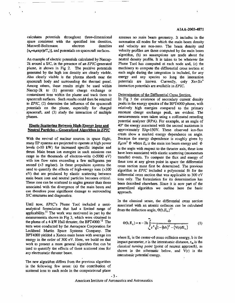
Determination of the Differential Cross Section. In Fig 3 the existence of secondary current density peaks in the energy spectra of the BPT4000 plume, with relatively high energies compared to the primary resonant charge exchange peak, are evident. The measurements were taken using a collimated retarding potential analyzer (RPA). For example, at an angle of 40" the energy associated with the second maximum is approximately E/q=150V. These observed ion-flux crests show a marked energy dependence on angle. Because the energy dependence is roughly given by Ebcos' 6 where Eb is the main ion beam energy and 6 is the angle with respect to the thruster axis, these ions have been associated with elastic scattering (momentum transfer) events. To compute the flux and energy of these ions at any given point in space the differential cross section must first be determined. The previous algorithm in EPIC included a polynomial fit for the differential cross section that was applicable to 300 eV ions only. The formulation for its determination has been described elsewhere. Since it is now part of the generalized algorithm we outline here the basic approach.
In the classical sense, the differential cross section associated with an atomic collision can be calculated from the deflection angle,
where E, is the center-of-mass collision energy, b is the impact parameter, r is the interatomic distance, rm is the classical turning point (point of nearest approach), as shown in the schematic below, and V(r) is the interatomic potential energy.
- 3 - American Institute of Aeronautics and Astronautics

,
AIAA-2003-4871
b
t I
Classical scattering trajectory.
The classical turning point is the largest equation,
root of the
(2)
which is now computed in the revised algorithm. Since it is impossible to distinguish between positive and negative deflections in the lab when’ measuring the scattering intensity at a given angle, the scattering angle in the center of mass frame, 8, is given by:
The elastic differential cross section is obtained from equation (4):
(4)
where (3 is the collision cross section. The solid angle is given by dQ=2n sine de. The differential cross section for ions in an ion-neutral charge-exchange pair such as Xe’ + Xe is calculated as follows:
In EPIC, given the angle and energy for each scattering pair (s-point to f-node as it will be shown in the next section), the impact parameter is obtained by solving equation (1) using a Newton-Raphson method. The solution requires upriori knowledge of the interatomic potential function, V(r), which may in general have both attractive and repulsive contributions. The attractive part may lead to a singularity in the
differential cross section. The singularity corresponds to a minimum in the deflection function (leading to the so-called rainbow angle). At the high energies of interest in the present work (>300 eV) the deflection function barely exhibits a minimum as the scattering is almost solely governed by the repulsive part of the interaction potential. In such cases the classical approach (vs. the more rigorous quantum mechanical approach14) is sufficiently accurate. Currently, only the repulsive potential function is included in EPIC. The coefficients that define the functional form of V(r) have been derived from averaged potentials by Amarouche et al..” and are also tabulated in Katz et al.” The derivative in equation (4) is obtained using a first order forward finite difference.
In the case of equal masses and a stationary target particle the deflection angles and energies in the laboratory and CM frames are simply related by,
where is the collision energy in laboratory frame. Using the relations from (6) it can be shown that the CM differential cross sections may be converted into the laboratory frame of reference using equation (7) b&low.l‘
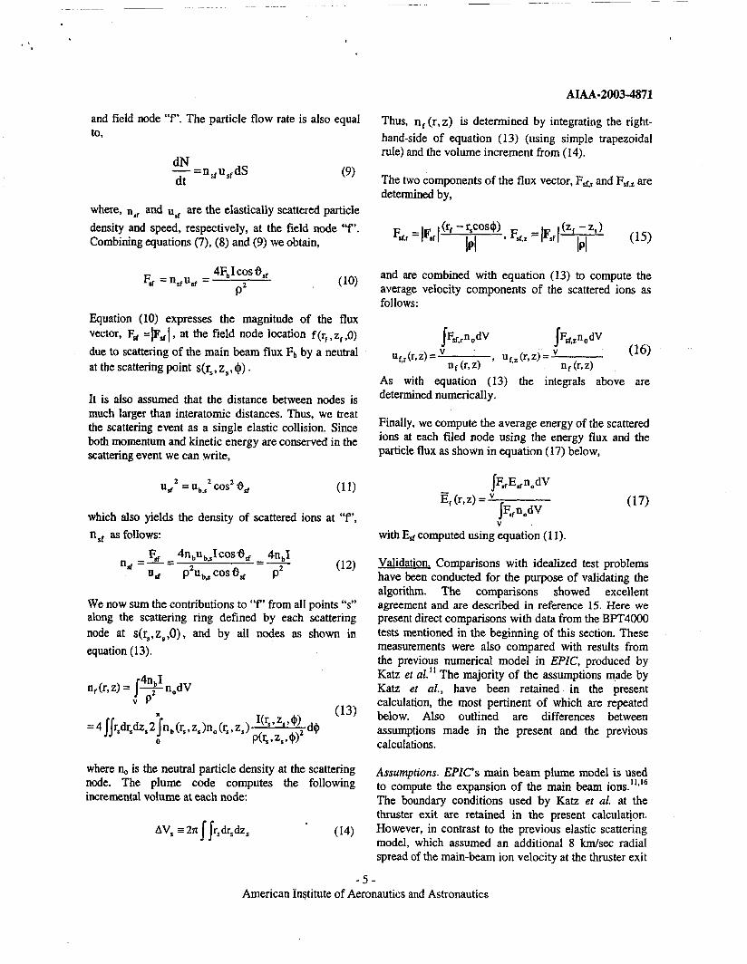
The Xe differential cross sections for pure elastic scattering in the lab frame as functions of the lab angle 6, for E,,,=300 eV and E,,,=3000 eV are shown in Fig
4.
Determination of the density. average velocity and average energy of the elastically-scattered ions. We refer to the schematic in Fig 5 to formulate the elastic scattering model. It is assumed that at the scattering point “s”, one scattering event occurs as the main beam ion flux, Fb=nb,rub,s impacts one stationary neutral particle. Once scattered, each ion does not undergo another collision. Then the particle flow rate dN/dt (#particles N per unit time t) through the incremental surface dS=p2ds2, is given by:
dN dS dt p2 -=FbI-
where, where d!2 is the solid angle subtended by dS at point “s”, I = Iio,,(e, E,) and p is the distance between “s”
- 4 - American Institute of Aeronautics and Astronautics
. I
AIAA-2003-4871
and field node “f”. The particle flow rate is also equal to.
dN - =n sf us, dS dt (9)
where, n, and us are the elastically scattered particle density and speed, respectively, at the field node “f‘. Combining equations (7), (8) and (9) we obtain,
4Fb I cos 8,, P2
E, = n,,u,, =
Equation (10) expresses the magnitude of the flux vector, Fd = psf I , at the field node location f(r,, Z, ,O) due to scattering of the main beam flux Fb by a neutral at the scattering point s(r, , z, , 9) .
It is also assumed that the distance between nodes is much larger than interatomic distances. Thus, we treat the scattering event as a single elastic collision. Since both momentum and kinetic energy are conserved in the scattering event we can write,
(1 1) 2 2 u, =Ub,* cos’s,
which also yields the density of scattered ions at “f’, nsf as follows:
We now sum the contributions to “f” from all points “s” along the scattering ring defined by each scattering node at s(r,,z,,O), and by all nodes as shown in equation (1 3).
Thus, n f (r,z) is determined by integrating the right- hand-side of equation (1 3) (using simple trapezoidal rule) and the volume increment from (14).
The two components of the flux vector, FSf,, and Frf,z are determined by,
and are combined with equation (13) to compute the average velocity components of the scattered ions as follows:
Finally, we compute the average energy of the scattered ions at each filed node using the energy flux and the particle flux as shown in equation (17) below,
V with E,f computed using equation (1 1).
Validation. Comparisons with idealized test problems have been conducted for the purpose of validating the algorithm. The comparisons showed excellent agreement and are described in reference 15. Here we present direct comparisons with data from the BE4000 tests mentioned in the beginning of this section. These measurements were also compared with results from the previous numerical model in EPIC, produced by Katz et al.” The majority of the assumptions made by Katz et al., have been retained in the present calculation, the most pertinent of which are repeated below. Also outlined are differences between assumptions made in the present and the previous calculations.
where &, iS the neutral particle density at the Scattering node. The plume code computes the following incremental volume at each node:
Assumptions, ~ p z c ‘ ~ main beam plume model is used to compute the expansion of the main &am ions.”,“ The boundary conditions used by Katz et al. at the thruster exit are retained in the present calculatjon.
AV, =2n r,dr,dz, (14) However, in contrast to the previous elastic scattering model, which assumed an additional 8 M s e c radial spread of the main-beam ion velocity at the thruster exit
II - 5 -
American institute of Aeronautics and Astronautics

I '
AIAA-2003-4871
(based on data from SPT-140 engine"), no additional beam spread is included here. As in the previous calculations, the electron temperature is assumed to be 8 eV. The computed main beam plume is shown in Fig 6, left. The expansion of neutrals from the thruster is computed using an annular anode gas flow model with isotropic emission from the ring.' The hollow cathode neutrals are assumed to have an isotropic emission at a constant temperature, equal to cathode orifice temperature (assumed to be 538°C). The maximum particle density, combining thruster and cathode neutrals, is found to be 3.87e18 m-3. It is noted that in contrast to the elastic scattering calculations by Katz er al., which assumed that all the neutral gas from the thruster was generated 0.1 m above the thruster centerline due to the simplified beam geometry assumed for the calculations, no such assumptions are required here. The chamber background density is assumed to be constant. The value of background pressure for the plume calculations is taken to be 3.3e-5 Torr, and is higher than measured (by about a factor of three) but consistent with integrated current and performance measurements. It is noted that the measured values were obtained using ionization gauges placed at each end of the chamber (upstream and downstream of the thruster), close to the re-entrant cry~pumps.'~ Using an ideal gas law the particle density of background neutrals is 1.06e18 m-3. As it will be shown next, also included in the comparisons are results for the minimum and maximum chamber pressures measured, 0.96e-5 and 4.56e-5 Torr, respectively. Ion-ion collisions have been not been included in the calculation.
The computed particle density of the elastically scattered ions is depicted in Fig 6 (right). Also shown is the main beam ion density (left). In Fig 7 we compare results from the elastic scattering calculation for &(q)/Eb, with the data taken lm away from the thruster exit, where q is the plume half angle. It is noted that the values for 55" and 65' in Fig 7 are rough estimates from broad peaks. The average energy of the main beam ions, E, , is found to be 273 eV. Also shown for comparison in Fig 7 is the square of cos(q). Since the energy is averaged over the ion flux (see equation 17) only minor differences are exhibited at the different background chambers. Thus, only the case of 3.3e-5 Torr is shown. By contrast, the computed flux of scattered ions l m from the thruster exit F i g 8) is greatly affected by the background density, as expected.
8 have not accounted for the reduction of the elastically-scattered ion flux due to charge-exchange collisions, and are therefore an upper-bound estimate. In the calculations by Katz, et al. as much as 60% of the flux reaching the detector was assumed to be lost by charge-exchange scattering.
Preliminam Assessment of the Effects of ElaStic Scattering on Spacecraft Emplovhq
High-Power Ion Propulsion
To obtain a first quantitative idea about possible concerns elastically scattered ions may pose to spacecraft with high power ion propulsion systems, we present a calculation representative of NASA's Evolutionary Xenon Thruster (NEXT). NEXT is the next generation ion propulsion system developed by NASA to follow the NSTAR (NASA Solar Electric Propulsion Technology Applications Readiness) engine.'' The system is to include (among others) a 40 cm diameter ion thruster. Tests performed at NASA Glenn Research Center (GRC) using a Laboratory Model (LM) 40-cm engine produced performance data for a relatively wide power range 1.1-6.9 kW.'8*'9 We therefore use NEXT as a representative example to assess the consequences of elastically-scattered ions as mission requirements transition from low to high power ion propulsion.
Table 1. Parameters used to compare the effects of elastically-scattered ions at two different power levels of a NEXT-class ion propulsion system.

t
AIAA-2003-4871
calculations. The average ion beam energy (in ev) is estimated in expression (18) using the thrust T and beam current Jb from Table 1, with (q/m) being the charge-to-mass ratio for Xe.
2
E’=--( I q T ) 2 m Jb
The density of neutrals expelled from the thruster is estimated using the assumed propellant utilization, the discharge chamber flow rate, the thruster radius and the speed of neutrals. The latter is assumed to be 140 mlsec for both cases. The sum of the main beam and elastically-scattered ion density is illustrated by the contour line plot in Fig 9 (bottom), computed for Case 1. To quantify the enhanced degradation of surrounding surfaces from beam Case 1 (625 eV beam) to Case 2 (1671 eV beam) we place an imaginary panel covered by a typical spacecraft material coating (e.g. Indium Tin Oxide (ITO), Kapton etc.) 50 cm from the thruster also shown in Fig 9 (bottom). The change in erosion of the panel due to sputtering by the two beams, 625 eV and 167 1 eV, can be expressed by the ratio:
where, Y(Ei ,p) is the sputter yield for panel material (in atomdion) as a function of incident ion energy Ei (ev) and incidence angle p (rad), and Fi denotes the incident ion flux (m%x-’). We choose a typical sputter yield functional form at normal incidence that incorporates a linear dependence of the yield with energy as shown in equation (20).
Ye, ,p = 0) = clEi + c2 (atomdion) (20) c, = 0.001, c2 = 0.01
- S as a function of distance from the thruster exit along the panel is illustrated in Fig 9 (top). As expected, for z>OS m erosion is dominated by main beam ion flux. For the part of the panel that falls with the main beam, erosion due to main beam ions is more than five orders of magnitude higher than erosion due to elastically scattered ions. Of particular interest is the erosion enhancement with increased beam energy at the larger plume angles, where no main beam ions are reaching the panel. We find that the minimum value of 3 for zc0.5m is about 13, which translates to 13 times higher erosion for a factor of 2.7 increase in beam energy and 8.4 times increase in the jet power (0.57 to 4.8 kW).
This is not unexpected since erosion due to elastic scattering, 3, , only equations (lo), (1 1) and (19). lead to the following scaling (along the panel):
For example, at z-0.5m on the panel, 6 4 0 deg and the differential cross section ratio Iz/11=0.77. Substitution of all remaining values from Table 1 into equation (21) yields 5==13.3 which is indeed approximately the computed value at this location as shown in Fig 9.
Conclusions
The development of EPIC for NASA’s SEE program has proceeded this year with a number of accomplishments towards the toolset’s final version. A variety of required features within each main component of EPIC, such as ‘Thruster” specifications in Object Toolkit have been successfully implemented. Expansion of the toolset’s range of applicability has also been demonstrated through a Nascap-2k calculation that incorporated an EPZC-generated plume and S/C (the latter produced by Object Toolkit which is the geometry definition module for both codes). The exchange was accomplished using the SOAP (Simple Object Access Protocol) protocol. The need to assess the effects of high-energy plume ions (>300 eV) on S/C equipment and critical surfaces surrounding the propulsion system, also prompted the revision of EPZC‘s existing algorithm that previously computed elastically-scattered ions with energies less than 300 eV. Results from the revised algorithm have been compared with lab measurements taken in the plume of a 4-kW Hall thruster showing good agreement with the angular distribution of energy and ion flux. In view of the need to quantify the effects of these ions, as new mission requirements demand EP power levels in the tens of kilowatts, preliminary calculations have compared two ion beam cases that are representative of the ion propulsion system NEXT. The calculations suggest that for plume angles beyond the maximum main beam divergence (Le. >40 deg half-angle), as much as 13 times higher erosion of typical SIC material due to elastically-scattered ions may be expected as the power level is increased from 1.1 to 6.9 kW. The results,reveal the need for plume measurements in high- power ion engines to further validate the predictive capability of models such as the one presented in this paper.
- 7 - American Institute of Aeronautics and Astronautics

.
AIAA-2003-4871
Acknowledgments
This work is supported by the Space Environments and Effects (SEE) Program at the NASA Marshall Space Flight Center under contract no. NAS 8-02-028.
References
I Mikellides. I.G., Kuharski, R.A., Mandell, M.J., Gardner, B.M., ”Assessment of Spacecraft Systems Integration Using The Electric Propulsion Interactions Code (EPIC),” AIAA Paper 2002-3667, July 2002.
Fife, J.M., et al., ‘The Development of a Flexible, Usable Plasma Interaction Modeling System,” AIAA Paper 2002-4267, July 2002.
Purrin, V., Pogarieloff, D., Metois, P., and Brosse, S.. “PPS Effects on Satellites Analyses and Tools in Alcatel Space Industries,” IEPC Paper 01-262, Oct. 2001.
Davis, V.A., et al., “Ion Engine Generated Charge Exchange Environment: Comparison Between NSTAR Flight Data and Numerical Simulations,” AIAA Paper
Jongeward, G.A., et al., “High Voltage Solar Arrays for a Direct Drive Hall-Effect Propulsion System,” EPC Paper 01-327, Oct. 2001.
Gardner, B.M., Katz, I., Davis, A. and Mandell, M. “Hall Current ‘Thruster (HCT) IR&D Plume Environment Characterization and Electrostatic Return Current Assessment” Final Report for Lockheed Martin Space Systems Company (MTSD-DPR-01-16648). Jan. 2001.
Mikellides, I.G., “A Hall-Effect Thruster Plume and Spacecraft Interactions Modeling Package,” E P C Paper 2002-251, Oct. 2001. * Gardner, B.M., et al., “Electric Propulsion Interactions Code, EPIC,” Final Report, Prepared under NASA Contract #NAS8 02028, No. SAIC 022043, Nov. 2002.
Mandell, M.J., et al., “Nascap-2k, A Spacecraft Charging Analyis Code for the 21’‘ Century,” AIM Paper 2001-0957, Jan. 2001. lo httv://www.w3.or~RlSOAP/
Katz, I., et al., “A Hall Effect Thruster Plume Model Including Large-Angle Elastic Scattering,” AIAA Paper
l2 Pollard, J.E., et al., “Ion Flux, Energy, Charge-State Measurements for the BPT-4000 Hall Thruster,” AIAA Paper 01-3351, July, 2001. l3 Amarouche, M., Durand, G. and Marlieu, J.P., “Structure and Stability of Xe; Clusters,” J. Chem.
00-3529, July 2000.
I 1
01-3355, July 2001.
Physics, VOl. 88, 1988, pp. 1010-1018.
l 4 Moa, N.F., and Massey, H.S.W., The Theory of Atomic Collisions, Ch. I,V and XII, Clarendon Press, Oxford, 1949. l5 Mikellides, I.G., et al. “The Electric Propulsion Interactions Code (EPIC): A Member of the NASA Space Environment and Effects Program (SEE) Toolset,” Presentation for AIAA Paper 2003-487 1, July 2003. l6 Mikellides, I.G., et al., “F‘lume Modeling of Stationary Plasma Thrusters and Interactions with the Express-A Spacecraft,” Journal of Spacecraft and Rockets, Vol. 39, No. 6,2002, pp. 894-903. I’ Pollard, J.E., and Beiting, E.J., “Ion energy, ion velocity, and thrust vector measurements with the SPT- 140 hall thruster,” 3& International Conference on Spacecraft Propulsion, 10-13 Oct 2000, Cannes, France. ’* Patterson, M.J., et al., “NEXT: NASA’s Evolutionary Xenon Thruster,” AIAA 2002-3832, July 2002. 19 Soulas, G.C., Haag, T.W., and Patterson, M.J., “Performance Evaluation of 40 cm Ion Optics for the NEXT Ion Engine,” AIAA 2002-3834, July 2002.
- 8 - American Institute of Aeronautics a& Astrocactics

.
AIAA-2003-4871
Parameter
r.-. ... .. - __ 1
Panel
Fig 2. Prototype Nascap-2k calculation of potentials near spacecraft (black outlined red cells) resulting from an EPZC- generated plume. The plume densities were imported from EPZC using SOAP. Noted is the plasma sheath near the spacecraft (lower right) and near the thermal panel (center).
- 9 - American Institute of Aeronautics and Astronautics
AlAA-2003-4871
Energy Spectra at Different Angles 0 35 I 0.30
E
3 0.20 2
0.15
N 0.25
9 t? C
c 0 C
0 5 0.10
0 .OD
Thruster Beam Peak h
It Elastic Scattering Peak ;
0 50 100 150 200 250 300
Efq 0
Fig 3. Collimated RPA data for the BPT-4000 at discharge power of 3kW and voltage of 300V showing the angle- independent, high-energy main beam peaks and the angle-dependent, elastic scattering peaks (data taken at The Aerospace Corporation by Jim Pollard et d'')
1 .Id
h I-
$ 5 a i! 3 2: .d
E: .s 8 Y
cn
100
10
1
0.1
0.0 1
. : i 1 t . i 1 ; I i I ! ! t . ? I
I ! / / ,
''lo3 !I 5 10 i5 20 25 30 35 40 45 50 55 60 65 70 75 80 85 90 !!5 Deflection Angle in Lab Frame (deg)
300 eV 3000 eV
- ---- Fig 4. Classical differential cross section as a function of angle in the lab-frame', ~*I,,(E,,B)*CO~~, for the Xe+Xe+ elastic scattering pair at &,L=300 eV and 3000 eV.
- 10- American Institute of Aeronautics and Astronautics

AIAA-2003-4871
i
I Scattering node
Fig 5. Elastic scattering arrangement used to formulate the generalized algorithm in EPIC'S plume tool. Plane defined by the four red comers is a portion of the plume computational plane.
Fig 6. Computed main beam (left) and elastically-scattered ion density (right) (using the new EPIC algorithm), in the plume of the BPT4000 engine operating in the laboratory (P=3.3e-5 Torr).
- 1 1 - American Institute of Aeronautics and Astmnautics

AIAA-2003-4871
0 10 20 30 40 50 60 70 80 90
Plume Angle, q (deg)
Fig 7. Comparisons between computed energy of elastically-scattered ions Ef(q)and measurements in the plume of the BPT4000 engine operating in the lab. Plotted is the ratio of elastically-scattered ion energy over the main beam energy E, estimated to be approximately 273 eV.
1
h (Y
E
0 3 1 0.1
c
ii a
0.01 0 10 20 30 40 50 60 70 80
Plume angle, q (deg)
Fig 8. Comparisons between computed flux of elastically-scattered ions for three chamber pressures, and measurements in the plume of the BPT4000 engine.
,
- 12- American Institute of Aeronautics and Astronautics

Ion EI
AIM-2003-4871
14 I I I
12
g 11 0 - +.
E 0 - 3 10 w
9
8
I
I 0.2 0.4 I 0.8 one
8
0.2 0.4 I 0.6 0.8 1 1.2 1.4
IUM’J I I 1 i 1 5 ’ ~
1 .o 1.2 I
X I I I
I ’ I
Fig 9. Erosion along a “test” panel due to the plume from an ion engine operating at I. lkW and 6.9 kW. The panel is located 50 cm from the thruster centerline. The plume was computed using EPIC’S main beam and (recently-updated) elastic scattering algorithms (main beam and elastically scattered ion density contours, in mV3, for Case 1 are shown in the bottom).
- 1 3 - American Institute of Aeronautics and Astrona~tics