ai pb en - novexx · pdf fileproduct description ai 08/2017 | 00 5 interface description...
TRANSCRIPT

PRODUCT DESCRIPTION
AIApplikator Interface
Edition 7 - 8/2017

Product description AI
Content
Interface description -5Important notes -5Firmware requirements -5Connector Position -6Connections and configuration -8
Replacing older boards -10
Layout diagram -11
Block diagram -12
Circuit diagrams for signal inputs -13
Circuit diagrams for signal outputs -14
Pin assignments -16Applicator connection -16
Novexx-Applicator-connection -18
Machine status connection -19
Product sensor connection -21
Signal LEDs -23
Applicator Operation -24Function -24
Connecting an applicator -26
Selecting an applicator type -27
Signal-Time-Diagrams -28Time/sensor controlled applicators -28
PEP IV / LA-TO timed / LA-SO -29
PEP Blow On / LA-TO BO timed -30
Reverse PEP -31
LTP / LTPV / LA-TO BO Sensor -32
PEP II sensor / LA-TO sensor -33
ASA / LA-BO -34
08/2017 3 Content

Product description AI
08/2017 4 Content
Product description AI
INTERFACE DESCRIPTION
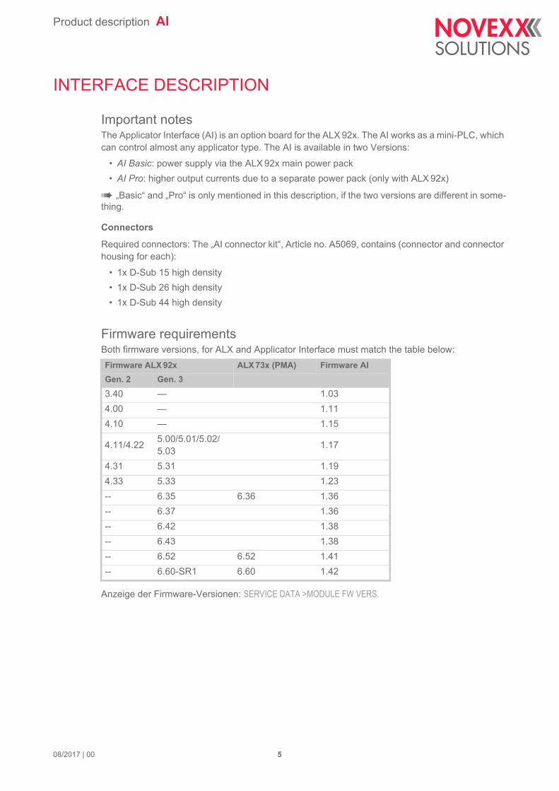
Important notesThe Applicator Interface (AI) is an option board for the ALX 92x. The AI works as a mini-PLC, which can control almost any applicator type. The AI is available in two Versions:
• AI Basic: power supply via the ALX 92x main power pack
• AI Pro: higher output currents due to a separate power pack (only with ALX 92x)
„Basic“ and „Pro“ is only mentioned in this description, if the two versions are different in some-thing.
Connectors
Required connectors: The „AI connector kit“, Article no. A5069, contains (connector and connector housing for each):
• 1x D-Sub 15 high density
• 1x D-Sub 26 high density
• 1x D-Sub 44 high density
Firmware requirementsBoth firmware versions, for ALX and Applicator Interface must match the table below:
Anzeige der Firmware-Versionen: SERVICE DATA >MODULE FW VERS.
Firmware ALX 92x ALX 73x (PMA) Firmware AI
Gen. 2 Gen. 3
3.40 — 1.03
4.00 — 1.11
4.10 — 1.15
4.11/4.225.00/5.01/5.02/5.03
1.17
4.31 5.31 1.19
4.33 5.33 1.23
-- 6.35 6.36 1.36
-- 6.37 1.36
-- 6.42 1.38
-- 6.43 1.38
-- 6.52 6.52 1.41
-- 6.60-SR1 6.60 1.42
08/2017 | 00 5
Product description AI
Connector Position
ALX 92x
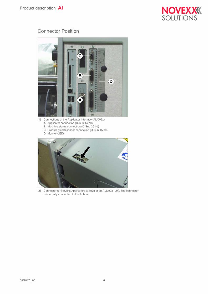
[1] Connections of the Applicator Interface (ALX 92x):A Applicator connection (D-Sub 44 hd)B Machine status connection (D-Sub 26 hd)C Product (Start) sensor connection (D-Sub 15 hd)D Monitor-LEDs
[2] Connector for Novexx Applicators (arrow) at an ALS 92x (LH). The connectoris internally connected to the AI board.
D
C
B
A
08/2017 | 00 6
Product description AI
ALX 73x
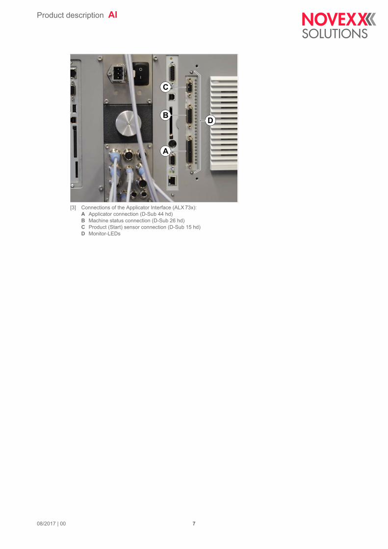
[3] Connections of the Applicator Interface (ALX 73x):A Applicator connection (D-Sub 44 hd)B Machine status connection (D-Sub 26 hd)C Product (Start) sensor connection (D-Sub 15 hd)D Monitor-LEDs
D
C
B
A
08/2017 | 00 7
Product description AI
Connections and configuration
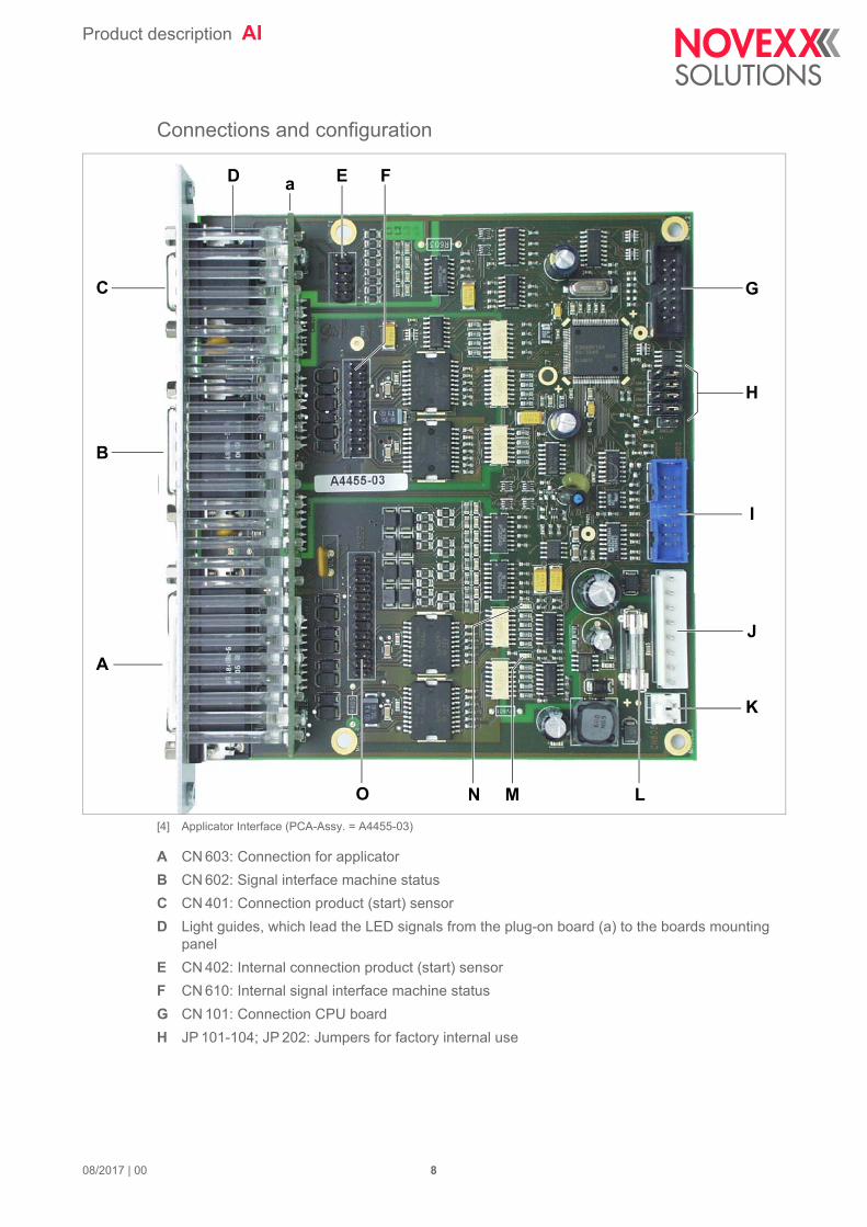
[4] Applicator Interface (PCA-Assy. = A4455-03)
A CN 603: Connection for applicator
B CN 602: Signal interface machine status
C CN 401: Connection product (start) sensor
D Light guides, which lead the LED signals from the plug-on board (a) to the boards mounting panel
E CN 402: Internal connection product (start) sensor
F CN 610: Internal signal interface machine status
G CN 101: Connection CPU board
H JP 101-104; JP 202: Jumpers for factory internal use
A
B
C
H
I
J
D
K
O L
a
G
E F
MN
08/2017 | 00 8

Product description AI
[5] Default settings for the jumpers JP 101-104 and JP 202.
I CN 102: Debug interface
J CN 604: Connection power supply
K CN 605: not used
L SI 601: Fuse
– AI Basic: T1AH 250V (article no.: A2328)– AI Pro: T4AH 250 V (article no.: A5179)
M D 331: Green LED; only for factory internal use; flashes if the AI works properly
N D332: Yellow LED; only for factory internal use
O CN 609: Internal connection applicator
JP104JP103JP102JP101JP202
08/2017 | 00 9
Product description AI
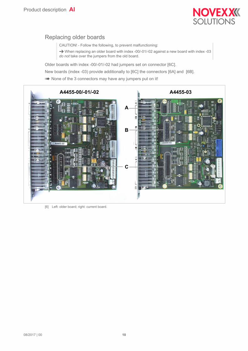
Replacing older boards
Older boards with index -00/-01/-02 had jumpers set on connector [6C].
New boards (index -03) provide additionally to [6C] the connectors [6A] and [6B].
None of the 3 connectors may have any jumpers put on it!
[6] Left: older board; right: current board.
CAUTION! - Follow the following, to prevent malfunctioning:
When replacing an older board with index -00/-01/-02 against a new board with index -03 do not take over the jumpers from the old board.
A4455-00/-01/-02 A4455-03
A
B
C
08/2017 | 00 10
Product description AI
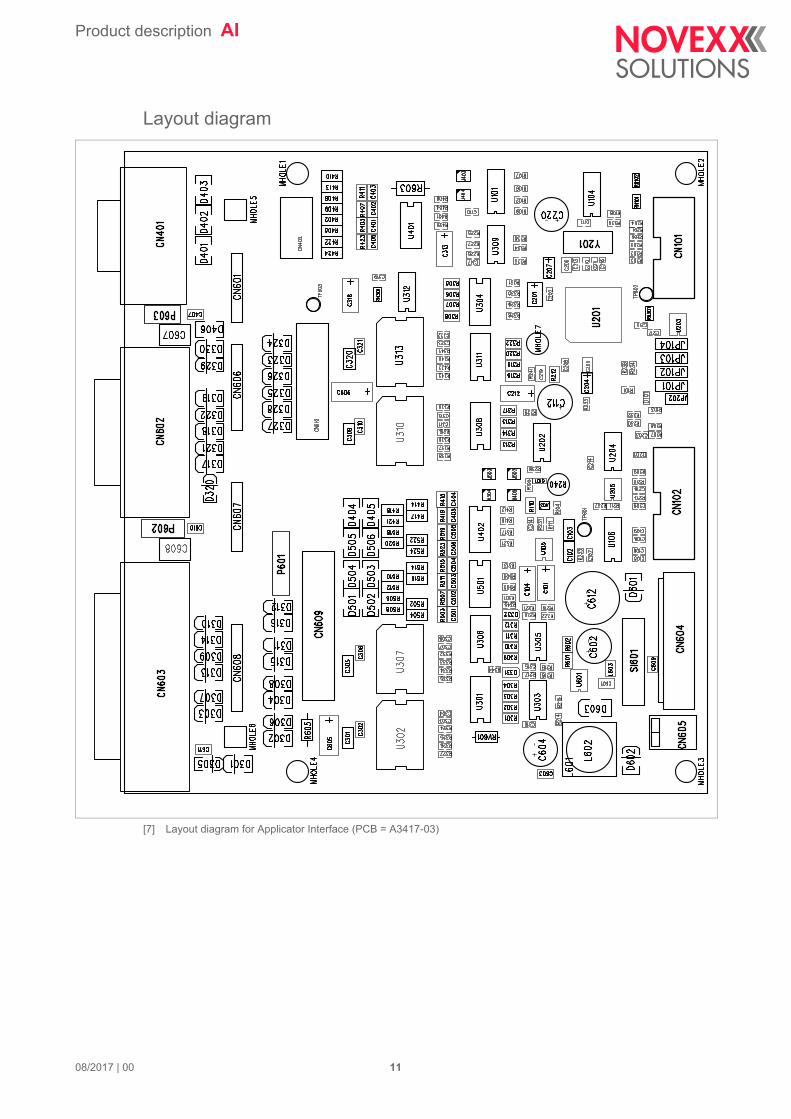
Layout diagram
[7] Layout diagram for Applicator Interface (PCB = A3417-03)
08/2017 | 00 11
Product description AI
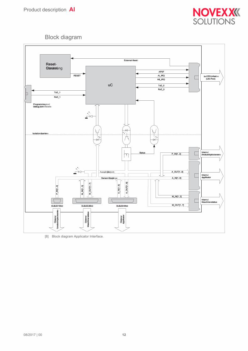
Block diagram
[8] Block diagram Applicator Interface.
COM_0
COM_1
ResetControl
RESET
External reset
TxD_0
RxD_0
APSF
AI_IRQ
H8_IRQ
TxD_1
RxD_1
Programming anddebug port
to CPU board
(USI Port)
uC
Exte
rna
lp
rod
uct
ligh
tb
arr
ier
Isolation barrier
Status
Outputs
M_
OU
T[1
..7
]
A_
OU
T[1
..8
]
Sensor inputs
P_
IN[1
..3
]
D-SUB 15hd
M_
IN[1
..3
]
D-SUB 26hd
A_
IN[1
..6
]
D-SUB 44hd
Internalapplicator
A_OUT[1..8]
A_IN[1..6]
P_IN[1..3]
M_IN[1..2]
M_OUT[1..7]
Internalproduct light barrier
Internalmaschine status
Exte
rna
lm
asch
ine
sta
tus
Exte
rna
la
pp
lica
tor
Reset-Steuerung
RESET
Externer Reset
TxD_0
RxD_0
APSF
AI_IRQ
H8_IRQ
TxD_1
RxD_1
Programmier-/Debug-Schnittstelle
zur CPU-Platine
(USI-Port)
uC
Exte
rnP
rod
uktlic
hts
ch
ran
ke
Isolationsbarriere
Status
Ausgänge
M_
OU
T[1
..7
]
A_
OU
T[1
..8
]
Sensor-Eingänge
P_
IN[1
..3
]
SUB-D15hd
M_
IN[1
..3
]
SUB-D26hd
A_
IN[1
..6
]
SUB-D44hd
InternApplikator
A_OUT[1..8]
A_IN[1..6]
P_IN[1..3]
M_IN[1..2]
M_OUT[1..7]
InternProduktlichtschranke
InternMaschinenstatus
Exte
rnM
asch
ine
nsta
tus
Exte
rnA
pp
lika
tor
08/2017 | 00 12
Product description AI
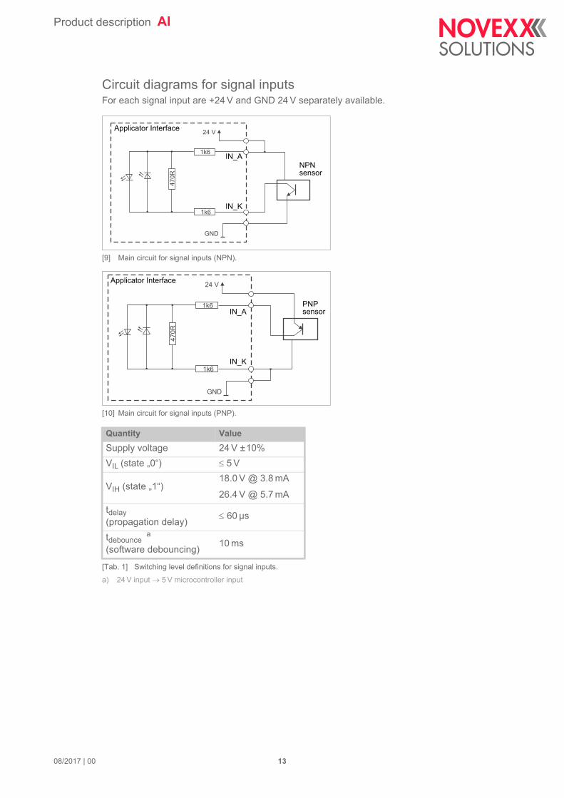
Circuit diagrams for signal inputsFor each signal input are +24 V and GND 24 V separately available.
[9] Main circuit for signal inputs (NPN).
[10] Main circuit for signal inputs (PNP).
Quantity Value
Supply voltage 24 V ±10%
VIL (state „0“) 5 V
VIH (state „1“)18.0 V @ 3.8 mA
26.4 V @ 5.7 mA
tdelay (propagation delay)
60 µs
tdebounce a
(software debouncing)
a) 24 V input 5 V microcontroller input
10 ms
[Tab. 1] Switching level definitions for signal inputs.
1k6
24 V
GND
470R
1k6
IN_A
IN_K
Applicator Interface
NPNsensor
1k6
24 V
GND
470R
1k6
IN_A
IN_K
Applicator Interface
PNPsensor
08/2017 | 00 13
Product description AI
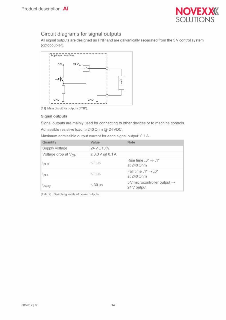
Circuit diagrams for signal outputsAll signal outputs are designed as PNP and are galvanically separated from the 5 V control system (optocoupler).
[11] Main circuit for outputs (PNP).
Signal outputs
Signal outputs are mainly used for connecting to other devices or to machine controls.
Admissible resistive load: 240 Ohm @ 24 VDC.
Maximum admissible output current for each signal output: 0.1 A.
Quantity Value Note
Supply voltage 24 V ±10%
Voltage drop at VOH 0.3 V @ 0.1 A
tpLH 1 µsRise time „0“ „1“ at 240 Ohm
tpHL 1 µsFall time „1“ „0“ at 240 Ohm
tdelay 30 µs5 V microcontroller output 24 V output
[Tab. 2] Switching levels of power outputs.
24 V
Load
GNDGND
Applicator Interface
5 V
08/2017 | 00 14

Product description AI
Power outputs
Power outputs can directly drive loads.
Maximum admissible output current for each power output: 0.5 A: Total output current Imax over all outputs not more than:
• AI Basic: 1 A
• AI Pro: 4 A
Max power
The maximum output power drawable from the 24 V supply is:
• AI Basic: 24 W (1 A)
• AI Pro: 96 W (4 A)
This is the sum of all sensor supplies and of all switch outputs which are active at the same time.
Overload
The outputs are equipped with quad channel power switches, which are protected against overcur-rent and overtemperature as follows:
• Overtemperature of a power switch: all outputs of the power switch are turned off, until the tem-perature reaches the admissible range.
• Overcurrent of one or several outputs: the respective outputs are pulsed until the overcurrent condition is removed. During this, the output current is limited to 400 mA
During an error case, each quad channel power switch sets a diagnosis signal, which is detected and sent to the CPU by the microcontroller.
Load Max. value
Resistive load 48 Ohm @ 24 VDC
Inductive load 200 mJ
Lamp 10 W
[Tab. 3] Admissible loads at power outputs.
Quantity Value Note
Supply voltage 24 V ±10%
Voltage drop at VOH 0.5 V @ 0.5 A
tpLH 5 µsRise time „0“ „1“ at 48 Ohm
tpHL 5 µsFall time „1“ „0“ at 48 Ohm
tdelay 60 µs5 V microcontroller output 24 V output
[Tab. 4] Switching levels of power outputs.
Connection Max. current
Signal output 0.1 A
Power output 0.5 A
[Tab. 5] Maximum ouput current for each output.
08/2017 | 00 15
Product description AI
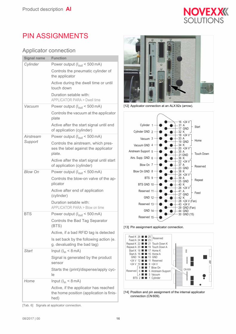
[12] Applicator connection at an ALX 92x (arrow).
[13] Pin assignment applicator connection.
[14] Position and pin assignment of the internal applicator connection (CN 609).
Cylinder
Cylinder GND
Vacuum
Vacuum GND
Airstream Support
Airs. Supp. GND
Blow On
Blow On GND
BTS
BTS GND
Reserved
GND
Reserved
GND
Reserved
Home
Touch Down
Repeat
Feed
Reserved
Start1
2
3
4
5
6
7
8
9
10
11
12
13
14
15
31 A
32 K
33 A
34 K
35 A
36 K22 +24 V37 A23 GND38 K24 +24 V39 A25 GND40 K26 +24 V41 A27 GND42 K28 +24 V (Fan)43 +24 V29 GND (Fan)44 GND30 GND (15)
16 +24 V
17 GND
18 +24 V
19 GND
20 +24 V
21 GND
BTS 24
6
8
Start A 16Start K 18
Repeat A 20Repeat K 22
Feed A 24Feed K 26
+24 V 10
+24 V 12
GND 14
1 Cylinder3 Vacuum
5 Airstream Support
7 Blow On
15 Home A17 Home K
19 Touch Down A21 Touch Down K
2325
Reserved
Reserved
9 +24 V
11 Reserved
13 GND
CN 609
PIN ASSIGNMENTS
Applicator connectionSignal name Function
Cylinder Power output (Iout < 500 mA)
Controls the pneumatic cylinder of the applicator
Active during the dwell time or until touch down
Duration setable with:APPLICATOR PARA > Dwell time
Vacuum Power output (Iout < 500 mA)
Controls the vacuum at the applicator plate
Active after the start signal until end of application (cylinder)
Airstream Support
Power output (Iout < 500 mA)
Controls the airstream, which pres-ses the label against the applicator plate.
Active after the start signal until start of application (cylinder)
Blow On Power output (Iout < 500 mA)
Controls the blow-on valve of the ap-plicator
Active after end of application (cylinder)
Duration setable with:APPLICATOR PARA > Blow on time
BTS Power output (Iout < 500 mA)
Controls the Bad Tag Separator (BTS)
Active, if a bad RFID tag is detected
Is set back by the following action (e. g. devaluating the bad tag)
Start Input (Iin < 8 mA)
Signal is generated by the product sensor
Starts the (print)/dispense/apply cyc-le
Home Input (Iin < 8 mA)
Active, if the applicator has reached the home position (application is finis-hed)
[Tab. 6] Signals at applicator connection.
08/2017 | 00 16

Product description AI
24 V supply voltage outputs:
• Sensors: Imax = 10 mA
• Fan (pin 28):
– AI Basic: Imax = 1 A– AI Pro: Imax = 4 A
• Pin 43/44: Imax = 100 mA
Total output current Imax over all outputs not more than:
• AI Basic: 1 A
• AI Pro: 4 A
Touch Down Input (Iin < 8 mA)
Use with sensor-controlled applica-tors (e. g. LTP)
Active, if the applicator touches the product
Repeat Input (Iin < 8 mA)
Labeler: Starts a dispense/apply cyc-le
Print & Apply system: Repeats the last print/dispense/apply cycle
Feed Input (Iin < 8 mA)
Feeding of the label material as long as the signal is active; at least one la-bel is dispensed
Signal name Function
[Tab. 6] Signals at applicator connection.
08/2017 | 00 17

Product description AI
[15] Connector (arrow) for Novexx-Applicators
[16] Pin assignment Novexx-Applicator connection
+24 V (Fan)
GND (Fan)
Cylinder
Vacuum
Blow On
Home Position
Touch Down
Airstream Support
Valve Power
ReservedN. C.
Motor B\
Motor A\
Motor B
Motor A
1
2
3
4
5
9
10
11
12
136
7
8
14
15
Novexx-Applicator-connectionThis connection is only available at an ALX 92x.
Signal description see Applicator connection on page 16.
08/2017 | 00 18

Product description AI
[17] Machine status connection at an ALX 92x (arrow).
[18] Pin assignment machine status connection.
[19] Position and pin assignment of the internal machine status connection (CN 610).
Error
Error GND
Warning
Warning GND
Ready
Ready GND
Cycle
Cycle GND
OD Foil
PLC start
Inhibit
OD sensor in
1
2
3
4
5
6
7
8
9
19 A
20 K
21 A
22 K
23 A
24 K16 OD sensor25 Offline17 OD sensor GND26 Offline GND18 OD Foil GND
10 +24 V
11 GND
12 +24 V
13 GND
14 +24 V
15 GND
PLC start A 2Inhibit A 4
not used 6
OD sensor 8
+24 V 16GND 18
OD sensor in A 20
Offline 10
n. c. 12
+24 V 14
1 PLC start K3 Inhibit K
5 Error
7 Warning
15 +24 V17 GND
19 OD sensor in K
9 Ready
11 Cycle
13 Key
CN 610
Machine status connection24 V supply voltage outputs: Imax =10 mA
Signal name Function
Error Power output (Iout < 500 mA)
Signal active when an error message appears on the operator panel dis-play
Warning Power output (Iout < 500 mA)
Active, if a warning status occurs (e. g. label roll diameter below desired nominal value)
Ready Power output (Iout < 500 mA)
Active in online mode, if a printjob is loaded.
If Ready is active, the machine starts to print and dispense immediately af-ter arrival of a start signal.
Cycle Power output (Iout < 500 mA)
Active during application cycle (start signal up to homeposition signal)
OD foil Power output (Iout < 500 mA)
Active, if the foil roll Ø fell below the value set in SYSTEM PARAMETER > Foil end warning
PLC start Input (Iin < 8 mA)
Same function as start signal, see chap. Applicator connection on page 16
Inhibit Input (Iin < 8 mA)
Start signals are ignored, while signal is active
OD sensor in Input (Iin < 8 mA)
Connection for optional roll outer dia-meter (OD) sensor, see service ma-nual, topic section „Electronics Gen. 3“, chapter „OD sensor (ALX 92x)“.
OD sensor Power output (Iout < 500 mA)
May be used for driving a signal lamp indicating that the roll Ø is low.
Active (0 V), if the OD light barrier is closed (roll Ø is to small).
Active (0 V), if no OD sensor is connected.
Inactive (24 V), if the OD light barrier is open (roll Ø is sufficient).
[Tab. 7] Signals at machine status connection.
08/2017 | 00 19

Product description AI
Offline Power output (Iout < 500 mA)
Active in offline mode
Signal name Function
[Tab. 7] Signals at machine status connection.
08/2017 | 00 20
Product description AI
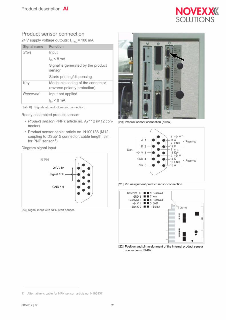
[20] Product sensor connection (arrow).
[21] Pin assignment product sensor connection.
[22] Position and pin assignment of the internal product sensor connection (CN 402).
A
StartK
+24 V
GND
Key
Reserved
Reserved
A
K
Key
K
A
+24 V
GND
n. c.
+24 V
GND
1
2
3
4
5
11
12
13
14
15
6
7
8
9
10
Start K 2+24 V 4
Reserved 6
GND 8
Reserved 10
1 Start A3 GND
5 Reserved
7 Key
9 Reserved
CN 402
Product sensor connection24 V supply voltage outputs: Imax = 100 mA
Ready assembled product sensor:
• Product sensor (PNP): article no. A7112 (M12 con-nector)
• Product sensor cable: article no. N100136 (M12 coupling to DSub15 connector, cable length: 3 m, for PNP sensor 1)
Diagram signal input
[23] Signal input with NPN start sensor.
Signal name Function
Start Input
Iin < 8 mA
Signal is generated by the product sensor
Starts printing/dispensing
Key Mechanic coding of the connector (reverse polarity protection)
Reserved Input not applied
Iin < 8 mA
[Tab. 8] Signals at product sensor connection.
1) Alternatively: cable for NPN sensor: article no. N100137
1NPN
24V / br
Signal / bk
GND / bl
08/2017 | 00 21
Product description AI
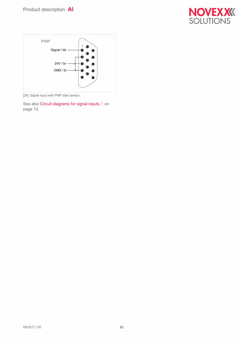
[24] Signal input with PNP start sensor.
See also Circuit diagrams for signal inputs on page 13.
1PNP
24V / br
Signal / bk
GND / bl
08/2017 | 00 22
Product description AI
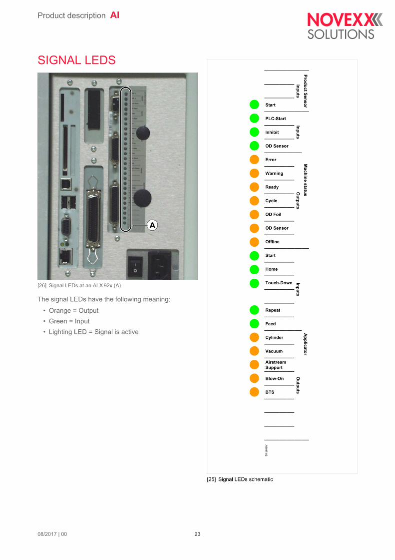
[25] Signal LEDs schematic
Product Sensor M
achine statusA
pplicatorinputs
InputsO
utputsInputs
Outputs
Start
PLC-Start
Inhibit
OD Sensor
Error
Warning
Ready
Cycle
OD Foil
OD Sensor
Offline
Start
Home
Touch-Down
Repeat
Feed
Cylinder
Vacuum
Airstream Support
Blow-On
BTS
A5197-02
SIGNAL LEDS
[26] Signal LEDs at an ALX 92x (A).
The signal LEDs have the following meaning:
• Orange = Output
• Green = Input
• Lighting LED = Signal is active
A
08/2017 | 00 23

Product description AI
APPLICATOR OPERATION
FunctionIf direct labelling from the dispensing edge is not possible, the labeller can be equipped with an ap-plicator. In applicator mode, the applicator takes the label from the dispensing edge and carries it to the product.
The labeller can be equipped with various applicators, depending on the need. Those applicators are all driven by compressed air. The following are possible:
LTP / LTPV
LTP (Light Touch Pneumatic) and LTPV (Light Touch Pneumatic Vacuum):
Applicator with „Light Touch“ function. „Light Touch“ means, that the movement of the (compressed air) cylinder is limited by sensors, which react to a light touch onto the product. The LTPV addition-ally sucks the labels on with a vacuum nozzle.
Advantages:
• Application on products with different heights possible
• Only light pressure onto the product (important with sensitive products)
PEP IV
The cylinder movement is limited by a setable length of time. After the run out of this application time, the applicator moves back into home position.
PEP Blow on
PEP-type applicator with blow on function: After run out of the application time, the blow on function is activated. After run out of the blow on time, the applicator moves back into home position.
PEP II Sensor
The cylinder movement is limited by a (touch down) sensor, which signals the contact to the product and triggers the backwards-movement.
ASA
ASA (Air Stream Applicator)
This applicator type has no moving parts, but blows the label onto the product (also called „blow box“). After the start signal, the blow on valve is opened for a setable time length.
Reverse PEP
This applicator is partly time related. Working procedure:
The applicator moves to its end position and “waits“ for the start signal. The start signal triggers the blow on valve which is active for the defined blow on time. After the run out or the blown on time, the applicator moves to home position, gets the next label and moves to the wait position.
BTS
BTS (Bad Tag Separator)
This device does the opposite of an applicator: it removes labels from the dispensing edge of a la-beller. The BTS is used for sorting out RFID labels, which could not be read/written properly.
08/2017 | 00 24
Product description AI
LA-BO
The LA-BO (Label Applicator Blow On) is a blow-on applicator. It works like the ASA does (see above).
LA-SO
The LA-SO (Label Applicator Swing On) attaches the label with a rotating movement of its swivel-ling arm to the product.
LA-TO
The LA-TO (Label Applicator Tamp On) is a classic tamp-on applicator, which is available time con-trolled or sensor controlled. The sensor control is done optionally by an end position sensor (LA-TO sensor) or by a touchdown sensor (LA-TO TD), which is triggered, when the applicator touches the product.
LA-TO BO
LA-TO with additional blow-on function. The applicator first moves to the end position and then it blows the label over the remaining stretch onto the product, without the applicator foot touching the product. The LA-TO BO is available sensor or time controlled.
08/2017 | 00 25

Product description AI
Connecting an applicatorDepending on the applied applicator type, different input and output signals are used.
The following applicator types, which are distributed by Novexx Solutions, can be connected direct-ly to the connector for Novexx applicators, using the delivered cable, see .
• LTP / LTPV
• PEP IV
• BTS
• LA-BO
• LA-TO (all versions)
• LA-SO
For all other applicator types, the connection cable must be configurated by the system integrator.
Applicator types:
LT
P(V
)
PE
P
LA
-TO
tim
ed
LA
-SO
PE
P B
low
on
LA
-TO
BO
tim
ed
PE
P II
sen
sor
LA
-TO
sen
sor
LA
-TO
BO
sen
so
r
AS
A
LA
-BO
Rev
. PE
P
Dir
ekt
Sp
en
den
BT
S
O-R
ing
Ap
pl.
InputsHome Position x x x x x x x
Touch Down x x x
Outputs
Airstream Support x x x x x x x a x
Vacuum x b x x x x x x
Cylinder x x x x x x x
Blow On x x x x x x
+24V for fan x x x x x
BTS x
[Tab. 9] Signals which are used by the different applicator types („x“ = signal is in use)
a) With pneumatic dispensing edgeb) Only with LTPV
08/2017 | 00 26
Product description AI
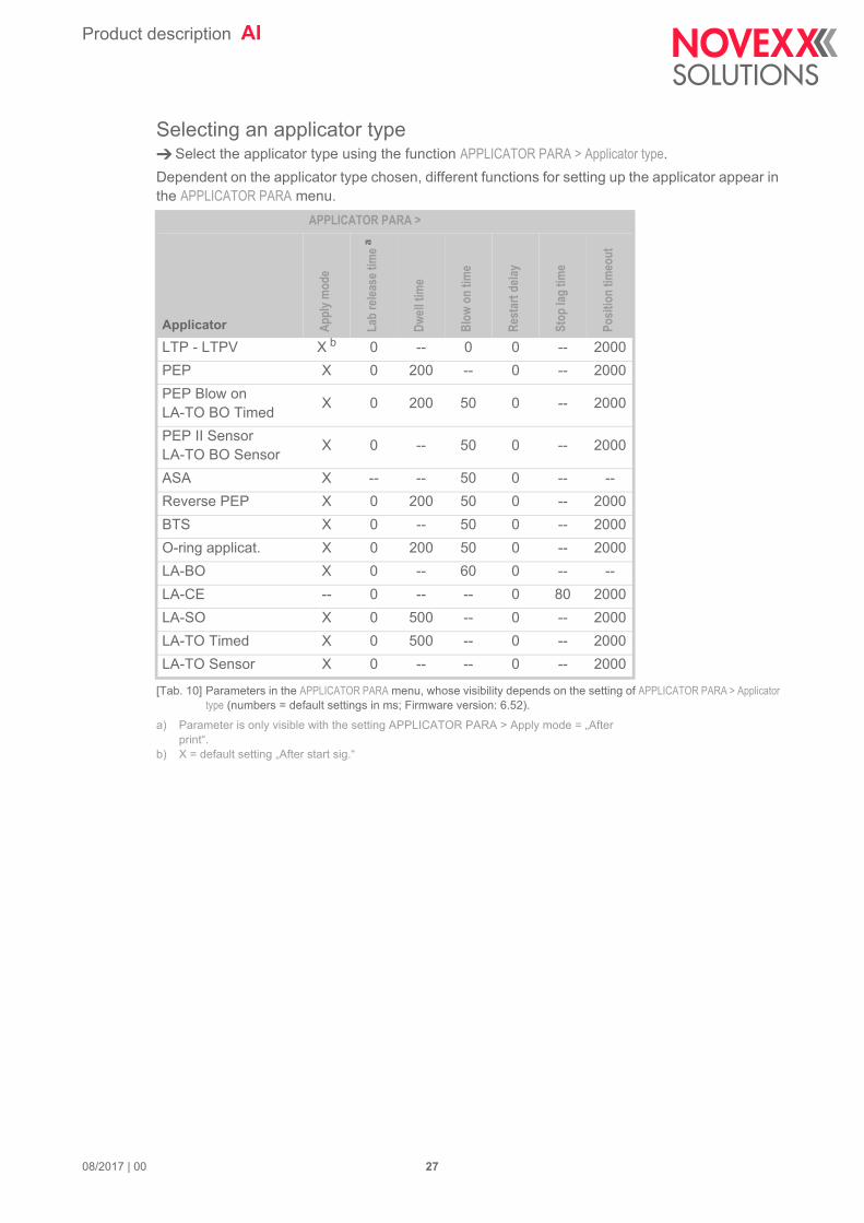
Selecting an applicator type Select the applicator type using the function APPLICATOR PARA > Applicator type.
Dependent on the applicator type chosen, different functions for setting up the applicator appear in the APPLICATOR PARA menu.
APPLICATOR PARA >
Applicator App
ly m
ode
Lab
rele
ase
time a
a) Parameter is only visible with the setting APPLICATOR PARA > Apply mode = „After print“.
Dw
ell t
ime
Blo
w o
n tim
e
Res
tart
del
ay
Stop
lag
time
Posi
tion
timeo
ut
LTP - LTPV X b
b) X = default setting „After start sig.“
0 -- 0 0 -- 2000
PEP X 0 200 -- 0 -- 2000
PEP Blow onLA-TO BO Timed
X 0 200 50 0 -- 2000
PEP II SensorLA-TO BO Sensor
X 0 -- 50 0 -- 2000
ASA X -- -- 50 0 -- --
Reverse PEP X 0 200 50 0 -- 2000
BTS X 0 -- 50 0 -- 2000
O-ring applicat. X 0 200 50 0 -- 2000
LA-BO X 0 -- 60 0 -- --
LA-CE -- 0 -- -- 0 80 2000
LA-SO X 0 500 -- 0 -- 2000
LA-TO Timed X 0 500 -- 0 -- 2000
LA-TO Sensor X 0 -- -- 0 -- 2000
[Tab. 10] Parameters in the APPLICATOR PARA menu, whose visibility depends on the setting of APPLICATOR PARA > Applicator type (numbers = default settings in ms; Firmware version: 6.52).
08/2017 | 00 27
Product description AI
SIGNAL-TIME-DIAGRAMS
Time/sensor controlled applicatorsWith time controlled applicators, extension is stopped after the setable application time run down. (APPLICATOR PARA > Dwell time).
To this applicator group belong:
• PEP IV
• PEP Blow On
• Reverse PEP
• LA-TO timed
• LA-TO BO timed
• LA-SO
With sensor controlled applicators, extension is stopped by the endposition or by the touchdown signal.
To this group belong:
• LTP(V)
• PEP II Sensor
• LA-TO sensor
• LA-TO BO sensor
08/2017 | 00 28

Product description AI
PEP IV / LA-TO timed / LA-SO
[27] Pattern of control signals over time for PEP IV, LA-TO timed and LA-SO applicators.A Duration is determined by label length and dispensing speed. „Airstream Support“ switching to low means the label
is dispensed.B Can be adjusted via APPLICATOR PARA > Dwell time. Duration t is determined by the backwards movement of the ap-
plicator. The application cycle ends when the home position signal is high again.C The output signal „Offline“ follows the input signal „Inhibit“.D The start signal is ignored because of the active „Inhibit“.
A
B
C
D
08/2017 | 00 29
Product description AI
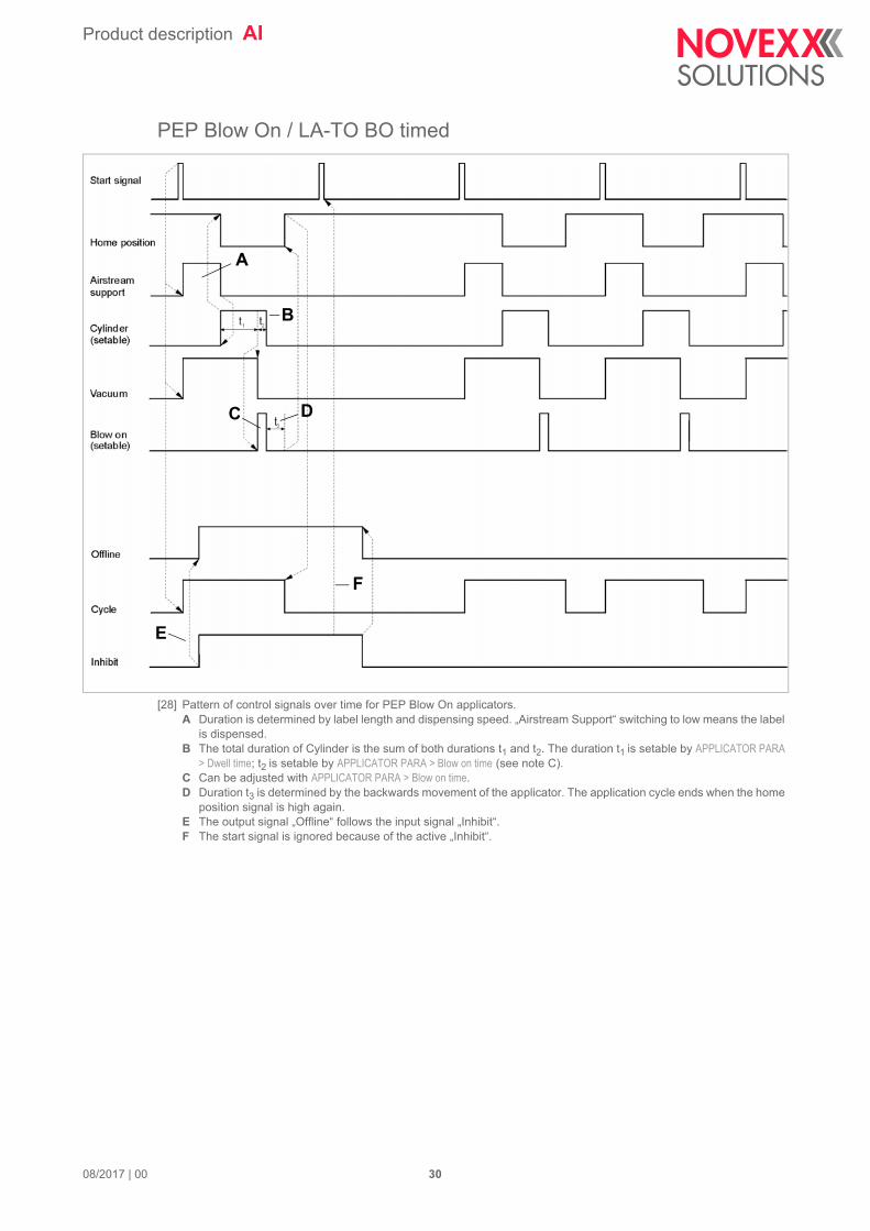
PEP Blow On / LA-TO BO timed
[28] Pattern of control signals over time for PEP Blow On applicators.A Duration is determined by label length and dispensing speed. „Airstream Support“ switching to low means the label
is dispensed.B The total duration of Cylinder is the sum of both durations t1 and t2. The duration t1 is setable by APPLICATOR PARA
> Dwell time; t2 is setable by APPLICATOR PARA > Blow on time (see note C).C Can be adjusted with APPLICATOR PARA > Blow on time.D Duration t3 is determined by the backwards movement of the applicator. The application cycle ends when the home
position signal is high again.E The output signal „Offline“ follows the input signal „Inhibit“.F The start signal is ignored because of the active „Inhibit“.
A
B
C
E
D
F
08/2017 | 00 30

Product description AI
Reverse PEP
[29] Pattern of control signals over time for Reverse PEP applicators.A Duration is determined by label length and dispensing speed. „Airstream Support“ switching to low means the label
is dispensed.B Adjustable with APPLICATOR PARA > Blow on time.C Duration t is determined by the backwards movement of the. applicator. The application cycle ends when the home
position signal is high againD The output signal „Offline“ follows the input signal „Inhibit“.E The start signal is ignored because of the active „Inhibit“.F The end of „Cycle“ can be adjusted with APPLICATOR PARA > Dwell time (usually, this function sets the end of the „Cyl-
inder“ signal, in case of the Reverse PEP, „Cylinder“ stays active up to the next start signal, what means that the dwell time is ignored).
A
B
D
C
E
F
08/2017 | 00 31

Product description AI
LTP / LTPV / LA-TO BO Sensor
[30] Pattern of control signals over time for LTP/LTPV and LA-TO BO applicators.A Duration is determined by label length and dispensing speed. „Airstream Support“ switching to low means the label
is dispensed.B Duration t is determined by the backwards movement of the applicator. The application cycle ends when the home
position signal is high againC Adjustable with APPLICATOR PARA > Blow on time.D The output signal „Offline“ follows the input signal „Inhibit“.E The start signal is ignored because of the active „Inhibit“.
t
Start signal
Home position
Airstream support
Cylinder(setable)
Vacuum
Blow on(setable)
Offline
Cycle
Inhibit
Touch downB
D
A
C
E
08/2017 | 00 32
Product description AI
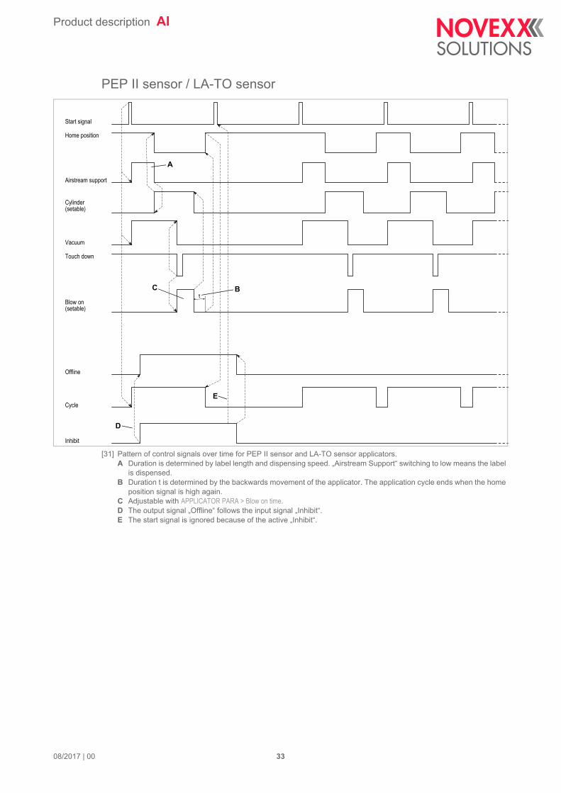
PEP II sensor / LA-TO sensor
[31] Pattern of control signals over time for PEP II sensor and LA-TO sensor applicators.A Duration is determined by label length and dispensing speed. „Airstream Support“ switching to low means the label
is dispensed.B Duration t is determined by the backwards movement of the applicator. The application cycle ends when the home
position signal is high again.C Adjustable with APPLICATOR PARA > Blow on time.D The output signal „Offline“ follows the input signal „Inhibit“.E The start signal is ignored because of the active „Inhibit“.
t
Start signal
Home position
Airstream support
Cylinder(setable)
Vacuum
Blow on(setable)
Offline
Cycle
Inhibit
Touch down
B
D
A
C
E
08/2017 | 00 33
Product description AI
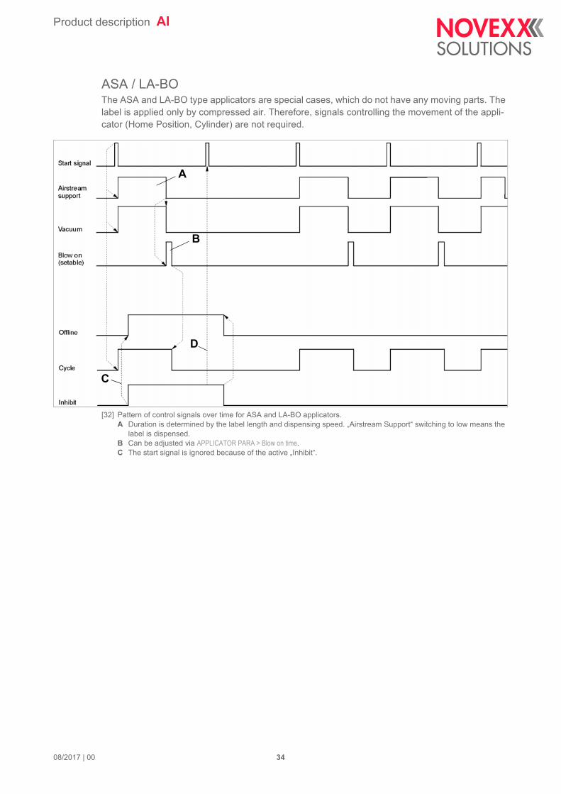
ASA / LA-BOThe ASA and LA-BO type applicators are special cases, which do not have any moving parts. The label is applied only by compressed air. Therefore, signals controlling the movement of the appli-cator (Home Position, Cylinder) are not required.
[32] Pattern of control signals over time for ASA and LA-BO applicators.A Duration is determined by the label length and dispensing speed. „Airstream Support“ switching to low means the
label is dispensed.B Can be adjusted via APPLICATOR PARA > Blow on time.C The start signal is ignored because of the active „Inhibit“.
A
B
C
D
08/2017 | 00 34


Novexx Solutions GmbHOhmstraße 385386 EchingGermany +49-8165-925-0www.novexx.com