ahsan nur mubarak zahari @ annuar
TRANSCRIPT
UNIVERSITI PUTRA MALAYSIA
AHSAN NUR MUBARAK ZAHARI @ ANNUAR
FK 2013 91
MEASUREMENT OF DIFFERENT OBSTACLES EFFECT ON RECTANGULAR CAVITY IN LOW
REYNOLDS NUMBER FLOW FIELD USING PARTICLE IMAGE VELOCIMETRY

© COPYRIG
HT UPM
`
MEASUREMENT OF DIFFERENT OBSTACLES EFFECT ON RECTANGULAR CAVITY IN LOW
REYNOLDS NUMBER FLOW FIELD USING PARTICLE IMAGE VELOCIMETRY
AHSAN NUR MUBARAK ZAHARI @ ANNUAR
MASTER OF SCIENCE UNIVERSITI PUTRA MALAYSIA
2013

© COPYRIG
HT UPM
`
MEASUREMENT OF DIFFERENT OBSTACLES EFFECT ON RECTANGULAR CAVITY IN LOW REYNOLDS NUMBER FLOW FIELD
USING PARTICLE IMAGE VELOCIMETRY
By
AHSAN NUR MUBARAK ZAHARI @ ANNUAR
Thesis submitted to the School of Graduate Studies, Universiti Putra Malaysia, In Fulfilment of the Requirement for the Degree of Master of Science
June 2013

© COPYRIG
HT UPM
`
All material contained within the thesis, including without limitation text, logos, icons, photographs and all other artwork, is copyright material of Universiti Putra Malaysia unless otherwise stated. Use may be made of any material contained within the thesis for non-commercial purposes from the copyright holder. Commercial use of material may only be made with the express, prior, written permission of Universiti Putra Malaysia. Copyright © Universiti Putra Malaysia

© COPYRIG
HT UPM
`
ii
DEDICATIONS
to both of my parents Zahari @ Annuar Bin Yahya and Che Mahani Bt. Tengku Ibrahim
to my lovely wife Nen Hasbeyah Bt. Mohamed Izazi to my son Izz Walee Mahdi B. Ahsan Nur Mubarak
© COPYRIG
HT UPM
`
iii
Abstract of thesis presented to the Senate of Universiti Putra Malaysia in fulfilment of the requirement for the Degree of Master of Science
MEASUREMENT OF DIFFERENT OBSTACLES EFFECT ON
RECTANGULAR CAVITY IN LOW REYNOLDS NUMBER FLOW FIELD USING PARTICLE IMAGE VELOCIMETRY
By
AHSAN NUR MUBARAK ZAHARI @ ANNUAR
June 2013
Chairman : Azmin Shakrine Bin Mohd Rafie, PhD
Faculty : Engineering
Flow past a cavity is a topic of great interest in the field of fluid dynamic properties.
The characteristics of the flow depend on the Reynolds number, types of boundary
layer, Mach number and the geometry of the cavity itself. Even though a large
amount of investigation has been instigated for various objectives and aspects of the
flow, the properties of dynamic flow involving cavities have yet to be fully
discovered.
Review of literature leads to the need of investigation about the effect of an obstacle
in front of a rectangular cavity. The cavity can be explained as a two-dimensional
body that would disturb the flow from upstream to downstream which
mathematically defined as loss of forces in momentum equation. The lost forces can
be described as drag which can give a significant effect in terms of flow dynamic
problem. By introducing an obstacle, the idea is to control the flow from entering
into the cavity which is the main reason of cavity drag creation.
© COPYRIG
HT UPM
`
iv
The purpose of this current experiment was to investigate the effect of six different
types of obstacle at the leading edge of a rectangular cavity in upstream laminar flow
condition with ReL = 5.12 x 10⁴. The characterization also included the changes of
cavity depth with respect to cavity length (L/D = 4, 2.29, and 1.78) and freestream
velocity within a very low speed region (V = 3.8 m/s, 4.8 m/s, and 6.5 m/s). The
findings of this current experimental result will be used in the development of
predicting fluid behaviour inside the cavity associated with this flow field.
The experiment was conducted in an open subsonic wind tunnel designed purposely
for low speed regions. The data was obtained by using 2-D Particle Image
Velocimetry (PIV). The test model was designed using transparent materials for both
flow visualization and allowing the laser sheet to pass through in experiments,
acquiring 700 image pairs for each individual experiment resulting in an overall
velocity vector.
The result was produced using a mean velocity profile that was separated into u and v
components. Analysis of the data showed that the obstacle affected the flow inside
and above the cavity. Changing the obstacle type also changes the strength of vortex
occurrence within the cavity with the triangle obstacle of 1 cm width and rectangular
obstacle of 1 cm width generated the best flow behaviour among obstacles for
differentiating the cavity depth and velocity within low Reynolds number region.
The significance of result can be used as a foundation result for further investigation
to any type of cavity with obstacles research.

© COPYRIG
HT UPM
`
v
Abstrak tesis yang dikemukakan kepada Senat Universiti Putra Malaysia sebagai memenuhi keperluan untuk Ijazah Master Sains
PENGUKURAN UNTUK KESAN PENGHALANG YANG BERBEZA KEPADA ALIRAN NOMBOR REYNOLDS YANG RENDAH PADA KAVITI
SEGIEMPAT TEPAT MENGGUNAKAN ALAT UKUR KELAJUAN GAMBAR BERPATIKEL
Oleh
AHSAN NUR MUBARAK BIN ZAHARI @ ANNUAR
Jun 2013
Pengerusi : Azmin Shakrine Bin Mohd Rafie, PhD
Fakulti : Kejuruteraan
Aliran udara melalui sebuah rongga atau kaviti ialah salah satu topik yang sangat
penting untuk penyelidikan dinamik bendalir. Ciri-ciri aliran bergantung kepada
nombor Reynolds, jenis-jenis lapisan sempadan, nombor Mach dan geometri rongga
itu sendiri. Walaupun sejumlah besar siasatan telah dijalankan untuk pelbagai
matlamat dan aspek-aspek bagi aliran, ciri-ciri aliran dinamik melibatkan rongga
belum lagi sepenuhnya diterokai.
Tujuan eksperimen yang terbaru ini ialah untuk menyiasat kesan aliran udara di
dalam rongga berbentuk segiempat tepat apabila diletakkan enam jenis penahan di
hadapan rongga segi empat tepat dalam keadaan aliran lamina dengan ReL = 5.12 x
104. Pembolehubah adalah perubahan kedalaman rongga segiempat tepat ini terhadap
panjang rongga ( L/D = 4, 2.29 , dan 1.78 ) dan halaju luar dengan kelajuan yang
sangat rendah (V = 3.8 m/s, 4.8 m/s , dan 6.5 m/s). Hasil keputusan eksperimen

© COPYRIG
HT UPM
`
vi
terkini ini akan digunakan sebagai asas ramalan tingkah laku aliran bendalir di dalam
rongga dengan berpandukan keadaan aliran yang berkaitan.
Eksperimen dijalankan di dalam satu terowong angin subsonik yang terbuka yang
dikhaskan untuk rantau kelajuan yang perlahan. Data telah diperolehi dengan
menggunakan 2-D Alat Ukur Kelajuan Gambar Berpatikel (PIV). Model untuk
eksperimen dihasilkan dengan menggunakan bahan lutsinar untuk visualisasi aliran
dan membenarkan pancaran cahaya laser melaluinya, dan cubaan sebanyak 700
gambar berpasangan-pasangan dilakukan untuk setiap eksperimen berasingan
menghasilkan satu vektor halaju.
Keputusan dibuat berdasarkan profil halaju purata dengan cara menghuraikan halaju
komponen u and v. Analisis data menunjukkan bahawa penahan memberi kesan
terhadap aliran di dalam dan di atas rongga. Perubahan jenis penahan juga
menghasilkan pusaran aliran yang mempunyai kekuatan berbeza-beza dalam rongga
dengan penahan segitiga dengan kelebaran 1 cm dan segiempat tepat dengan
kelebaran 1 cm menghasilkan aliran terbaik berbanding penahan-penahan yang lain
apabila diubah kedalaman kaviti dan halaju dalam rantau kelajuan perlahan.

© COPYRIG
HT UPM
`
vii
ACKNOWLEDGEMENT
Thank you to The Almighty, Allah S.W.T for giving me the strength and passion to complete this thesis
I would like to express my gratitude to my supervisor Dr. Azmin Shakrine Mohd Rafie for his brilliant guidance and patient in the completion of this thesis. I would
like to thank Dr. Mohamed Thariq Hameed Sultan and Prof. Ir. Dr. Shahnor Basri for their help and useful opinions throughout my research work. My experimental work
would not be completed without the help from Mr. Ropiee Mat and Mr. Saffairus Saleh, our hardworking and superb technician. I would like to thank them for the
priceless lesson and precious time for this research and life.
I am forever in debt to my dear parents. Thank you for your limitless support.

© COPYRIG
HT UPM
`
viii
I certify that a Thesis Examination Committee has met on 3rd June 2013 to conduct the final examination of Ahsan Nur Mubarak bin Zahari @ Annuar on his thesis entitled “Measurement of Different Obstacles Effect on Rectangular Cavity in Low Reynolds Number Flow Field Using Particle Image Velocimetry” in accordance with the Universities and University College Act 1971 and the Constitution of the Universiti Putra Malaysia [P.U.(A) 106] 15 March 1998. The committee recommends that the student be awarded the Master of Science.
Members of the Thesis Examination Committee were as follows:
Mohd Ramly Mohd Ajir, Lt. Col.(R) Associate Professor Faculty of Engineering Universiti Putra Malaysia (Chairman) Kamarul Arifin Ahmad, PhD Associate Professor Faculty of Engineering Universiti Putra Malaysia (Internal Examiner) Harijono Djojodihardjo, PhD, Ir Professor Faculty of Engineering Universiti Putra Malaysia (Internal Examiner) Mohd Zulkifly Abdullah, PhD Professor Universiti of Science Malaysia (External Examiner)
____________________ NORITAH OMAR, PhD Assoc. Professor and Deputy Dean School of Graduate Studies Universiti Putra Malaysia
Date:

© COPYRIG
HT UPM
`
ix
This thesis was submitted to the Senate of Universiti Putra Malaysia and has been accepted as fulfilment of the requirement for the degree of Master of Science. The members of the Supervisory Committee were as follows:
Azmin Shakrine Mohd Rafie, PhD Senior Lecturer Faculty of Engineering Universiti Putra Malaysia (Chairman) Mohamed Thariq Hameed Sultan, PhD Senior Lecturer Faculty of Engineering Universiti Putra Malaysia (Member) Shahnor Basri, PhD, Ir Professor Faculty of Mechanical Engineering Universiti Malaysia Pahang (External Member)
___________________________ BUJANG BIN KIM HUAT, PhD Professor and Dean School of Graduate Studies Universiti Putra Malaysia
Date:

© COPYRIG
HT UPM
`
x
DECLARATION
I declare that the thesis is my original work except for quotations and citations which have been properly acknowledged. I also declare that it has not been previously, and is not concurrently, submitted for any other degree at Universiti Putra Malaysia or at any other institution. Intellectual property from the thesis and copyright of thesis are fully-owned by Universiti Putra Malaysia, as according to the Universiti Putra Malaysia (Research) Rules 2012; Written permission must be obtained from supervisor and the office of Deputy Vice-Chancellor (Research and Innovation) before thesis is published (in the form of written, printed or in electronic form) including books, journals, modules, proceedings, popular writings, seminar papers, manuscripts, posters, reports, lecture notes, learning modules or any other materials as stated in the Universiti Putra Malaysia (Research) Rules 2012. There is no plagiarism or data falsification/fabrication in the thesis, and scholarly integrity is upheld as according to the Universiti Putra Malaysia (Graduate Studies) Rules 2003 (Revision 2012-2013) and the Universiti Putra Malaysia (Research) Rules 2012. The thesis has undergone plagiarism detection software.
___________________________________________ AHSAN NUR MUBARAK ZAHARI @ ANNUAR
Date: 3 June 2013

© COPYRIG
HT UPM
`
xi
TABLE OF CONTENTS
Page
DEDICATIONS ii ABSTRACT iii ABSTRAK v ACKNOWLEDGEMENT vii APPROVAL viii DECLARATION x LIST OF TABLES xiii LIST OF FIGURES xiv LIST OF NOMENCLATURES xviii
CHAPTER
1 INTRODUCTION 1 1.1 Introduction of Cavity 2 1.2 Problem Statement 5 1.3 Objectives 8 1.4 Scope of study and relevance 9 1.5 Hypothesis 11 1.6 Thesis Layout 12 2 LITERATURE REVIEW 14 2.1 Overview 14 2.2 Related Theories
2.2.1 Vectors 2.2.2 Data Analysis Theories
15 15 17
2.3 Cavity Review 2.3.1 Importance of Cavity Research 2.3.2 Cavity Geometry
18 19 21
2.4 Prior Research on Cavities 2.4.1 Drag 2.4.2 Velocity Field 2.4.3 Flow Control 2.4.4 Cavities on Airfoils 2.4.5 Others
24 24 27 32 37 40
2.5 Summary 43 3 METHODOLOGY 47 3.1 Overview 47 3.2 Description of Wind Tunnel 48 3.3 Cavity Details
3.3.1 Cavity Test Section 3.3.2 Cavity Model
3.3.3 Obstacle Model 3.3.4 Laser Rig
49 49 50 51 52
3.4 Particle Image Velocimetry (PIV) System 3.4.1 Charged Couple Device (CCD)
53 55

© COPYRIG
HT UPM
`
xii
Camera 3.4.2 Illumination System/Laser 3.4.3 FlowMap System Hub 3.4.4 Seeding Particle
56 57 58
3.5 Experimental Setup 59 3.6 Measurement Setup
3.6.1 PIV Setup 64 65
3.7 Error Analysis 3.7.1 Flow Calibration 3.7.2 Experimental Error 3.7.3 Uncertainty Analysis
71 72 74 77
4 RESULTS AND DISCUSSIONS 79 4.1 Validation result 80 4.2 Experimental result
4.2.1 Cavity L/D = 4 with V = 3.8 m/s 4.2.2 Cavity L/D = 4 with V = 4.8 m/s 4.2.3 Cavity L/D = 2.29 with V = 4.8 m/s 4.2.4 Cavity L/D = 1.78 with V = 4.8 m/s
82 83 90 96 103
4.3 Comparison of u and v-velocity component based on depth
110
4.4 Comparison of different speeds for cavity with L/D = 4
124
4.5 Summarization of Experimental Results 127
5 CONCLUSION 129 5.1 Future Work 132
APPENDIX A 134 APPENDIX B 139 REFERENCES 158 BIODATA OF STUDENT 163

© COPYRIG
HT UPM
`
xiii
LIST OF TABLES
Table Page
3.1 Dimension of obstacle 51
3.2 Image size 61
3.3 Dantec software suggestions for lower velocity 66
3.4 Example of raw data from PIV for one position of y-axis 69
3.5 Example of data extraction for u-profile of x/L = 0.1 70
3.6 Uncertainty guideline 78
4.1 Parameters for validation 80
4.2 Summarization of <u>/U result for L/D = 4 at V = 3.8 m/s 86
4.3 Summarization of <v>/U result for L/D = 4 at V = 3.8 m/s 89
4.4 Summarization of <u>/U result for L/D = 4 at V = 4.8 m/s 92
4.5 Summarization of <v>/U result for L/D = 4 at V = 4.8 m/s 96
4.6 Summarization of <u>/U result for L/D = 2.29 at V = 4.8 m/s 99
4.7 Summarization of <v>/U result for L/D = 2.29 at V = 4.8 m/s 103
4.8 Summarization of <u>/U result for L/D = 1.78 at V = 4.8m/s 106
4.9 Summarization of <v>/U result for L/D = 1.78 at V = 4.8m/s 110
4.10 Best possible obstacle for cavity with V = 4.8 m/s 127
4.11 Best possible obstacle for cavity L/D = 4 with V = 3.8 m/s 128

© COPYRIG
HT UPM
`
xiv
LIST OF FIGURES
Figure Page
1.1 Examples of cavity on vehicles 4
1.2 Control volume for obtaining drag on a two-dimensional body 6
1.3 Schematics of the Cavity 7
1.4 Scope of study 10
2.1 Different value of velocity component 16
2.2 Definition of vortex using <u>/U and <v>/U 16
2.3 Example of cavity on a truck 21
2.4 Examples of cavity geometry 23
2.5 Types of Cavity flow control 34
2.6 (a) The position of horizontal plate; (b) Types of edges
35
2.7 The position of circular cylinder 36
2.8 Geometry of one of the airfoil with a cavity
39
2.9 Types of Cavity 43
2.10 Open and Closed cavity 44
3.1 Hampden Wind Tunnel Model H-6910 CDL 48
3.2 Cavity Test Section 49
3.3 Cavity Model and Obstacle Position at Leading Edge 50
3.4 Types of Obstacle 51
3.5 Laser Rig (a) Inertial design (b) Completed design 52
3.6 2-D PIV Principle 54
3.7 Kodak Megaplus Camera Model ES1.0 55
3.8 Nd:YAG New Wave Solo Laser 56

© COPYRIG
HT UPM
`
xv
3.9 Control panel layout 57
3.10 SAFEX Fog Generator 2010 58
3.11 PIV system experimental setup 60
3.12 (a) Calibration plate; (b) Marking the centre point 61
3.13 Research Flow Chart 63
3.14 The data flow in PIV system 64
3.15 Project arrangement 65
3.16 Example of Data from PIV 67
3.17 The defined position of streamwise location, x/L 70
3.18 PIV method flow chart 71
3.19 Pitot tube locations 73
3.20 Averaged pressure graph 73
3.21 Example of pressure calibration measurement 74
4.1 Validation graph compared with Grace et al. (2004) 80
4.2 Comparison with Grace et al. (2002) at a) x/L = 0.1; b) x/L = 0.2
81
4.3 <u>/U for cavity L/D = 4 at x/L = 0.1, V = 3.8 m/s 83
4.4 <u>/U for cavity L/D = 4 at x/L = 0.25, V = 3.8 m/s 83
4.5 <u>/U for cavity L/D = 4 at x/L = 0.5, V = 3.8 m/s 84
4.6 <u>/U for cavity L/D = 4 at x/L = 0.75, V = 3.8 m/s 84
4.7 <v>/U for cavity L/D = 4 at x/L = 0.1, V = 3.8 m/s 86
4.8 <v>/U for cavity L/D = 4 at x/L = 0.25, V = 3.8 m/s 87
4.9 <v>/U for cavity L/D = 4 at x/L = 0.5, V = 3.8 m/s 87
4.10 <v>/U for cavity L/D = 4 at x/L = 0.75, V = 3.8 m/s 88
4.11 <u>/U for cavity L/D = 4 at x/L = 0.1, V = 4.8 m/s 90
4.12 <u>/U for cavity L/D = 4 at x/L = 0.25, V = 4.8 m/s 90

© COPYRIG
HT UPM
`
xvi
4.13 <u>/U for cavity L/D = 4 at x/L = 0.5, V = 4.8 m/s 91
4.14 <u>/U for cavity L/D = 4 at x/L = 0.75, V = 4.8 m/s 91
4.15 <v>/U for cavity L/D = 4 at x/L = 0.1, V = 4.8 m/s 93
4.16 <v>/U for cavity L/D = 4 at x/L = 0.25, V = 4.8 m/s 93
4.17 <v>/U for cavity L/D = 4 at x/L = 0.5, V = 4.8 m/s 94
4.18 <v>/U for cavity L/D = 4 at x/L = 0.75, V = 4.8 m/s 94
4.19 <u>/U for cavity L/D = 2.29 at x/L = 0.1, V = 4.8 m/s 96
4.20 <u>/U for cavity L/D = 2.29 at x/L = 0.25, V = 4.8 m/s 97
4.21 <u>/U for cavity L/D = 2.29 at x/L = 0.5, V = 4.8 m/s 97
4.22 <u>/U for cavity L/D = 2.29 at x/L = 0.75, V = 4.8 m/s 98
4.23 <v>/U for cavity L/D = 2.29 at x/L = 0.1, V = 4.8 m/s 100
4.24 <v>/U for cavity L/D = 2.29 at x/L = 0.25, V = 4.8 m/s 100
4.25 <v>/U for cavity L/D = 2.29 at x/L = 0.5, V = 4.8 m/s 101
4.26 <v>/U for cavity L/D = 2.29 at x/L = 0.75, V = 4.8 m/s 101
4.27 <u>/U for cavity L/D = 1.78 at x/L = 0.1, V = 4.8 m/s 103
4.28 <u>/U for cavity L/D = 1.78 at x/L = 0.25, V = 4.8 m/s 104
4.29 <u>/U for cavity L/D = 1.78 at x/L = 0.5, V = 4.8 m/s 104
4.30 <u>/U for cavity L/D = 1.78 at x/L = 0.75, V = 4.8 m/s 105
4.31 <v>/U for cavity L/D = 1.78 at x/L = 0.1, V = 4.8 m/s 107
4.32 <v>/U for cavity L/D = 1.78 at x/L = 0.25, V = 4.8 m/s 107
4.33 <v>/U for cavity L/D = 1.78 at x/L = 0.5, V = 4.8 m/s 108
4.34 <v>/U for cavity L/D = 1.78 at x/L = 0.75, V = 4.8 m/s 108
4.35 Comparison of <u>/U profile for WB 111
4.36 Comparison of <v>/U profile for WB 111
4.37 Comparison of <u>/U profile for TRI1 112
© COPYRIG
HT UPM
`
xvii
4.38 Comparison of <v>/U profile for TRI1 113
4.39 Comparison of <u>/U profile for REC1 114
4.40 Comparison of <v>/U profile for REC1 115
4.41 Comparison of <u>/U profile for HC1 116
4.42 Comparison of <v>/U profile for HC1 117
4.43 Comparison of <u>/U profile for TRI2 118
4.44 Comparison of <v>/U profile for TRI2 119
4.45 Comparison of <u>/U profile for REC2 120
4.46 Comparison of <v>/U profile for REC2 121
4.47 Comparison of <u>/U profile for HC2 122
4.48 Comparison of <v>/U profile for HC2 123
4.49 Comparison of <u>/U at different speed for cavity with L/D = 4 125
4.50 Comparison of <v>/U at different speed for cavity with L/D = 4 125

© COPYRIG
HT UPM
`
xviii
LIST OF NOMENCLATURES
Symbols
L Length m
h height m
d Depth m
f frequency s-1
u Streamwise velocity m/s
v Normal velocity m/s
uv Mean momentum transfer
''vu Reynolds Stress
Ma Mach number
Re Reynolds number
V Freestream velocity m/s
<u> Mean streamwise velocity m/s
<v> Mean normal velocity m/s
L/D Length-to-depth ratio of cavity
x Streamwise distance m
y Vertical distance m
Greek
θ Momentum thickness m
ρ Density kg/m3
y
u Viscous Stress
Π Pi

© COPYRIG
HT UPM
`
xix
Circulation
Subscript
h height/depth of cavity m
L Length of cavity m
d depth of cavity m
e excitation of frequency
s shear stress
Abbreviations
PIV Particle Image Velocimetry
CFD Computational Fluid Dynamics
RANS Reynolds Averaged Navier Stokes
WB Cavity without obstacle
TRI1 Cavity with 1 cm length of triangle obstacle
REC1 Cavity with 1 cm length of rectangular obstacle
HC1 Cavity with 1 cm length of half-cylinder obstacle
TRI2 Cavity with 2 cm length of triangle obstacle
REC2 Cavity with 2 cm length of rectangular obstacle
HC2 Cavity with 2 cm length of half-cylinder obstacle

© COPYRIG
HT UPM
`
xx

© COPYRIG
HT UPM
`
1
CHAPTER 1
INTRODUCTION
Transportation is one of the most common topics among researchers. Air, land, and
water transportation have unlimited potential for progress to achieve an optimum
design for maximum benefit. Improving fuel consumption is one of the highlights for
recent research aside from rate of performance for certain transport such as aircraft,
cars, and others.
Many aspects need to be observed like the types of transport, the shape, power
consumption and many more but one of the problem factors that all transportation
face is the flow dynamics problem. Developing a new transportation design that can
reduce fuel consumption and drag is one of the chosen criteria. According to Bertin
(2002), flow control can save fuel by around 27 – 30 % for aircraft. It was well noted
how important it is to get the best flow control for any kind of transportation.
All transportation must face the flow dynamics problem whether on solid surface like
on land or fluid such as air and water. The mechanism is different but the effect is
quite the same for aerodynamics or hydrodynamics. Even though there are
advantages and disadvantages for the effect of flow, but for some reason, the flow
must be controlled to get what is needed most. All designers and aircraft engineers

© COPYRIG
HT UPM
`
2
aim to build the fastest and the most fuel efficient design. One of the answers is lying
in this current research.
Flow dynamics problem always occur on the surface region. There must be some
imperfections on the surface that are known as surface irregularities. Most surface
irregularities are caused by manufacturing or design constraints for different
vehicles. They cannot be removed completely but only can be adjusted to get the best
aerodynamic effect. In flight for example, these include landing gear wells, weapon
bays, and other aircraft grooves. Meanwhile, for land or water transport, these
include sunroof window, side window, gap between truck and its body, and many
more applications. These surface irregularities will increase the defection of flow and
all of those surface irregularities can be described as cavity.
1.1 Introduction of Cavity
Since the early 1930’s, the study of flow regarding with cavity had been investigated
worldwide. As mentioned by Hoerner (1965), the investigation of any surface
irregularities were highly recommended as to reduce overall drag or fuel
consumption for achieving new development in the transportation industry especially
for aircraft.

© COPYRIG
HT UPM
`
3
According to McGregor and White (1970), a cavity can be described as anything that
looks like a gap, cut-out, notch, or groove on the surface that has both borders at its
leading and trailing edge. In early investigations on cavities, researchers realised that
although the geometry of a cavity was simple, the complexity of flow behaviour
inside a cavity was tremendously difficult to understand because it not only
depended on the shape of the cavity but also on the upstream approaching types of
flow, variation in speed, and boundary layer. As concluded by Gaudet and Winter
(1973), it is unlikely to produce a simple analysis method for describing the possible
combinations of flow pattern inside a hole (cavity) because of its complexity.
A cavity can cause many effects that need to be understood deeply further which
generates wanted and unwanted flow behaviour in real applications. Although most
of the cavity effects are considered as bad factors, some other applications look the
other way round. The easiest example for using the advantages of cavity effects is a
vortex generator. Kuethe and Chow (1986) mentioned that vortex generators are used
as a tool to reduce flow separation on airfoils by increasing the flow attachment on
the surface. One type of vortex generator is called a cavity vortex generator and
among the famous institutions that are involved with cavity effect is NASA for the
supersonic flow region as reported by Hazlewood (1996).
© COPYRIG
HT UPM
`
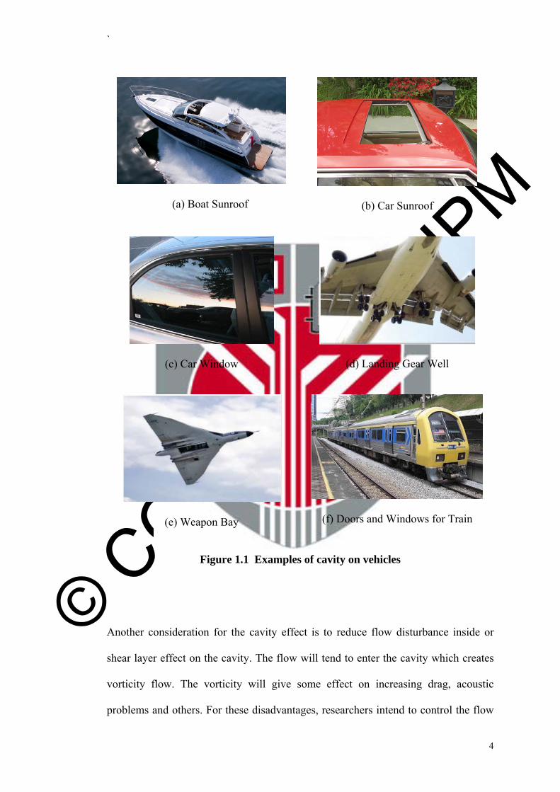
4
(a) Boat Sunroof
(b) Car Sunroof
(c) Car Window
(d) Landing Gear Well
(e) Weapon Bay
(f) Doors and Windows for Train
Figure 1.1 Examples of cavity on vehicles
Another consideration for the cavity effect is to reduce flow disturbance inside or
shear layer effect on the cavity. The flow will tend to enter the cavity which creates
vorticity flow. The vorticity will give some effect on increasing drag, acoustic
problems and others. For these disadvantages, researchers intend to control the flow
© COPYRIG
HT UPM
`
5
inside the cavity to reduce the occurrence of vortices which is the area of study of the
current research.
From the general information, knowing the importance and the behaviour of flow
inside a cavity is essential to design the best aircraft or any vehicles. Many
researchers understand these perfectly and give their effort pushing to their limit to
gather as much information about it as possible. They have been going detail by
detail in each part and component which is meaningless to people who cannot
understand the beauty of aerodynamics.
1.2 Problem Statement
Since the earliest development in researching cavity problems in fluid mechanics, the
main focus has been already identified which is to reduce the drag as much as
possible. Many kinds of ways have been conducted even as today. All of them tried
to push the limit to reduce the vortices inside a cavity. The main goal, which has not
changed to this day, is to increase the performance of aircraft or other vehicle to its
maximum. There are many ways to increase the performance of aircraft, and they are
willing to investigate parts by parts, region by region as thoroughly as possible. One
of the regions is cavities.
© COPYRIG
HT UPM
`
6
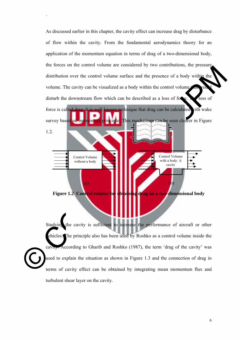
As discussed earlier in this chapter, the cavity effect can increase drag by disturbance
of flow within the cavity. From the fundamental aerodynamics theory for an
application of the momentum equation in terms of drag of a two-dimensional body,
the forces on the control volume are considered by two contributions, the pressure
distribution over the control volume surface and the presence of a body within the
volume. The cavity can be visualized as a body within the control volume that would
disturb the downstream flow which can be described as a loss of force. The loss of
force is called drag. It is well known technique that drag can be calculated with wake
survey based on momentum principle. This mechanism can be seen clearer in Figure
1.2.
(a)
(b)
Figure 1.2 Control volume for obtaining drag on a two-dimensional body
Studying the cavity is sufficient to increase the performance of aircraft or other
vehicles. The principle also has been used by Roshko as a control volume inside the
cavity. According to Gharib and Roshko (1987), the term ‘drag of the cavity’ was
used to explain the situation as shown in Figure 1.3 and the connection of drag in
terms of cavity effect can be obtained by integrating mean momentum flux and
turbulent shear layer on the cavity.
Control Volume with a body: A
cavity
Control Volume without a body

© COPYRIG
HT UPM
`
7
Figure 1.3 Schematics of the cavity
(Source: M. Gharib and A. Roshko,1987)
Cavity drag was created more on momentum flux and shear layer effect and this can
be investigated basically by using flow velocity field as mentioned by Gharib and
Roshko (1987) to get the assumption of vortex occurrence and strength in the cavity.
Even though a cavity is always related to increasing of drag, some research also has
the opposite opinion which is that cavities can help the performance of an aircraft
wing in certain conditions by reducing separation wake flow as the flow in the cavity
can enhance the performance of airfoils at certain angles of attack.
For real applications as shown in Figure 1.1, there was an obstacle in front of the
cavity like at a car window, train and none for an aircraft weapon bay. These
obstacles are already there and seem to have positive effects on the cavity flow or
may be able to produce some kind of flow control mechanism for the cavity as
suggested by Rossiter (1964).

© COPYRIG
HT UPM
`
8
Therefore, an experiment was made to establish the effect of obstacle on the cavity
flow as a form of passive flow control with the limitation of low Reynolds number
and upstream laminar flow region. The pressure will not be investigated for this
experiment, observing only the changes of velocity field inside the cavity related to
the prediction of vortices behaviour.
1.3 Objectives
Generally, the objective was to investigate flow behaviour in the rectangular cavity
by using a Particle Image Velocimetry (PIV) measurement system. Specific
objectives for the current research work were made to comply with the problem
statement previously. The objectives are as follows:
a) To investigate the effect of rectangular cavity depth for L/D = 4, 2.29 and 1.78
by flow velocity around 4.8m/s with corresponding Reynolds number, ReL =
5.12 x 10⁴ based on cavity length.
b) To investigate the effect of obstacles at the leading edge of rectangular cavity of
L/D = 4, 2.29 and 1.78 by flow velocity around 4.8m/s.
c) To investigate the effect of different speed at 3.8 m/s, 4.8 m/s and 6.5 m/s for
rectangular cavity with L/D = 4.

© COPYRIG
HT UPM
`
9
1.4 Scope of Study and Relevance
The scope of study for this research is the effect of a cavity as one of the surface
irregularities on the body in terms of flow behaviour. The current work involves six
different of obstacles at the leading edge of the cavity with different depths. The
existence of a cavity on the surface, also referred to as cut-out surface, will change
the flow pattern on the surface and allow the flow to go through inside the cavity
which can enhance the effect. Therefore, passive flow control has been used by
putting the obstacle that will perturb the incoming flow and reduce the possibility of
vortices creation inside the cavity.
The existence of obstacles in front of cavity-like surfaces on vehicles is very
common especially for cars, trucks, trains and motorboats. Doors and windows on
vehicles are always designed with an obstacle-like shape in front, and the tops of
trucks also have an obstacle-like design but the need in having the best obstacle and
to understand deeper about the effect of existing obstacle in front of the cavity is a
requirement to enhance the performance of those vehicles.
Currently, there is no information regarding of the effect of obstacle in terms of a
rectangular shallow cavity effect with very low Reynolds number. Hence, this
research will focus on its effect by using present techniques and approach of flow
characteristic experiment. The configuration of cavity design for the current research

© COPYRIG
HT UPM
`
10
was a rectangular shape with differing length-to-depth ratios (L/D) of 4, 2.29 and
1.78.
The cavity Reynolds number was set at approximately 5.12 x 10⁴ based on cavity
length while the speed involved is 4.8 m/s. These design parameters were taken into
consideration based on literature from previous work done by other researchers in
this field of study like Grace et al. (2004). Another two speeds were involved for L/D
= 4 without obstacle just to strengthen the result. These speeds were 3.8 m/s and 6.5
m/s as to compare different speed in the same region of very low Reynolds number.
Figure 1.3 Scope of study

© COPYRIG
HT UPM
`
11
For obstacle parameters, there was no information from previous researchers during
the period of study. Thus, the parameters had been decided by using logical
assumptions based on how to control the flow going inside the cavity and to reduce
the flow separation because of the obstacle itself. The experiment involved
specifically only on flow visualization and the data was based on u and v-velocity
profile, nothing mentioned on pressure distribution, noise problems and any other
data. These are the limitations and the scope of study for the current research work.
Figure 1.3 above illustrates the summary for the scope of study.
1.5 Hypothesis
The main objective for the research was to investigate the effect of varying obstacles
at the leading edge of cavity such as a triangle or half-cylinder shape on flow
behaviour inside the cavity. Hypothetically, by having an obstacle in front of the
cavity, the flow will be disturbed which can reduce the possibility of vortex
formation inside the cavity. Rossiter (1964) suggested that adding a small spoiler can
suppress the magnitude of periodic pressure fluctuation for a cavity with L/D = 1.
From this information, logically, any disturbance that is located in front of a cavity
will prevent the flow to come inside. The larger the obstacle, the lesser the flow
would go inside the cavity but it must not be large enough as to reduce any
increasing drag force outside the cavity.
This research also investigated several cavity depths with and without obstacle at the
leading edge. As a hypothesis, the depth of cavity also affects the flow behaviour

© COPYRIG
HT UPM
`
12
inside the cavity and will change for any result in each obstacle. These results will
enhance the conclusion for each obstacle case regarding two main variables, which
are obstacle and cavity depth.
This work also tested the effect of speed for one selected cavity depth without
obstacle. Making minor changes in speed, the prediction is that this would not have
any obvious effect on the flow inside the cavity. However, the empirical data must be
taken before any conclusion is made.
1.6 Thesis Layout
This section describes the thesis layout. There are five chapters involved for this
investigation, including Chapter 1, which is this introduction. Chapter 2 involves
previous research and the state of the art of this work. Chapter 3 provides the details
about the experimental methodology. Chapter 4 shows the results and discussion and
Chapter 5 summarizes the result.
In Chapter 1, there would be a general information of the importance of current
research work which covers a brief history for the cavity investigation and the
requirement needed. Real application also included as a breafing knowledge of usage
about cavity. The problem statement and objectives were included to emphasis the
current work.

© COPYRIG
HT UPM
`
13
Chapter 2 is the literature review section of the thesis. Prior research that has been
done regarding cavities were summarized into several topics. Types of cavities that
have been observed and some explainations about them have been introduced briefly.
The justification of presenting the current work has been included in this chapter.
For Chapter 3, the methodology which was employed in the experiment and
processing data is discussed. All the processes and experimental setup involved in
developing the current research has been described thoroughly. The method for
obtaining and processing the data from Particle Image Velocimetry (PIV) is
explained step by step. The uncertainty analysis is included later in this chapter.
Chapter 4 is the main emphasis of the thesis which gathers all the data involved in
the experiments. The results that had been taken from the experimental process were
analyzed, presented, and discussed in detail. The data was the summarization of
velocity field data obtained from PIV and had been interpreted in graphs for certain
sections. Comparisons had been made for all obstacles and different L/D.
Chapter 5 provides the conclusion of the results and the limitations involved in the
project. Future work recomendations were made and proposed based on the
empirical results that had been previously discussed in proper.
© COPYRIG
HT UPM
`
158
REFERENCES
Anderson Jr., J. D. (2007). Fundamental of Aerodynamics (Fourth Edition ed.): Mc Graw Hill.
Ashcroft, G., & Zhang, X. (2005). Vortical Structures Over Rectangular Cavities At Low Speed. Physics of Fluids, 17(015014).
Ashok, A., Ragni, D., W. van Oudheusden, B., & Scarano, F. (2008). PIV-based Surface Pressure and Aerodynamic Loads Determination On A Transonic Airfoil. EWA International Workshop, Delft, Netherlands, 31st March to 1st April 2008.
Barlow, J. B., Rae Jr., W. H., & Pope, A. (1999). Low Speed Wind Tunnel Testing: John Wiley & Sons, Inc.
Bertin, J. J. (2002). Aerodynamics for engineers (4th ed.): Prentice Hall, Inc.
Brés, G. A., & Colonius, T. (2008). Three-dimensional instabilities in Compressible Flow Over Open Cavities. Journal of Fluid Mechanics, 599, 309-339.
Cabell, R. H., Kegerise, M. A., Cox, D. E., & Gibbs, G. P. (2002). Experiment feedback control of flow induced cavity tones. AIAA Paper(2002-2497).
Camussi, R., Guj, G., Di Marco, A., & Ragni, A. (2006). Propagation of wall pressure pertubations in a large aspect ratio shallow cavity. Experiment in Fluids, 40, 612-620.
Cattafesta III, L. N., Song, Q., Williams, D. R., Rowley, C. W., & Alvi, F. S. (2008). Active Control of Flow-Induced Cavity Oscillations. Progress of Aerospace Sciences, 44, 479-502.
Chatellier, L., Laumonier, J., & Gervais, Y. (2004). Theoretical and Experimental Investigations of Low Mach Number Turbulent Cavity Flows. Experiment in Fluids, 36, 728-740.
Choi, H.-I., Mun, P.-U., & Kim, J.-S. (2009). Numerical Analysis of The Subsonic Flow Around A Three-Dimensional Cavity. Journal of Mechanical Science and technology, 23, 1702-1709.
Colonius, T., Basu, A. J., & Rowley, C. W. (1999). Numerical Investigation of The Flow Past A Cavity. AIAA Paper 99-1912, 5th AIAA/CEAS Aeroacoustics Conference.
Debiasi, M., Yan, P., Little, J., Ozbay, H., Myatt, J., & Sammy, M. (2004). An Experimental Study of Subsonic Cavity Flow - Physical Understanding and Control. 2nd AIAA Flow Control Conference(AIAA-2004-2123).

© COPYRIG
HT UPM
`
159
DeGraaff, D. B. (1999). Reynolds number scaling of the turbulent boundary layer on a flat plate and on swept and unswept bumps. Stanford University.
Dewar, W. G. (2002). Experimental investigation of the flow characteristics within a shallow wall cavity for both laminar and turbulent upstream boundary layers. Boston University.
Dolling, D. S., Perng, S. W., & Leu, Y. L. (1998). An experimental study of passive control of hypersonic cavity flow oscillations. Unpublished Final Report, University of Texas.
Esteve, M. J., Reulet, P., & Millan, P. (2000). Flow Field Characterisation Within A Rectangular Cavity. Paper presented at the 10th International Symposium on the Applications of Laser Technology to Fluid Mechanics.
FlowManager Software and Introduction to PIV Instrumentation Software User's Guide. Dantec Dynamics.
Gaudet, L., & Winter, K. G. (1973). Measurement of the drag of some characteristic aircraft excrescences immersed in turbulent boundary layers. R.A.E Technical Memorandum Aero.
Gharib, M., & Roshko, A. (1987). The Effect of Flow Oscillations on Cavity Drag. Journal of Fluid Mechanics, 177, 501-530.
Grace, S. M., Dewar, W. G., & Wroblewski, D. E. (2004). Experimental Investigation of The Flow Characteristics Within A Shallow Wall Cavity for Both Laminar and Turbulent Upstream Boundary Layers. Experiment in Fluids, 36, 791-804.
Haigermoser, C., Scarano, F., & Onorato, M. (2008). Investigation of The Flow In A Rectangular Cavity Using Tomographic and Time-Resolved PIV. 26th International Congress of The Aeronautical Sciences.
Haigermoser, C., Vesely, L., Asteggiano, F., Dioguardi, M., Seracchioli, G., & Onorato, M. (2007). Time Resolved Velocity and Pressure in A Cavity Flow. Meccanica Dei Fluidi.
Hall, M. S., & Griffin, O. M. (1993). Vortex Shedding and Lock-On in a Pertubed Flow. ASME Journal of Fluid Engineering, 115, 283-291.
Hammache, M., & Browand, F. (2004). On the aerodynamics of tractor-trailers. Applied and Computational Mechanics, 19, 185-205.
Hazlewood, R. (1996). An Investigation of Cavity Vortex Generators in Supersonic Flow. NASA Report(198202).

© COPYRIG
HT UPM
`
160
Hoerner, S. F. (1965). Fluid-dynamic drag: practical information on aerodynamic drag and hydrodynamic resistance, Available from http://books.google.com.my/books?id=abU8AAAAIAAJ
Howell, R. H. (1968). Drag Forces of Two-dimensional V Shaped Notches in Transonic and Supersonic Turbulent Flow. Unpublished Ph.D Thesis, University of Illinois,, Urbana.
Jackson, A. P., Hillier, R., & Soltani, S. (2001). Experimental and Computational Study of Laminar Cavity Flows at Hypersonic Speeds. Journal of Fluid Mechanics, 427, 329-358.
Koenig, K., & Roshko, A. (1985). An Experimental Study of Geometrical Effect on The Drag and Flow Field of Two Bluff Bodies Separated by A Gap. Journal of Fluid Mechanics, 156, 167-204.
Kuethe, A. M., & Chow, C.-Y. (1986). Foundations of Aerodynamics - Bases of Aerodynamics Design (4th ed.): John Wiley & Sons, Inc.
Kuo, C.-H., & Huang, S.-H. (2003). Effect of Surface Mounting of upper Plate on Oscillating Flow Structure Within Cavity. Experimental Thermal and Fluid Sciences, 27, 755-768.
Kuo, C.-H., Huang, S.-H., & Chang, C.-W. (2000). Self-sustained Oscillation Induced by Horizontal Cover Plate Above Cavity. Journal of Fluid and Structures, 14, 25-48.
Kuo, C.-H., & Jeng, W. I. (2003). Lock-on Characteristics of a Cavity Shear Layer. Journal of Fluid and Structures, 18, 715-728.
L.-Ping, J., Cong, W., Y.-Jie, W., H.-Bin, W., J.-Zhong, Z., & K.-Ping, Y. (2006). Numerical Simulation of Artificial Ventilated Cavity. Journal of Hydrodynamics, Ser.B. 18(3), 273-279.
Lang, A. W., & Johnson, T. J. (2010). Drag Reduction Over Embedded Cavities in Couette Flow. Mechanics Research Communication, 37, 432-435.
Lawrie, D., Nayyar, P., Badcock, K., Barakos, G., & Richards, B. (2003). CFD Study of Cavity Flows. CEAS Aerospace Aerodynamics Research Conference.
Manovski, P., Giacobello, M., & Soria, J. (2007). Particle Image Velocimetry Measurement Over an Aerodynamically Open 2-Dimensional Cavity. Paper presented at the 16th Australasian Fluid Mechanics Conference.
Martinez, M., & Onorato, M. (2009). Cavity Flow Control by a Rod in Crossflow. Atti Sc. Fis. , 143, 55-65.

© COPYRIG
HT UPM
`
161
McGregor, O. W., & White, R. A. (1970). Drag of Rectangular Cavities in Supersonic and Transonic Flow Including the Effect of Cavity Resonance. AIAA Journal, 1959-1965.
Murray, N., Sallstrom, E., & Ukeiley, L. (2009). Properties of Subsonic Open Cavity Flow Fields. Physics of Fluids, 21(095103).
Olsman, W. F. J., & Colonius, T. (2011). Numerical Simulation of Flow over an Airfoil with a Cavity. AIAA Journal, 49(No. 1), 143--149.
Olsman, W. F. J., Willems, J. F. H., Hirschberg, A., Colonius, T., & Trieling, R. R. (2011). Flow around a NACA0018 airfoil with a cavity and its dynamical response to acoustic forcing. Experiment in Fluids, 51, 493-509.
Özsoy, E., Rambaud, P., Stitou, A., & Riethmuller, M. L. (2005). Vortex Characteristics in Laminar Cavity Flow at Very Low Mach Number. Experiments in Fluids, , 38, 133-145.
Pengra, D. B., & Dillman, L. T. (2009). Notes on Data Analysis and Experimental Uncertainty.Unpublished manuscript.
Plesset, M. S., & Shaffer Jr., P. A. (1948). Cavity Drag In Two and Three Dimensions. Journal of Applied Physics, 19, 934-939.
Ritchie, S. A., & Knowles, K. (2005, 5-6 September). Characterisation of a 3D l/h = 5 rectangular cavity flowfield using experimental and numerical techniques. Paper presented at the 2nd International Symposium on Integrating CFD and Experiments in Aerodynamics Cranfield University (Shrivenham)
Ritchie, S. A., Lawson, N. J., & Knowles, K. (2004). A PIV and CFD Investigation of Cavity Flows in The Transonic Flow Regime. 24th International Congress of The Aeronautical Sciences.
Roshko, A. (1955). Some Measurements of Flow In A Rectangular Cutout. NACA Technical Note, 3488.
Rossiter, J.E. (1964). Wind-Tunnel Experiment on the Flow over Rectangular Cavities at Subsonic and Transonic Speeds. ARC-R&M-3438.
Rowley, C. W., & Williams, D. R. (2006). Dynamics and Control of High-Reynolds-Number Flow over Open Cavities. Annual Review Fluid Mechanics, 38, 251-276.
Sarohia, V. (1977). Experimental investigation of oscillations in flows over shallow cavities. AIAA Journal, 15(7), 501-530.
Savory, E., Toy, N., Peter J. Disimile, P., & G. Dimicco, R. (1993). The Drag Of Three Dimensional Rectangular Cavity. Applied Scientific Research, 50, 325-346.

© COPYRIG
HT UPM
`
162
Schumacher, K., Doolan, C., & Kelso, R. (2010). Rectangular and Modified Two-Dimensional Cavities in an Open-Jet Anechoic Wind Tunnel at Low Mach number. 17th Australasian Fluid Mechanics Conference.
Solo PIV Nd: YAG Laser System Operator's Manual. (2003). New Wave Research.
Stallings, R. L. (1995). "Measurements of store forces and moments and cavity pressures for a generic store in and near a box cavity at subsonic and transonic speeds": NASA TM-4611, NASA.
Tracy, M. B., Plentovich, B., & Chu, J. (1992). Measurement of Fluctuating Pressure in a Rectangular Cavity in Transonic Flow at High Reynold Numbers. Technical Memorandum NASA 4363.
Ukeiley, L., & Murray, N. (2005). Velocity and Surface Pressure Measurement in An Open Cavity. Experiment in Fluids, 38, 656-671.
Verdugo, F. R., Guitton, A., & Camussi, R. (2012). Experimental Investigation of A Cylindrical Cavity in A Flow Mach Number Flow. Journal of Fluid and Structures, 28, 1-19.
Woo, C.-H., Kim, J.-S., & Lee, K.-H. (2008). Three-dimensional Effects of Supersonic Cavity Flow Due to The Variation of Cavity Aspect Ratio and Width Ratios. Journal of Mechanical Science and Technology, 22, 590-598.
Yaakub, M. F., Wahab, A. A., Abdul Ghafir, M. F., Mohd Yunos, S. N. M., Mohd Salleh, S. J. M., Kamarudin, Q. E., et al. (2012). The aerodynamics investigation of vortex trap on helicopter blade. Applied Mechanics and Materials, 225, 43-48.