agrément certificate 17/5447 sps envirowall external …...page 2 of 27 regulations in the opinion...
TRANSCRIPT

Page 1 of 27
SPS Envirowall Ltd
Orchard House Aire Valley Business Centre Keighley Yorkshire BD21 3DU
Tel: 01535 661633 Fax: 01535 661633 Agrément Certificate e-mail: [email protected] 17/5447 website: www.envirowall.co.uk Product Sheet 2
SPS ENVIROWALL EXTERNAL WALL INSULATION SYSTEMS SPS ENVIROWALL EXTERNAL WALL INSULATION SYSTEM (EPS)
CAVITY SYSTEM FOR TIMBER-FRAMED BUILDINGS
This Agrément Certificate Product Sheet(1) relates to the SPS Envirowall External Wall Insulation System (EPS) for Timber-Framed Buildings, comprising: EPS insulation boards, mechanically fixed to rail profiles; a reinforced basecoat; and render finishes. The system is suitable for use on the outside of sheathed timber-framed buildings in new and existing domestic and non-domestic buildings up to 18 m.
(1) Hereinafter referred to as ‘Certificate’.
CERTIFICATION INCLUDES: • factors relating to compliance with Building Regulations
where applicable • factors relating to additional non-regulatory information
where applicable • independently verified technical specification • assessment criteria and technical investigations • design considerations • installation guidance • regular surveillance of production • formal three-yearly review.
KEY FACTORS ASSESSED Thermal performance — the system can be used to improve the thermal performance of external walls and can contribute to satisfying the requirements of the national Building Regulations (see section 6).
Strength and stability — the system can adequately resist wind loads and impact damage. The impact resistance is dependent on the finish chosen (see section 7).
Behaviour in relation to fire — the system has a B-s1, d0 reaction to fire classification in accordance with BS EN 13501-1 : 2007 (see section 8).
Risk of condensation — the system can contribute to limiting the risk of interstitial and surface condensation (see section 11).
Durability — when installed and maintained in accordance with the Certificate holder’s recommendations and the terms of this Certificate, the system will remain effective for at least 30 years (see section 13).
The BBA has awarded this Certificate to the company named above for the system described herein. This system has been assessed by the BBA as being fit for its intended use provided it is installed, used and maintained as set out in this Certificate.
On behalf of the British Board of Agrément
Date of issue: 23 August 2017
John Albon – Head of Approvals Construction Products
Claire Curtis-Thomas Chief Executive
Certificate amended on 24 October 2018 to remove reference to FlexiSil.
The BBA is a UKAS accredited certification body – Number 113. The schedule of the current scope of accreditation for product certification is available in pdf format via the UKAS link on the BBA website at www.bbacerts.co.uk Readers are advised to check the validity and latest issue number of this Agrément Certificate by either referring to the BBA website or contacting the BBA direct.
Any photographs are for illustrative purposes only, do not constitute advice and should not be relied upon.
British Board of Agrément Bucknalls Lane Watford Herts WD25 9BA
©2017
tel: 01923 665300
[email protected] www.bbacerts.co.uk

Page 2 of 27
Regulations In the opinion of the BBA, the SPS Envirowall External Wall Insulation System (EPS) for Timber-Framed Buildings, if installed, used and maintained in accordance with the provisions of this Certificate, can satisfy or contribute to satisfying the relevant requirements of the following Building Regulations (the presence of a UK map indicates that the subject is related to the Building Regulations in the region or regions of the UK depicted):
The Building Regulations 2010 (England and Wales) (as amended)
Requirement: A1 Loading Comment: The system can sustain and transmit wind loads to the substrate wall. See sections 7.1 to
7.5 of this Certificate. Requirement: B4(1) External fire spread Comment: The system can satisfy this Requirement. See sections 8.1 to 8.4 of this Certificate. Requirement: C2(b) Resistance to moisture Comment: The system provides a degree of protection against rain ingress. See sections 4.4 and
10.1 of this Certificate. Requirement: C2(c) Resistance to moisture Comment: The system can contribute to minimising the risk of interstitial and surface condensation.
See sections 11.1, 11.2 and 11.4 of this Certificate. Requirement: L1(a)(i) Conservation of fuel and power Comment: The system can contribute to satisfying this Requirement. See sections 6.2 and 6.3 of this
Certificate. Regulation: 7 Materials and workmanship Comment: The system is acceptable. See section 13.1 and the Installation part of this Certificate. Regulation: 26 CO2 emission rates for new buildings Regulation: 26A Fabric energy efficiency rates for new dwellings (applicable to England only) Regulation: 26A Primary energy consumption rates for new buildings (applicable to Wales only) Regulation: 26B Fabric performance values for new dwellings (applicable to Wales only) Comment: The system can contribute to satisfying these Regulations; however, compensating
fabric/services measures may need to be taken. See sections 6.2 and 6.3 of this Certificate.
The Building (Scotland) Regulations 2004 (as amended)
Regulation: 8(1)(2) Durability, workmanship and fitness of materials Comment: The system can contribute to a construction satisfying this Regulation. See sections 12
and 13.1 and the Installation part of this Certificate. Regulation: 9 Building standards applicable to construction Standard: 1.1 Structure Comment: The system can sustain and transmit wind loads to the substrate wall. See sections 7.1 to
7.5 of this Certificate. Standard: 2.6 Spread to neighbouring buildings Comment: The system can satisfy this Standard, with reference to clauses 2.6.4(1)(2), 2.6.5(1) and
2.6.6(2). See sections 8.1 to 8.4 of this Certificate. Standard: 2.7 Spread on external walls Comment: The system can satisfy this Standard, and is acceptable for use more than one metre
from a boundary, with reference to clauses 2.7.1(1)(2) and 2.7.2(2), and Annex 2A(1). See sections 8.1 to 8.4 of this Certificate.

Page 3 of 27
Standard: 3.10 Precipitation Comment: The system will contribute to a construction satisfying this Standard, with reference to
clauses 3.10.1(1)(2) and 3.10.2(1)(2). See sections 4.4 and 10.1 of this Certificate. Standard: 3.15 Condensation Comment: The system can satisfy the requirements of this Standard, with reference to clauses
3.15.1(1)(2), 3.15.4(1)(2) and 3.15.5(1)(2). See sections 11.3 and 11.4 of this Certificate. Standard: 6.1(b) Carbon dioxide emissions Standard: 6.2 Buildings insulation envelope Comment: The system can contribute to satisfying these Standards, with reference to clauses
6.1.1(1)(2), 6.1.2(1)(2), 6.1.3(1), 6.1.6(1), 6.1.10(2), 6.2.1(1)(2), 6.2.3(1), 6.2.4(2), 6.2.5(2), 6.2.6(1), 6.2.7(1), 6.2.8(2), 6.2.9(1)(2), 6.2.10(1), 6.2.11(1), 6.2.12(2) and 6.2.13(1)(2). See sections 6.2 and 6.3 of this Certificate.
Standard: 7.1(a)(b) Statement of sustainability Comment: The system can contribute to satisfying the relevant requirements of Regulation 9,
Standards 1 to 6, and therefore will contribute to a construction meeting the bronze level of sustainability as defined in this Standard. In addition, the system can contribute to a construction meeting a higher level of sustainability as defined in this Standard, with reference to clauses 7.1.4(1)(2) [Aspect 1(1)(2) and 2(1)], 7.1.6(1)(2) [Aspect 1(1)(2) and 2(1)] and 7.1.7(1)(2) [Aspect 1(1)(2)]. See section 6.2 of this Certificate.
Regulation: 12 Building standards applicable to conversions Comment: All comments given for the system under Regulation 9, Standards 1 to 6, also apply to
this Regulation, with reference to 0.12.1(1)(2) and Schedule 6(1)(2).
(1) Technical Handbook (Domestic). (2) Technical Handbook (Non-Domestic).
The Building Regulations (Northern Ireland) 2012 (as amended)
Regulation: 23 Fitness of materials and workmanship Comment: The system is acceptable. See section 13.1 and the Installation part of this Certificate. Regulation: 28(b) Resistance to moisture and weather Comment: The system provides a degree of protection against rain ingress. See sections 4.4 and
10.1 of this Certificate. Regulation: 29 Condensation Comment: The system can contribute to minimising the risk of interstitial condensation. See section
11.4 of this Certificate. Regulation: 30 Stability Comment: The system can sustain and transmit wind loads to the substrate wall. See sections 7.1 to
7.5 of this Certificate. Regulation: 36(a) External fire spread Comment: The system can satisfy this Regulation. See sections 8.1 to 8.4 of this Certificate. Regulation: 39(a)(i) Conservation measures Comment:
The system can contribute to satisfying this Regulation. See sections 6.2 and 6.3 of this Certificate.
Regulation: 40 Target carbon dioxide emission rate Comment: The system can contribute to satisfying this Regulation. See sections 6.2 and 6.3 of this
Certificate.

Page 4 of 27
Construction (Design and Management) Regulations 2015 Construction (Design and Management) Regulations (Northern Ireland) 2016 Information in this Certificate may assist the client, designer (including Principal Designer) and contractor (including Principal Contractor) to address their obligations under these Regulations. See section: 3 Delivery and site handling (3.1 and 3.3) of this Certificate.
Additional Information
NHBC Standards 2017 In the opinion of the BBA, the SPS Envirowall External Wall Insulation System (EPS) for Timber-Framed Buildings, if installed, used and maintained in accordance with this Certificate, can satisfy or contribute to satisfying the relevant requirements in relation to NHBC Standards, Part 6 Superstructure (excluding roofs), Chapter 6.9 Curtain walling and cladding.
Technical Specification
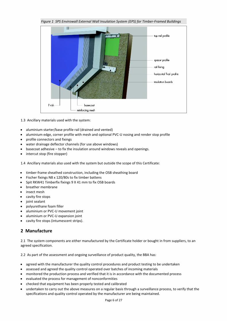
1 Description 1.1 The SPS Envirowall External Wall Insulation System (EPS) for Timber-Framed Buildings (see Figure 1) comprises insulation fixed to horizontal rail support profiles, with reinforced renders. Starter track/base profile rails are fixed at 300 mm centres to the external surface of 11 mm (minimum) Oriented Strand Board (OSB)(1) on timber-framed structures, using spacers to create a minimum 15 mm drained and slightly ventilated cavity. The insulation boards are covered with a reinforced basecoat containing a glass fibre reinforcement mesh. After the basecoat has cured, the surface is primed, before the render finish is applied to the required thickness. (1) See section 4.6, table 2.
1.2 The system components are detailed below: Starter track/base profile
• starter track/base profile — 50 mm x 2.5 mm aluminium base rail profiles with drainage holes
• starter track/base profile fixings(1) — 6.3 diameter x 51 mm length Spit fixing screws positioned at 300 mm centres.
Rail support system
• horizontal rail profiles — PVC holding/supporting rails, fastened to the substrate through the shims and sheathing board at 300 mm centres in a horizontal direction and 500 mm centres in a vertical direction
• vertical splines — PVC T-sections fitted into grooves in the insulation boards to support edges
• spacer profiles — PVC spacers, in a range of thicknesses to maintain the minimum design drainage cavity width of 15 mm
• horizontal support rail profile fixings(1) — 6.3 diameter x 51 mm length Spit fixing screws positioned at 300 mm centres. (1) Other fixings may be used provided they can be demonstrated to have equal or higher pull-out, plate diameter and plate stiffness characteristics.
Insulation(1)
• EPS 70 (white and grey) insulation boards — expanded polystyrene (EPS) grooved-edge boards, 500 by 500 mm, in a range of thicknesses between 50(2) and 200 mm in 10 mm increments, with a nominal density of 15 to 20 kg·m–3, a minimum compressive strength of 70 kN·m-2 and nominal tensile strength of ≥100 kN·m-2. The boards are manufactured to comply with the requirements for EPS 70, Class E material to BS EN 13163 : 2012
• mineral wool firebreak insulation slabs — mineral wool lamella with grooved-edge slabs, 500 by 200 mm in a range of thicknesses between 50(2) and 200 mm in 10 mm increments, with a nominal density of 100 kg·m–3, a minimum compressive strength of 40 kN·m-2 and nominal tensile strength of ≥80 kN·m-2. The slabs are manufactured to comply with the requirements for a mineral wool material to BS EN 13162 : 2012.
(1) For declared thermal conductivity values (λD), see Table 3. (2) Insulation thicknesses of 20, 30, and 40 are available which, along with 50 mm thickness, would generally be used in reveals.

Page 5 of 27
Basecoat
• EnviroRend Basecoat — a factory-batched, polymer-modified, basecoat, supplied as a powder to which 4 to 5 litres of clean water is added. Applied at a coverage of 4.5 to 6 kg·m2 to give a finished a thickness of 4 mm to 6 mm when dry
• RetroBase Basecoat — a factory-batched, polymer-modified basecoat, supplied as a powder to which 4 to 5 litres of clean water is added. Applied at a coverage of 1.6 kg·m2 to give a finished thickness of 5 mm to 7 mm.
Reinforcement mesh
• EnviroMesh Reinforcing Mesh — a multi-stranded, alkali-resistant glassfibre with a polymer coating. Supplied in rolls 1 m wide (4 mm by 4 mm grid size) with a nominal weight of 165 g·m–2
• RetroMesh Reinforcing Mesh — a multi-stranded, alkali-resistant glassfibre with a polymer coating. Supplied in rolls 1 m wide (4 mm by 4 mm grid size) with a nominal weight of 165 g·m–2.
Render finishes EnviroDash Render
• EnviroDash Dash Receiver — a polymer-modified cement-based dash aggregate render, to which 4 to 5 litres of clean water is added, applied at a coverage of 1.5 kg·m2 to give a finished thickness of 6 mm to 10 mm
• SparDash Dash Aggregates — aggregates with a particle size of 3 mm to 6 mm, applied at a coverage of 2 kg/m2. EnviroBrick Render
• EnviroBrick Render Base— a cement-based through-coloured ready to mix mortar layer to which 4 to 5 litres of clean water is added per 25 kg bag. Applied to a thickness of 8 mm to 10 mm with a coverage of 1.8 kg·m2 per mm of thickness (when this starts to stiffen, EnviroBrick Render Face is applied)
• EnviroBrick Render Face — a polymer-modified, cement-based through-coloured face mortar layer to which 4 to 5 litres of clean water is added. Applied to a thickness of 3 mm to 5 mm, with a coverage of 1.8 kg·m2 per mm of thickness (The simulated mortar courses are made by cutting through the top coat of the render).
Silicon Render KR
• Silicon Render KR — a silicone-resin-based, textured coating with particle size of 1.5 mm to 3 mm, applied at a coverage of 1.7 kg/m2 per mm of thickness to give a finished thickness regulated by particle size. Available in a range of colours.
Brickslips
• Acrylic BrickSlip adhesive — water-based, ready to use adhesive and joint mortar. Supplied pre-coloured in white, light grey and brown, and applied to 4 mm thickness. For the application of the Acrylic Speedy Slips
• Acrylic Speedy Slips — polymer-modified pre-coloured acrylic brick slips, available in a rectangular or pistol shape, in range of sizes, 4 mm to 6 mm thick, 65 mm wide by 215 mm long, with 1.4 kg·m3 density or factory-attached to 1m2 mesh.
Page 6 of 27
Figure 1 SPS Envirowall External Wall Insulation System (EPS) for Timber-Framed Buildings
1.3 Ancillary materials used with the system:
• aluminium starter/base profile rail (drained and vented)
• aluminium edge, corner profile with mesh and optional PVC-U nosing and render stop profile
• profile connectors and fixings
• water drainage deflector channels (for use above windows)
• basecoat adhesive – to fix the insulation around windows reveals and openings.
• intercut stop (fire stopper) 1.4 Ancillary materials also used with the system but outside the scope of this Certificate:
• timber-frame sheathed construction, including the OSB sheathing board
• Fischer fixings N8 x 120/80s to fix timber battens
• Spit RKW41 Timberfix fixings 9 X 41 mm to fix OSB boards
• breather membrane
• insect mesh
• cavity fire stops
• joint sealant
• polyurethane foam filler
• aluminium or PVC-U movement joint
• aluminium or PVC-U expansion joint
• cavity fire stops (intumescent strips).
2 Manufacture 2.1 The system components are either manufactured by the Certificate holder or bought in from suppliers, to an agreed specification. 2.2 As part of the assessment and ongoing surveillance of product quality, the BBA has:
• agreed with the manufacturer the quality control procedures and product testing to be undertaken
• assessed and agreed the quality control operated over batches of incoming materials
• monitored the production process and verified that it is in accordance with the documented process
• evaluated the process for management of nonconformities
• checked that equipment has been properly tested and calibrated
• undertaken to carry out the above measures on a regular basis through a surveillance process, to verify that the specifications and quality control operated by the manufacturer are being maintained.

Page 7 of 27
2.3 The management system of SPS Envirowall Ltd has been assessed and registered as meeting the requirements of BS EN ISO 9001 : 2015 by CQS Ltd (Certificate SP240367).
3 Delivery and site handling 3.1 The system components are delivered to site in the packaging and quantities listed in Table 1. Each package carries the product identification, manufacturer’s batch number and the BBA logo incorporating the number of this Certificate.
Table 1 Component supply details
Component Quantity/packaging
Insulation boards Wrapped in plastic film
Starter tracker/base profiles lengths of 2500 mm
PVC horizontal rail profiles lengths of 2500 mm
Vertical splines lengths of 494 mm
EnviroRend Basecoat/RetroBase Basecoat/ EnviroDash Dash Receiver/EnviroBrick Render
25 kg bag
Silicon Render KR 25 kg tub
Spacers EJOT 15 mm 100
Mechanical fixings 6.3 x 51 mm 200
EnviroMesh and RetroMesh 50 m roll, 1 m wide
SparDash Dash Aggregates 20 – 25 kg bag
Acrylic Speedy Slips 100 per box
Acrylic brick slip adhesive 20 kg bucket
3.2 The insulation must be stored on a firm, clean, level base, off the ground and under cover until required for use. Care must be taken when handling to avoid damage. 3.3 The insulation must be protected from prolonged exposure to sunlight, either by storing opened packs under cover or re-covering with opaque polythene sheeting. Care must be taken to avoid contact with solvents or materials containing volatile organic components. The boards must not be exposed to open flame or other ignition sources. Boards that become damaged, soiled or wet should be discarded. 3.4 The basecoat and topcoats must be stored in dry conditions between 5 and 30°C, off the ground and protected from moisture. Contaminated material must be discarded. 3.5 The finishes should be stored in a safe area, under cover, and protected from excessive heat and frost at all times. 3.6 The rails must be protected from humidity and stored indoors.
Assessment and Technical Investigations The following is a summary of the assessment and technical investigations carried out on the SPS Envirowall External Wall Insulation System (EPS) for Timber-Framed Buildings
Design Considerations
4 General 4.1 The SPS Envirowall External Wall Insulation System (EPS) for Timber-\Framed Buildings, when installed in accordance with the Certificate holder’s instructions and this Certificate, is satisfactory for use in reducing the thermal transmittance (U-value) of external timber framed walls of new and existing buildings. It is essential that the detailing techniques specified in this Certificate are carried out to a high standard if the ingress of water into the insulation is to be avoided and the full thermal benefit obtained from treatment with the system (eg the insulation must be protected by an overhang, and window sills should be designed and installed so as to direct water away from the building).

Page 8 of 27
4.2 For improved thermal/carbon-emissions performance, the designer should consider additional/alternative fabric and/or services measures. 4.3 The system is for application to the outside of external timber framed substrates, on new or existing domestic and non-domestic buildings up to 18 m in height. Prior to installation of the system, substrate/ wall surfaces should comply with section 14 of this Certificate.
4.4 New walls subject to national Building Regulations should be constructed in accordance with the
relevant recommendations of
• BS EN 1995-1-1 : 2004 and BS EN 1995-1-2 :2004 and their UK National Annex
• BS 8000-0 : 2014
• BS EN 338 : 2016 and BS EN 14081-1 : 2016.
• BS EN 300 : 2006
4.5 The system must provide a minimum 15 mm wide partially ventilated and drained cavity(1)(2) between the sheathing board and the insulation panels. This cavity is slightly ventilated to the outside air and will, therefore, affect the thermal performance of the insulation system. Openings should be between 500 mm2 and 1500 mm2 per metre of length (in the horizontal direction). The openings must be kept clean, free of obstructions and capable of draining freely. More information is available in BS EN ISO 6946 : 2007. (1) Horizontal deflection channels which obstruct the cavity should not be used to support the insulating render system. (2) Cavities must not contain electrical cables other than meter tails.
4.6 The structural frame of the building, including the sheathing boards, is the responsibility of the building designer and is outside the scope of this Certificate. However, the structural frame (and sheathing-associated fixings) should be structurally adequate, and must be designed to resist cracking due to wind and other forces, be able to withstand the loads applied from the insulation system (see Table 2 for minimum specifications for system installations) and give an acceptable resistance to pull-out of fixings (see Table 6). It is essential that appropriate movement joints are incorporated into the system.
Table 2 Minimum timber framed construction specification
Item Specifications
Timber-framed structure(1) Exterior grade in accordance with BS EN 338 and BS EN 14081-1 and dry graded and marked in accordance with BS 4978.
The timber structure should be no less than 37 mm thick with a minimum width of 72 mm or 0.026 times the panel height in mm, whichever is the greater
Sheathing board(1)
(OSB) 11 mm thick minimum, with a minimum density of 600 kg·m–3 and modulus of elasticity in bending > 3500 (N·m–2), 18 N.mm-2 bending strength – major axis
Manufactured to BS EN 300 : 2006 Class 3
(1) The board and the structural timber frame must be of an exterior grade and to the minimum acceptable specification given here. However, both components are outside the scope of this Certificate.
4.7 New walls not subject to regulatory requirements should also be built in accordance with the Standards identified in section 4.4 of this Certificate. 4.8 Movement joints should be incorporated into the system in line with existing expansion joints in accordance with the Certificate holder’s recommendations for the specific installation. 4.9 The designer should select a construction appropriate to the local wind-driven rain index, paying due regard to the design detailing, workmanship and materials to be used. 4.10 The system will improve the weather resistance of a wall and provide a decorative finish. However, care should be taken to ensure that walls are adequately weathertight prior to application. The system should only be installed where there are no signs of dampness on the inner surface of the wall.
Page 9 of 27
4.11 The effect of the system on the acoustic performance of a construction is outside the scope of this Certificate. 4.12 The fixing of sanitary pipework, plumbing, rainwater goods, satellite dishes, clothes lines, hanging baskets and similar items to the system is outside the scope of this Certificate. See section 4.13 of this Certificate. 4.13 External pipework and ducts should be removed before installation and alterations made to underground drainage, to accommodate repositioning of the pipework to the finished face of the system. The Certificate holder can advise on suitable fixing methods, but these are outside the scope of this Certificate. 4.14 It is essential that this system is installed and maintained in accordance with the conditions set out in this Certificate.
5 Practicability of installation The system should only be installed by specialised contractors who have successfully undergone training and registration by the Certificate holder (see section 15). Note: The BBA operates a UKAS-accredited Approved Installer Scheme for external wall insulation (non mandatory); details of approved installer companies are included on the BBA’s website (www.bbacerts.co.uk).
6 Thermal performance 6.1 Calculations of thermal transmittance (U-value) should be carried out in accordance with BS EN ISO 6946 : 2007 and BRE Report BR 443 : 2006, using the insulation manufacturer’s declared thermal conductivity (λD value) of the insulation given in Table 3 of this Certificate.
Table 3 Thermal conductivity of the insulation (λD value)
Insulation type Thickness(1) (mm)
Thermal conductivity (W·m–1·K–1)
white EPS 50 to 200 0.038
grey EPS 60 to 200 0.032 (1) Insulation thicknesses of 20, 30 and 40 mm are available, which would generally be used in reveals, along with
50 mm thickness.
6.2 The U value of a completed wall will depend on the selected insulation type and thickness, profile/spline material, and the internal finish. Calculated U values for sample constructions in accordance with the national Building Regulations are given in Table 4 and are based on the thermal conductivities given in Table 3. In order to take account of the correction in a combined method U-value calculation, Table 5 may be used.

Page 10 of 27
Table 4 Insulation thickness required to achieve design U values given in the national Building Regulations(1)(2)(3)(4)(5)
U-value
(W·m–2·K–1) Insulation thickness requirement
(mm)
PVC rails
EPS 70 white EPS 70 grey
0.18 — —
0.19 — 200
0.25 170 150
0.26 160 140
0.28 150 130
0.30 130 110
0.35 110 100 (1) Wall construction inclusive of 12.5 mm plasterboard (λ = 0.25 W·m–1·K–1), 11 mm OSB (λ = 0.13 W·m–1·K–1), 89 mm
timber frame (15%) bridged with air cavity, and 6.5 mm external render (λ = 1.0 W·m–1·K–1). (2) Assumes an air gap correction (ΔU) of 0.01 and incremental insulation thicknesses of 10 mm. (3) A U value correction should be included for the PVC rails and splines as described in Table 5. (4) When applying the maximum available insulation thickness, these walls can achieve U value from 0.19 to
0.35 W·m–2·K–1 depending on the wall type. (5) Cavity assumed to be partly ventilated, having a ventilation rate of 728.6 mm2·m.
Table 5 Corrections to U values for PVC profiles and splines using a combined method
Insulation thickness
(mm)
PVC profile linear thermal transmittance (ψ)
PVC spline linear thermal transmittance (ψ)
Δψ W∙m-1∙K-1
40 0.007 0.003
50 0.005 0.002
60 0.004 0.002
70 0.003 0.001
80 0.022 0.001
90 0.002 0.001
100 0.002 0.001
110 0.001 0.001
120 0.001 0.001
130 0.001 0.000
140 0.001 0.000
150 0.001 0.000
160 0.001 0.000
170 0.001 0.000
180 0.001 0.000
190 0.000 0.000
200 0.001 0.000
Correction to U-value should be made as follows: U = U0 + [L* ψ]/A Where: U0 is U-value of wall without rails/splines present Ψ is linear thermal transmittance of rail L is length of rail which may be assumed to be 2m for both profile and spline A is wall area which may be assumed to be 1m2 for both profile and spline

Page 11 of 27
6.3 Care must be taken in the overall design and construction of junctions with other elements and openings to minimise thermal bridges and air infiltration. Detailed guidance can be found in the documents supporting the national Building Regulations.
7 Strength and stability
General
7.1 The Certificate holder is ultimately responsible for the design of installations incorporating the system and must verify that a suitably experienced and qualified individual (with adequate professional indemnity) establishes that:
• the wind loads on the different zones of the building’s elevation for the specific geographical location have
been calculated correctly (see section 7.2)
• the system can adequately resist and safely transfer the calculated loads for all possible failure modes (see sections 7.2 to 7.5)
• the substrate wall has adequate strength to resist the additional loads that may be applied as a result of installing the system (ignoring any positive contribution that may occur from the system), and gives an acceptable resistance to pull-out of fixings.
7.2 The wind loads on the walls should be calculated, taking into account all relevant factors such as location and topography, in accordance with BS EN 1991-1-4 : 2005 and its UK National Annex. All the factors affecting wind load on each elevation and specific zone of the building must be considered. In accordance with BS EN 1990 : 2002, a partial factor of 1.5 must be applied to the characteristic values determined from BS EN 1991-1-4 to establish the ultimate wind load to be resisted by the system. 7.3 Installations correctly designed in accordance with this Certificate will safely accommodate the applied loads due to self-weight and wind.
7.4 Positive wind load is transferred to the substrate wall directly via bearing and compression of the render and insulation through the sheathed timber frame structure with the rail and rail profile fixings. 7.5 Negative wind pressure (suction) is transferred to the substrate wall via(1):
• the combination of the bond of insulation and render (resistance is >80 kN·m-2), the strength between sheathed
timber frame substrate, and the rail and rail profile fixing to the structure.
• the pull-out resistance of the rail fixing from the sheathed timber frame substrate wall (see 7.6)
• the strength of the rail profiles. (1) Further guidance is available from BBA Guidance Note 1, available on the BBA website (www.bbacerts.co.uk).
7.6 Typical characteristic pull-out resistances for the fixings from specific sheathing board are given in Table 6; the values are dependent on the fixing type and must be selected to suit the specific loads and substrate concerned. However, in situations where suitable data does not exist(1), the characteristic pull-out resistance must be established from site-specific pull-out tests, conducted on the substrate of the building to determine the minimum resistance to pull-out failure of the fixings. The characteristic pull-out resistance should be determined in accordance with the guidance given in EOTA TR051 (minimum test characteristic value = 0.6 x mean of 5 lowest test results). This characteristic pull-out resistance should then be divided by the partial factor given in Table 6 to obtain the design pull-out resistance of the fixings. (1) To qualify as suitable data the age and condition of the substrate must be equivalent to that used to establish the values given in Table 6.

Page 12 of 27
Table 6 Profile fixing typical characteristic pull-outs strengths
Fixing type Substrate facing Characteristic pull-out strength(1)
(kN)
Spit 6.3 x 51 mm with 10 mm head diameter
Through the support rails, cavity spacer, 11 mm OSB
0.5(2)
(1) A safety factor of 1.5 should be applied to obtain the design pull-out values. (2) Figure obtained from fixing’s datasheet.
7.7 The number of fixings through the rails and the profile span and centres were determined by test. Provided the substrate wall is suitable and an appropriate fixing is selected, the profiles will adequately support and transfer the weight of the systems and wind loads to the substrate wall at the maximum spacing given in this Certificate (see section 7.8). 7.8 Tests were carried out on a timber-framed substrate with the system installed with PVC horizontal T rail profiles attached to 11 mm thick OSB board (providing a minimum 15 mm cavity) spaced at 500 mm centres and mechanically fixed with screws at 300 mm horizontal centres. The insulation boards slotted into the T rail profiles and vertically connected board edges with T splines indicated that the systems can resist a design wind load pressure(1) of 0.95 kN·m -2: see Figure 3 and sections 4.6 and 7.10. (1) The design resistance is determined by dividing the characteristic resistance value obtained from a dynamic wind uplift test by a partial safety
factor of 2.5.
7.9 The permitted deflection of the supporting structure incorporating sheathed timber frame constructions should be designed in accordance with BS EN 1995-1-1 : 2004, ie span L/360 mm. Deflection must be limited to prevent damage to the systems — the Certificate holder’s advice should be sought. The steel frame spacings must not exceed 600 mm.
7.10 It is very important that the data assessed in sections 7.6 and 7.8 is analysed as follows to ensure the safe design, and the minimum value is used to determine the critical failure path: Rd ≥ We
Rdpull-out = n * NRd1
Rddynamic wind uplift = NRk/γm
Where: Rd is the design ultimate resistance taken as the minimum of Rdpull-out and Rddynamic wind uplift We is the applied ultimate wind pressure per m2 n is the number of fixing per m2, which must be based on the fixing span described in section 7.8 of this Certificate. NRd1 is the design pull out resistance per fixing per m2 NRk is the characteristic resistance obtained from the wind uplift test γm is the partial safety factor (determined by the mode of failure). Impact resistance 7.11 Hard body impact tests were carried out in accordance with ETAG 004 : 2013. The system is suitable for use in the Categories(1) up to and including those specified in Table 7 of this Certificate.

Page 13 of 27
Table 7 Impact resistance
Render systems: Basecoat + finishing coats indicated below:
Category(1)
Single mesh
EnviroRend/RetroBase Basecoat + EnviroDash Dash Receiver + spar aggregates Category II
EnviroRend/RetroBase Basecoat + Silicon KR
EnviroRend/RetroBase Basecoat + EnviroBrick render (mortar coloured + EnviroBrick effect) Category I
EnviroRend/RetroBase Basecoat + acrylic brickslips (Speedy Slips) and Speedy Slip adhesive
(1) The use Categories are defined in ETAG 004 : 2013 as: ● Category I — a zone readily accessible at ground level to the public and vulnerable to hard body impacts but not subjected to
abnormally rough use ● Category II — a zone liable to impacts from thrown or kicked objects, but in public locations where the height of the system will limit
the size of the impact; or at lower levels where access to the building is primarily to those with some incentive to exercise care ● Category III — a zone not likely to be damaged by normal impacts caused by people or by thrown or kicked objects.
8 Behaviour in relation to fire
8.1 The reaction to fire classification for the system in accordance with BS EN 13501-1 : 2007 is given in Table 8.
Table 8 System fire classification
System Standards Fire classification
Rendering system Basecoats (EnviroRend or RetroBase) + finishing coats indicated below
BS EN 13501-1 : 2007 B-s1, d0 Silicon KR render finish EnviroBrick render EnviroDash Dash Receiver+ spar aggregates Acrylic brick slips (Speedy Slips) and slip adhesive
8.2 The fire classification applies to the full range of thicknesses covered by this Certificate (see section 1.2). 8.3 The insulation is not classified as non-combustible or of limited combustibility, and the system is restricted for use in buildings up to 18 m in height. 8.4 For houses in Scotland, and for all buildings in England and Wales and Northern Ireland, the system is considered suitable for use on, or at any distance from, the boundary.
8.5 For flats and maisonettes and non-domestic buildings in Scotland, the system is suitable only for use more than one metre from the boundary.
8.6 The system is not classified as non-combustible; therefore, calculations for unprotected areas may apply depending on the fire resistance characteristics of the wall.
8.7 For application to second storey walls and above, it is recommended that the designer considers at least one stainless steel fixing per square metre and cavity and fire barriers in line with compartment walls and floors as advised in BRE Report BR 135 : 2013 (see Figure 2 of this Certificate).

Page 14 of 27
Figure 2 Fire barrier detail
9 Proximity of flues and appliances Where the system is installed in close proximity to certain flue pipes, the relevant provisions of the national Building Regulations should be met: England and Wales — Approved Document J Scotland — Mandatory Standard 3.19, clause 3.19.4(1)(2)
(1) Technical Handbook (Domestic). (2) Technical Handbook (Non-Domestic).
Northern Ireland — Technical Booklet L.
10 Water resistance
10.1 The system will provide a degree of protection against rain ingress. However, care should be taken to ensure that walls are adequately watertight prior to application of the system. The system must only be installed where there are no signs of dampness on the inner surface of the substrate other than those caused solely by condensation.
10.2 Designers and installers should take particular care in detailing around openings, penetrations and movement joints to minimise the risk of rain ingress.

Page 15 of 27
10.3 The guidance given in BRE Report BR 262 : 2002 should be followed in connection with the watertightness of solid wall constructions. The designer should select a construction appropriate to the local wind-driven index, paying due regard to the design detailing, workmanship and materials to be used. 10.4 At the top of walls, the system should be protected by a coping, overhang or other detail designed for use with this types of system (see section 16). On flat roof parapet walls, waterproofing and drainage must be adequate and in good conditions.
11 Risk of condensation
11.1 Designers must ensure that an appropriate condensation risk analysis has been carried out for all parts of the construction, including openings and penetrations at junctions between the insulation system and windows, to minimise the risk of condensation. The recommendations of BS 5250 : 2011 should be followed.
Surface condensation
11.2 Walls will limit the risk of surface condensation adequately when the thermal transmittance
(U value) does not exceed 0.7 W·m–2·K–1 at any point and the junctions with other elements and openings comply with section 6.3 of this Certificate.
11.3 Walls will adequately limit the risk of surface condensation when the thermal transmittance (U value) does not exceed 1.2 W·m–2·K–1 at any point. Guidance may be obtained from BS 5250 : 2011, Section 4, and BRE Report BR 262 : 2002.
Interstitial condensation
11.4 Walls incorporating the system will adequately limit the risk of interstitial condensation when they
are designed and constructed in accordance with BS 5250 : 2011 (Section 4 and Annexes D and G) and section 11.5 of this Certificate.
11.5 The water vapour resistance factor (μ) for the insulation and the equivalent air layer thickness (sd) of the reinforced basecoat with finish coat may be taken from Table 9.
Table 9 Water vapour resistance factor and equivalent air layer thickness
Material Thickness (mm)
Sd (m) µ
White EPS 70 40 to 200 - 20 to 40(1)
Grey EPS 70 60 to 200 - 20 to 40(1)
EnviroRend/RetroBase basecoat + Silicon KR 6.5 0.16(2) -
EnviroRend/RetroBase basecoat + dash receiver (EnviroDash)
11 0.13(2) -
EnviroRend/RetroBase basecoat + acrylic brick slip (Speedy Slips) and adhesive
12 1.15(2) -
EnviroRend/RetroBase basecoat + EnviroBrick top coat + EnviroBrick effect render finish
5 0.08 -
(1) The insulation values were obtained from BS EN ISO 10456 : 2007, Table 4. It is recommended that the lower figure is used when assessing the interstitial condensation risk analysis. (2) These values were obtained with 2 mm grain particle size.

Page 16 of 27
12 Maintenance and repair
12.1 An initial inspection should be made within 12 months and regularly thereafter to include:
• visual inspection of the render for signs of damage. Cracks in the render exceeding 0.2 mm must be repaired
• examination of the sealant around openings and service entry points
• visual inspection of architectural details designed to shed water to confirm that they are performing properly
• visual inspection to ensure that water is not leaking from external downpipes or gutters; such leakage could penetrate the rendering
• necessary repairs effected immediately and the sealant joints at window and door frames replaced at regular intervals
• maintenance schedules, which should include the replacement and resealing of joints, for example between the insulation system and window and door frame.
12.2 Damaged areas must be repaired using the appropriate components and procedures detailed in the Certificate holder’s installation instructions and in accordance with BS EN 13914-1 : 2005.
13 Durability
13.1 The system will have a service life of not less than 30 years, provided any damage to the surface finish is repaired immediately and regular maintenance is undertaken, as described in section 12.
13.2 Renders containing Portland cement may be subject to lime bloom. The occurrence of this may be reduced by avoiding application in adverse weather conditions. The effect is transient and is less noticeable with lighter colours. 13.3 The renders may become discoloured with time, the rate depending on the initial colour, the degree of exposure and atmospheric pollution, as well as the design and detailing of the wall. In common with traditional renders, discoloration by algae and lichens may occur in wet areas. The appearance may be restored by a suitable power wash or, if required, by overcoating. 13.4 To maintain a high quality aesthetic appearance, it may be necessary to periodically overcoat the building using system-compatible coatings as described in section 1.2, and as recommended by the Certificate holder, and in accordance with BS EN 1062-1 : 2004. Care should be taken not to adversely affect the water vapour transmission or fire characteristics of the system. The advice of the Certificate holder should be sought as to the suitability of a particular product.
Installation
14 Site survey and preliminary work 14.1 A pre-installation survey of the property must be carried out to determine suitability for treatment and any repairs necessary to the building structure before application of the system. A specification must be prepared for each elevation of the building indicating:
• the position of beads
• detailing around windows, doors and at eaves
• damp-proof course (dpc) level
• the exact position of expansion joints, if required
• areas where flexible sealants must be used
• any alterations to external plumbing
• the position of fire and cavity stop barriers. 14.2 The survey should include tests conducted on the walls of the building by the Certificate holder or their approved installers (see section 15) to determine the pull-out resistance of the specified mechanical fixings for the substrate to withstand the building’s expected wind loading, based on calculations using the fixing’s pull-off resistance test data. In

Page 17 of 27
addition, the type and minimum number of fixings are selected (see section 7). The advice of the Certificate holder should be sought to ensure the proposed fixing pattern is sufficient. 14.3 Before the system is applied, the timber should be dry (as near as is practicable to the moisture content appropriate to its climatic condition in the completed structure). Higher moisture contents may be accepted during erection provided that it is ensured that the timber can dry to the desired moisture content after installation. 14.4 The flatness of surfaces must be checked; this may be achieved using a straight edge spanning the storey height. Any irregularities must be made good prior to installation to ensure that the insulation boards and rail support profiles are installed with a smooth, in-plane finished surface. 14.5 On existing buildings, purpose-made window sills must be fitted to extend beyond the finished face of the system. New buildings should incorporate suitably deep sills. 14.6 For new buildings, internal wet work (eg screed or plastering) should be completed and allowed to dry prior to the installation of the system. 14.7 All modifications and necessary repairs to the building structure must be completed before installation commences.
15 Approved installers Application of the system, within the context of this Certificate, must be carried out by approved installers recommended or recognised by the Certificate holder. Such an installer is a company:
• employing operatives who have been trained and approved by the Certificate holder to install the system
• which has undertaken to comply with the Certificate holder’s application procedure, containing the requirement for each application team to include at least one member operative trained by the Certificate holder
• subject to at least one inspection per annum by the Certificate holder to ensure suitable site practices are being employed. This may include unannounced site inspections.
16 Procedure General 16.1 The application must be carried out in accordance with the Certificate holder’s current installation instructions. 16.2 Weather conditions should be monitored to ensure correct application and curing conditions. Application of coating materials must not be carried out at temperatures below 5°C or above 30°C, or if exposure to frost is likely, and the coating must be protected from rapid drying. In addition, cementitious-based renders must not be applied if the temperature will fall below 0°C within 72 hours of completion. 16.3 All rendering should be in accordance with the relevant recommendations of BS EN 13914-1 : 2005. Positioning and securing insulation boards 16.4 The starter/base profile is secured to the sheathing board above the dpc (see Figure 3) using 6.3 diameter x 51 mm length Spit fixings screws at approximately 300 mm centres. Starter/base profile connectors are inserted at the base of the system’s joints. Extension profiles are fixed to the front lip of the starter/base profile. Stop end profiles are installed where required. A plastic clip of mesh bead is clipped over the edge of the bead.

Page 18 of 27
Figure 3 Typical section of starter/base
16.5 Packing shims are used at fixing points behind the starter/base profile where it is necessary to overcome surface
irregularities and to maintain alignment of the face of the insulation.
16.6 The horizontal rail profiles and 15 mm spacers are mechanically fixed to the sheathing board and through the
timber-frame substrate with hammer-drive screws, at a maximum of 300 mm centres either side of the rail. Rails may
need packing to ensure they are true to line and level. Drainage deflection channels are mechanically fixed over all
window and door openings, and horizontal and vertical intumescent strips are installed following the designer’s
instructions. Care should be taken not to overdrive the fixings.

Page 19 of 27
Figure 4 Rail profile fixing pattern
16.7 The first insulation board is positioned onto the base profile and is used to position the first horizontal rail. The fixing rail slots into the pre-cut groove in the insulation board. The level is checked and the rail is positioned away from the substrate using a 15 mm spacer. It is important that the fixing rail fits tightly and locates fully into the groove in the insulation; it should not be forced into position. 16.8 Once the horizontal fixing rails are in position and the insulation board is placed onto the fixing rail, the vertical splines are positioned and fixed between the horizontal rails and insulation grooves. The next insulation board is slotted into place. It is important to ensure that the fixing rails fit securely into the grooved insulation and that the insulation boards are tightly butted together, particularly at corners. 16.9 Joints greater than 2 mm between boards should be filled with slivers of insulation board or PU foam. Gaps greater than 10 mm should be closed by repositioning or, where appropriate, by cutting boards to fit. Alignment should be checked as work proceeds. 16.10 Subsequent boards are positioned so that the joints are staggered by a minimum of 100 mm and any open joints in the insulation system filled and overlapped at the building corners (see Figure 5). Installation continues until the whole wall is completely covered including, where appropriate, the building soffits.

Page 20 of 27
Figure 5 Typical arrangement of insulation boards at corners
16.11 Care must be taken to ensure alignment is checked as work proceeds. The surface of the boards should be smooth without high spots or irregularities. Fire barriers must be installed where required following the designer’s instructions. 16.12 To fit around details such as doors and windows, insulation boards may be cut with a sharp knife or a fine-tooth saw. Purpose-made window-sills, seals and deflection channels are fitted; these are designed to prevent or manage water ingress and allow water to be shed clear of items bridging the cavity. Corner profiles are fixed to all building corners and to door and window heads and jambs. 16.13 All corners are fixed with mesh angles installed with adhesive mortar. Where appropriate, application-specific profiles are installed, to allow rainwater to drain away. Movement joints 16.14 Generally, movement joints are not required in the system but, if an expansion joint is already incorporated in the substrate, a movement joint must be provided through the system, using an expansion joint profile (see Figure 6). 16.15 Where required, render surface-mounted vertical movement joints should extend through render system.

Page 21 of 27
Figure 6 Vertical movement joint detail
16.16 Expansion beads are fixed vertically in predetermined positions where necessary, according to the installation
specification and the individual requirements of each job.
Application of basecoat and reinforcement mesh
16.17 Prior to the application of the basecoat, the pre-compressed sealing tape used on at window and door frames,
overhanging eaves, gas and electric meter boxes, and wall vents. Alternatively, gun-applied joint sealants or proprietary
sealing beads can be used in accordance with the Certificate holder’s instructions.
16.18 The basecoat is prepared by mixing the contents of each 25 kg bag with approximately 4 to 5 litres of cold, clean
water, using a paddle mixer. Mixing time should be at least five minutes after the addition of the last bag of render to
allow an even dispersion of resins. It is applied over the insulation boards using a stainless steel trowel and floated with
a Darby float to an approximate 4 mm thickness. Reinforcement mesh is applied (with its concave surface to the wall)
and is immediately embedded into the basecoat by trowelling from the centre to the edge and an additional light coat
of basecoat is applied (whilst the first coat is still wet) to ensure the mesh is free of wrinkles and completely covered
and that the required minimum thickness of basecoat is achieved. The mesh must be placed in the top one third of the
basecoat.
16.19 The first layer of basecoat should be left to harden.
16.20 Additional pieces of reinforcing mesh (500 mm by 300 mm) are used diagonally at the corners of openings, as
shown in Figure 7.

Page 22 of 27
Figure 7 Additional reinforcement at openings
16.21 PVC meshed corner beads are bedded into the basecoat at external corners and around openings as required. 16.22 The second layer of basecoat is applied to a thickness of between 3 mm and 4 mm to achieve an overall minimum thickness of 6 mm when dry, ensuring all mesh is covered before the application of the finish render. The drying time will depend upon weather conditions, but will typically be at least 12 hours. Decorative finishes EnviroDash Dash Receiver 16.23 The EnviroDash Receiver is mixed until the correct workability is achieved, and trowelled onto the basecoat to a thickness of between 6 mm and 10 mm according to the thickness of the spar dash aggregates. While the EnviroDash Receiver is still soft, SparDash washed aggregate is thrown or sprayed on, ensuring a uniform covering. Where necessary, the aggregate can be lightly tampered with a wooden float to ensure a good bond is achieved. See also section 1.2 of this Certificate. EnviroBrick 16.24 The render is applied in two different coloured coats and in two stages. The grey mortar-coloured EnviroBrick Render Base is trowelled onto the basecoat to a thickness of 8 mm to 10 mm and, when starting to stiffen, the EnviroBrick Render Face brick-coloured coat is applied to a thickness of 3 mm to 5 mm. To simulate a brick texture, the second coat can be lightly brushed. The simulated mortar courses are made by cutting through the face coat to expose the lower coat. Spirit levels and straight edges should be used to ensure accuracy when cutting into the surface. Any loose material can be removed with a stiff brush once the cutting process is complete. See also section 1.2 of this Certificate. Silicon KR 16.25 The render is applied to a thickness of 1.5 mm to 3 mm. A straight edge can be used to help ensure a flat surface, and wet sponges, wooden mortar boards or similar tools can be used to create the desired finish.
Acrylic brick slip and adhesive 16.26 The brick slip adhesive should be thoroughly stirred within its tub; a small amount of water can be added to adjust the consistency. No more adhesive than can be immediately covered by the brick slips should be applied. The adhesive is applied to the surface of the wall using a 5 mm notched trowel and combed horizontally in order to achieve an overall thickness between 5 mm and 7 mm, including the slips. The brick slips should be applied from the top down,

Page 23 of 27
starting in the corner. The brick slip can then be floated into position and pressed into the mortar by applying gentle pressure. Any air trapped behind the slips should be removed. The slips can be cut using a sharp Stanley knife. The pointing process should begin immediately after the slips have been installed. The wet mortar can be spread evenly along the joints and up the sides of the slips to seal the joints; a hand brush can be used to remove any loose mortar.
General 16.27 Prior to setting, silicone render finishes are textured with a plastic float to give an even texture and to remove all trowel lines. Elevations should be completed in one application and finished to natural breaks in the render, ie beads or building corners. 16.28 The drying time is dependent on ambient conditions, but will typically be 12 hours depending on the installed system thickness. 16.29 Care should be taken in the detailing of the system around such features as openings, projections and at eaves (see Figures 8, 9, 10 and 11) to ensure adequate protection against water ingress and to limit the risk of water penetrating the system. 16.30 On completion of the installation, external fittings, eg rainwater goods, must be securely fixed to timber grounds and extended to the face of the system during installation.
Figure 8 Roof eaves detail

Page 24 of 27
Figure 9 Insulated window head detail
Figure 10 Window sill detail

Page 25 of 27
Figure 11 Insulated window reveal detail
Technical Investigations
17 Investigations 17.1 Tests were conducted and the results assessed to determine:
• reaction to fire performance
• bond strength
• hygrothermal performance and resistance to freeze-thaw
• watertightness – resistance to wind-driven rain under pulsating pressure
• resistance to hard body impact
• water absorption and water vapour permeability of the renders
• wind load resistance
• pull-through strength of fixings
• Soft body impact.
17.2 An assessment was made of data relating to:
• durability
• the risk of interstitial condensation
• thermal conductivity.
17.3 The practicability of installation and the effectiveness of detailing techniques were assessed.
17.4 The manufacturing process was evaluated, including the methods adopted for quality control, and details were
obtained of the quality and composition of materials used.

Page 26 of 27
Bibliography
BS 4978 : 2007 + A1 : 2001 Visual strength grading of softwood — Specification
BS 5250 : 2011 + A1 : 2016 Code of practice for control of condensation in buildings
BS EN 338 : 2016 Structural timber — Strength classes
BS EN 1062-1 : 2004 Paints and varnishes — Coating materials and coating systems for exterior masonry and concrete — Classification
BS EN 1990 : 2002 + A1 : 2016 Eurocode — Basis of structural design
BS EN 1995-1-1 : 2004 + A1 : 2008 Eurocode 5 : Design of timber structures — General — Common rules and rules for buildings NA to BS EN 1995-1-1 : 2004 + A1 : 2008 UK National Annex to Eurocode 5 : Design of timber structures — General — Common rules and rules for buildings
BS EN 13162 : 2012 + A1 : 2015 Thermal insulation products for buildings — Factory made mineral wool (MW) products — Specification
BS EN 13163 : 2012 + A1 : 2015 Thermal insulation products for buildings — Factory made expanded polystyrene (EPS) products — Specification
BS EN 13501-1 : 2007 + A1 : 2009 Fire classification of construction products and building elements — Classification using test data from reaction to fire tests
BS EN 13914-1 : 2005 Design, preparation and application of external rendering and internal plastering — External rendering
BS EN 13986 : 2004 + A1 : 2015 Wood-based panels for use in construction — Characteristics, evaluation of conformity and marking
BS EN 14081-1 : 2016 Timber structures — Strength graded structural timber with rectangular cross section — General requirements
BS EN ISO 6946 : 2007 Building components and building elements — Thermal resistance and thermal transmittance — Calculation method
BS EN ISO 9001 : 2008 Quality management systems — Requirements
BS EN ISO 10456 : 2007 Building materials and products — Hygrothermal properties — Tabulated design values and procedures for determining declared and design thermal values
BS EN ISO 14001 : 2004 Environmental management systems — Requirements with guidance for use
BRE Report 135 (BR 135 : 2013) Fire performance of external thermal insulation for walls of multistorey buildings
BRE Report 262 (BR 262 : 2002) Thermal insulation: avoiding risks
BRE Report 443 (BR 443 : 2006) Conventions for U-value calculations
ETAG 004 : 2013 Guideline for European Technical Approval of External Thermal Insulation Composite Systems (ETICS) with Rendering
ETAG 014 : 2011 Guideline for European Technical Approval of Plastic Anchors for Fixing of External Thermal Insulation Composite Systems with Rendering

Page 27 of 27
Conditions of Certification
18 Conditions 18.1 This Certificate: ● relates only to the product/system that is named and described on the front page ● is issued only to the company, firm, organisation or person named on the front page – no other company, firm,
organisation or person may hold claim that this Certificate has been issued to them ● is valid only within the UK ● has to be read, considered and used as a whole document – it may be misleading and will be incomplete to be
selective ● is copyright of the BBA ● is subject to English Law. 18.2 Publications, documents, specifications, legislation, regulations, standards and the like referenced in this Certificate are those that were current and/or deemed relevant by the BBA at the date of issue or reissue of this Certificate. 18.3 This Certificate will remain valid for an unlimited period provided that the product/system and its manufacture and/or fabrication, including all related and relevant parts and processes thereof: ● are maintained at or above the levels which have been assessed and found to be satisfactory by the BBA ● continue to be checked as and when deemed appropriate by the BBA under arrangements that it will determine ● are reviewed by the BBA as and when it considers appropriate. 18.4 The BBA has used due skill, care and diligence in preparing this Certificate, but no warranty is provided. 18.5 In issuing this Certificate the BBA is not responsible and is excluded from any liability to any company, firm, organisation or person, for any matters arising directly or indirectly from: ● the presence or absence of any patent, intellectual property or similar rights subsisting in the product/system or any
other product/system ● the right of the Certificate holder to manufacture, supply, install, maintain or market the product/system ● actual installations of the product/system, including their nature, design, methods, performance, workmanship and
maintenance ● any works and constructions in which the product/system is installed, including their nature, design, methods,
performance, workmanship and maintenance ● any loss or damage, including personal injury, howsoever caused by the product/system, including its manufacture,
supply, installation, use, maintenance and removal ● any claims by the manufacturer relating to CE marking. 18.6 Any information relating to the manufacture, supply, installation, use, maintenance and removal of this product/system which is contained or referred to in this Certificate is the minimum required to be met when the product/system is manufactured, supplied, installed, used, maintained and removed. It does not purport in any way to restate the requirements of the Health and Safety at Work etc. Act 1974, or of any other statutory, common law or other duty which may exist at the date of issue or reissue of this Certificate; nor is conformity with such information to be taken as satisfying the requirements of the 1974 Act or of any statutory, common law or other duty of care.
British Board of Agrément Bucknalls Lane Watford Herts WD25 9BA
©2017
tel: 01923 665300
[email protected] www.bbacerts.co.uk