agricultural machinery technology 6 agricultural machinery technology takashi kataoka 1. beginning...
TRANSCRIPT

Agricultural Machinery Technology
Takashi Kataoka
Laboratory of Crop Production Engineering
Research Faculty of Agriculture
Hokkaido University
Email:[email protected]

Chapter 6
Agricultural Machinery Technology
Takashi Kataoka
1. Beginning of Mechanization in Agriculture in Hokkaido (1) History of College Farm of Sapporo Agricultural College
Dr. William S. Clark, who was the president of Massachusetts
Agricultural College in the U.S., was invited as vice-president of the Sapporo
Agricultural College. He came with two other professors, Dr. Wheeler and Dr.
Penharrow, in July 1876. The Sapporo Agricultural College was established on
August 4, 1876.
On September 8, 1876, Dr. Clark requested the governor to build a
well-equipped farm system. The ownership of the college farm was transferred
from the governor to the college. The college had two different types of farms.
The first farm was used for students’ training in crop production, and the second
was used as a model for dairy farming in Hokkaido. A new barn (Fig. 6-1) was
got constructed by Dr. Clark as a model for dairy farming in Hokkaido.
Prof. Brooks was invited to the Sapporo Agricultural College in
February, 1877 and Dr. Clark left Sapporo in April, 1877. Prof. Brooks suggested
the construction of a corn barn (Fig. 6-2). He also imported many types of
agricultural implements and tools for crops and cattle in May, 1877. He led
both education and training on modern agriculture in Japan, and a considerable
fruitful knowledge was generated from 1877 to 1879. The clock tower and the
model barn of the Sapporo Agricultural College were built in 1877. Besides corn
barn, other houses were also built and a new dairy farming system was
practiced. Fig. 6-3 shows the tower silo used for making silage.
In 1969, the buildings of the second farm of the Sapporo Agricultural
College were designated as “National Important Cultural Properties”. In 2001,
these were recognized as “Treasures of Hokkaido, and Properties for Future”.
6-1

Fig. 6-1. The Model Barn.
Fig. 6-2. Corn Barn.
Fig. 6-3. Tower Silo.
6-2

Today, these are well known in Japan and considered as important heritages.
(2) The Model Barn
The Sapporo Agricultural College was the first to have the model barn.
The building was originally named “The Delivery Room and the Stable”. However,
Dr. Clark, the first vice-president of the college, named it “The Model Barn”
because he thought this as the symbolic model of the modern agriculture in
Hokkaido. Following Dr. Clark’s suggestion, Professor Wheeler, the second vice-
president of the Sapporo Agricultural College, designed this building on the
pattern of the barn of Massachusetts Agricultural College. Now, there are some
tennis courts next to the university library. That is the place (depression) where
“The Model Barn” was built in 1876. It was a two storied wooden building with a
total floor area of 555 m2 with gabled roofs. Later, the “The Model Barn” was
transferred to the present place.
Such buildings in those days generally had a basement for the pig
breeding, vegetable storage, excreta bin, space for making compost and so on.
The first floor had sheds for cows and horses, cow breeding rooms, some
stables for working horses, and delivery rooms. There was a long passage in the
middle of the second floor, dividing it into two. At both sides of the passage were
hay rooms. Since that passage was connected to the outer road, any horse
wagon was able to come directly into the building from outside. That system
relieved the workers from the hard task of carrying the hay up to the top floor. At
the same time, it had only one way both for entry and exit toward slope so that
no wagon could enter from the other side. The passage was provided with
several holes on both sides. The holes were used by the workers to drop the hay
to the first floor. There was also a garret in the building, which we might call “the
third floor”. It was used as hayloft. The wooden rail for the hanging-lift was
attached to the underside of its roof beam. There was an impressive fine
sculpture of cow head on the outer wall of the model barn.
Currently, the model barn is utilized as a museum, and many old
agricultural tools and machineries are on display in it. Fig. 6-4 shows one of the
oldest tractors in Japan, which is a McCormic Deering Tractor imported in 1926.
It had the engine of 4,650 cc, 24.8 PS (18.2 kW), and the weight of 2,282 kg.
6-3

Fig. 6-4. One of Oldest Tractor in Japan, McCormic Deering Tractor.
Fig. 6-5. Wheat Reaper (Re-build Specimen).
6-4

Mitsui Farm in Shari-town (near Shiretoko Peninsula), Hokkaido, was the first
farm to import a tractor in Japan in 1915.
Fig. 6-5 shows the specimen of a wheat reaper imported by Mr. Capron
for the Sapporo Agricultural College. He was an American who played
pioneering important role in the history of Hokkaido in 1880s.
(3) Museums of Agricultural Machinery in Hokkaido
“Tuchi no Yakata” listed as “Treasures of Hokkaido, and Properties for
Future” in 2004 is the Museum of Soils and Plows of the world, which is in
Kami-furano town at the center of Hokkaido. Since this museum also displays
more than 50 tractors of the world, it helps us to understand the history of the
tractor’s progress and soil tillage equipments. Fig. 6-6 shows the imported
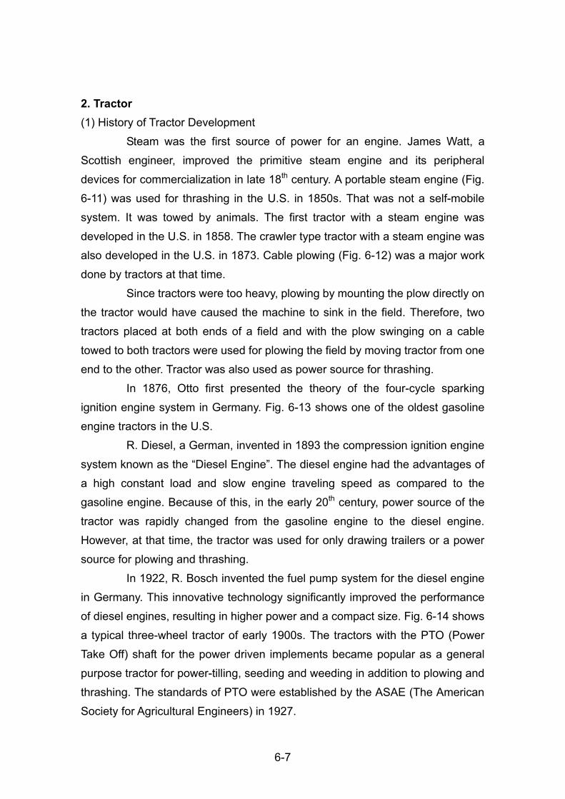
steam-engine tractor made in Canada, which is still able to move. Fig. 6-7 is of a
four-wheel driven tractor of Benz named as a “Unimog”. This tractor belonged to
the Laboratory of Agricultural Machinery, Hokkaido University, and was in use for
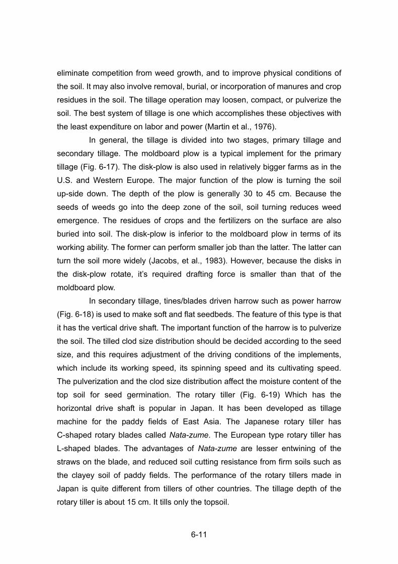
the students’ experiments and laboratory until 20 years ago. We can see a
model of corn cultivation (Fig. 6-8) on the wall of the museum.
Historical Village of Hokkaido (Hokkaido Kaitaku no Mura) located at
Atsubetsu-ku in Sapporo has historical buildings concerning Agriculture. The
breeding house for the silkworm, the European style barn for the sheep and the
balloon frame barn for the cattle are some important structures at the museum,
and these help to understand the modern agriculture system in Hokkaido. For
more details please see the website http://www.kaitaku.or.jp/info/info.htm.
The museum ‘Baron Archives’ (Danshaku Shiryokan) in Hokuto city
near Hakodate city presents the history and the equipments of potato cultivation
used in Hokkaido (Fig. 6-9). Baron Ryokichi Kawata (1856~1951), an engineer
of shipbuilding studied potato production at Oshima-tobetsu district of Kamiiso
town (now Hokuto city). He imported big agricultural machines and equipments
from United States of America and Europe. His farm was one of the biggest
private farms in Hokkaido about 90 years ago. He had an improved variety of
potato “Danshaku-imo”, which is well known in Japan. Mr. Kawata also imported
the oldest steam-engine car from USA, shown in Fig. 6-10.
6-5
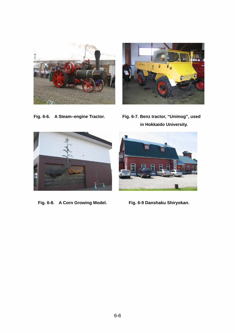
Fig. 6-6. A Steam–engine Tractor. Fig. 6-7. Benz tractor, “Unimog”, used
in Hokkaido University.
Fig. 6-8. A Corn Growing Model. Fig. 6-9 Danshaku Shiryokan.
6-6
2. Tractor (1) History of Tractor Development
Steam was the first source of power for an engine. James Watt, a
Scottish engineer, improved the primitive steam engine and its peripheral
devices for commercialization in late 18th century. A portable steam engine (Fig.
6-11) was used for thrashing in the U.S. in 1850s. That was not a self-mobile
system. It was towed by animals. The first tractor with a steam engine was
developed in the U.S. in 1858. The crawler type tractor with a steam engine was
also developed in the U.S. in 1873. Cable plowing (Fig. 6-12) was a major work
done by tractors at that time.
Since tractors were too heavy, plowing by mounting the plow directly on
the tractor would have caused the machine to sink in the field. Therefore, two
tractors placed at both ends of a field and with the plow swinging on a cable
towed to both tractors were used for plowing the field by moving tractor from one
end to the other. Tractor was also used as power source for thrashing.
In 1876, Otto first presented the theory of the four-cycle sparking
ignition engine system in Germany. Fig. 6-13 shows one of the oldest gasoline
engine tractors in the U.S.
R. Diesel, a German, invented in 1893 the compression ignition engine
system known as the “Diesel Engine”. The diesel engine had the advantages of
a high constant load and slow engine traveling speed as compared to the
gasoline engine. Because of this, in the early 20th century, power source of the
tractor was rapidly changed from the gasoline engine to the diesel engine.
However, at that time, the tractor was used for only drawing trailers or a power
source for plowing and thrashing.
In 1922, R. Bosch invented the fuel pump system for the diesel engine
in Germany. This innovative technology significantly improved the performance
of diesel engines, resulting in higher power and a compact size. Fig. 6-14 shows
a typical three-wheel tractor of early 1900s. The tractors with the PTO (Power
Take Off) shaft for the power driven implements became popular as a general
purpose tractor for power-tilling, seeding and weeding in addition to plowing and
thrashing. The standards of PTO were established by the ASAE (The American
Society for Agricultural Engineers) in 1927.
6-7

Fig. 6-10. The Oldest Steam-engine Car. Fig. 6-11. Portable Steam Engine
(1849).
Fig. 6-12. Cable Plowing (English, 1859).
Fig. 6-13. Froelich Tractor (1892). Fig. 6-14. McCormic Deering Farmall
Tractor (1924).
6-8

The other two important innovative technologies regarding tractor
development were the installation of the rubber air tire (Fig. 6-15), and the
hydraulic three-point hitching system. The rubber air tire was invented by J.
Dunlop in 1877. The hydraulic three-point hitching system was invented by
Massey Ferguson Company in Great Britain in 1935. Tractor became a multi
purpose vehicle for drawing trailers as well as driving mounted type agricultural
implements. The installation ratio of the rubber air tires in the market of tractors
had been more than 95 % until 1940.
(2) Present Tractors
Fig. 6-16 is a typical style of the present tractor with four-wheel drive
system (4WD). The turbo charged diesel engine is of 3,989 cc with a
four-cylinder water cooled system, and 95 PS (69.9 kW)/2,200 rpm. The weight
is 3,510 kg. The current biggest tractor in the world has 350 PS (257.3 kW).
It is equipped with many electrical controls for operation. For example,
the hydraulic steering control, the hydraulic three-point hitching control including
draft-control for plowing and the level and depth controls for the rotary tiller,
all-speed governor for the constant engine speed control, the shifting system for
transmission, and the hydraulic assist pedals. All electronic functions are
controlled by a computer. Furthermore, the automatic air-conditioning system
and the radio are installed in the cabin to let the driver do his/her job comfortably.
It thus differs from the classic tractor of McCormic Deering to a great extent (Fig.
6-4).
The tractor size is identified by the “horse power” of the engine. The
required horse power is strongly related to the field size. The average tractor
size is about 25 PS (18.4 kW) for paddy farming in Honshu island, whereas for
the upland farm in Hokkaido, it is about 75 PS (55.1 kW). It is about 150 PS
(110.3 kW) in the Great Plains of the U.S. The tractor size also vary for the
different operations of crop cultivation.
3. Agricultural Machinery for different operations (1) Tillage
The objectives of soil tillage are to prepare a suitable seedbed, to
6-9

Fig. 6-15. Allis-Chalmers B Tractor (1938).
Fig. 6-16. Iseki Tractor T-950 (95 PS, 1997).
6-10
eliminate competition from weed growth, and to improve physical conditions of
the soil. It may also involve removal, burial, or incorporation of manures and crop
residues in the soil. The tillage operation may loosen, compact, or pulverize the
soil. The best system of tillage is one which accomplishes these objectives with
the least expenditure on labor and power (Martin et al., 1976).
In general, the tillage is divided into two stages, primary tillage and
secondary tillage. The moldboard plow is a typical implement for the primary
tillage (Fig. 6-17). The disk-plow is also used in relatively bigger farms as in the
U.S. and Western Europe. The major function of the plow is turning the soil
up-side down. The depth of the plow is generally 30 to 45 cm. Because the
seeds of weeds go into the deep zone of the soil, soil turning reduces weed
emergence. The residues of crops and the fertilizers on the surface are also
buried into soil. The disk-plow is inferior to the moldboard plow in terms of its
working ability. The former can perform smaller job than the latter. The latter can
turn the soil more widely (Jacobs, et al., 1983). However, because the disks in
the disk-plow rotate, it’s required drafting force is smaller than that of the
moldboard plow.
In secondary tillage, tines/blades driven harrow such as power harrow
(Fig. 6-18) is used to make soft and flat seedbeds. The feature of this type is that
it has the vertical drive shaft. The important function of the harrow is to pulverize
the soil. The tilled clod size distribution should be decided according to the seed
size, and this requires adjustment of the driving conditions of the implements,
which include its working speed, its spinning speed and its cultivating speed.
The pulverization and the clod size distribution affect the moisture content of the
top soil for seed germination. The rotary tiller (Fig. 6-19) Which has the
horizontal drive shaft is popular in Japan. It has been developed as tillage
machine for the paddy fields of East Asia. The Japanese rotary tiller has
C-shaped rotary blades called Nata-zume. The European type rotary tiller has
L-shaped blades. The advantages of Nata-zume are lesser entwining of the
straws on the blade, and reduced soil cutting resistance from firm soils such as
the clayey soil of paddy fields. The performance of the rotary tillers made in
Japan is quite different from tillers of other countries. The tillage depth of the
rotary tiller is about 15 cm. It tills only the topsoil.
6-11
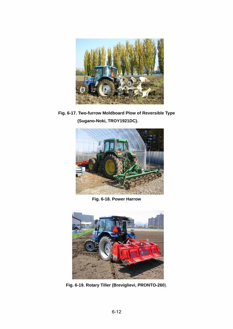
Fig. 6-17. Two-furrow Moldboard Plow of Reversible Type
(Sugano-Noki, TROY1921DC).
Fig. 6-18. Power Harrow
Fig. 6-19. Rotary Tiller (Breviglievi, PRONTO-260).
6-12

In Hokkaido, plowing is done in late autumn, while rotary tillers or the
power harrows are used for making seedbed of fine soil in spring. Since snow
melting on the ground surface generally starts in the middle of April, farmers do
not have enough time for both primary and secondary tillage before seeding.
Two to three weeks are required for tillage.
(2) Sowing Implements
The general seeding mechanism operates as follow: (i) the double disk
openers make the furrow, (ii) the seed is placed, (iii) the soil covering device
close the furrow, and (iv) the press wheel compacts the surface soil. The seeder
with fertilizer applicator (Fig. 6-20) is popular for sowing beans, corn and sugar
beet. The combination of implements saves time. The seeder releases seeds
using the vacuum aeration mechanism. It ensures good seeding keeping
constant distance between seeds, and proper seeding depth. Fertilizer
applicator is attached to most of the seeders and seeding implements. The
variable rate control system for dusting or spraying fertilizers has been
developed.
The drill is used for sowing of wheat, barley and grass, and planter for
transplanting potatoes and nursery. Special transplanters with unique
mechanisms are available for transplanting nurseries of sugar beet, carrots,
onions and other vegetables. This advanced technology promotes sustainable
and environment friendly agriculture.
(3) Weed, Insect and Disease Control Implements
Fig. 6-21 shows a sprayer attached to a utility vehicle having 14.5 PS
(10.7 kW), four-wheel drive and four-wheel steering system (4WS). It is possible
to attach a rotary weeding system to this vehicle, and this can be used for both
upland and paddy fields because of its high ground clearance. It is used for
spraying chemicals against weeds, insects and diseases. The swirl nozzle is
commonly used to produce minute particles of spray. The tine-type weeding machine is used for mechanical weeding.
Mechanical weeding reduces the use of chemicals, and thus promotes the
production of organic and safer agricultural products. The weeding machine
6-13

Fig. 6-20. Air Seeder with Fertilizer for Four-rows (Tabata, TJEVS-4LR).
Fig. 6-21. Utility Vehicle (Sprayer Version, Iseki JK-14).
6-14

(Fig. 6-22) has special rotating tines for weeding between rows and also
between plants in a row. However, it requires high operational skills, and
weeding needs to be done every week. Mechanical weeding system has lower
working speed and weed removal performance.
(4) Harvester
There are different types of harvesters for various crops. Fig. 6-23
shows self-propelled combine harvester for wheat, beans, corn and other grain
crops. The combine cuts the crop, feeds the crop to the thrashing cylinder,
thrashes the seeds/grains from the seed head, separates the seeds/grains from
the straw, cleans the seeds/grains, and handles the clean seeds/grains until
these are loaded into a truck or trailer for transportation (Jacobs, et al., 1983).
The word “combine” means the combination of the cutting and thrashing devices.
The cutting head of the cutter and the pickup reel need to be replaced for
different crops. The standard harvesting width is about 5 m. The Berry Company
in the U.S. built the first self-propelled combine harvester with the straw-burning
steam engine in 1866.
Fig. 6-24 is of a potato harvester. The blade of the harvester digs the
potato tubers, and the tubers and soil are separated through several ladder
conveyers to a storage tank. The workers on the harvester sort good tubers from
green and damaged ones, and clods.
Since every crop requires different harvesting mechanism, farmers
prepare harvesters for the various crops they cultivate, although a harvester is
used only for one to two weeks in a year. Many types of harvesters have been
developed, for example, for sugar beet, radish, lettuce, onion, cabbage, tomato,
carrot etc. (Fig. 6-25).
(5) Forage cultivation
1) Hay production
Previously, cube bale was used in haymaking. Now, roll bale is used.
The roll bale is better than cube bale because the harvesting speed of the
harvester can be increased. Since roll bale is larger than a cube bale, the
number of bales is lower. Transportation and handling operations are reduced
6-15

Fig. 6-22. Weeding Machine (Nichinoki-Seiko, NAK-5).
Fig. 6-23. Combine Harvester (New Holland, CS-540).
Fig. 6-24. Potato Harvester (Toyo-noki).
6-16

thereby saving time and labor (Culpin, 1975).
The hay harvesting involves cutting the grass using a mower (Fig. 6-26),
turning it over for thorough drying using a gyro-type hay tedder (Fig. 6-27),
making the windrows using a rake and making the roll bale using a roll baler (Fig.
6-28).
2) Silage production
Silage is a high protein feed produced from grasses and crops for the
livestock. Grass silage is produced by wrapping roll bales in plastic films using
wrapping machine. Fig. 6-29 shows the roll baler with the wrapping machine.
This combined machine system has become popular because it saves time
and cost. The roll bales wrapped with plastic films start fermenting and result in
grass silages due to the action of lactic acid. The materials are covered with the
plastic sheet to avoid aeration for production of good amount of lactic acid by
fermentation. This methodology is preferred than the sealed tower silo method
because it can be adapted to variable quantities of grasses and crops, and
also involves less work for loading and unloading operations.
Corn for silage is harvested by the forage harvester, shown in Fig. 6-30.
The forage harvester chops both stalk and leaves of the corn. The wagon track
or the wagon towed by a tractor should run in parallel to the harvester to
temporarily store the harvested material before the harvested corns are put into
the bunker silo. The bunker silo is easier to use and maintain than tower silo.
References
Culpin C. (1975) Profitable Farm Mechanization, Crosby Lockwood Staples.
Jacobs C. and W. Harrell (1983) Agricultural Power and Machinery, McGraw-Hill
Book Company.
Martin J. H, W. H. Leonard and D. L. Stamp (1976) Principles of Field Crop
Production, Macmillan Publishing.
6-17

Fig. 6-25. Carrot Harvester (Kubota). Fig. 6-26. Mower.
Fig. 6-27. Gyro-Tedder. Fig. 6-28. Roll Baler.
Fig. 6-29. Roll Baler with Rapping Fig. 6-30. Forage Harvester Mounted
Machine System. on Tractor.
6-18