agreement - unece homepage€¦ · · 2013-01-14e /ece/trans/505/rev.2/add.116/rev.2/amend.1...
TRANSCRIPT

E/ECE/324/Rev.2/Add.116/Rev.2/Amend.1 −E/ECE/TRANS/505/Rev.2/Add.116/Rev.2/Amend.1
GE.12-
Agreement
Concerning the adoption of uniform technical prescriptions for wheeled
vehicles, equipment and parts which can be fitted and/or be used on
wheeled vehicles and the conditions for reciprocal recognition of
approvals granted on the basis of these prescriptions*
(Revision 2, including the amendments which entered into force on 16 October 1995)
Addendum 116: Regulation No. 117
Revision 2 – Amendment 1
Supplement 1 to the 02 series of amendments - Date of entry into force: 18 November 2012
Uniform provisions concerning the approval of tyres with regard to
rolling sound emissions and to adhesion on wet surfaces
UNITED NATIONS
* Former title of the Agreement: Agreement Concerning the Adoption of Uniform Conditions of
Approval and Reciprocal Recognition of Approval for Motor Vehicle Equipment and Parts, done at
Geneva on 20 March 1958.
6 December 2012

E/ECE/324/Rev.2/Add.116/Rev.2/Amend.1
E/ECE/TRANS/505/Rev.2/Add.116/Rev.2/Amend.1
2
Contents, amend to read:
…
Annexes
…
5 Testing method for measuring the wet grip index (G) of C1 tyres ...................................................
Appendix – Test reports examples of wet grip index .......................................................................
7 ... .........................................................................................................................................
… .........................................................................................................................................
Appendix – Test reports and test data for C3 tyres ..........................................................................
Paragraph 2.16., amend to read:
"2.16. "Standard reference test tyre" (SRTT) means a tyre that is produced,
controlled and stored in accordance with the ASTM (American Society for
Testing and Materials) standards
(a) E1136-93 (2003) for the size P195/75R14
(b) F2871 (2011) for the size 245/70R19.5
(c) F2870 (2011) for the size 315/70R22.5."
Paragraph 2.17., amend to read:
"2.17. Wet Grip or Snow Grip measurements – Specific definitions"
Paragraph 2.17.3., amend to read:
"2.17.3. "Control tyre" means a normal production tyre that is used to establish the
wet grip or snow grip performance of tyre sizes unable to be fitted to the
same vehicle as the standard reference test tyre – see paragraph 4.1.7. of
Annex 5 and paragraph 3.4.3. of Annex 7 to this Regulation."
Insert new paragraph 2.17.5., to read:
"2.17.5. "Snow grip index ("SG")" means the ratio between the performance of the
candidate tyre and the performance of the standard reference test tyre."
Paragraphs 2.17.5. (former) to 2.17.7., renumber as paragraphs 2.17.6. to 2.17.8.
Paragraph 6.4., amend to read:
"6.4. In order to be classified in the category of use "snow tyre", a tyre is required
to meet performance requirements based on a test method by which:
(a) the mean fully developed deceleration ("mfdd") in a braking test,
(b) or alternatively an average traction force in a traction test,
(c) or alternatively the average acceleration in an acceleration test
of a candidate tyre is compared to that of a standard reference tyre.
The relative performance shall be indicated by a snow index."
Paragraph 6.4.1.1., amend to read:
"6.4.1.1. Class C1, C2 and C3 tyres
The minimum snow index value, as calculated in the procedure described in
Annex 7 and compared with the SRTT shall be as follows:

E/ECE/324/Rev.2/Add.116/Rev.2/Amend.1
E/ECE/TRANS/505/Rev.2/Add.116/Rev.2/Amend.1
3
Class
of tyre
Snow gripe index
(brake on snow method) (a)
Snow grip index
(spin traction method) (b)
Snow grip index
(acceleration method) (c)
Ref. = C1 – SRTT 14 Ref. = C1 – SRTT 14 Ref. = C3N – SRTT 19.5
Ref. = C3W – SRTT 22.5
C1 1.07 1.10 No
C2 No 1.10 No
C3 No No 1.25
(a) See paragraph 3. of Annex 7 to this Regulation (b) See paragraph 2. of Annex 7 to this Regulation (c) See paragraph 4. of Annex 7 to this Regulation "
Annex 5 and its Appendix, amend to read:
"Annex 5
Testing method for measuring the wet grip index (G) of C1 tyres
1. Reference standards
The following documents listed apply.
1.1. ASTM E 303-93 (Reapproved 2008), Standard Test Method for Measuring
Surface Frictional Properties Using the British Pendulum Tester.
1.2. ASTM E 501-08, Standard Specification for Standard Rib Tire for Pavement
Skid-Resistance Tests.
1.3. ASTM E 965-96 (Reapproved 2006), Standard Test Method for Measuring
Pavement Macrotexture Depth Using a Volumetric Technique.
1.4. ASTM E 1136-93 (Reapproved 2003), Standard Specification for a Radial
Standard Reference Test Tire P195/75R14.
1.5. ASTM F 2493-08, Standard Specification for a Radial Standard Reference
Test Tire P225/60R16.
2. Definitions
For the purposes of testing wet grip of C1 tyres:
2.1. "Test run" means a single pass of a loaded tyre over a given test track
surface.
2.2. "Test tyre(s)" means a candidate tyre, a reference tyre or a control tyre or tyre
set that is used in a test run.
2.3. "Candidate tyre(s) (T)" means a tyre or a tyre set that is tested for the purpose
of calculating its wet grip index.
2.4. "Reference tyre(s) (R)" means a tyre or a tyre set that has the characteristics
indicated in the ASTM F 2493-08 and referred to as the Standard Reference
Test Tyre.

E/ECE/324/Rev.2/Add.116/Rev.2/Amend.1
E/ECE/TRANS/505/Rev.2/Add.116/Rev.2/Amend.1
4
2.5. "Control tyre(s) (C)" means an intermediate tyre or a set of intermediate tyres
which is used when the candidate tyre and the reference tyre cannot be
directly compared on the same vehicle.
2.6. "Braking force of a tyre" means the longitudinal force, expressed in newton,
resulting from braking torque application.
2.7. "Braking force coefficient of a tyre (BFC)" means the ratio of the braking
force to the vertical load.
2.8. "Peak braking force coefficient of a tyre" means the maximum value of a tyre
braking force coefficient that occurs prior to wheel lockup as the braking
torque is progressively increased.
2.9. "Lockup of a wheel" means the condition of a wheel in which its rotational
velocity about the wheel spin axis is zero and it is prevented from rotating in
the presence of applied wheel torque.
2.10. "Vertical load" means the load in newton imposed on the tyre perpendicular
to the road surface.
2.11. "Tyre test vehicle" means a dedicated special purpose vehicle which has
instruments to measure the vertical and the longitudinal forces on one test
tyre during braking.
2.12. "SRTT14" means the ASTM E 1136-93 (Reapproved 2003), Standard
Specification for a Radial Standard Reference Test Tire P195/75R14.
2.13. "SRTT16" means the ASTM F 2493-08, Standard Specification for a Radial
Standard Reference Test Tire P225/60R16.
3. General test conditions
3.1. Track characteristics
The test track shall have the following characteristics:
3.1.1. The surface shall have a dense asphalt surface with a uniform gradient of not
more than 2 per cent and shall not deviate more than 6 mm when tested with
a 3 m straight edge.
3.1.2. The surface shall have a pavement of uniform age, composition, and wear.
The test surface shall be free of loose material and foreign deposits.
3.1.3. The maximum chipping size shall be 10 mm (tolerances permitted from 8
mm to 13 mm).
3.1.4. The texture depth as measured by a sand patch shall be 0.7 ± 0.3 mm. It shall
be measured in accordance with ASTM E 965-96 (Reapproved 2006).
3.1.5. The wetted frictional properties of the surface shall be measured with either
method (a) or (b) in section 3.2.
3.2. Methods to measure the wetted frictional properties of the surface
3.2.1. British Pendulum Number (BPN) method (a)
The British Pendulum Number method shall be as defined in ASTM E 303-93
(Reapproved in 2008).
Pad rubber component formulation and physical properties shall be as
specified in ASTM E 501-08.

E/ECE/324/Rev.2/Add.116/Rev.2/Amend.1
E/ECE/TRANS/505/Rev.2/Add.116/Rev.2/Amend.1
5
The averaged British Pendulum Number (BPN) shall be between 42 and
60 BPN after temperature correction as follows.
BPN shall be corrected by the wetted road surface temperature. Unless
temperature correction recommendations are indicated by the British
pendulum manufacturer, the following formula is used:
BPN = BPN(measured value) + temperature correction
temperature correction = -0.0018 t 2 + 0.34 t - 6.1
where t is the wetted road surface temperature in degrees Celsius.
Effects of slider pad wear: the pad shall be removed for maximum wear when
the wear on the striking edge of the slider reaches 3.2 mm in the plane of the
slider or 1.6 mm vertical to it in accordance with section 5.2.2. and Figure 3
of ASTM E 303-93 (Reapproved 2008).
For the purpose of checking track surface BPN consistency for the
measurement of wet grip on an instrumented passenger car: the BPN values
of the test track should not vary over the entire stopping distance so as to
decrease the dispersion of test results. The wetted frictional properties of the
surface shall be measured five times at each point of the BPN measurement
every 10 meters and the coefficient of variation of the averaged BPN shall
not exceed 10 per cent.
3.2.2. ASTM E 1136 Standard Reference Test Tyre method (b)
By derogation with paragraph 2.4., this method uses the reference tyre that
has the characteristics indicated in the ASTM E 1136-93 (Reapproved 2003)
and referred to as SRTT14.
The average peak braking force coefficient (µpeak,ave) of the SRTT14 shall be
0.7 ± 0.1 at 65 km/h.
The average peak braking force coefficient (µpeak,ave) of the SRTT14 shall be
corrected for the wetted road surface temperature as follows:
Peak braking force coefficient (µpeak,ave) = peak braking force coefficient
(measured) + temperature correction
Temperature correction = 0.0035 x (t - 20)
Where t is the wetted road surface temperature in degrees Celsius.
3.3. Atmospheric conditions
The wind conditions shall not interfere with wetting of the surface (wind-
shields are allowed).
Both the wetted surface temperature and the ambient temperature shall be
between 2 °C and 20 °C for snow tyres and 5 °C and 35 °C for normal tyres.
The wetted surface temperature shall not vary during the test by more than
10 °C.
The ambient temperature must remain close to the wetted surface
temperature; the difference between the ambient and the wetted surface
temperatures must be less than 10 °C.
E/ECE/324/Rev.2/Add.116/Rev.2/Amend.1
E/ECE/TRANS/505/Rev.2/Add.116/Rev.2/Amend.1
6
4. Testing methods for measuring wet grip
For the calculation of the wet grip index (G) of a candidate tyre, the wet grip
braking performance of the candidate tyre is compared to the wet grip
braking performance of the reference tyre on a vehicle travelling straight
ahead on a wet, paved surface. It is measured with one of the following
methods:
(a) Vehicle method consisting of testing a set of tyres mounted on an
instrumented passenger car;
(b) Testing method using a trailer towed by a vehicle or a tyre test
vehicle, equipped with the test tyre(s).
4.1. Testing method (a) using an instrumented passenger car
4.1.1. Principle
The testing method covers a procedure for measuring the deceleration
performance of C1 tyres during braking, using an instrumented passenger car
equipped with an Antilock Braking System (ABS), where "instrumented
passenger car" means a passenger car that is fitted with the measuring
equipment listed in section 4.1.2.2. for the purpose of this testing method.
Starting with a defined initial speed, the brakes are applied hard enough on
four wheels at the same time to activate the ABS. The average deceleration is
calculated between two pre-defined speeds.
4.1.2. Equipment
4.1.2.1. Vehicle
Permitted modifications on the passenger car are as follows:
(a) Those allowing the number of tyre sizes that can be mounted on the
vehicle to be increased;
(b) Those permitting automatic activation of the braking device to be
installed;
(c) Any other modification of the braking system is prohibited.
4.1.2.2. Measuring equipment
The vehicle shall be fitted with a sensor suitable for measuring speed on a
wet surface and distance covered between two speeds.
To measure vehicle speed, a fifth wheel or non-contact speed-measuring
system shall be used.
4.1.3. Conditioning of the test track and wetting condition
The test track surface shall be watered at least half an hour prior to testing in
order to equalize the surface temperature and water temperature. External
watering should be supplied continuously throughout testing. For the whole
testing area, the water depth shall be 1.0 ± 0.5 mm, measured from the peak
of the pavement.
The test track should then be conditioned by conducting at least ten test runs
with tyres not involved in the test programme at 90 km/h.

E/ECE/324/Rev.2/Add.116/Rev.2/Amend.1
E/ECE/TRANS/505/Rev.2/Add.116/Rev.2/Amend.1
7
4.1.4. Tyres and rims
4.1.4.1. Tyre preparation and break-in
The test tyres shall be trimmed to remove all protuberances on the tread
surface caused by mould air vents or flashes at mould junctions.
The test tyres shall be mounted on the test rim declared by the tyre
manufacturer.
A proper bead seat should be achieved by the use of a suitable lubricant.
Excessive use of lubricant should be avoided to prevent slipping of the tyre
on the wheel rim.
The test tyres/rim assemblies shall be stored in a location for a minimum of
two hours such that they all have the same ambient temperature prior to
testing. They should be shielded from the sun to avoid excessive heating by
solar radiation.
For tyre break-in, two braking runs shall be performed.
4.1.4.2. Tyre load
The static load on each axle tyre shall lie between 60 per cent and 90 per cent
of the tested tyre load capacity. Tyre loads on the same axle should not differ
by more than 10 per cent.
4.1.4.3. Tyre inflation pressure
On the front and rear axles, the inflation pressures shall be 220 kPa (for
standard- and extra-load tyres). The tyre pressure should be checked just
prior to testing at ambient temperature and adjusted if required.
4.1.5. Procedure
4.1.5.1. Test run
The following test procedure applies for each test run.
4.1.5.1.1. The passenger car is driven in a straight line up to 85 ± 2 km/h.
4.1.5.1.2. Once the passenger car has reached 85 ± 2 km/h, the brakes are always
activated at the same place on the test track referred to as "braking starting
point", with a longitudinal tolerance of 5 m and a transverse tolerance of
0.5 m.
4.1.5.1.3. The brakes are activated either automatically or manually.
4.1.5.1.3.1. The automatic activation of the brakes is performed by means of a detection
system made of two parts, one indexed to the test track and one on board the
passenger car.
4.1.5.1.3.2. The manual activation of the brakes depends on the type of transmission as
follows. In both cases, a minimum of 600 N pedal efforts is required.
For manual transmission, the driver should release the clutch and depress the
brake pedal sharply, holding it down as long as necessary to perform the
measurement.
For automatic transmission, the driver should select neutral gear and then
depress the brake pedal sharply, holding it down as long as necessary to
perform the measurement.

E/ECE/324/Rev.2/Add.116/Rev.2/Amend.1
E/ECE/TRANS/505/Rev.2/Add.116/Rev.2/Amend.1
8
4.1.5.1.4. The average deceleration is calculated between 80 km/h and 20 km/h.
If any of the specifications listed above (including speed tolerance,
longitudinal and transverse tolerance for the braking starting point, and
braking time) are not met when a test run is made, the measurement is
discarded and a new test run is made.
4.1.5.2. Test cycle
A number of test runs are made in order to measure the wet grip index of a
set of candidate tyres (T) according to the following procedure, whereby each
test run shall be made in the same direction and up to three different sets of
candidate tyres may be measured within the same test cycle:
4.1.5.2.1. First, the set of reference tyres are mounted on the instrumented passenger
car.
4.1.5.2.2. After at least three valid measurements have been made in accordance with
section 4.1.5.1., the set of reference tyres is replaced by a set of candidate
tyres.
4.1.5.2.3. After six valid measurements of the candidate tyres are performed, two more
sets of candidate tyres may be measured.
4.1.5.2.4. The test cycle is closed by three more valid measurements of the same set of
reference tyres as at the beginning of the test cycle.
Examples:
(a) The run order for a test cycle of three sets of candidate tyres (T1 to
T3) plus a set of reference tyres (R) would be the following:
R-T1-T2-T3-R
(b) The run order for a test cycle of five sets of candidate tyres (T1 to T5)
plus a set of reference tyres (R) would be the following:
R-T1-T2-T3-R-T4-T5-R
4.1.6. Processing of measurement results
4.1.6.1. Calculation of the average deceleration (AD)
The average deceleration (AD) is calculated for each valid test run in m/s2
as
follows:
where:
Sf is the final speed in m/s; Sf = 20 km/h = 5.556 m/s
Si is the initial speed in m/s; Si = 80 km/h = 22.222 m/s
d is the distance covered between Si and Sf in metre.
4.1.6.2. Validation of results
The AD coefficient of variation is calculated as follows:
(Standard Deviation / Average) x 100.
d
S S AD
i f
2
2 2

E/ECE/324/Rev.2/Add.116/Rev.2/Amend.1
E/ECE/TRANS/505/Rev.2/Add.116/Rev.2/Amend.1
9
For the reference tyres (R): If the AD coefficient of variation of any two
consecutive groups of three tests runs of the reference tyre set is higher than
3 per cent, all data should be discarded and the test repeated for all test tyres
(the candidate tyres and the reference tyres).
For the candidate tyres (T): The AD coefficients of variation are calculated
for each candidate tyre set. If one coefficient of variation is higher than 3 per
cent, the data should be discarded and the test repeated for that candidate tyre
set.
4.1.6.3. Calculation of adjusted average deceleration (Ra)
The average deceleration (AD) of the reference tyre set used for the
calculation of its braking force coefficient is adjusted according to the
positioning of each candidate tyre set in a given test cycle.
This adjusted AD of the reference tyre (Ra) is calculated in m/s2
in
accordance with Table 1 where R1 is the average of the AD values in the first
test of the reference tyre set (R) and R2 is the average of the AD values in the
second test of the same reference tyre set (R).
Table 1
Number of sets of candidate
tyres within one test cycle
Set of candidate tyres Ra
1
(R1-T1-R2)
T1 Ra = 1/2 (R1 + R2)
2
(R1-T1-T2-R2)
T1 Ra = 2/3 R1 + 1/3 R2
T2 Ra = 1/3 R1 + 2/3 R2
3
(R1-T1-T2-T3-R2)
T1 Ra = 3/4 R1 + 1/4 R2
T2 Ra = 1/2 (R1 +R2)
T3 Ra = 1/4 R1 + 3/4 R2
4.1.6.4. Calculation of the braking force coefficient (BFC)
The braking force coefficient (BFC) is calculated for a braking on the two
axles according to Table 2 where Ta (a = 1, 2 or 3) is the average of the AD
values for each candidate tyre (T) set that is part of a test cycle.
Table 2
Test Tyre Braking force coefficient
Reference tyre BFC(R) = │Ra/g│
Candidate tyre BFC(T) = │Ta/g│
g is the acceleration due to gravity, g = 9.81 m/s2
4.1.6.5. Calculation of the wet grip index of the candidate tyre
The wet grip index of the candidate tyre (G(T)) is calculated as follows:

E/ECE/324/Rev.2/Add.116/Rev.2/Amend.1
E/ECE/TRANS/505/Rev.2/Add.116/Rev.2/Amend.1
10
where:
t is the measured wet surface temperature in degree Celsius when the
candidate tyre (T) is tested
t0 is the wet surface reference temperature condition, t0 = 20 °C for normal
tyres and t0 = 10 °C for snow tyres
BFC(R0) is the braking force coefficient for the reference tyre in the
reference conditions, BFC(R0) = 0.68
a = -0.4232 and b = -8.297 for normal tyres, a = 0.7721 and b = 31.18 for
snow tyres [a is expressed as (1/°C)]
4.1.7. Wet grip performance comparison between a candidate tyre and a reference
tyre using a control tyre
4.1.7.1. General
Where the candidate tyre size is significantly different from that of the
reference tyre, a direct comparison on the same instrumented passenger car
may not be possible. This testing method uses an intermediate tyre,
hereinafter called the control tyre as defined in paragraph 2.5.
4.1.7.2. Principle of the approach
The principle is the use of a control tyre set and two different instrumented
passenger cars for the test cycle of a candidate tyre set in comparison with a
reference tyre set.
One instrumented passenger car is fitted with the reference tyre set followed
by the control tyre set, the other with the control tyre set followed by the
candidate tyre set.
The specifications listed in sections 4.1.2. to 4.1.4. apply.
The first test cycle is a comparison between the control tyre set and the
reference tyre set.
The second test cycle is a comparison between the candidate tyre set and the
control tyre set. It is done on the same test track and during the same day as
the first test cycle. The wetted surface temperature shall be within ±5 °C of
the temperature of the first test cycle. The same control tyre set shall be used
for the first and the second test cycles.
The wet grip index of the candidate tyre (G(T)) is calculated as follows:
G(T) = G1 × G2
where:
G1 is the relative wet grip index of the control tyre (C) compared to the
reference tyre (R) calculated as follows:
-2
0 0 1
10 . 1 ) (
) ( ) ( 125
) (
) (
R BFC
R BFC b t t a
R BFC
C BFC G 0
2
0 0
10 0 , 1 ) (
) ( ) ( 125
) (
) ( ) (
R BFC
R BFC b t t a
R BFC
T BFC T G

E/ECE/324/Rev.2/Add.116/Rev.2/Amend.1
E/ECE/TRANS/505/Rev.2/Add.116/Rev.2/Amend.1
11
G2 is the relative wet grip index of the candidate tyre (T) compared to the
control tyre (C) calculated as follows:
4.1.7.3. Storage and preservation
It is necessary that all the tyres of a control tyre set have been stored in the
same conditions. As soon as the control tyre set has been tested in
comparison with the reference tyre, the specific storage conditions defined in
ASTM E 1136-93 (Reapproved 2003) shall be applied.
4.1.7.4. Replacement of reference tyres and control tyres
When irregular wear or damage results from tests, or when wear influences
the test results, the use of the tyre shall be discontinued.
4.2. Testing method (b) using a trailer towed by a vehicle or a tyre test vehicle
4.2.1. Principle
The measurements are conducted on test tyres mounted on a trailer towed by
a vehicle (hereafter referred to as tow vehicle) or on a tyre test vehicle. The
brake in the test position is applied firmly until sufficient braking torque is
generated to produce the maximum braking force that will occur prior to
wheel lockup at a test speed of 65 km/h.
4.2.2. Equipment
4.2.2.1. Tow vehicle and trailer or tyre test vehicle
The tow vehicle or the tyre test vehicle shall have the capability of
maintaining the specified speed of 65 ± 2 km/h even under the maximum
braking forces.
The trailer or the tyre test vehicle shall be equipped with one place where the
tyre can be fitted for measurement purposes hereafter called 'test position' and
the following accessories:
(a) Equipment to activate brakes in the test position;
(b) A water tank to store sufficient water to supply the road surface
wetting system, unless external watering is used;
(c) Recording equipment to record signals from transducers installed at
the test position and to monitor water application rate if the self-
watering option is used.
The maximum variation of toe-settings and camber angle for the test position
shall be within ±0.5° with maximum vertical load. Suspension arms and
bushings shall have sufficient rigidity necessary to minimize free play and
ensure compliance under application of maximum braking forces. The
suspension system shall provide adequate load-carrying capacity and be of
such a design as to isolate suspension resonance.
The test position shall be equipped with a typical or special automotive brake
system which can apply sufficient braking torque to produce the maximum
value of braking test wheel longitudinal force at the conditions specified.
) ( 2 C BFC
BFC G
( T )

E/ECE/324/Rev.2/Add.116/Rev.2/Amend.1
E/ECE/TRANS/505/Rev.2/Add.116/Rev.2/Amend.1
12
The brake application system shall be able to control the time interval
between initial brake application and peak longitudinal force as specified in
section 4.2.7.1.
The trailer or the tyre test vehicle shall be designed to accommodate the
range of candidate tyre sizes to be tested.
The trailer or the tyre test vehicle shall have provisions for adjustment of
vertical load as specified in section 4.2.5.2.
4.2.2.2. Measuring equipment
The test wheel position on the trailer or the tyre test vehicle shall be equipped
with a rotational wheel velocity measuring system and with transducers to
measure the braking force and vertical load at the test wheel.
General requirements for measurement system: The instrumentation system
shall conform to the following overall requirements at ambient temperatures
between 0 °C and 45 °C:
(a) Overall system accuracy, force: ±1.5 per cent of the full scale of the
vertical load or braking force;
(b) Overall system accuracy, speed: ±1.5 per cent of speed or ±1.0 km/h,
whichever is greater.
Vehicle speed: To measure vehicle speed, a fifth wheel or non-contact
precision speed-measuring system should be used.
Braking forces: The braking force-measuring transducers shall measure
longitudinal force generated at the tyre–road interface as a result of brake
application within a range from 0 per cent to at least 125 per cent of the
applied vertical load. The transducer design and location shall minimize
inertial effects and vibration-induced mechanical resonance.
Vertical load: The vertical load-measuring transducer shall measure the
vertical load at the test position during brake application. The transducer shall
have the same specifications as described previously.
Signal conditioning and recording system: All signal conditioning and
recording equipment shall provide linear output with necessary gain and data
reading resolution to meet the specified previous requirements. In addition,
the following requirements apply:
(a) The minimum frequency response shall be flat from 0 Hz to 50 Hz
(100 Hz) within ±1 per cent full scale;
(b) The signal-to-noise ratio shall be at least 20/1;
(c) The gain shall be sufficient to permit full-scale display for full-scale
input signal level;
(d) The input impedance shall be at least ten times larger than the output
impedance of the signal source;
(e) The equipment shall be insensitive to vibrations, acceleration, and
changes in ambient temperature.
4.2.3. Conditioning of the test track
The test track should be conditioned by conducting at least ten test runs with
tyres not involved in the test program at 65 ± 2 km/h.

E/ECE/324/Rev.2/Add.116/Rev.2/Amend.1
E/ECE/TRANS/505/Rev.2/Add.116/Rev.2/Amend.1
13
4.2.4. Wetting conditions
The tow vehicle and trailer or the tyre test vehicle may be optionally
equipped with a pavement-wetting system, less the storage tank, which, in the
case of the trailer, is mounted on the tow vehicle. The water being applied to
the pavement ahead of the test tyres shall be supplied by a nozzle suitably
designed to ensure that the water layer encountered by the test tyre has a
uniform cross section at the test speed with a minimum splash and overspray.
The nozzle configuration and position shall ensure that the water jets are
directed towards the test tyre and pointed towards the pavement at an angle of
20° to 30°.
The water shall strike the pavement 250 mm to 450 mm ahead of the centre
of tyre contact. The nozzle shall be located 25 mm above the pavement or at
the minimum height required to clear obstacles which the tester is expected to
encounter, but in no case more than 100 mm above the pavement.
The water layer shall be at least 25 mm wider than the test tyre tread and
applied so the tyre is centrally located between the edges. Water delivery rate
shall ensure a water depth of 1.0 ± 0.5 mm and shall be consistent throughout
the test to within ±10 per cent. The volume of water per unit of wetted width
shall be directly proportional to the test speed. The quantity of water applied
at 65 km/h shall be 18 l/s per meter of width of wetted surface in case of a
water depth of 1.0 mm.
4.2.5. Tyres and rims
4.2.5.1. Tyre preparation and break-in
The test tyres shall be trimmed to remove all protuberances on the tread
surface caused by mould air vents or flashes at mould junctions.
The test tyre shall be mounted on the test rim declared by the tyre
manufacturer.
A proper bead seat should be achieved by the use of a suitable lubricant.
Excessive use of lubricant should be avoided to prevent slipping of the tyre
on the wheel rim.
The test tyres/rim assemblies shall be stored in a location for a minimum of
two hours such that they all have the same ambient temperature prior to
testing. They should be shielded from the sun to avoid excessive heating by
solar radiation.
For tyre break-in, two braking runs shall be performed under the load,
pressure and speed as specified in paragraphs 4.2.5.2, 4.2.5.3 and 4.2.7.1
respectively.
4.2.5.2. Tyre load
The test load on the test tyre is 75 ± 5 per cent of the tyre load capacity.
4.2.5.3. Tyre inflation pressure
The test tyre cold inflation pressure shall be 180 kPa for standard-load tyres.
For extra-load tyres, the cold inflation pressure shall be 220 kPa.
The tyre pressure should be checked just prior to testing at ambient temperature and
adjusted if required.

E/ECE/324/Rev.2/Add.116/Rev.2/Amend.1
E/ECE/TRANS/505/Rev.2/Add.116/Rev.2/Amend.1
14
4.2.6. Preparation of the tow vehicle and trailer or the tyre test vehicle
4.2.6.1. Trailer
For one axle trailers, the hitch height and transverse position shall be adjusted once the test tyre has been loaded to the specified test load in order to avoid
any disturbance of the measuring results. The longitudinal distance from the
centre line of the articulation point of the coupling to the transverse centre
line of the axle of the trailer shall be at least ten times the "hitch height" or
the "coupling (hitch) height".
4.2.6.2. Instrumentation and equipment
Install the fifth wheel, when used, in accordance with the manufacturer’s
specifications and locate it as near as possible to the mid-track position of the
tow trailer or the tyre test vehicle.
4.2.7. Procedure
4.2.7.1. Test run
The following procedure applies for each test run:
4.2.7.1.1. The tow vehicle or the tyre test vehicle is driven onto the test track in a
straight line at the specified test speed 65 ± 2 km/h.
4.2.7.1.2. The recording system is launched.
4.2.7.1.3. Water is delivered to the pavement ahead of the test tyre approximately 0.5 s
prior to brake application (for internal watering system).
4.2.7.1.4. The trailer brakes are activated within 2 metres of a measurement point of the
wetted frictional properties of the surface and sand depth in accordance with
paragraphs 3.1.4. and 3.1.5 . The rate of braking application shall be such that
the time interval between initial application of force and peak longitudinal
force is in the range 0.2 s to 0.5 s.
4.2.7.1.5. The recording system is stopped.
4.2.7.2. Test cycle
A number of test runs are made in order to measure the wet grip index of the
candidate tyre (T) according to the following procedure, whereby each test
run shall be made from the same spot on the test track and in the same
direction. Up to three candidate tyres may be measured within the same test
cycle, provided that the tests are completed within one day.
4.2.7.2.1. First, the reference tyre is tested.
4.2.7.2.2. After at least six valid measurements are performed in accordance with
section 4.2.7.1., the reference tyre is replaced by the candidate tyre.
4.2.7.2.3. After six valid measurements of the candidate tyre are performed, two more
candidate tyres may be measured.
4.2.7.2.4. The test cycle is closed by six more valid measurements of the same
reference tyre as at the beginning of the test cycle.
Examples:
(a) The run order for a test cycle of three candidate tyres (T1 to T3) plus
the reference tyre (R) would be the following:
R-T1-T2-T3-R
E/ECE/324/Rev.2/Add.116/Rev.2/Amend.1
E/ECE/TRANS/505/Rev.2/Add.116/Rev.2/Amend.1
15
(b) The run order for a test cycle of five candidate tyres (T1 to T5) plus
the reference tyre R would be the following:
R-T1-T2-T3-R-T4-T5-R
4.2.8. Processing of measurement results
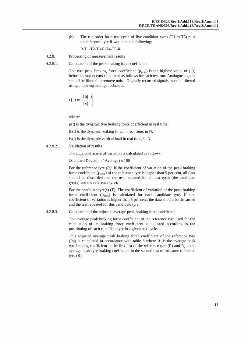
4.2.8.1. Calculation of the peak braking force coefficient
The tyre peak braking force coefficient (µpeak) is the highest value of µ(t)
before lockup occurs calculated as follows for each test run. Analogue signals
should be filtered to remove noise. Digitally recorded signals must be filtered
using a moving average technique.
where:
µ(t) is the dynamic tyre braking force coefficient in real time;
fh(t) is the dynamic braking force in real time, in N;
fv(t) is the dynamic vertical load in real time, in N.
4.2.8.2. Validation of results
The µpeak coefficient of variation is calculated as follows:
(Standard Deviation / Average) x 100
For the reference tyre (R): If the coefficient of variation of the peak braking
force coefficient (µpeak) of the reference tyre is higher than 5 per cent, all data
should be discarded and the test repeated for all test tyres (the candidate
tyre(s) and the reference tyre).
For the candidate tyre(s) (T): The coefficient of variation of the peak braking
force coefficient (µpeak) is calculated for each candidate tyre. If one
coefficient of variation is higher than 5 per cent, the data should be discarded
and the test repeated for this candidate tyre.
4.2.8.3. Calculation of the adjusted average peak braking force coefficient
The average peak braking force coefficient of the reference tyre used for the
calculation of its braking force coefficient is adjusted according to the
positioning of each candidate tyre in a given test cycle.
This adjusted average peak braking force coefficient of the reference tyre
(Ra) is calculated in accordance with table 3 where R1 is the average peak
tyre braking coefficient in the first test of the reference tyre (R) and R2 is the
average peak tyre braking coefficient in the second test of the same reference
tyre (R).
) (
) ( ) (
t fv
v
t fh
h
t

E/ECE/324/Rev.2/Add.116/Rev.2/Amend.1
E/ECE/TRANS/505/Rev.2/Add.116/Rev.2/Amend.1
16
Table 3
Number of candidate tyre(s) within one
test cycle
Candidate tyre Ra
1
(R1-T1-R2)
T1 Ra = 1/2 (R1 + R2)
2
(R1-T1-T2-R2)
T1 Ra = 2/3 R1 + 1/3 R2
T2 Ra = 1/3 R1 + 2/3 R2
3
(R1-T1-T2-T3-R2)
T1 Ra = 3/4 R1 + 1/4 R2
T2 Ra = 1/2 (R1 +R2)
T3 Ra = 1/4 R1 + 3/4 R2
4.2.8.4 Calculation of the average peak braking coefficient (µpeak,ave)
The average value of the peak braking coefficients (µpeak,ave) is calculated according to
table 4 whereby Ta (a= 1, 2 or 3) is the average of the peak braking force coefficients
measured for one candidate tyre within one test cycle.
Table 4
Test tyre µpeak,ave
Reference tyre µpeak,ave(R)=Ra as per Table 3
Candidate tyre µpeak,ave(T) = Ta
4.2.8.5. Calculation of the wet grip index of the candidate tyre
The wet grip index of the candidate tyre (G(T)) is calculated as follows:
where:
t is the measured wet surface temperature in degree Celsius when the
candidate tyre (T) is tested
t0 is the wet surface reference temperature condition
t0 = 20 °C for normal tyres t0=10°C for snow tyres
µpeak,ave(R0) = 0.85 is the peak braking force coefficient for the reference tyre
in the reference conditions
a = -0.4232 and b = -8.297 for normal tyres, a = 0.7721 and b = 31.18 for
snow tyres" [a is expressed as (1/°C)]
-2
0 ,
, 0
,
, 10 ) (
) ( ) ( 125
) (
) ( ) (
R
R b t t a
R
T T G
ave peak
ave peak
ave peak
ave peak
1.0

E/ECE/324/Rev.2/Add.116/Rev.2/Amend.1
E/ECE/TRANS/505/Rev.2/Add.116/Rev.2/Amend.1
17
Annex 5 – Appendix
Test reports examples of wet grip index
Example 1: Test report of wet grip index using trailer method
Test report number: Test date:
Type of road surface: Texture depth (mm):
µ peak (SRTT14 E1136) : or BPN:
Speed (km/h): Water depth (mm):
No. 1 2 3 4 5 6 7 8 9 10
Size
Service description
Tyre identification
Rim
Pattern
Load (N)
Pressure (kPa)
µpeak 1
2
3
4
5
6
7
8
Average
Standard deviation σ
(σ/average)≤5 per cent
Ra, Adjusted
Wet grip index
Surface temp. (°C)
Ambient temp. (°C)
Remarks

E/ECE/324/Rev.2/Add.116/Rev.2/Amend.1
E/ECE/TRANS/505/Rev.2/Add.116/Rev.2/Amend.1
18
Example 2: Test report of wet grip index using passenger car method
Driver: Test date:
Track: Passenger car: Initial speed (km/h):
Texture depth (mm): Brand: Final speed (km/h):
BPN: Model:
Water depth (mm): Type
No. 1 2 3 4 5
Brand Uniroyal TYRE B TYRE C TYRE D Uniroyal
Pattern ASTM F 2493
SRTT16
PATTERN B PATTERN C PATTERN D ASTM F 2493
SRTT16
Size P225/60R16 SIZE B SIZE C SIZE D P225/60R16
Service description 97S LI/SS LI/SS LI/SS 97S
Tyre identification XXXXXXXXX YYYYYYYYY ZZZZZZZZZ NNNNNNNNN XXXXXXXXX
Rim
Front axle pressure (kPa)
Rear axle pressure (kPa)
Front axle load (kg)
Rear axle load (kg)
Wet surface temp (°C)
Ambient temp (°C)
Braking distance
(m)
Average deceleration
(m/s2)
Braking distance
(m)
Average deceleration
(m/s2)
Braking distance
(m)
Average deceleration
(m/s2)
Braking distance
(m)
Average deceleration
(m/s2)
Braking distance
(m)
Average deceleration
(m/s2)
Measurement 1
2
3
4
5
6
7
8
9
10
Average AD (m/s2)
Standard deviation (m/s2)
Validation of results
Coeff. of variation (per
cent) < 3 per cent
Adjusted average AD of
ref. tyre: Ra (m/s2)
BFC(R) reference tyre
(SRTT16)
BFC(T) candidate tyre
Wet grip index (%)
"

E/ECE/324/Rev.2/Add.116/Rev.2/Amend.1
E/ECE/TRANS/505/Rev.2/Add.116/Rev.2/Amend.1
19
Annex 6,
Paragraph 3.5., amend to read:
"3.5. Duration and speed.
When the deceleration method is selected, the following requirements apply:
(a) The deceleration j shall be determined in exact dω/dt or approximate
Δω/Δt form, where ω is angular velocity, t – time;
(b) For duration Δt, the time increments shall not exceed 0.5 s;
(c) Any variation of the test drum speed shall not exceed 1 km/h within
one time increment."
Paragraph 4.6.2., amend to read:
"4.6.2. Deceleration method
The deceleration method follows the procedure below:
(a) Remove the tyre from the test surface;
(b) Record the deceleration of the test drum Do/ t and that of the
unloaded tyre T0/ t3
or record the deceleration of the test drum jD0
and that of the unloaded tyre jT0 in exact or approximate form in
accordance with paragraph 3.5."
Paragraph 5.1.5., amend to read:
"5.1.5. Deceleration method
Calculate the parasitic losses Fpl, in newton.
Where:
ID is the test drum inertia in rotation, in kilogram meter squared,
R is the test drum surface radius, in meter,
D0 is the test drum angular speed, without tyre, in radians per second,
t0 is the time increment chosen for the measurement of the parasitic losses without tyre, in second,
IT is the spindle, tyre and wheel inertia in rotation, in kilogram meter squared,
R is the tyre rolling radius, in metre,
T0 is the tyre angular speed, unloaded tyre, in radian per second.
or
T0r
TD0
Dpl j
R
Ij
R
IF
0
0
0
0
t R
I
t R
I F
T
r
T D D pl

E/ECE/324/Rev.2/Add.116/Rev.2/Amend.1
E/ECE/TRANS/505/Rev.2/Add.116/Rev.2/Amend.1
20
Where:
ID is the test drum inertia in rotation, in kilogram meter squared,
R is the test drum surface radius, in meter,
jD0 is the deceleration of the test drum, without tyre, in radians per second squared,
IT is the spindle, tyre and wheel inertia in rotation, in kilogram meter squared,
Rr is the tyre rolling radius, in metre,
jT0 is the deceleration of unloaded tyre, in radians per second squared."
Paragraph 5.2.5., amend to read:
"5.2.5. Deceleration method
The rolling resistance Fr, in newton, is calculated using the
equation: plV
V
2r
T
V
VD Ft
ω
R
RI
t
ω
R
IFr
Where:
ID is the test drum inertia in rotation, in kilogram metre squared,
R is the test drum surface radius, in meter,
Fpl represents the parasitic losses as calculated in paragraph 5.1.5.,
tv is the time increment chosen for measurement, in second,
Δv is the test drum angular speed increment, without tyre, in
radian per second,
IT is the spindle, tyre and wheel inertia in rotation, in kilogram
metre squared,
Rr is the tyre rolling radius, in metre,
Fr is the rolling resistance, in newton.
E/ECE/324/Rev.2/Add.116/Rev.2/Amend.1
E/ECE/TRANS/505/Rev.2/Add.116/Rev.2/Amend.1
21
or
plV2r
TV
D FjR
RIj
R
IFr
Where:
ID is the test drum inertia in rotation, in kilogram metre squared,
R is the test drum surface radius, in meter,
Fpl represents the parasitic losses as calculated in paragraph 5.1.5.,
jV is the deceleration of the test drum, in radians per second
squared,
IT is the spindle, tyre and wheel inertia in rotation, in kilogram
metre squared,
Rr is the tyre rolling radius, in metre,
Fr is the rolling resistance, in newton."
Annex 6, Appendix 1
Paragraph 4., amend to read:
"4. Control accuracy
…
(d) time: +/- 0.5 ms
…"
Annex 7,
Insert a new paragraph 1.4., to read:
"1.4. "Acceleration test" means a series of specified number of traction controlled
acceleration test runs of the same tyre repeated within a short timeframe."
Paragraph 3.1.2., amend to read:
"3.1.2. Vehicle
The test shall be conducted with a standard production vehicle in good
running order and equipped with an ABS system.
The vehicle used shall be such that the loads on each wheel are appropriate to
the tyres being tested. Several different tyre sizes can be tested on the same
vehicle."
Paragraph 3.1.3., amend to read:
"3.1.3. Tyres
The tyres should be "broken-in" prior to testing to remove spew, compound
nodules or flashes resulting from moulding process. The tyre surface in
contact with snow shall be cleaned before performing a test.
Tyres shall be conditioned at the outdoor ambient temperature at least two
hours before their mounting for tests. Tyre pressures shall then be adjusted to
the values specified for the test.

E/ECE/324/Rev.2/Add.116/Rev.2/Amend.1
E/ECE/TRANS/505/Rev.2/Add.116/Rev.2/Amend.1
22
In case a vehicle cannot accommodate both the reference and candidate tyres,
a third tyre ("control" tyre) may be used as an intermediate. First test control
vs. reference on another vehicle, then test candidate vs. control on the
vehicle."
Insert new paragraphs 3.4.3. to 4.10., to read:
"3.4.3. In the case where the candidate tyres cannot be fitted to the same vehicle as
the SRTT, for example, due to tyre size, inability to achieve required loading
and so on, comparison shall be made using intermediate tyres, hereinafter
referred to as "control tyres", and two different vehicles. One vehicle shall be
capable of being fitted with the SRTT and the control tyre and the other
vehicle shall be capable of being fitted with the control tyre and the
candidate tyre.
3.4.3.1. The snow grip index of the control tyre relative to the SRTT (SG1) and of
the candidate tyre relative to the control tyre (SG2) shall be established using
the procedure in paragraphs 3.1. to 3.4.2.
The snow grip index of the candidate tyre relative to the SRTT shall be the
product of the two resulting snow grip indices that is SG1 x SG2.
3.4.3.2. The ambient conditions shall be comparable. All tests shall be completed
within the same day.
3.4.3.3. The same set of control tyres shall be used for comparison with the SRTT
and with the candidate tyre and shall be fitted in the same wheel positions.
3.4.3.4. Control tyres that have been used for testing shall subsequently be stored
under the same conditions as required for the SRTT.
3.4.3.5. The SRTT and control tyres shall be discarded if there is irregular wear or
damage or when the performance appears to have been deteriorated.
4. Acceleration method for Class C3 tyres
4.1. According to the definition of C3 tyres reported into paragraph 2.4.3., the
additional classification for the purpose of this test method only applies:
(a) C3 Narrow (C3N), when the C3 tyre Nominal Section Width is lower
than 285 mm
(b) C3Wide (C3W), when the C3 tyre Nominal Section Width is greater
or equal to 285 mm
4.2. Methods for measuring Snow Grip Index
Snow performance is based on a test method by which the average
acceleration in an acceleration test, of a candidate tyre is compared to that of
a standard reference tyre.
The relative performance shall be indicated by a Snow Grip Index (SG).
When tested in accordance with the acceleration test in paragraph 4.7., the
average acceleration of a candidate snow tyre shall be at least 1.25 compared
to one of the two equivalent SRTTs – ASTM F 2870 and ASTM F 2871.
4.3. Measuring equipment
4.3.1. A sensor suitable for measuring speed and distance covered on snow/ice
surface between two speeds must be used.

E/ECE/324/Rev.2/Add.116/Rev.2/Amend.1
E/ECE/TRANS/505/Rev.2/Add.116/Rev.2/Amend.1
23
To measure vehicle speed, a fifth wheel or non-contact speed-measuring
system (including radar, GPS …) shall be used.
4.3.2. The following tolerances shall be respected:
(a) For speed measurements : ±1 per cent (km/h) or 0.5 km/h whichever
is greater.
(b) For distance measurements: ±1 x 10⁻¹
m
4.3.3. A display of the measured speed or the difference between the measured
speed and the reference speed for the test is recommended inside the vehicle
so that the driver can adjust the speed of the vehicle.
4.3.4. For Acceleration test covered in paragraph 4.7., a display of the slip ratio of
the driven tyres is recommended inside the vehicle and shall be used in the
particular case of paragraph 4.7.2.1.1.
The slip ratio is calculated by
100SpeedVehicle
SpeedVehicleSpeedWheel%RatioSlip
(a) Vehicle speed is measured as defined in 4.3.1. (m/s)
(b) Wheel speed is calculated on a tyre of the driven axle by measuring
its angular velocity and its loaded diameter
speedangulardiameterloadedπSpeedWheel
Where, π = 3.1416 (m/360deg), the loaded diameter (m) and the angular
speed (revolution per second = 360 deg/sec).
4.3.5. A data acquisition system can be used for storing the measurements.
4.4. General conditions
4.4.1. Test course
The test shall be done on a flat test surface of sufficient length and width,
with a maximum 2 per cent gradient, covered with packed snow.
4.4.1.1 The snow surface shall be composed of a hard packed snow base at least
3 cm thick and a surface layer of medium packed and prepared snow about
2 cm thick.
4.4.1.2. The snow compaction index measured with a CTI penetrometer shall be
between 80 and 90. Refer to the appendix of ASTM F1805 for additional
details on measuring method.
4.4.1.3. The air temperature, measured about one meter above the ground, shall be
between -2 °C and -15 °C; the snow temperature, measured at a depth of
about one centimetre, shall be between -4 °C and -15 °C.
Air temperature shall not vary more than 10 deg C during the test.
4.5. Tyres preparation and break-in
4.5.1. Fit the test tyres on rims as per ISO 4209-1 using conventional mounting
methods. Ensure proper bead seating by the use of a suitable lubricant.
Excessive use of lubricant should be avoided to prevent slipping of the tyre
on the wheel rim.

E/ECE/324/Rev.2/Add.116/Rev.2/Amend.1
E/ECE/TRANS/505/Rev.2/Add.116/Rev.2/Amend.1
24
4.5.2. The tyres should be "broken-in" prior to testing to remove spew, compound
nodules or flashes resulting from moulding process.
4.5.3. Tyres shall be conditioned at the outdoor ambient temperature at least two
hours before their mounting for tests.
They should be placed such that they all have the same ambient temperature
prior to testing and be shielded from the sun to avoid excessive heating by
solar radiation.
The tyre surface in contact with snow shall be cleaned before performing a
test.
Tyre pressures shall then be adjusted to the values specified for the test.
4.6. Testing sequence
If only one candidate tyre is to be evaluated, the order of testing shall be:
R1, T, R2
where:
R1 is the initial test of the SRTT, R2 is the repeat test of the SRTT and T is
the test of the candidate tyre to be evaluated.
A maximum of 3 candidate tyres may be tested before repeating the SRTT
test, for example: R1, T1, T2, T3, R2.
Recommendations are that the zones where acceleration is fully applied shall
not overlap without reworking and when a new set of tyres is tested;
The runs are performed after shifting the vehicle trajectory in order not to
accelerate on the tracks of the previous tyre; when it is no longer possible not
to overlap full acceleration zones, the test course should be re-groomed.
4.7. Acceleration on Snow Test Procedure for Snow Grip Index of Class C3N and
C3W
4.7.1. Principle
The test method covers a procedure for measuring the Snow Grip
performance of commercial vehicle tyres during acceleration, using a
commercial vehicle having a Traction Control System (TCS, ASR, etc.).
Starting with a defined initial speed, the full throttle is applied to activate the
Traction Control system, the Average acceleration is calculated between two
defined speeds.
4.7.2. Vehicle
4.7.2.1 The test shall be conducted with a 2 axles standard model commercial vehicle
in good running conditions equipped with:
(a) Low rear axle weight and enough powerful engine to ensure the
average percentage of slip during the test as required in points 4.7.5.1.
and 4.7.5.2.1. below;
(b) A manual gearbox (automatic gearbox with manual shift allowed)
having a gear ratio covering a 19 km/h range between 4 and 30 km/h;
(c) Blocking differential on driven axle is recommended as increasing
repeatability;

E/ECE/324/Rev.2/Add.116/Rev.2/Amend.1
E/ECE/TRANS/505/Rev.2/Add.116/Rev.2/Amend.1
25
(d) A standard commercial system controlling/limiting the slip of the
driving axle when accelerating (called Traction Control, ASR, TCS,
etc.).
4.7.2.1.1. In the particular case where it is not possible to find a standard commercial
vehicle equipped with a traction control system, a vehicle without Traction
Control/ASR/TCS is allowed with a mandatory display of the percentage slip
as stated in 4.3.4. and a mandatory blocking differential on the driven axle to
put in practice the operating procedure 4.7.5.2.1.
4.7.2.2. The permitted modifications are:
(a) Those allowing to increase the number of tyre sizes capable to be
mounted on the vehicle;
(b) Those permitting to install an automatic activation of the acceleration
and the measurements.
Any other modification of the acceleration system is prohibited.
4.7.3. Vehicle fitting
The rear driven axle may be indifferently fitted with 2 or 4 test tyres if
respecting the loading by tyre.
The front steer non driven axle is equipped with 2 tyres having a size suitable
for the axle load. These 2 front tyres could be maintained along the test.
4.7.4. Load and inflation pressure
4.7.4.1. The static load on each rear driven test tyres must be between 20 per cent and
55 per cent of the tested tyre load capacity written on the sidewall.
The vehicle front steer total static axle load should be between 60 per cent
and 160 per cent of the driven rear total axle load.
The static tyre load on the same driven axle should not differ by more than
10 per cent.
4.7.4.2. The driven tyres inflation pressure shall be 70 per cent of the one written on
the sidewall.
The steer tyres are inflated at nominal sidewall pressure
4.7.5. Testing Runs
4.7.5.1. Mount first the set of reference tyres on the vehicle and when on the testing
area.
Drive the vehicle at an initial constant speed between 4 km/h and 11 km/h
and the gear ratio capable of covering the speed range of 19 km/h.
Recommended Gear ratio selected is 3rd or 4th shall give minimum 13 per
cent average slip ratio in the measured range of speed.
4.7.5.2. In case of Traction Control system equipped vehicles (already switched "on"
before the run) apply full throttle until the vehicle has reached the final speed.
Final speed = Initial speed + 15 km/h
No rearward restraining force shall be applied to the test vehicle.
4.7.5.2.1. In the particular case of paragraph 4.7.2.1.1. where it is not possible to find a
standard commercial vehicle having the Traction Control system, the driver

E/ECE/324/Rev.2/Add.116/Rev.2/Amend.1
E/ECE/TRANS/505/Rev.2/Add.116/Rev.2/Amend.1
26
maintains manually the averaged slip ratio range of 20 per cent ± 10 per cent
(Controlled Slip procedure in place of the Full Slip) in the same range of
speeds. All the tyres and runs in the test session are performed with
Controlled Slip procedure.
4.7.5.3. Measure the distance and the time between the initial speed and the final
speed.
4.7.5.4. For every candidate tyre and the standard reference tyre, the acceleration test
runs shall be repeated a minimum of 6 times and the coefficients of variation
(standard deviation/average*100) calculated for minimum 6 valid runs on the
distance and the time should be lower than or equal to 6 per cent.
4.7.5.5 In case of Traction Control System equipped vehicle, the Average Slip ratio
shall be in the range from 13 per cent to 40 per cent (calculated as per in
paragraph 4.3.4.)
4.7.5.6. Apply testing sequence as defined in paragraph 4.6.
4.8. Processing of measurement results
4.8.1. Calculation of the Average Acceleration AA
Each time the measurement is repeated, the average acceleration AA (m ∙ s-2)
is calculated by
D2
SSAA
2i
2f
Where D (m) is the distance covered between the initial speed Si (m.s-1
) and
the final speed Sf (m.s-1
).
4.8.2. Validation of results
For the candidate tyres:
The coefficients of variation of the Average Acceleration is calculated for all
the candidate tyres. If one coefficient of variation is greater than 6 per cent,
discard the data for this candidate tyre and repeat the test.
100average
stdevvariationoftcoefficien
For the reference tyre:
If the coefficient of variation of the average Acceleration "AA" for each
group of min 6 runs of the reference tyre is higher than 6 per cent, discard all
data and repeat the test for all tyres (the candidate tyres and the reference
tyre).
In addition and in order to take in account possible test evolution, the
coefficient of validation is calculated on the basis of the average values of
any two consecutive groups of min 6 runs of the reference tyre. If the
coefficient of validation is greater than 6 per cent, discard the data for all the
candidate tyres and repeat the test.
100Average1
Average1Average2validationoftcoefficien

E/ECE/324/Rev.2/Add.116/Rev.2/Amend.1
E/ECE/TRANS/505/Rev.2/Add.116/Rev.2/Amend.1
27
4.8.3. Calculation of the "average AA"
If R1 is the average of the "AA" values in the first test of the reference tyre,
R2 is the average of the "AA" values in the second test of the reference tyre,
the following operations are performed, according to Table 1:
Table 1
If the number of sets of
candidate tyres between two
successive runs of the
reference tyre is:
and the set of candidate tyres
to be qualified is:
then "Ra" is calculated by
applying the following:
1 R - T1 – R T1 Ra = 1/2 (R1 + R2)
2 R - T1 – T2 – R T1
T2
Ra = 2/3 R1 + 1/3
R2
Ra = 1/3 R1 + 2/3
R2
3 R - T1 – T2 - T3 – R T1
T2
T3
Ra = 3/4 R1 + 1/4
R2
Ra = 1/2 (R1 + R2)
Ra = 1/4 R1 + 3/4
R2
"Ta" (a = 1, 2, …) is the average of the AA values for a test of a candidate
tyre.
4.8.4 "AFC" Calculation (Acceleration Force Coefficient)
Also called AFC Acceleration Force Coefficient
Calculation on of AFC(Ta) and AFC(Ra) as defined in table 2 :
Table 2
The Acceleration Force
Coefficient "AFC" is:
Reference tyre AFC(R) = g
Ra
Candidate tyre AFC(T) = g
Ta
Ra and Ta are in m/s²
"g"= gravity acceleration (rounded to 9.81 m/s2)
4.8.5. Calculation of the relative Snow Grip Index of the tyre
The Snow grip index represents the relative performance of the candidate tyre
compared to the reference tyre.
AFC(R)
AFC(T)IndexGripSnow

E/ECE/324/Rev.2/Add.116/Rev.2/Amend.1
E/ECE/TRANS/505/Rev.2/Add.116/Rev.2/Amend.1
28
4.8.6. Calculation of the Slip Ratio
The slip ratio can be calculated as the average of Slip ratio as mentioned in
paragraph 4.3.4. or by comparing the average distance referred to in
paragraph 4.7.5.3. of the min 6 runs to the distance of a run done without slip
(very low acceleration)
100distance slip No
distance slip Nodistance Average%RatioSlip
4.9. Snow grip performance comparison between a candidate tyre and a reference
tyre using a control tyre
4.9.1. Scope
When the candidate tyre size is significantly different from the reference tyre
a direct comparison on the same vehicle may be not possible. This is an
approach using an intermediate tyre, hereinafter called the control tyre.
4.9.2. Principle of the approach
The principle lies upon the use of a control tyre and 2 different vehicles for
the assessment of a candidate tyre in comparison with a reference tyre.
One vehicle can fit the reference tyre and the control tyre, the other the
control tyre and the candidate tyre. All conditions are in conformity with
paragraph 4.7.
The first assessment is a comparison between the control tyre and the
reference tyre. The result (Snow Grip Index 1) is the relative efficiency of the
control tyre compared to the reference tyre.
The second assessment is a comparison between the candidate tyre and the
control tyre. The result (Snow grip index 2) is the relative efficiency of the
candidate tyre compared to the control tyre.
The second assessment is done on the same track as the first one. The air
temperature must be in the range of +/- 5 deg C of the temperature of the first
assessment. The control tyre set is the same set as the set used for the first
assessment.
The Snow Grip performance Index of the candidate tyre compared to the
reference tyre is deduced by multiplying the relative efficiencies calculated
above:
SG2SG1IndexGripSnow
4.9.3. Selection of a set of tyres as a control tyre set
A control tyre set is a group of identical tyres made in the same factory
during one week period.
4.10. Storage and preservation
Before the first assessment (control tyre / reference tyre), normal storage
conditions can be used. It is necessary that all the tyres of a control tyre set
have been stored in the same conditions.
As soon as the control tyre set has been assessed in comparison with the
reference tyre, specific storage conditions shall be applied for Control tyres
replacement.

E/ECE/324/Rev.2/Add.116/Rev.2/Amend.1
E/ECE/TRANS/505/Rev.2/Add.116/Rev.2/Amend.1
29
When irregular wear or damage results from tests, or when wear influences
the test results, the use of the tyre shall be discontinued."
Annex 7,
Appendix 2,
Paragraph 4.3., amend the table to read :
"
SRTT (1st test) Candidate Candidate SRTT (2nd test)
Tyre dimensions
Test rim width code
Tyre loads F/R (kg)
Load index F/R (per cent)
Tyre pressure F/R (kPa)
"
Annex 7, insert a new Appendix 3, to read:
"Annex 7 - Appendix 3
Test reports and test data for C3 tyres
Part 1 - Report
1. Type Approval Authority or Technical Service: ..........................................................
2. Name and address of applicant: ....................................................................................
3. Test report No.: ............................................................................................................
4. Manufacturer and brand name or trade description: ....................................................
5. Tyre class: ....................................................................................................................
6. Category of use: ...........................................................................................................
7. Snow index relative to SRTT according to paragraph 8.5.
7.1. Test procedure and SRTT used ....................................................................................
8. Comments (if any): ......................................................................................................
9. Date: .............................................................................................................................
10. Signature: .....................................................................................................................
Part 2 - Test data
1. Date of test: ..................................................................................................................
2. Location of test track: ..................................................................................................
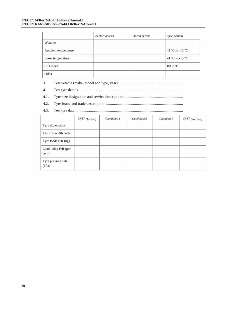
2.1. Test track characteristics:
E/ECE/324/Rev.2/Add.116/Rev.2/Amend.1
E/ECE/TRANS/505/Rev.2/Add.116/Rev.2/Amend.1
30
At start of tests At end of tests specification
Weather
Ambient temperature -2 °C to -15 °C
Snow temperature -4 °C to -15 °C
CTI index 80 to 90
Other
3. Test vehicle (make, model and type, year): ..................................................................
4. Test tyre details ............................................................................................................
4.1. Tyre size designation and service description: .............................................................
4.2. Tyre brand and trade description: ................................................................................
4.3. Test tyre data: ...............................................................................................................
SRTT (1st test) Candidate 1 Candidate 2 Candidate 3 SRTT (2nd test)
Tyre dimensions
Test rim width code
Tyre loads F/R (kg)
Load index F/R (per
cent)
Tyre pressure F/R
(kPa)

E/ECE/324/Rev.2/Add.116/Rev.2/Amend.1
E/ECE/TRANS/505/Rev.2/Add.116/Rev.2/Amend.1
31
5. Test results: average accelerations (m/s²)
Run number Specification SRTT (1st test) Candidate 1 Candidate 2 Candidate 3 SRTT (2nd test)
1
2
3
4
5
6
Mean
Std-deviation
Slip ratio (per
cent)
CV (per cent) < 6 per cent
Validation SRTT (SRTT) < 5 per
cent
SRTT average
Snow index
1,00
"