agp agp 4x/8x ( ) agp 4x/8x(1.5v) · declaration of conformity we, manufacturer/importer (full...
TRANSCRIPT

AGPAGP 4X/8X ( )AGP 4X/8X(1.5V)
AGP 2X VIA® KT600AGP 2X(3.3V) AGP 2X (3.3V)
AGP 4X/8X(1.5V)
Diamond Vipper V770 2X/4X Jumper 2X 4X
2X(3.3V) GA-7VT600-P(-L)Jumper 4X (1.5V)
SiS 305 Power Color ATi Rage128 Pro 2X/4X
2X(3.3V) GA-7VT600-P(-L)
AG32S(G) ATiRage 128 Pro AGP4X(1.5V)
AGP 4X/8X
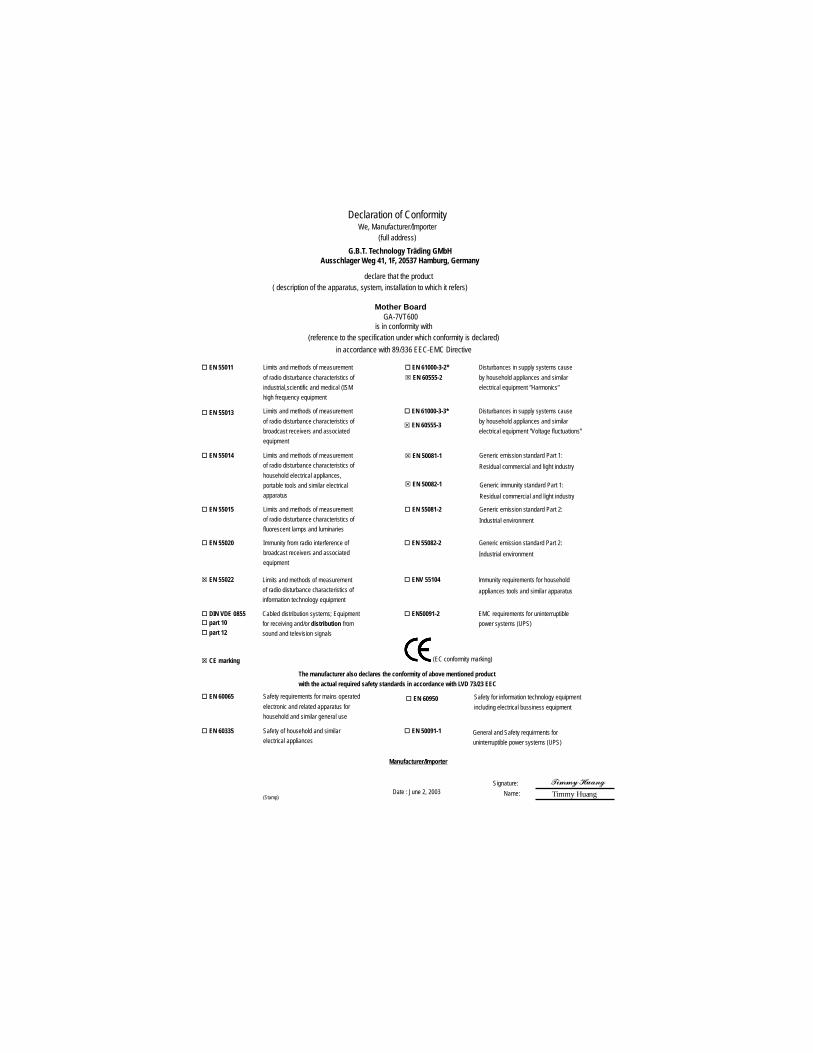
Declaration of ConformityWe, Manufacturer/Importer
(full address)
G.B.T. Technology Träding GMbHAusschlager Weg 41, 1F, 20537 Hamburg, Germany
declare that the product( description of the apparatus, system, installation to which it refers)
Mother BoardGA-7VT600
is in conformity with(reference to the specification under which conformity is declared)
in accordance with 89/336 EEC-EMC Directive
� EN 55011 Limits and methods of measurement
of radio disturbance characteristics of
industrial,scientific and medical (ISM
high frequency equipment
� EN 61000-3-2*
� EN 60555-2
Disturbances in supply systems cause
by household appliances and similar
electrical equipment “Harmonics”
� EN 55013 Limits and methods of measurement
of radio disturbance characteristics of
broadcast receivers and associated
equipment
� EN 61000-3-3* Disturbances in supply systems cause
by household appliances and similar
electrical equipment “Voltage fluctuations”
� EN 55014 Limits and methods of measurement
of radio disturbance characteristics of
household electrical appliances,
portable tools and similar electrical
apparatus
� EN 50081-1 Generic emission standard Part 1:
Residual commercial and light industry
� EN 50082-1 Generic immunity standard Part 1:
Residual commercial and light industry
� EN 55015 Limits and methods of measurement
of radio disturbance characteristics of
fluorescent lamps and luminaries
Generic emission standard Part 2:
Industrial environment
� EN 55081-2
Immunity from radio interference of
broadcast receivers and associated
equipment
Generic emission standard Part 2:
Industrial environment
� EN 55082-2
� EN 55022 Limits and methods of measurement
of radio disturbance characteristics of
information technology equipment
lmmunity requirements for household
appliances tools and similar apparatus
� ENV 55104
Cabled distribution systems; Equipment
for receiving and/or distribution from
sound and television signals
EMC requirements for uninterruptible
power systems (UPS)
� EN50091-2
� EN 55020
� DIN VDE 0855� part 10
� part 12
(EC conformity marking)� CE marking
The manufacturer also declares the conformity of above mentioned product
with the actual required safety standards in accordance with LVD 73/23 EEC
Safety requirements for mains operated
electronic and related apparatus for
household and similar general use
� EN 60950� EN 60065
Safety of household and similar
electrical appliances
� EN 60335
Manufacturer/Importer
Signature:
Name:(Stamp)
Date : June 2, 2003
� EN 60555-3
���������
Timmy Huang
� EN 50091-1
Safety for information technology equipment
including electrical bussiness equipment
General and Safety requirments for
uninterruptible power systems (UPS)

FCC Part 15, Subpart B, Section 15.107(a) and Section 15.109
(a),Class B Digital Device
DECLARATION OF CONFORMITYPer FCC Part 2 Section 2.1077(a)
Responsible Party Name:
Address:
Phone/Fax No:
hereby declares that the product
Product Name:
Conforms to the following specifications:
This device complies with part 15 of the FCC Rules. Operation is
subject to the following two conditions: (1) This device may not
cause harmful and (2) this device must accept any inference received,
including that may cause undesired operation.
Representative Person’s Name:
Signature: �������
Supplementary Information:
Model Number:
17358 Railroad Street
City of Industry, CA 91748
G.B.T. INC. (U.S.A.)
(818) 854-9338/ (818) 854-9339
Motherboard
GA-7VT600
Date:
ERIC LU
June 2 ,2003
GA-7VT600-P(-L)
AMD Socket A
AMD AthlonTM / AthlonTM XP/ DuronTM Socket A
Rev. 1001
12MC-7VT600P-1001
- 2 -GA-7VT600-P(-L)
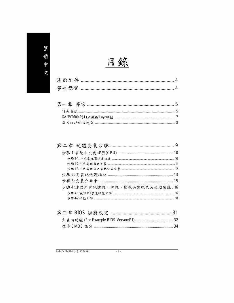
............................................................................ 4
............................................................................ 4
....................................................................... 5.............................................................................................................. 5
GA-7VT600-P(-L) Layout ..................................................................... 7
........................................................................................... 8
.................................................... 91: (CPU) .......................................................... 10
1-1: ............................................................................... 10
1-2: ...................................................................................... 11
1-3: ................................................................... 12
2 : .................................................................... 13
3 : .............................................................................. 15
4 : . 164-1: I/O .............................................................................. 16
4-2: ...................................................................................................... 18
BIOS .................................................. 31 (For Example BIOS Verson:F1)........................................ 32
CMOS ................................................................................... 34
- 3 -
BIOS ............................................................................ 37
....................................................................................... 39
....................................................................................... 43
PCI ................................................................ 46
....................................................................................... 47
/ .................................................................................... 49
Fail-Safe ........................................................................... 51
Optimized ......................................................................... 52
(Supervisor)/ (User) ................................... 53
SETUP .......................................................... 54
SETUP ..................................................... 55
......................................... 57BIOS ............................................................................. 57
@ BIOSTM ........................................................................................ 61
Easy TuneTM 4 ................................................................................. 62
/ / ................................................ 63
Jack-Sensing ......................................................................... 69
Xpress Recovery .................................................................... 71
..................................................................... 75

- 4 -GA-7VT600-P(-L)
GA-7VT600-P(-L)
GA-7VT600-P(-L)
RAID
x2 / x 1
2 x 1
1.
2.
3. (CPU RAM)
4.
5. ATX
PCB
4 x 1
Audio combo Kit x1
IEEE1394 x 1
Serial ATA x 2
Serial ATA x 1
I/O
Motherboard Settings

- 5 -
.......
� ATX 30.5 x 20.0� AMD AthlonTM / AthlonTM XP / DuronTM (K7) Socket A
128K 256K/64K CPU, 200/266/333/400 MHz FSB
� 1.4 GHz� VIA KT600 Memory/AGP/PCI� VT8237� 3 184-pin DDR DIMM� PC2100/PC2700/PC3200 DDR DRAM� 3.0GB DDR� only 2.5V DDR DIMM
I/O � IT8705� 1 AGP , 8X/4X(1.5V) AGP3.0� 5 PCI 33MHz PCI2.2 compliant
IDE � 2 IDE bus master (ATA 66/100/133) IDE 4 ATAPI .� 1 (360K,720K,1.2M,1.44M
2.88M bytes)� 1 Normal/EPP/ECP� 2 (COM A & COM B)� 8 2.0/1.1 ( 4 )� CPU /� CPU /�
� CPU /� CPU� CODEC (RealTek ALC655)� Jack Sensing � Line Out : 2 � Line In : 2 ( )� Mic In : / ( )� SPDIF Out/SPDIF In� CD In / AUX_In
- 6 -GA-7VT600-P(-L)
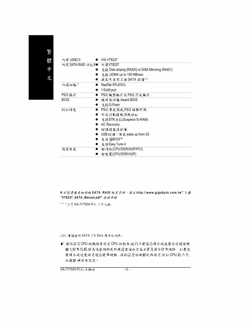
USB2.0 VIA VT8237SATA RAID # VT8237
Disk striping (RAID0) or DISK Mirroring (RAID1) UDMA up to 150 MB/sec
2 SATA ( )
* RealTek RTL8101L1 RJ45 port
PS/2 PS/2 PS/2BIOS Award BIOS
Q-FlashPS/2 ,PS/2
STR (Suspend-To-RAM)AC Recovery
USB wake up from S3@BIOSTM
Easy Tune 4(CPU/DDR/AGP/PCI)(CPU/DDR/AGP)
CPU CPU ,,
, , ;CPU, ,,
" * " GA-7VT600-P-L .
# SATA RAID ht tp : \ \www.g igaby te .com. tw""VT8237_SATA_Manual.pdf"
( ) SATA 1.5 Gb/s
- 7 -
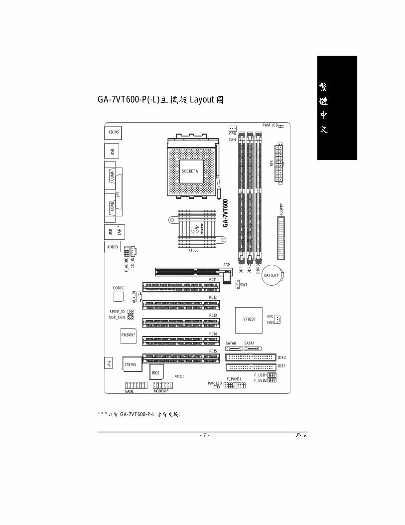
GA-7VT600-P(-L) Layout
" * " GA-7VT600-P-L .
GA-
7VT6
00
KB_MS
COM
ALP
T
IT8705
CODEC
BATTERY
BIOS
SYS
FANVT8237
KT600
SOCKET A
CPU
FAN
ATX
FLO
PPY
IDE1
PCI1
PCI2
PCI3
PCI4
DD
R1AGP
SW1
F_USB1
COM
B
CD
_IN
PCI5
DD
R2
DD
R3
F_AU
DIO
CIF_PANEL F_USB2
AUX_
IN
SUR_CENSPDIF_IO
PWR_LED
RAM_LED
GAME
AUDIO
USB
LAN
*
-P-L
IDE2
RTL8101L*
MODEM *
SATA0 SATA1
USB

- 8 -GA-7VT600-P(-L)
" * " GA-7VT600-P-L .
VIA
KT600
VIA
VT8237
CPUCLK+/- (100/133/166/200MHz)
System Bus100/133/166/200MHz
DDR RAM
HCLK+/- (100/133/166/200MHz)
AGPCLK66MHz
33 MHz14.318 MHz
48 MHz
AGP 4X/8X
AGPCLK
(66MHz)
5 PCI
PCICLK
(33MHz)
AC97
Lin
k
8 USB
Ports
ATA66/100/133
IDE Channels
CLK
GEN
HCLK+/- (100/133/166/200MHz)CPUCLK+/- (100/133/166/200MHz)AGPCLK (66MHz)
PCICLK (33MHz)USBCLK (48MHz)
14.318 MHz33 MHz
IT8705
24 MHz
33 MHz
Game Port
Floppy
LPT Port
PS/2 KB/Mouse
COM
Ports
AC97
CODEC
MIC
LIN
E-IN
LIN
E-O
UT
AMD-K7TM
BIOS
66M
Hz
V_Li
nk
V_Link (66MHz)
RTL8101L*
RJ45*
2 SATA
Ports

- 9 -
1 - Dip Switch (CK_RATIO) Switch (SW1)
2 - (CPU)
3 -
4 -
5 -
3
14
5
5
2
5
, !!
,
, ,
BIOS
- 10 -GA-7VT600-P(-L)
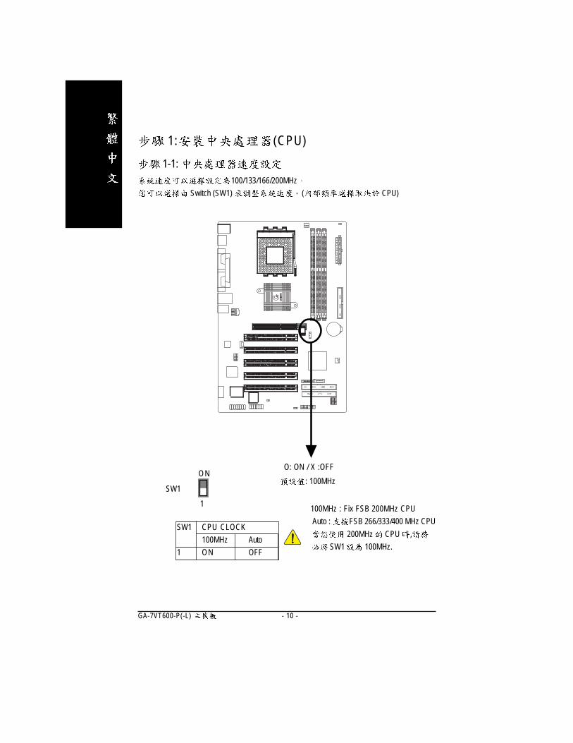
1: (CPU)
1-1: 100/133/166/200MHz
Switch (SW1) ( CPU)
O: ON / X :OFF
SW1 CPU CLOCK
100MHz Auto
1 ON OFF
SW1
1
ON: 100MHz
100MHz : Fix FSB 200MHz CPU
Auto : FSB 266/333/400 MHz CPU
200MHz CPU ,
SW1 100MHz.
- 11 -
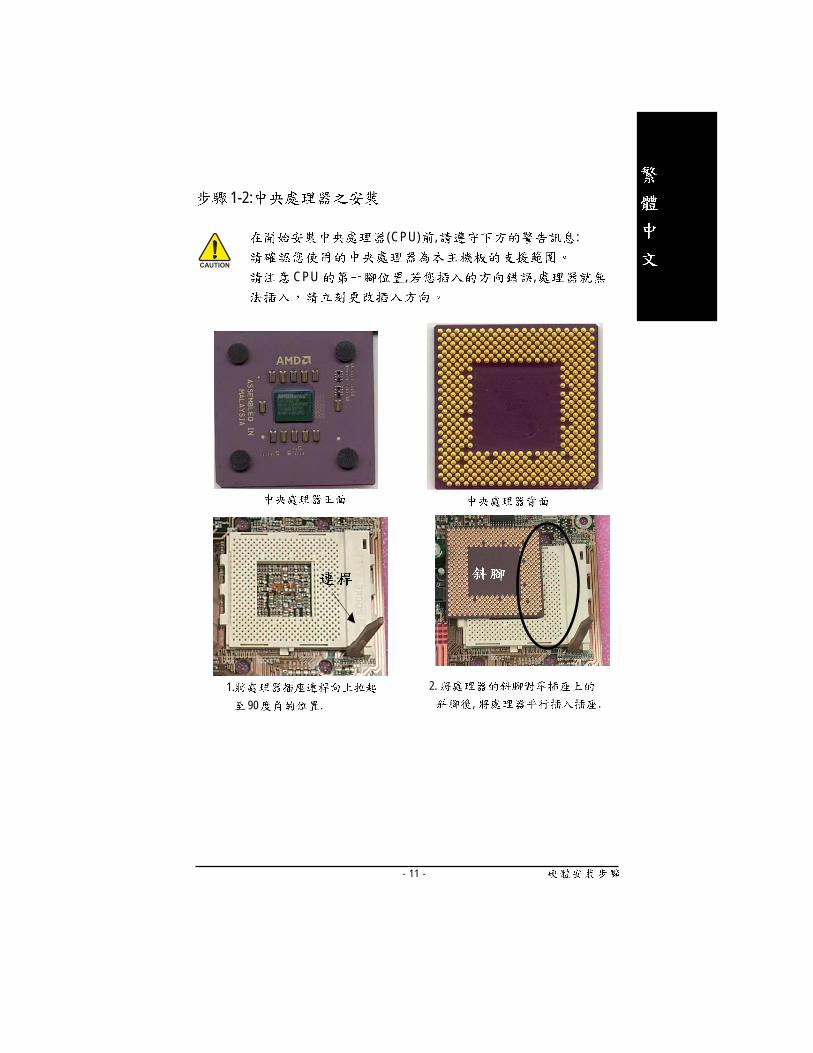
1-2:
1.
90 .
2.
, .
(CPU) , :
CPU , ,

- 12 -GA-7VT600-P(-L)
1-3:
3. CPU
, ;
.
2. AMD
4. CPU
CPU FAN
, .
1.
(CPU) ,
:
1. AMD
2.CPU
3. ,
CPU CPU FAN ,
( )
- 13 -
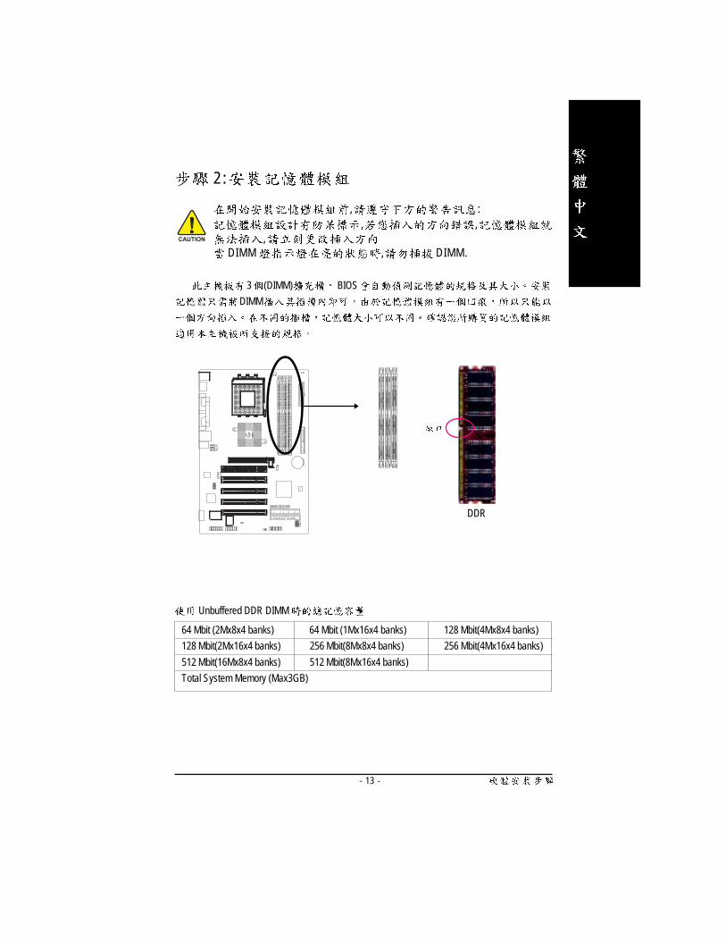
2 :
, :, ,
,DIMM , DIMM.
3 (DIMM) BIOS
DIMM
DDR
Unbuffered DDR DIMM
64 Mbit (2Mx8x4 banks) 64 Mbit (1Mx16x4 banks) 128 Mbit(4Mx8x4 banks)
128 Mbit(2Mx16x4 banks) 256 Mbit(8Mx8x4 banks) 256 Mbit(4Mx16x4 banks)
512 Mbit(16Mx8x4 banks) 512 Mbit(8Mx16x4 banks)
Total System Memory (Max3GB)
- 14 -GA-7VT600-P(-L)
DDR
DDR(Double Data Rate) PC SDRAM
SDRAM
DDR OEM
DDR SDRAM
SDRAM DDR SDRAM
DDR 3.2GB/s(DDR400)
DDR DRAM
PC
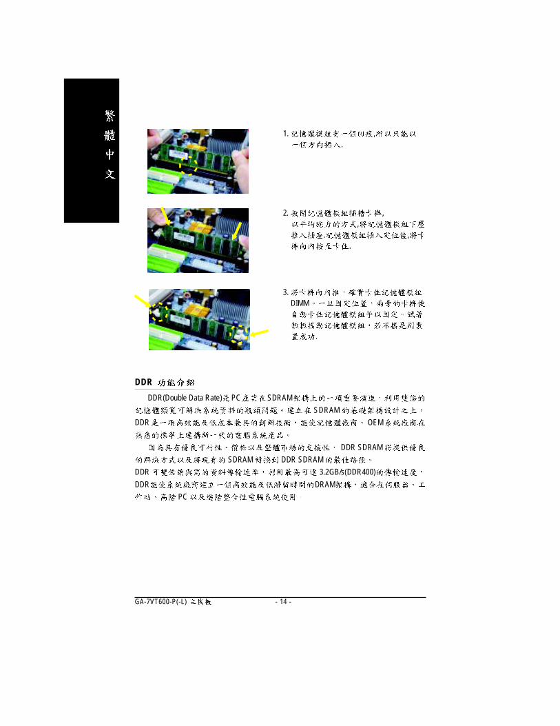
1. ,.
3. DIMM
.
2. ,,
. ,.
- 15 -
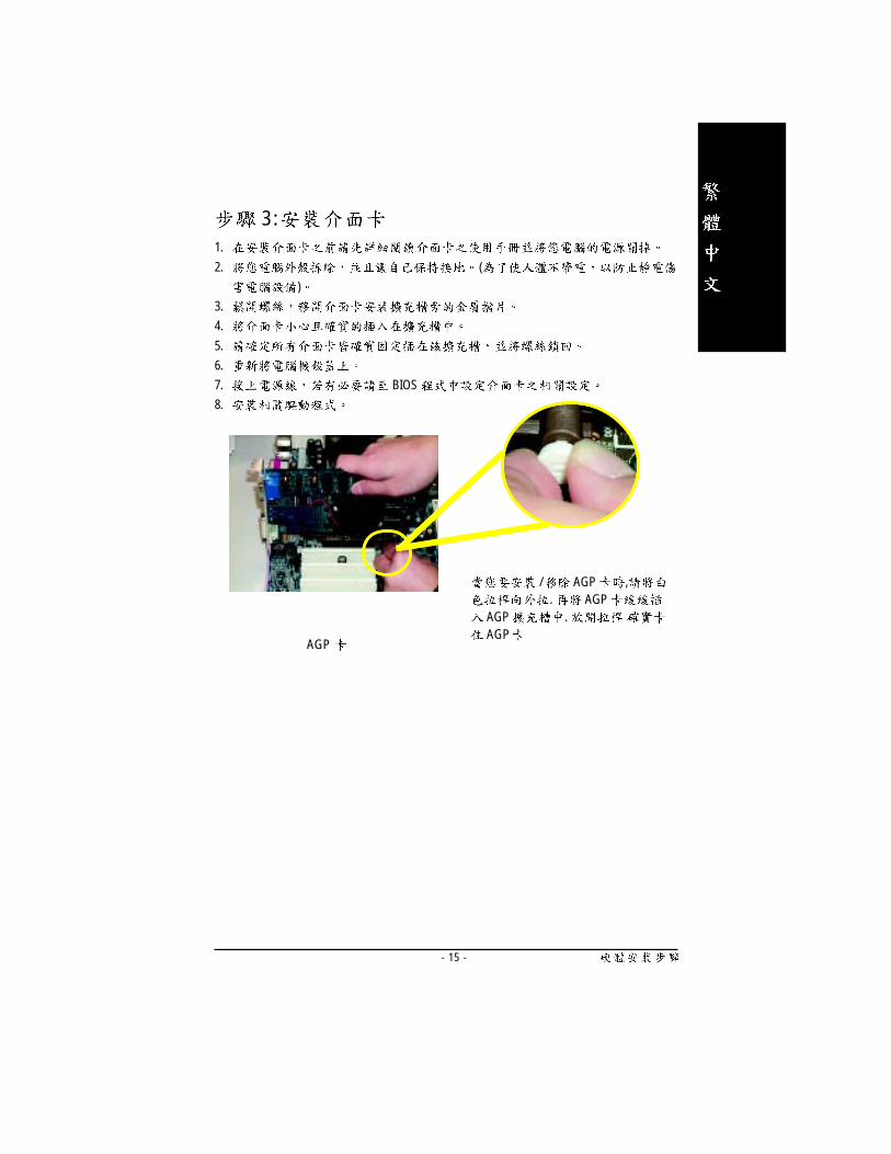
3 :1.
2. (
)
3.
4.
5.
6.
7. BIOS
8.
AGP
/ AGP ,. AGP
AGP . AGP

- 16 -GA-7VT600-P(-L)
� PS/2 PS/2
PS/2
(6 pin Female)
PS/2
(6 pin Female)
PS/2
PS/2
4
4-1 I/O
�
�
� �
�
USB USB
USB USB ZIP USB
USB
USB 3( 1)
� /� /
LAN*( )USB 2( 0)
USB 1( 1)
USB 0( 0)
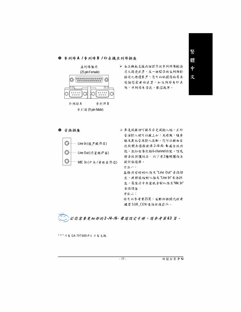
- 17 -
�
2-/4-/6-
6-channel
2
"Line Out"
"Line In"
"Mic In"
25
SUR_CEN
2 - / 4 - / 6 - 6 3
Line In ( )
MIC In ( / )
Line Out ( )
" * " GA-7VT600-P-L .
� A / B /
�
(25 pin Female)
A
(9 pin Male)
B
- 18 -GA-7VT600-P(-L)
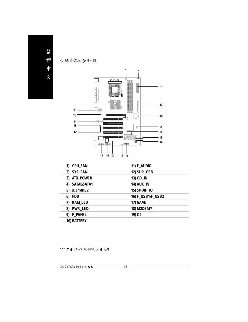
4-2:
" * " GA-7VT600-P-L .
17
15
12
1) CPU_FAN
2) SYS_FAN
3) ATX_POWER
4) SATA0/SATA1
5) IDE1/IDE2
6) FDD
7) RAM_LED
8) PWR_LED
9) F_PANEL
10) BATTERY
7
6
3
1
5
13
11
11) F_AUDIO
12) SUR_CEN
13) CD_IN
14) AUX_IN
15) SPDIF_IO
16) F_USB1/F_USB2
17) GAME
18) MODEM *
19) CI
2
16
14
8
10
91918
4

- 19 -
1) CPU_FAN (CPU )
CPU 600
2) SYS_FAN ( )A G P P C I
12 +12V3 Sense
12 +12V3 Sense
1
1

- 20 -GA-7VT600-P(-L)
3) ATX (ATX )AC ( 1 1 0/ 2 20 V ) ATX
ATX AC (110/220V).
1 3.3V2 3.3V34 VCC56 VCC78 Power Good9 5V SB(stand by +5V)10 +12V11 3.3V12 -12V1314 PS_ON(softOn/Off)15161718 -5V19 VCC20 VCC
20
1 11
10
4) SATA0 / SATA1 (Serial ATA )Ser ia l ATA 150MB Ser ia l ATA
SAT A R A I D h t tp : \ \w w w. g i g a b y t e. c o m. tw ""VT8237_SATA_Manual.pdf"
Pin No. Definition
1 GND
2 TXP
3 TXN
4 GND
5 RXN
6 RXP
7 GND
SATA0
7 1 71
SATA1
- 21 -
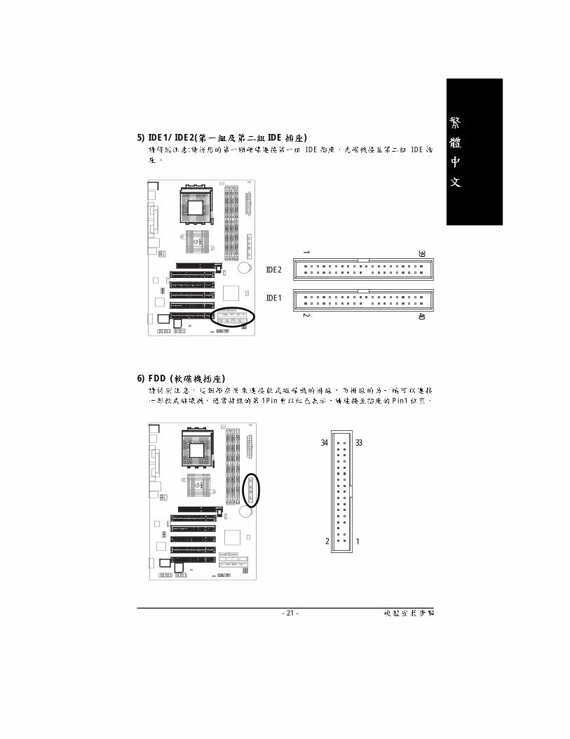
6) FDD ( )
1 P i n P i n 1
1
34
2
33
5) IDE1/ IDE2( IDE ): I DE I DE
IDE1
IDE22 40
1 39
- 22 -GA-7VT600-P(-L)
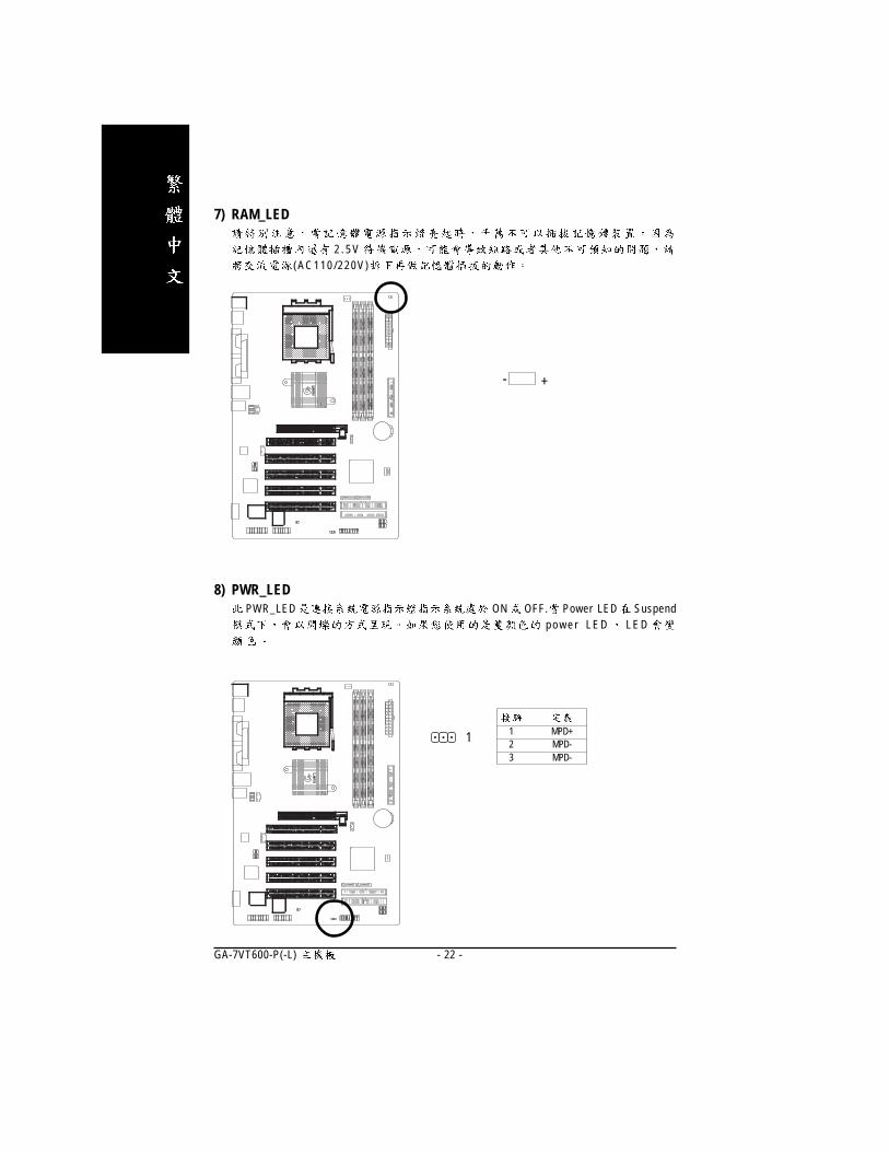
8) PWR_LEDPWR_LED ON OFF. Power LED Suspend
p o w e r L E D L E D
1 1 MPD+2 MPD-3 MPD-
7) RAM_LED
2 . 5 V(AC110 /220V)
+-

- 23 -
1
HD+
SPK-
19
HD-
SPK+
2021
1
Speaker
Connector
Soft Power
Connector
1
11
MSG+MSG-
Message LED/Power/
Sleep LED
PW-
PW+
IDE Hard Disk
Active LED
RES+
RES-
Reset Switch
NC
9) F_PANEL (2x10 pins connector)
.
HD (IDE Hard Disk Active LED) Pin 1: LED anode(+)( ) Pin 2: LED cathode(-)
��
SPK (Speaker Connector) Pin 1: VCC(+) +5v( ) Pin 2- Pin 3: NC
Pin 4: Data(-) RES (Reset Switch) Open: Normal Operation
( ) Close: Reset Hardware System
� �
PW (Soft Power Connector) Open: Normal Operation :( ) Close: Power On/Off : /
� �
MSG(Message LED/Power/ Pin 1: LED anode(+)Sleep LED) ( ) Pin 2: LED cathode(-)
��
- 24 -GA-7VT600-P(-L)
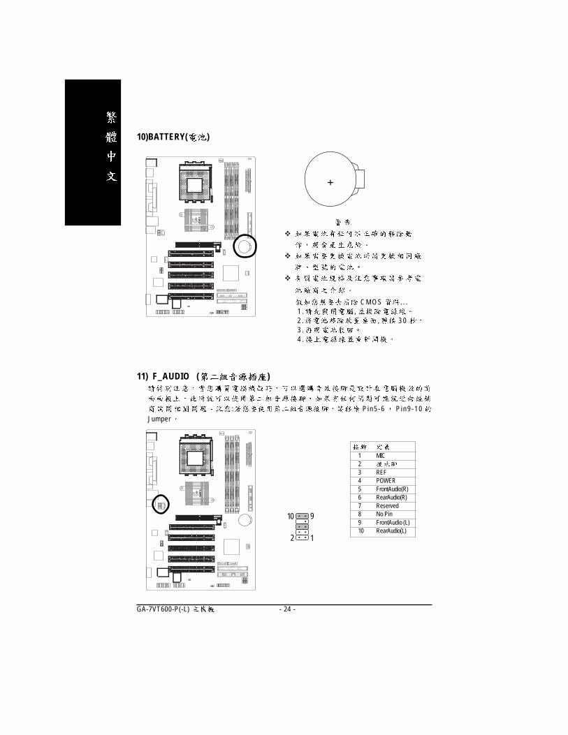
11) F_AUDIO ( )
: P i n 5 - 6 P i n 9 - 1 0Jumper
1 MIC23 REF4 POWER5 FrontAudio(R)6 RearAudio(R)7 Reserved8 No Pin9 FrontAudio (L)10 RearAudio(L)
1
10
2
9
+
10)BATTERY( )
�
�
�
C M O S . . .1 . ,2 . , 3 03 .4 .
- 25 -
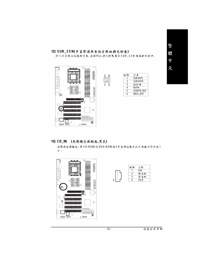
13) CD_IN ( , )
C D- R OM D VD- R OM C D
1 CD-L234 CD_R1
12) S U R _ C E N ( ), S U R _ C E N .
1 SUR OUTL2 SUR OUTR34 No Pin5 CENTER_OUT6 BASS_OUT
1
62
5
- 26 -GA-7VT600-P(-L)
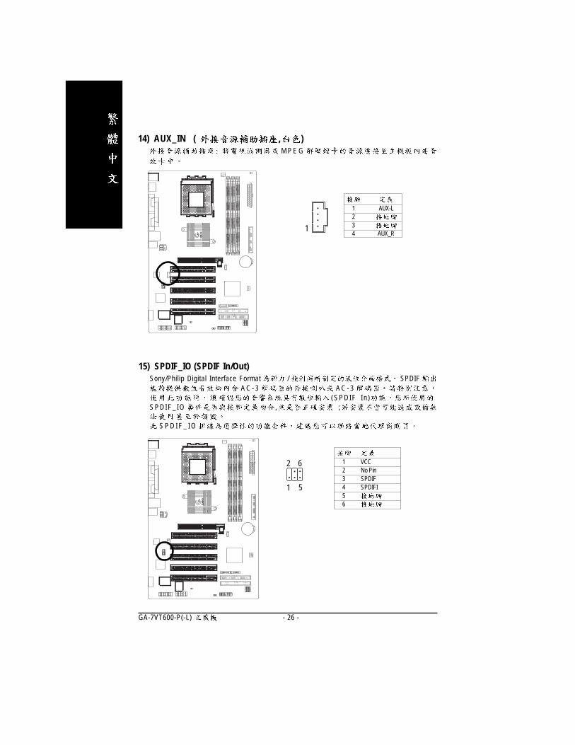
15) SPDIF_IO (SPDIF In/Out)Sony/Philip Digital Interface Format / SPDIF
A C - 3 A C - 3( S P D I F I n )
S P D I F _ I O , ;
S P D I F _ I O
1 VCC2 No Pin3 SPDIF4 SPDIFI56
1
62
5
1 AUX-L234 AUX_R
1
14) AUX_IN ( , )M P E G

- 27 -
1
2
15
16
17) GAME ( )
1
2 GRX1_R
3
4 GPSA2
5
6 GPX2_R
7 GPY2_R
8 MSI_R
9 GPSA1
10
11 GPY1_R
12
13 GPSB1
14 MSO_R
15 GPSB2
16
16) F_ USB1 / F_USB2( , )F _ U S B , ;
F _ U S B
1 Power2 Power3 USB DX-4 USB Dy-5 USB DX+6 USB Dy+789 No Pin10 USB Over Current
1
2
9
10

- 28 -GA-7VT600-P(-L)
19) CI (CASE OPEN)
.
1 Signal21
18)Modem *
1
12 VDD333 ACOUT4 VCC5 ACBCK6 +12V7 ADCIN8 VAUX339 ACDOUT10 NC11 ACSYNC12 NC13 ACRSTB14 No Pin
2
13
14
" * " GA-7VT600-P-L .

- 29 -

- 30 -GA-7VT600-P(-L)
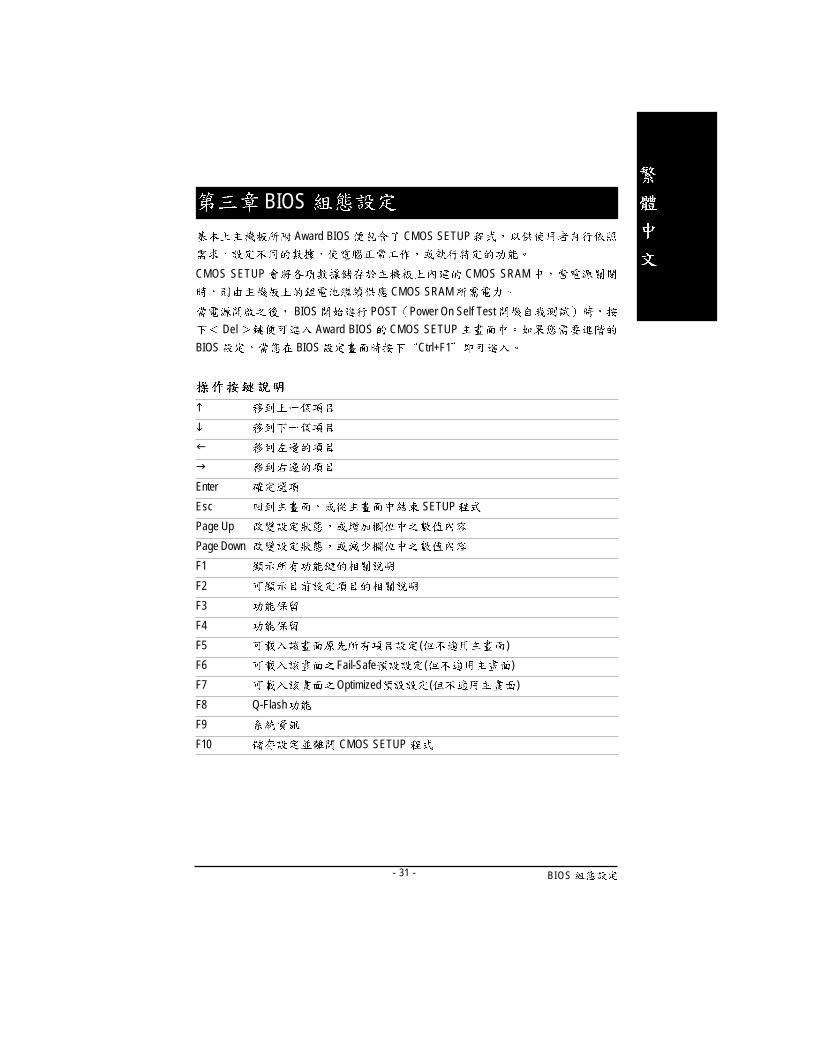
BIOS- 31 -
Award BIOS CMOS SETUP
CMOS SETUP CMOS SRAM
CMOS SRAM
BIOS POST Power On Self Test
Del Award BIOS CMOS SETUP
BIOS BIOS Ctrl+F1
BIOS
�
�
�
�
Enter
Esc SETUP
Page Up
Page Down
F1
F2
F3
F4
F5 ( )
F6 Fail-Safe ( )
F7 Optimized ( )
F8 Q-Flash
F9
F10 CMOS SETUP

- 32 -GA-7VT600-P(-L)
� Standard CMOS Features ( CMOS )
� Advanced BIOS features ( BIOS )
BIOS
....
1 :
S E T U P
S E T U P
F 1
B I O S C M O S S E T U P
< E s c >
(For Example BIOS Verson:F1)C M O S S E T U P ,
, E n t e r
CMOS Setup Utility-Copyright (C) 1984-2003 Award Software
�Standard CMOS Features Load Fail-Safe Defaults
�Advanced BIOS Features Load Optimized Defaults
�Integrated Peripherals Set Supervisor Password
�Power Management Setup Set User Password
�PnP/PCI Configurations Save & Exit Setup
�PC Health Status Exit Without Saving
�Frequency/Voltage Control
ESC:Quit ���� : Select Item
F8:Q-Flash F10:Save & Exit Setup
Time, Date, Hard Disk Type...

BIOS- 33 -
� Integrated peripherals ( )
COM Port IRQ LPT
Port SPP EPP ECP IDE PIO Mode ..
� Power management setup ( )
CPU GREEN
� PnP/PCI configuration ( PCI )
ISA PnP PCI
� PC Health Status ( )
,
� Frequency/Voltage Control ( / )
CPU
� Load Fail-Safe defaults ( Fail-Safe )
BIOS CMOS
� Load Optimized defaults ( Optimized )
Optimized CMOS
� Set Supervisor password ( )
SETUP CMOS
� Set User password ( )
PC BIOS
� Save & exit setup ( )
SETUP BIOS
F10
� Exit without save ( SETUP )
<ESC>
- 34 -GA-7VT600-P(-L)
C M O S
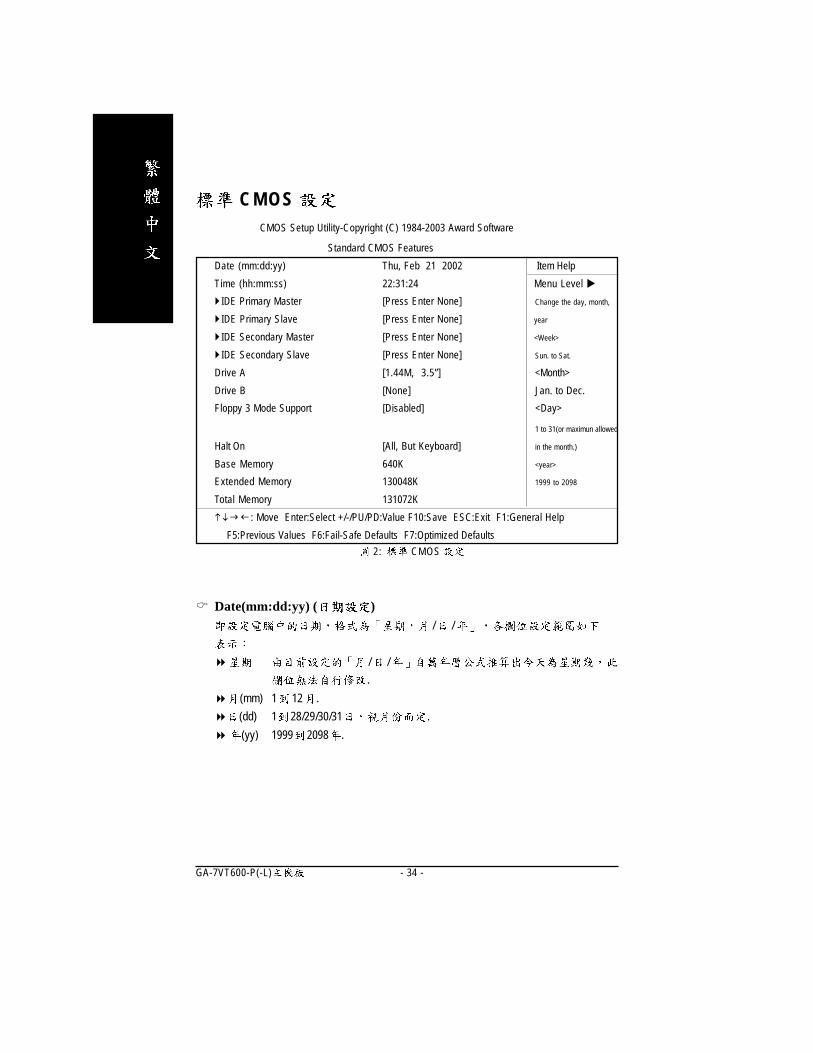
2: CMOS
� Date(mm:dd:yy) ( )/ /
� / /
.
� (mm) 1 12 .
� (dd) 1 28/29/30/31 .
� (yy) 1999 2098 .
CMOS Setup Utility-Copyright (C) 1984-2003 Award Software
Standard CMOS Features
Date (mm:dd:yy) Thu, Feb 21 2002 Item Help
Time (hh:mm:ss) 22:31:24 Menu Level �
� IDE Primary Master [Press Enter None] Change the day, month,
� IDE Primary Slave [Press Enter None] year
� IDE Secondary Master [Press Enter None] <Week>
� IDE Secondary Slave [Press Enter None] Sun. to Sat.
Drive A [1.44M, 3.5”] <Month>
Drive B [None] Jan. to Dec.
Floppy 3 Mode Support [Disabled] <Day>
1 to 31(or maximun allowed
Halt On [All, But Keyboard] in the month.)
Base Memory 640K <year>
Extended Memory 130048K 1999 to 2098
Total Memory 131072K
���� : Move Enter:Select +/-/PU/PD:Value F10:Save ESC:Exit F1:General Help
F5:Previous Values F6:Fail-Safe Defaults F7:Optimized Defaults
BIOS- 35 -
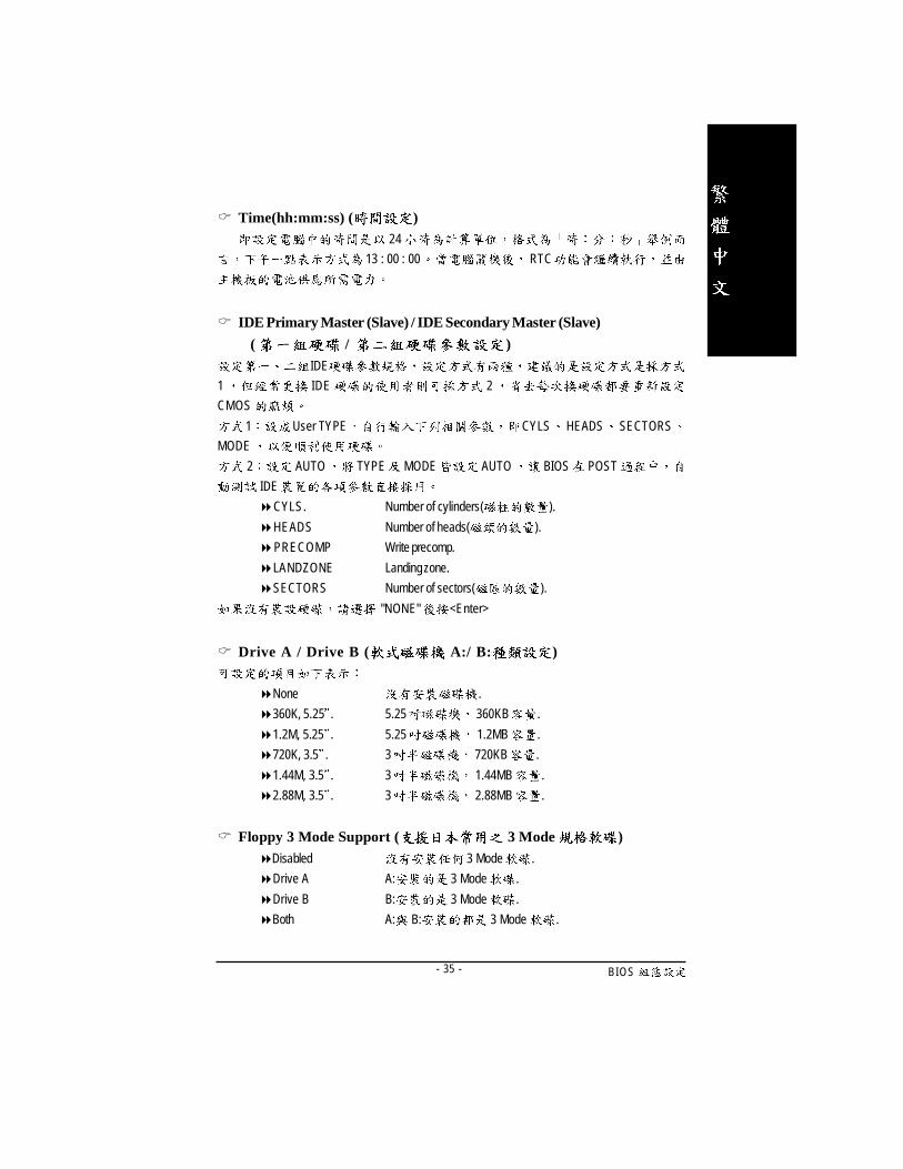
� Time(hh:mm:ss) ( )24
13 : 00 : 00 RTC
� IDE Primary Master (Slave) / IDE Secondary Master (Slave)
( / )IDE
1 IDE 2
CMOS
1 User TYPE CYLS HEADS SECTORS
MODE
2 AUTO TYPE MODE AUTO BIOS POST
IDE
�CYLS. Number of cylinders( ).
�HEADS Number of heads( ).
�PRECOMP Write precomp.
�LANDZONE Landing zone.
�SECTORS Number of sectors( ).
"NONE" <Enter>
� Drive A / Drive B ( A:/ B: )
�None .
�360K, 5.25 . 5.25 360KB .
�1.2M, 5.25 . 5.25 1.2MB .
�720K, 3.5 . 3 720KB .
�1.44M, 3.5 . 3 1.44MB .
�2.88M, 3.5 . 3 2.88MB .
� Floppy 3 Mode Support ( 3 Mode )�Disabled 3 Mode .
�Drive A A: 3 Mode .
�Drive B B: 3 Mode .
�Both A: B: 3 Mode .

- 36 -GA-7VT600-P(-L)
� Halt on( )
POST
�NO Errors
�All Errors
�All, But Keyboard
�All, But Diskette
�All, But Disk/Key
� Memory( )BIOS POST(Power On Self Test)
STANDARD CMOS SETUP
Base Memory
PC 640KB MS-DOS
Extended Memory
Base Other
Memory Module
BIOS- 37 -
BIOS
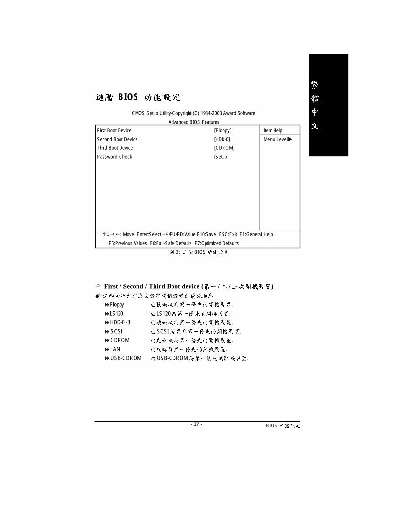
3: BIOS
� First / Second / Third Boot device ( / / )�
�Floppy .
�LS120 LS120 .
�HDD-0~3 .
�SCSI SCSI .
�CDROM .
�LAN .
�USB-CDROM USB-CDROM .
CMOS Setup Utility-Copyright (C) 1984-2003 Award Software
Advanced BIOS Features
First Boot Device [Floppy] Item Help
Second Boot Device [HDD-0] Menu Level�
Third Boot Device [CDROM]
Password Check [Setup]
���� : Move Enter:Select +/-/PU/PD:Value F10:Save ESC:Exit F1:General Help
F5:Previous Values F6:Fail-Safe Defaults F7:Optimized Defaults

- 38 -GA-7VT600-P(-L)
�USB-ZIP USB-ZIP .
�USB-FDD USB-FDD .
�USB-HDD USB-HDD .
�ZIP ZIP .
�Disabled .
� Password Check�System CMOS SETUP .
�Setup CMOS SETUP .( )
SETUP
Enter

BIOS- 39 -
CMOS Setup Utility-Copyright (C) 1984-2003 Award Software
Integrated Peripherals
OnChip IDE Channel0 [Enabled] Item Help
OnChip IDE Channel1 [Enabled] Menu Level�
OnChip Serial ATA [Enabled]
AC97 Audio [Enabled]
USB 1.1 Controller [Enabled]
USB 2.0 Controller [Enabled]
USB Keyboard Support [Disabled]
USB Mouse Support [Disabled]
Onboard H/W LAN * [Enabled]
Onboard LAN Boot ROM * [Disabled]
Onboard Modem Function * [Disabled]
Onboard Serial Port 1 [3F8/IRQ4]
Onboard Serial Port 2 [2F8/IRQ3]
Onboard Parallel Port [378/IRQ7]
Parallel Port Mode [SPP]
Game Port Address [201]
Mdi Port Address [330]
Midi Port IRQ [10]
���� : Move Enter:Select +/-/PU/PD:Value F10:Save ESC:Exit F1:General Help
F5:Previous Values F6:Fail-Safe Defaults F7:Optimized Defaults
Figure 4: Integrated Peripherals
" * " GA-7VT600-P-L .
- 40 -GA-7VT600-P(-L)
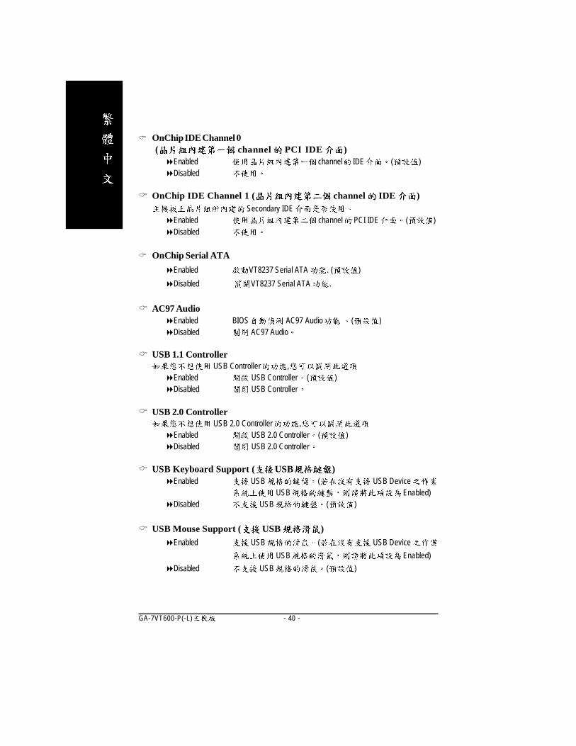
� OnChip IDE Channel 0 ( channel PCI IDE )
�Enabled channel IDE ( )�Disabled
� OnChip IDE Channel 1 ( channel IDE )Secondary IDE
�Enabled channel PCI IDE ( )�Disabled
� OnChip Serial ATA
�Enabled VT8237 Serial ATA . ( )
�Disabled VT8237 Serial ATA .
� AC97 Audio�Enabled BIOS AC97 Audio ( )�Disabled AC97 Audio
� USB 1.1 ControllerUSB Controller ,
�Enabled USB Controller ( )�Disabled USB Controller
� USB 2.0 ControllerUSB 2.0 Controller ,
�Enabled USB 2.0 Controller ( )�Disabled USB 2.0 Controller
� USB Keyboard Support ( USB )�Enabled USB ( USB Device
USB Enabled)�Disabled USB ( )
� USB Mouse Support ( USB )�Enabled USB ( USB Device
USB Enabled)
�Disabled USB ( )
BIOS- 41 -
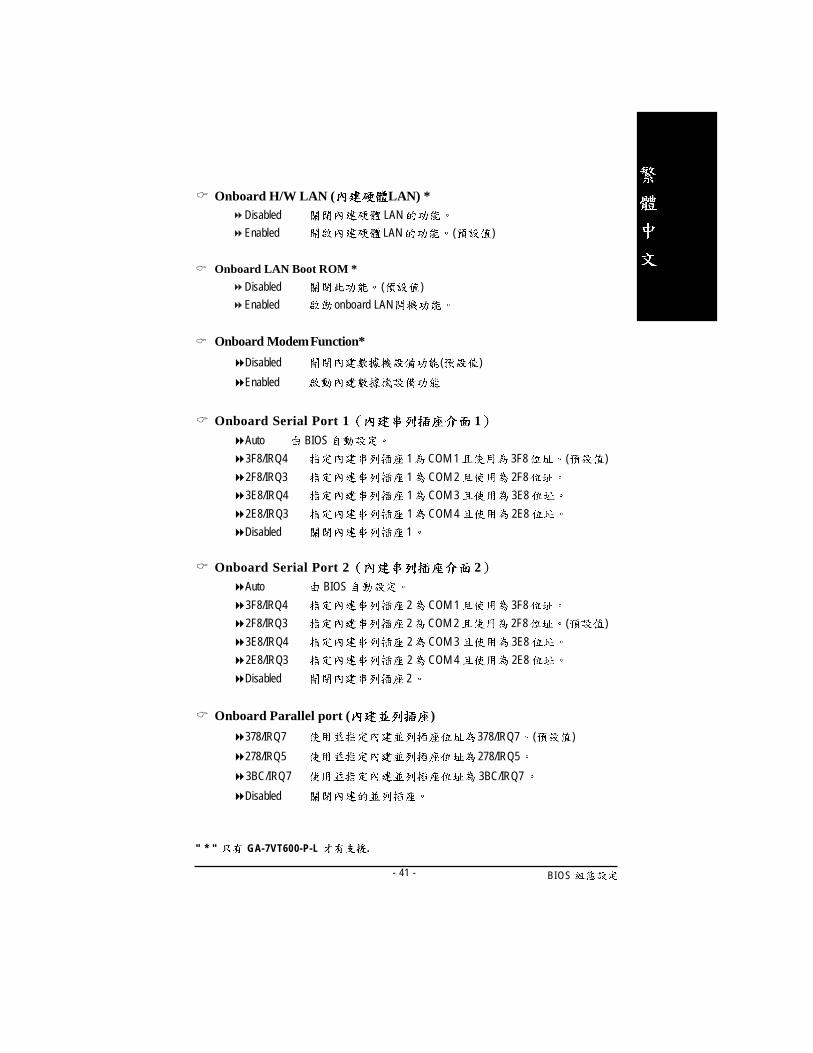
� Onboard H/W LAN ( LAN) *Disabled LAN
Enabled LAN ( )
� Onboard LAN Boot ROM *
Disabled ( )
Enabled onboard LAN
� Onboard Modem Function*
�Disabled ( )
�Enabled
� Onboard Serial Port 1 1�Auto BIOS
�3F8/IRQ4 1 COM 1 3F8 ( )
�2F8/IRQ3 1 COM 2 2F8
�3E8/IRQ4 1 COM 3 3E8
�2E8/IRQ3 1 COM 4 2E8
�Disabled 1
� Onboard Serial Port 2 2�Auto BIOS
�3F8/IRQ4 2 COM 1 3F8
�2F8/IRQ3 2 COM 2 2F8 ( )
�3E8/IRQ4 2 COM 3 3E8
�2E8/IRQ3 2 COM 4 2E8
�Disabled 2
� Onboard Parallel port ( )
�378/IRQ7 378/IRQ7 ( )
�278/IRQ5 278/IRQ5
�3BC/IRQ7 3BC/IRQ7
�Disabled
" * " GA-7VT600-P-L .
- 42 -GA-7VT600-P(-L)
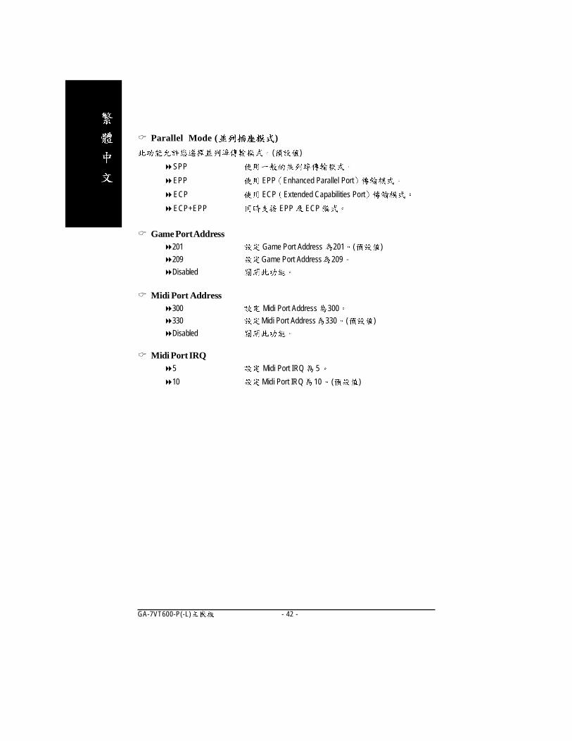
� Parallel Mode ( )
( )
�SPP
�EPP EPP Enhanced Parallel Port
�ECP ECP Extended Capabilities Port
�ECP+EPP EPP ECP
� Game Port Address�201 Game Port Address 201 ( )
�209 Game Port Address 209
�Disabled
� Midi Port Address�300 Midi Port Address 300
�330 Midi Port Address 330 ( )
�Disabled
� Midi Port IRQ�5 Midi Port IRQ 5
�10 Midi Port IRQ 10 ( )

BIOS- 43 -
CMOS Setup Utility-Copyright (C) 1984-2003 Award Software
Power Management Setup
ACPI Suspend Type [S1(POS)] Item Help
�USB Device Wake-Up From S3 Disabled Menu Level�
Power LED in S1 state [Blinking]
Soft-Off by PWRBTN [Instant-off]
AC Back Function [Soft-Off]
Keyboard Power On [Disabled]
Mouse Power On [Disabled]
PME Event Wake Up [Enabled]
ModemRingOn/WakeOnLAN* [Enabled]
Resume by Alarm [Disabled]
� Date(of Month) Alarm Everyday
� Time(hh:mm:ss) Alarm 0 : 0 : 0
���� : Move Enter:Select +/-/PU/PD:Value F10:Save ESC:Exit F1:General Help
F5:Previous Values F6:Fail-Safe Defaults F7:Optimized Defaults
Figure 5: Power Management Setup
" * " GA-7VT600-P-L .

- 44 -GA-7VT600-P(-L)
� ACPI Suspend Type�S1(POS) ACPI Suspend type S1(Power On Suspend) ( ).
�S3(STR) ACPI Suspend type S3(Suspend to RAM).
�USB Device Wakeup From S3( ACPI Suspend Type S3(STR))�Enabled S3 USB
�Disabled ( )
� Power LED in S1 state�Blinking Power LED S1
( )
�Dual/Off
power LED LED
power LED LED
� Soft-off by PWRBTN ( )�Instant-off Soft-off ( )
�Delay 4 Sec. Soft-off 4
� AC Back Function ,�Memory
�Full-On
�Soft-Off SoftPower Button
� Keyboard Power On ( )�Password 1-8
�Disabled ( )
�Keyboard 98 Windows 98 power
� Mouse Power On ( )�Enabled
�Disabled ( )
BIOS- 45 -
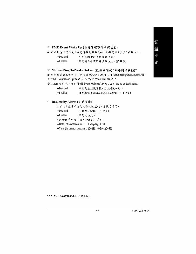
� PME Event Wake Up ( )
� +5VSB 1
�Disabled
�Enabled ( )
� ModemRingOn/WakeOnLan ( / )*� WOL , "ModemRingOn/WakeOnLAN
"PME Event Wake up" , / Wake on LAN .
, "PME Event Wake up , / Wake on LAN .
�Disabled /
�Enabled / ( )
� Resume by Alarm ( )Enabled
�Disabled ( )
�Enabled
:
�Date ( of Month) Alarm : Everyday, 1~31
�Time ( hh: mm: ss) Alarm : (0~23) : (0~59) : (0~59)
" * " GA-7VT600-P-L .

- 46 -GA-7VT600-P(-L)
P C I
6: PC I
� PCI1/PCI5 IRQ Assignment�Auto IRQ PCI 1/PCI5. ( )
�3,4,5,7,9.,10,11,12,14,15 Set 3,4,5,7,9,10,11,12,14,15 to PCI1/PCI5.
� PCI2 IRQ Assignment�Auto IRQ PCI 2. ( )
�3,4,5,7,9.,10,11,12,14,15 Set 3,4,5,7,9,10,11,12,14,15 to PCI2.
� PCI3 IRQ Assignment�Auto IRQ PCI 3. ( )
�3,4,5,7,9.,10,11,12,14,15 Set 3,4,5,7,9,10,11,12,14,15 to PCI 3.
� PCI4 IRQ Assignment�Auto IRQ PCI 4. ( )
�3,4,5,7,9.,10,11,12,14,15 Set 3,4,5,7,9,10,11,12,14,15 to PCI 4.
CMOS Setup Utility-Copyright (C) 1984-2003 Award Software
PnP/PCI Configurations
PCI1/PCI5 IRQ Assignment [Auto] Item Help
PCI2 IRQ Assignment [Auto] Menu Level�
PCI3 IRQ Assignment [Auto]
PCI4 IRQ Assignment [Auto]
���� : Move Enter:Select +/-/PU/PD:Value F10:Save ESC:Exit F1:General Help
F5:Previous Values F6:Fail-Safe Defaults F7:Optimized Defaults
BIOS- 47 -
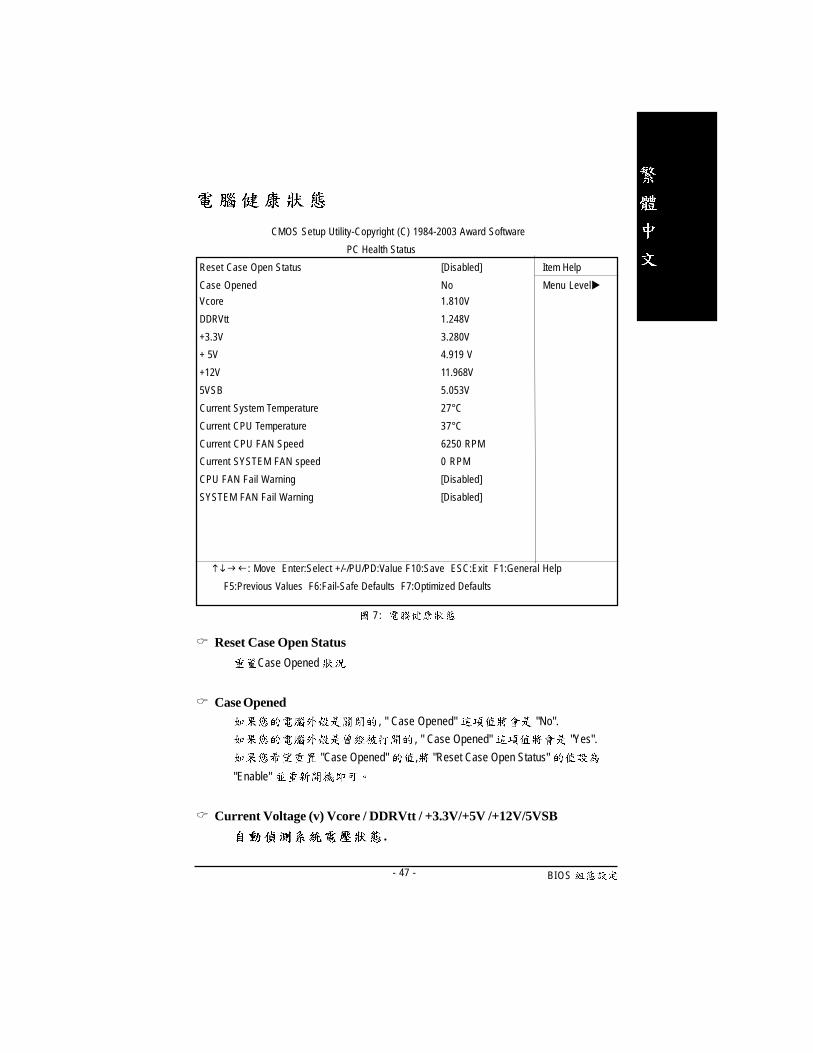
7 :
� Reset Case Open Status
Case Opened
� Case Opened, " Case Opened" "No".
, " Case Opened" "Yes".
"Case Opened" , "Reset Case Open Status"
"Enable"
� Current Voltage (v) Vcore / DDRVtt / +3.3V/+5V /+12V/5VSB
.
CMOS Setup Utility-Copyright (C) 1984-2003 Award Software
PC Health Status
Reset Case Open Status [Disabled] Item Help
Case Opened No Menu Level�
Vcore 1.810V
DDRVtt 1.248V
+3.3V 3.280V
+ 5V 4.919 V
+12V 11.968V
5VSB 5.053V
Current System Temperature 27°C
Current CPU Temperature 37°C
Current CPU FAN Speed 6250 RPM
Current SYSTEM FAN speed 0 RPM
CPU FAN Fail Warning [Disabled]
SYSTEM FAN Fail Warning [Disabled]
���� : Move Enter:Select +/-/PU/PD:Value F10:Save ESC:Exit F1:General Help
F5:Previous Values F6:Fail-Safe Defaults F7:Optimized Defaults

- 48 -GA-7VT600-P(-L)
� Fan Fail Alarm (CPU/System )
�Enabled CPU / System .
�Disabled CPU / System . ( )
� Current System Temperature
.
� Current CPU Temperature
CPU .
� CPU FAN / System FAN Speed (RPM)
.

BIOS- 49 -
/
8 : /
� Spread spectrum Modulated( )�Disable .�Enable . ( )
� CPU Host Clock Control�Disable CPU Host Clock .( )�Enable CPU Host Clock .
�
CMOS , 20
. CPU .
� "CPU Host Clock Control" Enabled
CMOS Setup Utility-Copyright (C) 1984-2003 Award Software
Frequency/Voltage Control
Spread spectrum Modulated [Enabled] Item Help
CPU Host Clock Control [Disabled] Menu Level�
�CPU Host Frequency(MHz) 100
�PCI/AGP Frequency(MHz) 33/66
DRAM Clock(MHz) [Auto]
CPU Voltage Control [Auto]
AGP OverVoltage Control [Auto]
DIMM OverVoltage Control [Auto]
���� : Move Enter:Select +/-/PU/PD:Value F10:Save ESC:Exit F1:General Help
F5:Previous Values F6:Fail-Safe Defaults F7:Optimized Defaults
- 50 -GA-7VT600-P(-L)
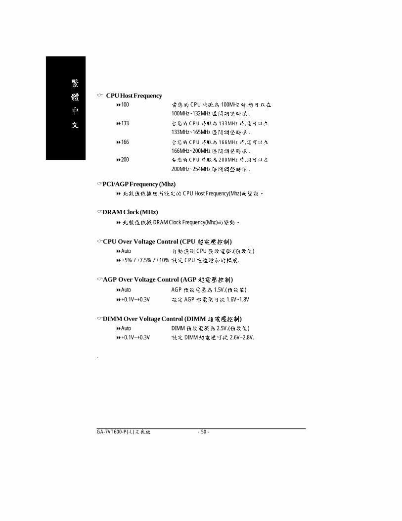
� CPU Host Frequency�100 CPU 100MHz ,
100MHz~132MHz .
�133 CPU 133MHz ,
133MHz~165MHz .
�166 CPU 166MHz ,
166MHz~200MHz .
�200 CPU 200MHz ,
200MHz~254MHz .
�PCI/AGP Frequency (Mhz)� CPU Host Frequency(Mhz)
�DRAM Clock (MHz)
� DRAM Clock Frequency(Mhz)
�CPU Over Voltage Control (CPU )�Auto CPU .( )
�+5% / +7.5% / +10% CPU .
�AGP Over Voltage Control (AGP )
�Auto AGP 1.5V.( )
�+0.1V~+0.3V AGP 1.6V~1.8V
�DIMM Over Voltage Control (DIMM )�Auto DIMM 2.5V.( )
�+0.1V~+0.3V DIMM 2.6V~2.8V.
.
BIOS- 51 -
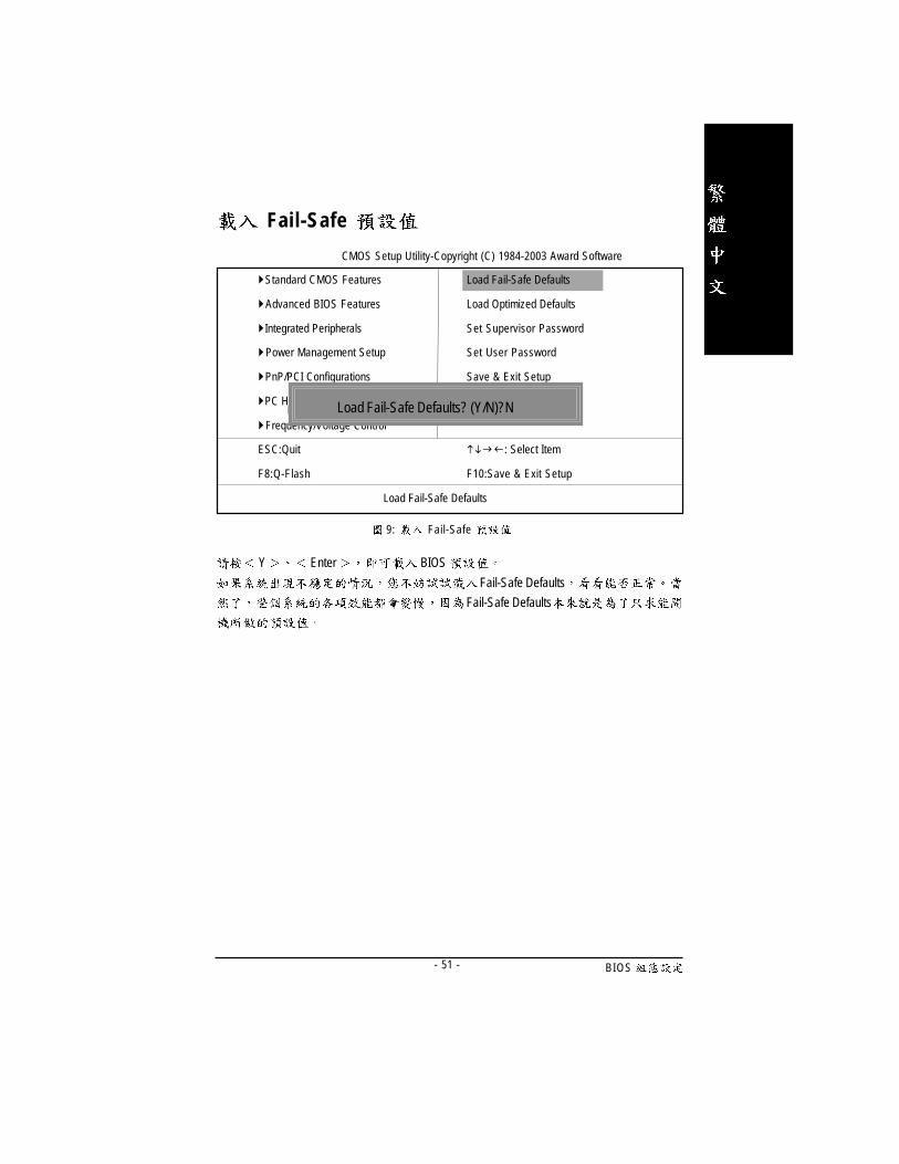
Fail-Safe
9: Fail-Safe
Y Enter BIOS
Fail-Safe Defaults
Fail-Safe Defaults
CMOS Setup Utility-Copyright (C) 1984-2003 Award Software
�Standard CMOS Features Load Fail-Safe Defaults
�Advanced BIOS Features Load Optimized Defaults
�Integrated Peripherals Set Supervisor Password
�Power Management Setup Set User Password
�PnP/PCI Configurations Save & Exit Setup
�PC Health Status Exit Without Saving
�Frequency/Voltage Control
ESC:Quit ����: Select Item
F8:Q-Flash F10:Save & Exit Setup
Load Fail-Safe Defaults
Figure 11: Load Fail-Safe DefaultsLoad Fail-Safe Defaults? (Y/N)?N

- 52 -GA-7VT600-P(-L)
Optimized
Y Enter
Load Optimized Defaults CMOS
10: Optimized
CMOS Setup Utility-Copyright (C) 1984-2003 Award Software
�Standard CMOS Features Load Fail-Safe Defaults
�Advanced BIOS Features Load Optimized Defaults
�Integrated Peripherals Set Supervisor Password
�Power Management Setup Set User Password
�PnP/PCI Configurations Save & Exit Setup
�PC Health Status Exit Without Saving
�Frequency/Voltage Control
ESC:Quit ����: Select Item
F8:Q-Flash F10:Save & Exit Setup
Load Optimized Defaults
Figure 11: Load Fail-Safe DefaultsLoad Optimized Defaults? (Y/N)?N

BIOS- 53 -
(Supervisor) / (User)
11: (Supervisor)/ (User)
8 Enter BIOS
Enter BIOS
PASSWORD DISABLED
� SUPERVISOR Supervisor Advanced BIOS Features Security op
tion SETUP CMOS SETUP Supervisor
� USER User Advanced BIOS Features Password Check
SYSTEM User Supervisor
CMOS SETUP USER Password
BIOS Supervisor CMOS SETUP
CMOS Setup Utility-Copyright (C) 1984-2003 Award Software
�Standard CMOS Features Top Performance
�Advanced BIOS Features Load Fail-Safe Defaults
�Integrated Peripherals Load Optimized Defaults
�Power Management Setup Set Supervisor Password
�PnP/PCI Configurations et User Password
�PC Health Status Save & Exit Setup
�Frequency/Voltage Control Exit Without Saving
ESC:Quit F3:Change Language
F8:Q-Flash F10:Save & Exit Setup
Change/Set/Disable Password
Figure 11: Load Fail-Safe DefaultsEnter Password:

- 54 -GA-7VT600-P(-L)
S E T U P
Y Enter RTC CMOS Setup Utility
N Esc
12: SETUP
CMOS Setup Utility-Copyright (C) 1984-2003 Award Software
�Standard CMOS Features Load Fail-Safe Defaults
�Advanced BIOS Features Load Optimized Defaults
�Integrated Peripherals Set Supervisor Password
�Power Management Setup Set User Password
�PnP/PCI Configurations Save & Exit Setup
�PC Health Status Exit Without Saving
�Frequency/Voltage Control
ESC:Quit ����: Select Item
F8:Q-Flash F10:Save & Exit Setup
Save Data to CMOS
Save to CMOS and EXIT (Y/N)? Y
BIOS- 55 -
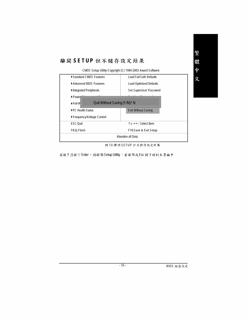
S E T U P
Y Enter Setup Utility N Esc
1 3 : S E T U P
CMOS Setup Utility-Copyright (C) 1984-2003 Award Software
�Standard CMOS Features Load Fail-Safe Defaults
�Advanced BIOS Features Load Optimized Defaults
�Integrated Peripherals Set Supervisor Password
�Power Management Setup Set User Password
�PnP/PCI Configurations Save & Exit Setup
�PC Health Status Exit Without Saving
�Frequency/Voltage Control
ESC:Quit ����: Select Item
F8:Q-Flash F10:Save & Exit Setup
Abandon all Data
Quit Without Saving (Y/N)? N

- 56 -GA-7VT600-P(-L)
- 57 -
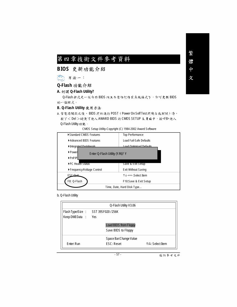
A. Q-Flash Utility?Q-Flash BIOS BIOS
B. Q-Flash Utilitya. BIOS POST Power On Self Test
Del AWARD BIOS CMOS SETUP <F8>
Q-Flash Utility
b. Q-Flash Utility
Q-Flash Utility V3.06
Flash Type/Size : SST 39SF020 / 256K
Keep DMI Data : Yes
Space Bar:Change Value
Enter: Run ESC: Reset �/�: Select Item
Load BIOS from Floppy
Save BIOS to Floppy
CMOS Setup Utility-Copyright (C) 1984-2002 Award Software
�Standard CMOS Features Top Performance
�Advanced BIOS Features Load Fail-Safe Defaults
�Integrated Peripherals Load Optimized Defaults
�Power Management Setup Set Supervisor Password
�PnP/PCI Configurations Set User Password
�PC Health Status Save & Exit Setup
�Frequency/Voltage Control Exit Without Saving
ESC:Quit ����:Select Item
F8: Q-Flash F10:Save & Exit Setup
Time, Date, Hard Disk Type...
Enter Q-Flash Utility (Y/N)? Y
Q-Flash
BIOS

- 58 -GA-7VT600-P(-L)
Load BIOS From Floppy (BIOS )� BIOS A: <Enter>
XXXX.XX 256K
Total Size: 1.39M Free Size: 1.14M
F5: Refresh DEL: Delete ESC: Return Main
1 File(s) found
XXXX.XX BIOS
!! BIOS
� <Enter>
Are you sure to update BIOS?
[Enter] to contiune Or [ESC] ot abort...
!! COPY BIOS Completed -Pass !!
Please press any key to continue
BIOS <Enter>
<Esc>
- 59 -
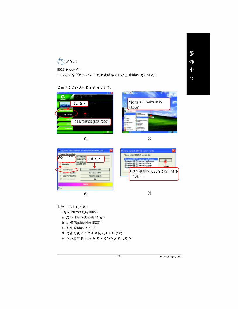
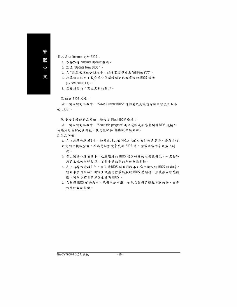
:
BIOS
DOS @BIOS
1.
I. Internet BIOS
a. "Internet Update"
b. "Update New BIOS"
c. @BIOS
d.
e. BIOS
(1) (2)
(3)
1.Click "@BIOS (B02102201).
(4)
.
2. "@BIOS Writer Utility
v.1.08q"
"�"
3. @BIOS
OK
- 60 -GA-7VT600-P(-L)
II. Internet BIOS
a. "Internet Update"
b. "Update New BIOS"
c. " "All Files (*.*)"
d. BIOS
( :7VT600-P.F1)
e.
III. BIOS
"Save Current BIOS"
BIOS
IV. Flash ROM
"About this program" @BIOS
Flash ROM
2.
a. I ( )
BIOS
b. II BIOS
c. I @BIOS BIOS
BIOS
II BIOS
d. BIOS
- 61 -
@BIOSTM BIOS
EasyTune IIITM
DOS BIOS Windows
@BIOSTM BIOS
@BIOSTM BIOS
@BIOSTM Internet BIOS BIOS
Windows BIOS !
@BIOSTM BIOS
@ BIOSTM

- 62 -GA-7VT600-P(-L)
EasyTune 4
BIOS CPU Jumper
PC
EasyTune 4 Jumper
BIOS Windows
EasyTune 4 Easy Mode
Advanced Mode Easy Mode
Auto Optimize EasyTune 4 CPU
Advanced Mode AGP
EasyTune 4 EasyTune 4
Windows EasyTune 4
EasyTune 4
EasyTune 4
1.
2.
Easy TuneTM 4

- 63 -
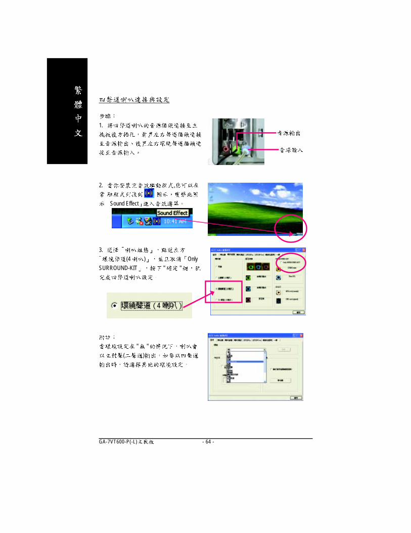
3.
(2 ) " "
1.
2. ,
Sound Effect
( Windows98SE/2000/ME/XP)
/ /
- 64 -GA-7VT600-P(-L)
" "
( )
1.
3.
(4 ) Only
SURROUND-KIT " "
2. ,
Sound Effect
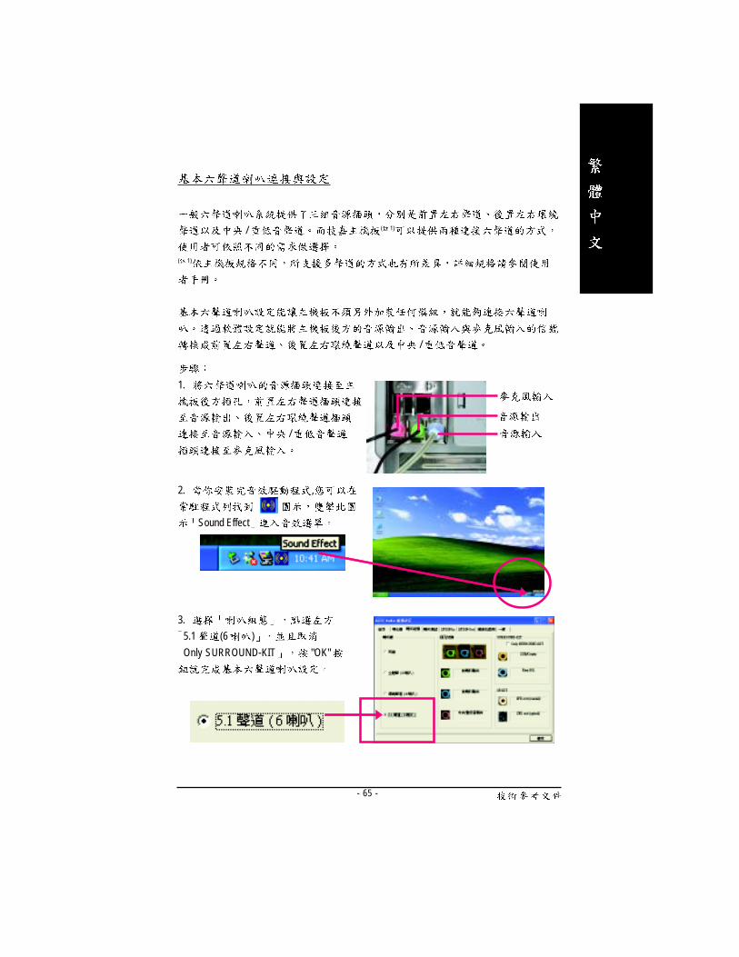
- 65 -
/ ( 1)
( 1)
/
1.
/
2. ,
Sound Effect
3.
5.1 (6 )
Only SURROUND-KIT "OK"

- 66 -GA-7VT600-P(-L)
1. Audio Combo Kit
( 6 )
(
OK )
Audio Combo Kit 6
2. SURROUND-KIT SUR_CEN
3.
SURROUND-KIT REAR R/L
/
SURROUND-KIT SUB CENTER
( Audio Combo Kit, )
(Audio Combo Kit, SPDIF output : SOURROUND-Kit:
/ )

- 67 -
5.
5.1 (6 )
Only SURROUND-KIT
" "
4. Sound Effect
:
" "
( )
- 68 -GA-7VT600-P(-L)
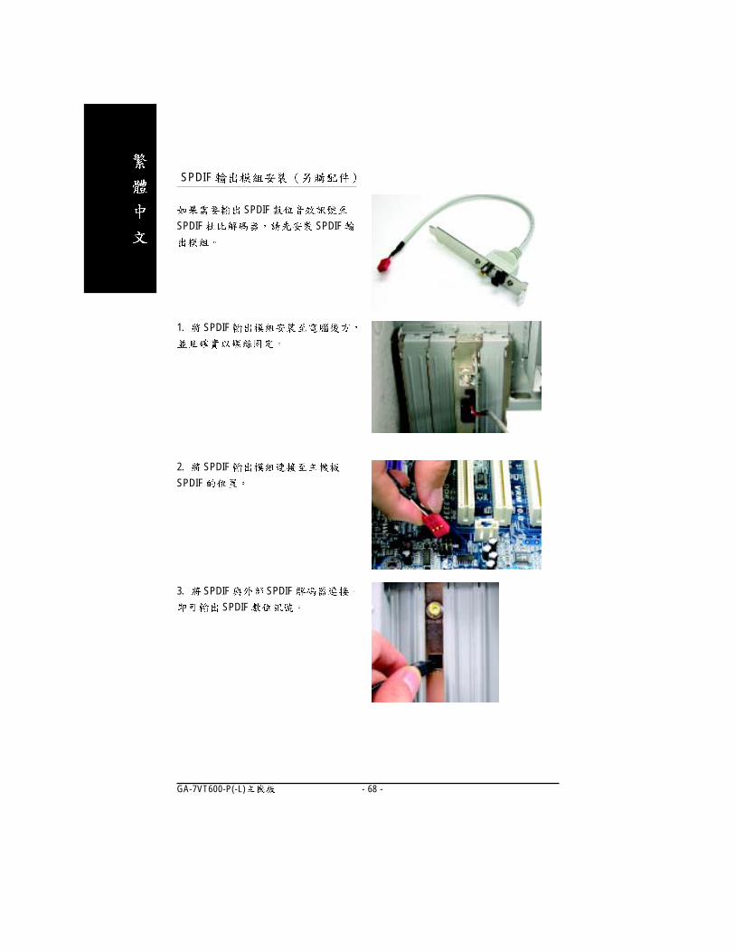
SPDIF
3. SPDIF SPDIF
SPDIF
1. SPDIF
2. SPDIF
SPDIF
SPDIF
SPDIF SPDIF

- 69 -
Jack-Sensing
Windows 98/98 SE/2000/ME DirectX 8.1
Jack-Sensing 2-channel
( Windows XP)
Jack-Sensing
- 70 -GA-7VT600-P(-L)
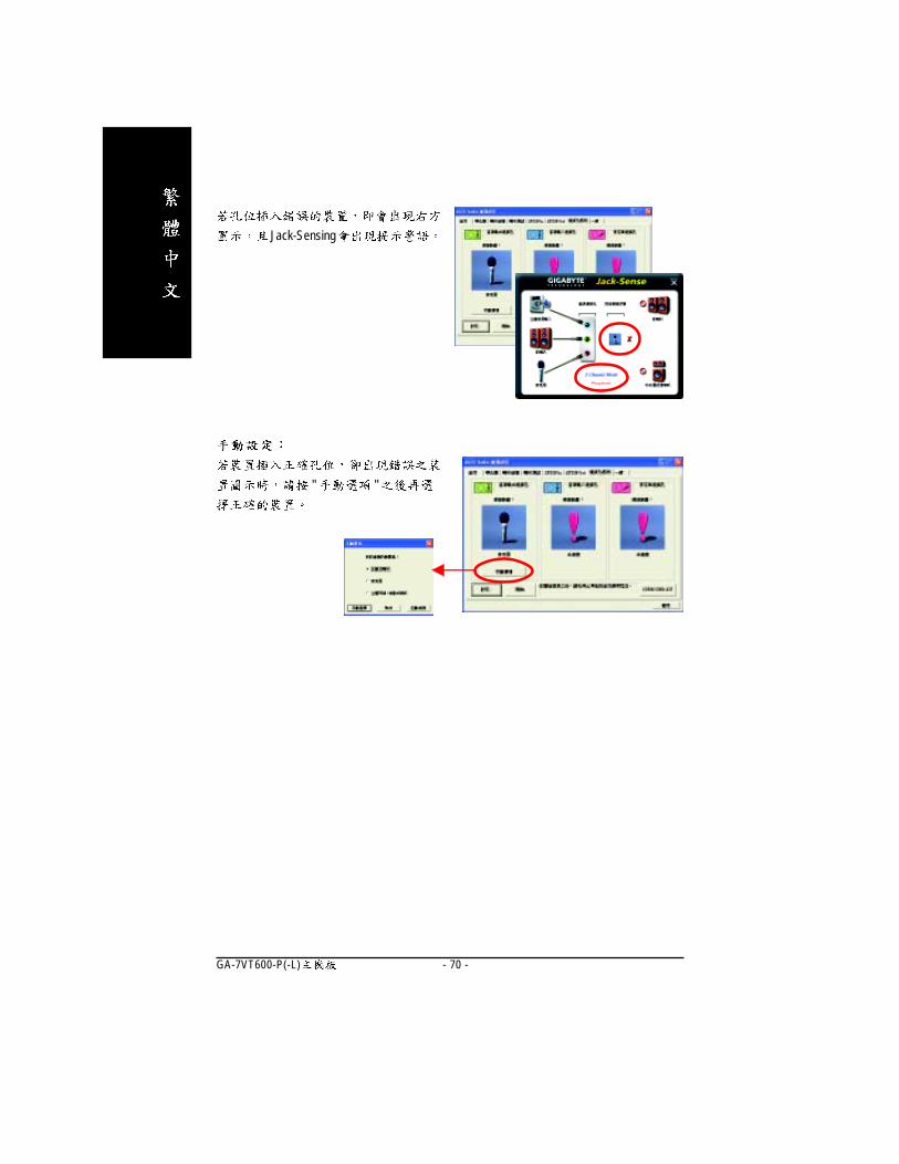
" "
Jack-Sensing

- 71 -
Xpress Recovery Xpress Recovery?
,
, , ,
, ,
1. FAT16 FAT32 NTFS
2. IDE1 Master
3.
4. HPA IDE
5. (Partition) , ,
(Partition)
6. Ghost NTFS , Xpress
Recovery
1.
2. ,
Xpress Recovery
Xpress Recovery
Xpress Recovery : ( )
1. F9
BIOS Advanced BIOS CD-ROM ,
, Boot from CD: , Xpress
Rcovery
2. BIOS CD-ROM
(power on self test) F9
Boot from CD:
.
.Verifying DMI Pool DataBoot from CD:
Award Modular BIOS v6.00PG, An Energy Star Al lyCopyright (C) 1984-2002, Award Software, Inc.
Intel 865PE AGPSet BIOS for 8IPE1000MT F1Check System Health OK...
Press DEL to enter SETUP / Q-Flash, F9 For Xpress Recovery08/16/2002-I845GE-6A69YG01C-00
F9 For Xpress Recovery
- 72 -GA-7VT600-P(-L)
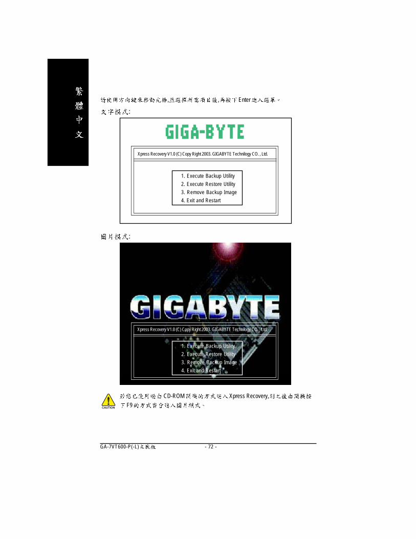
, , Enter
CD-ROM Xpress Recovery,
F9
:
Xpress Recovery V1.0 (C) Copy Right 2003. GIGABYTE Technilogy CO. , Ltd.
1. Execute Backup Utility
2. Execute Restore Utility
3. Remove Backup Image
4. Exit and Restart
Xpress Recovery V1.0 (C) Copy Right 2003. GIGABYTE Technilogy CO. , Ltd.
1. Execute Backup Utility
2. Execute Restore Utility
3. Remove Backup Image
4. Exit and Restart
:

- 73 -
1.Execute Backup Utility:
� Press B to Backup your System or Esc to Exit
,
2.Execute Restore Utility:
� This program will recover your system to factory default.
Press R to recover your system.
Press Esc to exit
3.Remove Backup Image:
� Are you sure to remove backup image? (Y/N)
4.Exit and Restart:
- 74 -GA-7VT600-P(-L)

- 75 -
Revision History
Windows XP ( 2.2)
( " "
setup.exe )
"Xpress Install"
"Xpress Install"
"Xpress Install" " " " "
- 76 -GA-7VT600-P(-L)
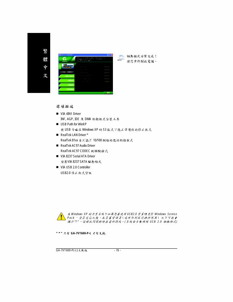
� VIA 4IN1 Driver
INF, AGP, IDE DMA
� USB Path for WinXP
USB Windows XP S3
� RealTek LAN Driver *
RealTek 81xx 10/100
� RealTek AC97 Audio Driver
RealTek AC97 CODEC
� VIA 8237 Serial ATA Driver
VIA 8237 SATA
� VIA USB 2.0 Controller
USB2.0
Revision History
" * " GA-7VT600-P-L .
Windows XP USB2.0 Windows ServiceP a c k \ \
"? " ( USB 2 .0 )
- 77 -
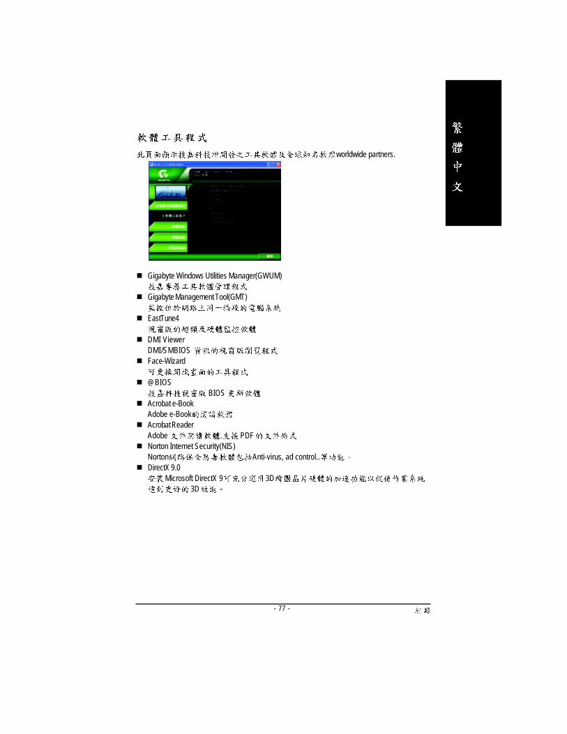
worldwide partners.
� Gigabyte Windows Utilities Manager(GWUM)
� Gigabyte Management Tool(GMT)
� EastTune4
� DMI ViewerDMI/SMBIOS
� Face-Wizard
� @BIOSBIOS
� Acrobat e-BookAdobe e-Book
� Acrobat ReaderAdobe . PDF
� Norton Internet Security(NIS)Norton Anti-virus, ad control..
� DirectX 9.0Microsoft DirectX 9 3D
3D
- 78 -GA-7VT600-P(-L)
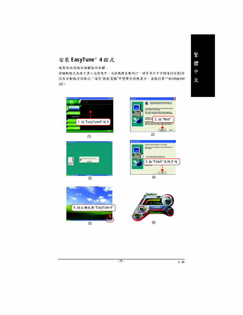
- 79 -
(
" " setup.exe
)
(1) (2)
(4)
1. "EasyTune4"2. "Next"
(3)
(6)(5)
3. "Finish"
4. "EasyTune 4"
EasyTune 4

- 80 -GA-7VT600-P(-L)
" "
( http://tw.giga-byte.com/chinese-web/faq/faq.htm)
BIOS
BIOS "Del" BIOS
"Ctrl + F1",
/
/
EasyTuneTM
4
EasyTuneTM
4
EasyTuneTM
4
RAID Win2000/XP
IDE 3 4 RAID ATA ?
RAID
( http://tw.giga-byte.com/chinese-web/support/user_pdf/raid_manual.pdf )

- 81 -
CMOS
Clear CMOS
CMOS CMOS
CMOS CMOS
( )
)
Del BIOS Load Fail-Safe Defaults
BIOS BIOS
BIOS ?
BIOS BIOS "Load Fail-Safe Defaults"
( Load BIOS Defaults"
CMOS
IDE2?
F_USB(Front USB) USB Over Current
- 82 -GA-7VT600-P(-L)
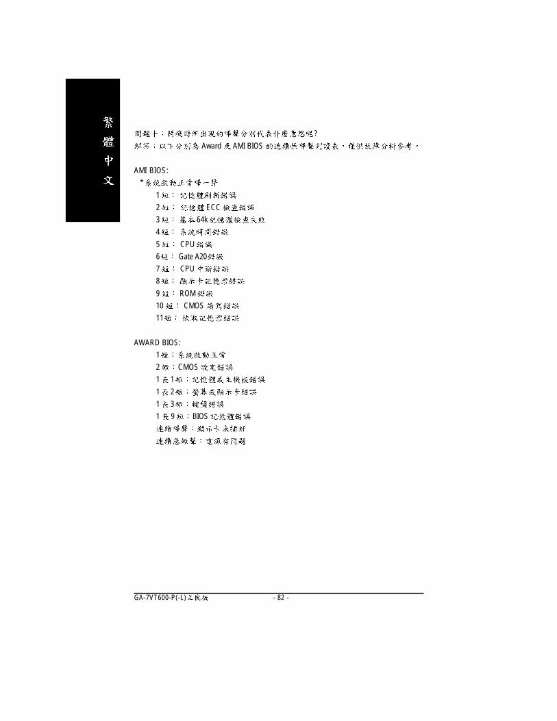
?
Award AMI BIOS
AMI BIOS:
*
1
2 ECC
3 64k
4
5 CPU
6 Gate A20
7 CPU
8
9 ROM
10 CMOS
11
AWARD BIOS:
1
2 CMOS
1 1
1 2
1 3
1 9 BIOS
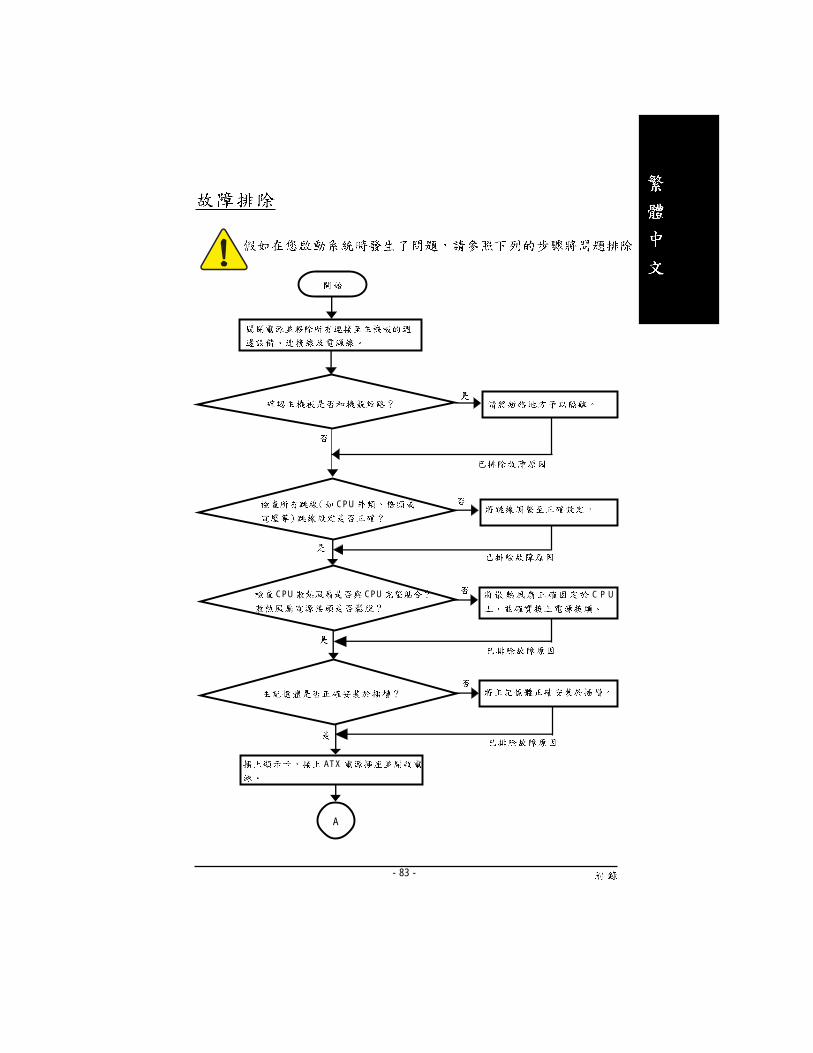
- 83 -
CPU
CPU CPU C P U
AT X
A

- 84 -GA-7VT600-P(-L)
<Del> BIOS Load
Optimized Defaults
IDE IDE
CPU
CPU
CPU
A
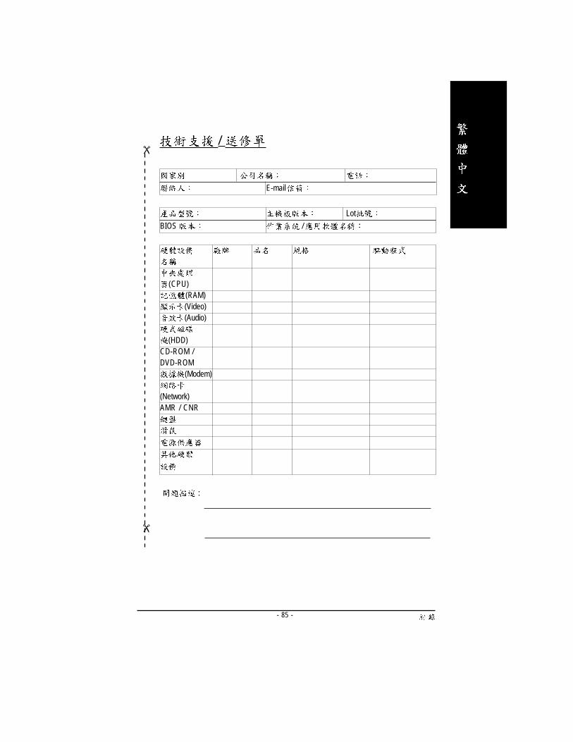
- 85 -
��
Lot
BIOS /
(CPU)(RAM)(Video)(Audio)
(HDD)CD-ROM /DVD-ROM
(Modem)
(Network)AMR / CNR
:
/
- 86 -GA-7VT600-P(-L)
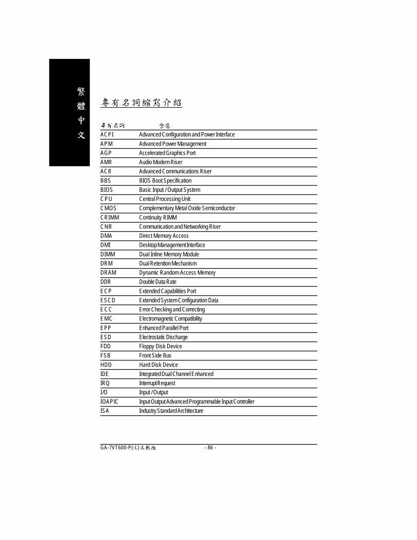
ACPI Advanced Configuration and Power Interface
APM Advanced Power Management
AGP Accelerated Graphics Port
AMR Audio Modem Riser
ACR Advanced Communications Riser
BBS BIOS Boot Specification
BIOS Basic Input / Output System
CPU Central Processing Unit
CMOS Complementary Metal Oxide Semiconductor
CRIMM Continuity RIMM
CNR Communication and Networking Riser
DMA Direct Memory Access
DMI Desktop Management Interface
DIMM Dual Inline Memory Module
DRM Dual Retention Mechanism
DRAM Dynamic Random Access Memory
DDR Double Data Rate
ECP Extended Capabilities Port
ESCD Extended System Configuration Data
ECC Error Checking and Correcting
EMC Electromagnetic Compatibility
EPP Enhanced Parallel Port
ESD Electrostatic Discharge
FDD Floppy Disk Device
FSB Front Side Bus
HDD Hard Disk Device
IDE Integrated Dual Channel Enhanced
IRQ Interrupt Request
I/O Input / Output
IOAPIC Input Output Advanced Programmable Input Controller
ISA Industry Standard Architecture
Revision History

- 87 -
LAN Local Area Network
LBA Logical Block Addressing
LED Light Emitting Diode
MHz Megahertz
MIDI Musical Instrument Digital Interface
MTH Memory Translator Hub
MPT Memory Protocol Translator
NIC Network Interface Card
OS Operating System
OEM Original Equipment Manufacturer
PAC PCI A.G.P. Controller
POST Power-On Self Test
PCI Peripheral Component Interconnect
RIMM Rambus in-line Memory Module
SCI Special Circumstance Instructions
SECC Single Edge Contact Cartridge
SRAM Static Random Access Memory
SMP Symmetric Multi-Processing
SMI System Management Interrupt
USB Universal Serial Bus
VID Voltage ID

- 88 -GA-7VT600-P(-L)

- 89 -

- 90 -GA-7VT600-P(-L)

- 91 -
�
6
886 (2) 8912-4888
886 (2) 8912-4004
: http://tw.giga-byte.com
�
G.B.T. INC.
17358 Railroad St, City of Industry, CA 91748.
1 (626) 854-9338
1 (626) 854-9339
http://us.giga-byte.com
�
G.B.T. Technology Trading GmbH
49-40-2533040
49-01803-428468 (Tech.)
449-40-25492343 (Sales)
49-01803-428329 (Tech.)
http://de.giga-byte.com
�
Nippon Giga-Byte Corporation
http://www.gigabyte.co.jp
�
G.B.T. TECH. CO. LTD.
44-1908-362700
44-1908-362709
http://uk.giga-byte.com
�
Giga-Byte Technology B.V.
Verdunplein 8 5627 SZ, Eindhoven, The Neth-erlands
+31 40 290 2088
NL Tech.Suppor t 0900-GIGABYTE (0900-44422983, 0.2/M)
BE Tech.Support 0900-84034 ( 0.4/M)
+31 40 290 2089
http://nl.giga-byte.com
�
86-21-64737410
86-21-64453227
http://cn.giga-byte.com
86-20-87586273
86-20-87544306
http://cn.giga-byte.com
86-10-82856054
86-10-82856064
86-10-82856094
86-10-82856575
http://cn.giga-byte.com
86-28-85236930
86-28-85256822
http://cn.giga-byte.com
- 92 -GA-7VT600-P(-L)
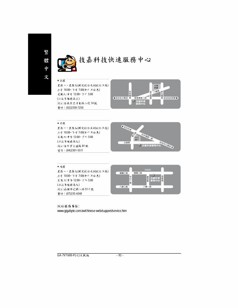
�
~ ( )
10:00~ 7:00( )
: 12:00~ 5:00
( )
: 14
(02)2358-7250
�
~ ( )
10:00~ 7:00( )
: 12:00~ 5:00
( )
: 81
(04)2301-5511
�
~ ( )
10:00~ 7:00( )
: 12:00~ 5:00
( )
: 51-1
(07)235-4340
:www.gigabyte.com.tw/chinese-web/support/service.htm