agility 3 user manual - securifix 3 full user manual.pdf · solution for your residential and small...
TRANSCRIPT

USER MANUAL
Agility 3 User Manual
Page 2
Important Notice
This guide is delivered subject to the following conditions and restrictions:
This guide contains proprietary information belonging to RISCO Group. Such
information is supplied solely for the purpose of assisting explicitly and properly
authorized users of the system.
No part of its contents may be used for any other purpose, disclosed to any person
or firm, or reproduced by any means, electronic or mechanical, without the
express prior written permission of RISCO Group.
The information contained herein is for the purpose of illustration and reference
only.
Information in this document is subject to change without notice.
Corporate and individual names and data used in examples herein belong to their
respective owners.
All rights reserved.
2013 RISCO Group April 2013

Agility 3 User Manual
Page 3
Table of Contents
Chapter 1 - Introduction ............................................................................................ 5 1.1 Key Features ................................................................................................................................... 5 1.2 Agility Architecture....................................................................................................................... 5 1.3 User Operating Tools .................................................................................................................... 6 1.4 Status Indications .......................................................................................................................... 8
LED Indicators ........................................................................................................................... 8 Status Button / Service Call (Listen & Talk) ............................................................................ 9 Voice Messaging ........................................................................................................................ 9 SMS Messaging .......................................................................................................................... 9 Email Messaging ........................................................................................................................ 9 Sound Indications .................................................................................................................... 10
Chapter 2 - Local System Operation ...................................................................... 11 2.1 Setting your system ..................................................................................................................... 11
Full setting: .......................................................................................................... 11 Part set (Home) setting: ....................................................................................... 12 Partition setting: ................................................................................................... 12 Force Setting:....................................................................................................... 13 Setting with troubles in the system ....................................................................... 13
2.2 Unsetting your system ................................................................................................................ 14 System unsetting: ................................................................................................ 14 Partition unsetting: ............................................................................................... 15 Duress unsetting: ................................................................................................. 15 Unsetting after an alarm: ...................................................................................... 15 Resetting after an alarm: ...................................................................................... 16 Anti Code Reset ................................................................................................... 16 Engineer Reset .................................................................................................... 16
2.3 Sending a Panic Alarm ................................................................................................................ 17 Chapter 3 - Remote System Operation .................................................................. 19
3.1 Remote Phone Operation............................................................................................................ 19 Remotely Accessing the System ............................................................................................. 19 Voice Operations Menu .......................................................................................................... 19 Receiving Calls from the System ............................................................................................ 20 Acknowledge Menu ................................................................................................................ 21 Bi-directional Communication ............................................................................................... 21
3.2 SMS Operation ............................................................................................................................. 22 SMS Remote Control ............................................................................................................... 22 SMS Confirmation Message .................................................................................................... 23
3.3 Smartphone / Web Operation .................................................................................................... 23 Downloading the App ............................................................................................................. 23 Self registration ........................................................................................................................ 23 Smartphone Operations .......................................................................................................... 24 Smartphone Operations .......................................................................................................... 24

Agility 3 User Manual
Page 4
Chapter 4 - User Functions and Settings .............................................................. 25 4.1 User Codes ................................................................................................................................... 25 4.2 Proximity Tags ............................................................................................................................. 27 4.3 Defining Follow Me Destinations .............................................................................................. 28 4.4 Scheduler ...................................................................................................................................... 29 4.5 Macro keys ................................................................................................................................... 30 4.6 Complete Menu of User Functions ............................................................................................ 31
Chapter 5 - System Specifications ......................................................................... 34 Chapter 6 - EN 50131 Compliance.......................................................................... 35 Appendix A - Keypad User Operations .................................................................. 36
Common Operations ......................................................................................................................... 36 Advanced Operations ....................................................................................................................... 36 LEDs Indication ................................................................................................................................. 38
Appendix B - Remote Control User Operations .................................................... 39 Common Operations ......................................................................................................................... 39 Advanced Operations ....................................................................................................................... 39 Status LED/Buzzer Indications ........................................................................................................ 40 Changing Remote Control PIN Code ............................................................................................. 40
Appendix C - Engineer Event Log Messages ........................................................ 41 Appendix D: Web User Application ....................................................................... 46
Logging In .......................................................................................................................................... 46 The Main Page ................................................................................................................................... 46 Setting and Unsetting via the Web Application ............................................................................ 48

Agility 3 User Manual
Page 5
Chapter 1 - Introduction
Congratulations on your purchase of Agility 3- RISCO Group's Picture Perfect Wireless
Security System. RISCO Group’s Agility 3 elegantly combines state-of-the-art video
verification and Smartphone apps with advanced wireless security and safety features.
Alarm Receiving Centres can now identify false alarms, as video verification enables
immediate confirmation of a crime-in-progress, prioritizing response, increasing efficiency,
and giving you on-the-go control and monitoring of your home security.
Featuring remote management, advanced communication, simple installation, and a
comprehensive range of peripherals, Agility 3 with video verification is the ideal wireless
solution for your residential and small commercial requirements.
This manual describes how to operate your system. It will guide you through
programming instructions for main system features as well as basic setting and unsetting
commands for the system.
1.1 Key Features
Up to 32 wireless zones (1 way or 2
way wireless detectors) + 4 optional
wired zones (with I/O expander)
31 User codes + Grand Master code
5 fixed authority levels for user
Proximity tag for each user
3 partitions
3 wireless keypads (LCD or LED)
3 wireless sounders (internal or
external)
8 rolling code keyfobs
16 Follow Me destinations
4 outputs (I/O expander)
2-way listen-in and talk
X-10 support
250 Events Log
Up to 8 PIR Cameras for video verification
Smartphone operation of principal functions
Full voice-guided menu for remote system operation
1.2 Agility Architecture
Your Agility controls and monitors a variety of sensors, detectors, and contacts
placed throughout the premises, which provide external, perimeter and internal
burglary protection. The system is supervised, meaning that the panel checks the

Agility 3 User Manual
Page 6
status of each sensor to detect problems. If the panel detects trouble it will notify
you with beeps and indicator lights on the panel itself.
The following diagram shows the components that make up the system:
1.3 User Operating Tools
The Agility system can be operated using several devices, some of which have been
designed as bi-directional. If you have purchased a bi-directional device, your system is
capable of sending a return reply status indication from the panel to the device for each
command that is sent to it.
Depending on your purchase you can operate your system via the following:
Smartphone Operations:
Homeowners can now enjoy the iRISCO Smartphone App for
smart and easy control of their Agility system. The app enables
users to set/unset the system on-the-go, visually verify alarms by
viewing images taken by their PIR Cameras, take snapshots,
activate home automation devices, omit detectors, view the
system’s status and history, and much more. Available for
iPhone, iPad and Android.
Agility 3 User Manual
Page 7
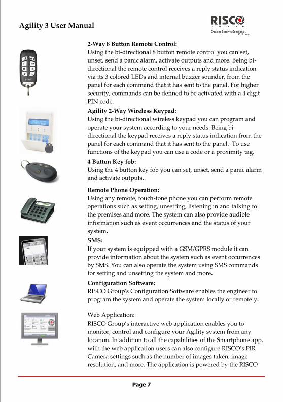
2-Way 8 Button Remote Control:
Using the bi-directional 8 button remote control you can set,
unset, send a panic alarm, activate outputs and more. Being bi-
directional the remote control receives a reply status indication
via its 3 colored LEDs and internal buzzer sounder, from the
panel for each command that it has sent to the panel. For higher
security, commands can be defined to be activated with a 4 digit
PIN code.
Agility 2-Way Wireless Keypad:
Using the bi-directional wireless keypad you can program and
operate your system according to your needs. Being bi-
directional the keypad receives a reply status indication from the
panel for each command that it has sent to the panel. To use
functions of the keypad you can use a code or a proximity tag.
4 Button Key fob:
Using the 4 button key fob you can set, unset, send a panic alarm
and activate outputs.
Remote Phone Operation:
Using any remote, touch-tone phone you can perform remote
operations such as setting, unsetting, listening in and talking to
the premises and more. The system can also provide audible
information such as event occurrences and the status of your
system.
SMS:
If your system is equipped with a GSM/GPRS module it can
provide information about the system such as event occurrences
by SMS. You can also operate the system using SMS commands
for setting and unsetting the system and more.
Configuration Software:
RISCO Group's Configuration Software enables the engineer to
program the system and operate the system locally or remotely.
Web Application:
RISCO Group’s interactive web application enables you to
monitor, control and configure your Agility system from any
location. In addition to all the capabilities of the Smartphone app,
with the web application users can also configure RISCO’s PIR
Camera settings such as the number of images taken, image
resolution, and more. The application is powered by the RISCO

Agility 3 User Manual
Page 8
Cloud server.
1.4 Status Indications
LED Indicators
The LED indicators provide typical system indications, as discussed
below. Some indicators have additional functions, which are explained
later on.
Power LED (Green)
The Power LED indicates system operation.
Condition Description
On Power OK
Rapid flash Indicates AC fault
Slow flash Indicates low battery fault
Set/Alarm LED (Red)
Condition Description
On System Set
Rapid flash Alarm
Slow flash System in Exit delay
Part set LED (Red)
Condition Description
On System armed at PART SET
Off System Unset
Ready LED (Green)
Condition Description
On System Ready
Off Open zones
Slow Flash System is ready to be set while a specially
designated entry/exit door remains open
Fault LED (Amber)
Condition Description
Rapid Flash Fault
Off No fault
Note: When all LEDs flash one after another in sequence the system is in Learning mode.
Agility 3 User Manual
Page 9
Status Button / Service Call (Listen & Talk)
The button on the main unit can be defined as a system status indicator or as a S.O.S
button. Once pressed, a service call can be established to the alarm receiving centre,
which then enables 2-way communication with the premises.
Voice Messaging
Three types of spoken messages are heard when using the Agility, locally in the
premises or remotely to your mobile:
Event messages: Upon selected event occurrence, the Agility initiates a call to a
remote Follow Me (FM) telephone number, informing you of a security situation by
playing a pre-recorded Event announcement message.
Status messages: Upon remote access of the system by initiating a call from a
remote telephone or receiving a call from the system, the Agility announces the
current system status by playing a pre-recorded Status message.
Local Announcement messages: Upon event occurrence or user’s keypad
operations, the Agility can announce various local messages to residents.
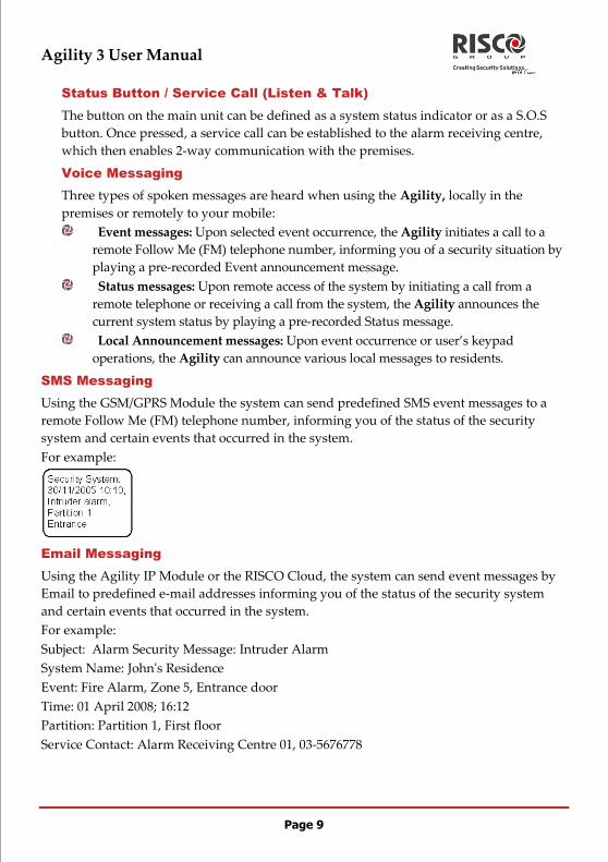
SMS Messaging
Using the GSM/GPRS Module the system can send predefined SMS event messages to a
remote Follow Me (FM) telephone number, informing you of the status of the security
system and certain events that occurred in the system.
For example:
Email Messaging
Using the Agility IP Module or the RISCO Cloud, the system can send event messages by
Email to predefined e-mail addresses informing you of the status of the security system
and certain events that occurred in the system.
For example:
Subject: Alarm Security Message: Intruder Alarm
System Name: John's Residence
Event: Fire Alarm, Zone 5, Entrance door
Time: 01 April 2008; 16:12
Partition: Partition 1, First floor
Service Contact: Alarm Receiving Centre 01, 03-5676778
Agility 3 User Manual
Page 10
Sound Indications
In addition to the visual indications provided by the Agility’s LEDs, your system produces
audible notification after certain events.
Condition Description
Intrusion alarm Continues rapid beeping
Fire alarm Staggered rapid beeping
Exit delay Slow buzzer beeps until the Exit Delay time period
expires
Entry delay Slow buzzer beeps until the Entry Delay time period
expires.
Confirm operation A one-second tone
Reject operation Three rapid error beeps
Set/Unset squawk 1 sounder chirp: System Full Set
2 sounder chirps: System is Unset
4 sounder chirps: System Unset after an alarm

Agility 3 User Manual
Page 11
Chapter 2 - Local System Operation
2.1 Setting your system
Setting your system causes the intrusion detectors to trigger an alarm when violated. The
setting operation will be followed by a local message announcement (if defined).
Before setting the system check the Ready LED and make sure that the system is ready
to be set. If the system is NOT ready to be set, secure or omit the violated zone(s), and then
proceed.
Failing to set the system will be indicated by the system
Your Agility offers the following kinds of setting:
Note: If you are unable to set the system, press the status key to view system messages.
Full setting:
Full setting prepares all of the system's intrusion detectors to activate an alarm if
violated, and is used when leaving the premises. The system will set after the
designated countdown time (Exit delay) and a local message will sound. Once you have
set the system, exit via the designated final exit door.
To set using Full setting procedure
Quick mode:
High security mode: Press + code
Quick mode:
High security mode: + code or proximity tag
Press
Send SMS : [Code][S], example, 1234S

Agility 3 User Manual
Page 12
Click Full Set
Part set (Home) setting:
Part set setting activates only perimeter detectors (as defined by your engineer),
enabling individuals to remain inside and move about the premises while the system is
partially set.
To set using Part set (Home) setting procedure
Quick mode:
High security mode: + code
Quick mode:
High security mode: + code or proximity tag
Press button or button 4 (if defined. Advise with your engineer)
Send SMS : [Code][P], example, 1234P
Click Part Set
Partition setting:
One of the Agility's advantages is its ability to divide the system in up to 3 partitions.
Each partition may be managed as a separate security system, each of which can be set
and unset individually regardless of the condition of the other.
Partitions can be set or unset one at a time, or all at once, and each partition can be set at
Part set or Full set. Only users that have been defined to operate multiple partitions can
operate more than one partition and set/unset all partitions at once
Agility 3 User Manual
Page 13
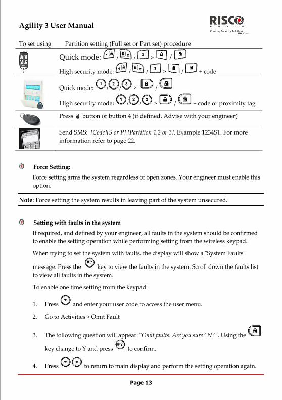
To set using Partition setting (Full set or Part set) procedure
Quick mode: / / > /
High security mode: / / > / + code
Quick mode: / / > /
High security mode: / / > / + code or proximity tag
Press button or button 4 (if defined. Advise with your engineer)
Send SMS: [Code][S or P] [Partition 1,2 or 3]. Example 1234S1. For more
information refer to page 22.
Force Setting:
Force setting arms the system regardless of open zones. Your engineer must enable this
option.
Note: Force setting the system results in leaving part of the system unsecured.
Setting with faults in the system
If required, and defined by your engineer, all faults in the system should be confirmed
to enable the setting operation while performing setting from the wireless keypad.
When trying to set the system with faults, the display will show a "System Faults"
message. Press the key to view the faults in the system. Scroll down the faults list
to view all faults in the system.
To enable one time setting from the keypad:
1. Press and enter your user code to access the user menu.
2. Go to Activities > Omit Fault
3. The following question will appear: "Omit faults. Are you sure? N?". Using the
key change to Y and press to confirm.
4. Press to return to main display and perform the setting operation again.

Agility 3 User Manual
Page 14
2.2 Unsetting your system
Unsetting your system causes the detectors not to trigger an alarm when violated. When
you enter the premises, the Entry Delay begins to count down. You must unset the system
within the Entry Delay time to prevent the system from triggering an alarm. The unsetting
operation will be followed by a local message announcement (if defined).
Note: If an alarm occurred in the system, it is recommended to leave the premises. Only
after police investigation should you consider that the intruder is no longer on
your premises and you can re-enter. In special cases (if programmed by your
engineer) setting the system after an alarm might require an Engineer code. For
more information refer to your engineer
Your Agility offers the following kinds of unsetting:
System unsetting:
Unsetting deactivates the partitions assigned to the specified user code
To unset using Procedure for Unsetting
Quick mode: . All partitions assigned to the button will be unset
High security mode: > Code
Press followed by code or proximity tag.
Press the button. All partitions assigned to the button will be
unset.
Send SMS: [Code][U], example 1234U

Agility 3 User Manual
Page 15
Enter your user code and click UNSET
Partition unsetting:
Partition unsetting enables you to unset individual partitions within a set system
To unset using Procedure for Partition Unsetting
Quick mode: / / >
High security mode: / / > > Code
/ / > > code or proximity tag.
Press the button. All partitions assigned to the button will be
unset.
Send SMS: [Code][U] [Partition 1,2 or 3]. Example 1234U1. For more
information refer to page 22.
Duress unsetting:
If you are ever coerced into unsetting your system, you can comply with the intruder's
wishes while sending a silent duress alarm to the Alarm Receiving Centre. To do so,
you must use a special duress code, which when used, will unset the system in the
regular manner, while simultaneously transmitting the duress alarm. Confer with your
engineer which of the user's codes is defined as a duress code.
Note: Under no circumstances must the duress code be used haphazardly or without
reason. Alarm Receiving Centres, along with Police Departments, treat duress
codes very seriously and take immediate action.
Unsetting after an alarm:
When silencing an alarm the system goes into a unset state. After the system is unset the
sounders will sound 4 sounder chirps indicated that an alarm occurred in the system. On
the keypad, press for 2 seconds in order to view information about the last alarm.

Agility 3 User Manual
Page 16
If an "Entry door" is opened prior to unsetting the system, the following voice
announcement message will be heard: "Alarm occurred in the system". Press the
key will indicate the cause of the alarm.
Note: If an alarm occurred in the system, it is recommended to leave the premises.
Only after police investigation should you consider that the intruder is no
longer on your premises and you can re-enter. In special cases (if programmed
by your engineer) setting the system after an alarm might require an engineer
code. For more information refer to your engineer.
Note: Your engineer can define the number of times (0-15) that an alarm will be sent
from the same detector during one setting period. This is usually used to
prevent an alarm from a malfunction detector, an environmental problem or
incorrect installation
Resetting after an alarm:
Your installation company can define that the reset of the system to a Normal Operation
mode will require the intervention of your alarm receiving centre or engineer. In this
case, after an alarm condition the system will be regarded as Not Ready and while
requesting for system status ( ) indication you will get a fault message: Engineer
Reset.
Anti Code Reset
Press .
Enter user code
Go to Activities > Anti Code option.
Call your alarm receiving centre (ARC) or engineer and quote the
“RANDOM CODE” displayed on your keypad. The ARC or engineer will
give you a return Anti-Code.
Enter this Anti code followed by and the system will reset.
Engineer Reset
Your alarm receiving centre (ARC) or engineer can reset your system remotely or
locally from the keypad.

Agility 3 User Manual
Page 17
To enable local reset by your engineer you may need to authorize him/her using the
master code after the engineer enters his/her code. A one hour time window is
opened for the engineer to program user functions and be able to reset your system
locally
2.3 Sending a Panic Alarm
Panic alarms enable you to send a message to the alarm receiving centre in the event of an
emergency, send a message to a follow me number, announce a local message or activate a
local alarm. Panic alarms can be set to be silent (Refer to your engineer for more
information).
To send a Panic
Alarm using
Procedure
Press both and keys simultaneously
Press both and keys simultaneously
Note: Your engineer should define these keys to be set as panic
keys. These keys can be either disabled or used to
establish a service call to your Alarm Receiving Centre.
If defined by your engineer pressing
simultaneously for 2 seconds will send a fire alarm and
pressing simultaneously for 2 seconds will
send a special emergency or medical alarm.
Press the small blank button (if defined)
Note: Your engineer can define the small blank button to be used
for sending a panic alarm.
Note: For full capabilities of the 2-way remote control, the bi-directional keypad and 4
button key fob, refer to the instructions supplied with each product.
Press both keys simultaneously

Agility 3 User Manual
Page 18
Press the panic button
Agility 3 User Manual
Page 19
Chapter 3 - Remote System Operation
3.1 Remote Phone Operation
The Agility enables you to operate the system from a remote touch-tone phone by
initiating a telephone call to or from the system and interacting with voice menus that
guide you through your required remote operation.
Remotely Accessing the System
Remotely accessing the system involves initiating a call to the system, and entering your
remote access code and the user code you usually enter in the system keypad.
To remotely access the system:
1. From a remote touch-tone telephone, dial the number of the premises where
Agility is installed.
2. If your system is connected to a land telephone line and an answering machine
is in use at the premises let the line ring once, then hang up, wait 20 seconds and
call again.
3. If an answering machine is not in use at the premises wait until the system
picks up. After the system picks up a short tone is heard.
Note: When the system picks up, all phones on the same line are effectively
disconnected and cannot be used (depending on engineer wiring).
4. Enter your 2 digit remote access code within 5 seconds (Default code = 00). The
following message is announced: "Hello, Please Enter Your User Code, Followed
By [#]".
Enter your user code followed by [#]. (Default code=1234)
5. After your code is accepted a system status message is announced, followed by
the Operations menu. You can now perform the required remote operations.
Voice Operations Menu
The Voice Operations menu announces options and instructions on how to use the system
functions. The options in the Operations menu vary according to system status and your
access rights.
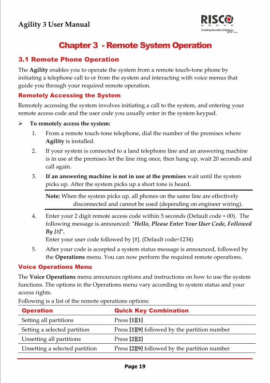
Following is a list of the remote operations options:
Operation Quick Key Combination
Setting all partitions Press [1][1]
Setting a selected partition Press [1][9] followed by the partition number
Unsetting all partitions Press [2][2]
Unsetting a selected partition Press [2][9] followed by the partition number

Agility 3 User Manual
Page 20
Operation Quick Key Combination
Changing Zone Omit status Press [3] followed by the zone number and then [#][9]
Operating Programmable
outputs
Press [4] followed by the output number
Changing Follow Me(FM)
numbers
Press [5] followed by the FM number and [#][2].
Enter the new phone number and press [#][1].
Listen in to the premises Press [6][1]
Talking to the premises Press [6][2]
Listen and Talk to the premises Press [6][3]
Recording messages that are not
included in the message bank (5
messages)
Press [7][1]… [5]
Recording an opening message Press [7][6]
Exiting the System Press [0]
To return to the previous menu Press [*]
To repeat the menu options Press [#]
Receiving Calls from the System
Upon event occurrence, such as alarm activation, the system informs you of security
situations, for example, intrusion or fire, by calling you and announcing a pre-recorded
event announcement message, followed by the Acknowledge menu. The system can call
up to 16 Follow Me numbers, enabling you, a relative or neighbour to be informed of the
security situation. You can then take the appropriate action, whether this is to inform the
authorities or acknowledge the event and remotely operate the system.
Notes: Follow Me messages are performed only after reporting to the Alarm Receiving
Centre.
Follow Me numbers are assigned certain events for which they receive calls.
The system must be programmed to call a FM number after a specific event
occurs in order for that event to trigger the call.
To receive an event call:
1. Pick up the phone.
2. Say "Hello" or press [#]. The Event Announcement message is made, informing
you of a security situation in your system, for example:
“24 Oaklands Street, Intruder alarm, Ground Floor, kitchen”

Agility 3 User Manual
Page 21
Notes: If no voice is detected, the event message will start playing 5 seconds after phone
pick up. Press [#] to begin playback of the event message from the beginning.
To repeat the Event Announcement message press [#].
To omit the Event Announcement message and go directly to the Acknowledge
menu, press [*].
3. Acknowledge the event. (See Acknowledge Menu)
Acknowledge Menu
After the Event Announcement message is made, the following list of options is
announced:
Operation Digit
Acknowledge Message
Acknowledging an event means that you have received a message from
the security alarm system about a relevant event in the system and
want to confirm this. After you acknowledge an event, the system calls
the next FM number.
Press [1]
Acknowledge and stop all dialing
This option acknowledges the event and stops the system from calling
the next FM numbers to report the event.
Press [2]
followed by
the code
Acknowledge and access the Operations menu
The Operations menu lists the available options for remotely operating
your system.
Press [3]
followed by
the code
Listen In and Talk
This option enables you to perform bi-directional communication.
Press [6]
followed by
the code
Repeat the event message Press [#]
Repeat the Acknowledge menu Press [*]
Note: If an invalid code is entered 3 consecutive times, the system hangs up and this FM
number is locked for 15 minutes and no calls are initiated to the FM number.
If a valid user code is not entered within 10 seconds, the system hangs up.
Bi-directional Communication
The Listen In and Talk options enable you to remotely and silently listen in to your
premises in order to verify the cause of an event occurrence, through the microphone or
remotely talk to your premises via the Agility loudspeaker, for example, to guide someone
in distress.

Agility 3 User Manual
Page 22
To listen in or talk:
1. From the Operations/Acknowledge menu, press [6]. The following messages are
announced:
“To Listen In press 1, To Talk press [2], To Listen and Talk (Open channel) press
[3], To return to the previous menu, Press [].”
2. Select the desired option.
3. Press [] to end listening in and talking communication and return to the
Operations menu.
Bi-directional Audio Options after an Alarm
In the event of Burglary, Fire and Medical alarms, the Agility is able to report these events
and then stay on the line. This allows the Alarm Receiving Centre to perform Voice Alarm
verification, verify the alarm or Verification in order to verify a cause of event or guide
someone in distress.
Service call
The Service Call feature enables you to call the Alarm Receiving Centre by pressing a key.
To establish the service call, press the button on the main unit or press simultaneously the
buttons on the bi-directional keypad.
Note: The Service call should be defined by your engineer.
3.2 SMS Operation
SMS Remote Control
The Agility enables you to perform remote control operations using simple SMS
commands. The following section describes the SMS commands and the response of the
system to these commands.
Note: This application is available only if a GSM/GPRS module is installed in your system.
Operation SMS Message Structure Example
Set all partitions of
a user code
[Code] S 1234S
Set all partitions to
Part set/Home
Setting
[Code] P 1234P
Unset all partitions
of a user code
[Code] U 1234U
Set by partition [Code] S [Partition No.] 1234S1
Part set by partition [Code] P [Partition No.] 1234P1

Agility 3 User Manual
Page 23
Operation SMS Message Structure Example
Unset by Partition [Code] U [Partition No.] 1234U1
Omit a zone [Code] OM [zone number] 1234OM05
Un-omit a zone [Code] UNOM [zone No.] 1234UNOM05
Activate Output [Code] POON [PO No.] 1234POON1
Deactivate Output [Code] POOFF [PO No.] 1234POOFF1
Change FM
number
[Code] FMPHONE [FM serial number]
NEW [New Phone No.)
1234FMPHONE 3
NEW0529692345
Get system status [Code] ST 1234ST
Get last alarm
memory
[Code] AL 1234AL
Get SIM credit level
(for prepaid cards)
[Code] CR 1234CR
Notes: SMS commands can be sent from any mobile phone or from an SMS website.
Command words are not case sensitive.
A separator between command words is not required although it is accepted.
SMS Confirmation Message
A confirmation message following a SMS operation is sent to the user, upon request, by
adding the letters “RP” at the end of the SMS messages listed below.
Example:
1234 S RP - A confirmation message following an setting operation will be sent to the user.
Confirmation or Fail operation messages can be assigned to the actions of setting,
unsetting, omitting, activating outputs or changing follow me definitions.
3.3 Smartphone / Web Operation
Agility 3 is smartphone and web-friendly.
Downloading the App
The smartphone app can be downloaded from the Apple App store under the iRISCO
name or from Android play store .
Self registration
To enable the use of the iRISCO App, register your panel to the RISCO cloud.
Note: If using GPRS verify with your engineer that your panel is set to GPRS
communication

Agility 3 User Manual
Page 24
1. Navigate your browser to www.riscocloud.com/register
2. Enter your details in the form.
3. In the Panel ID field copy the 15 digits of the panel from the label located on the
side of the panel or as printed on the postcard that arrived with the panel.
Once defined you will be able to use your app or the web from www.riscocloud.com . Use
login (email address) and password as defined during the registration process. The
passcode is the user code for your alarm system.
Smartphone Operations
The following list describes the actions you can perform from the smartpone application:
Full Set
Part Set
Full Unset
Omit zones
Take image upon request
View history images taken upon alarm event
View history events
Turn ON/OFF Outputs
Set followers for email notification
Once defined you will be able to use your app. Use login and password as defined during
the registration process. The passcode is the user code you use in your alarm system.
Agility 3 User Manual
Page 25
Chapter 4 - User Functions and Settings
The functions and settings explained in this chapter can only be performed via your LCD
keypad and the Configuration Software. This chapter refers to these functions and settings
as performed via the LCD keypad. Refer to the Configuration Software manual for more
information regarding how these functions and settings are performed via the
Configuration Software.
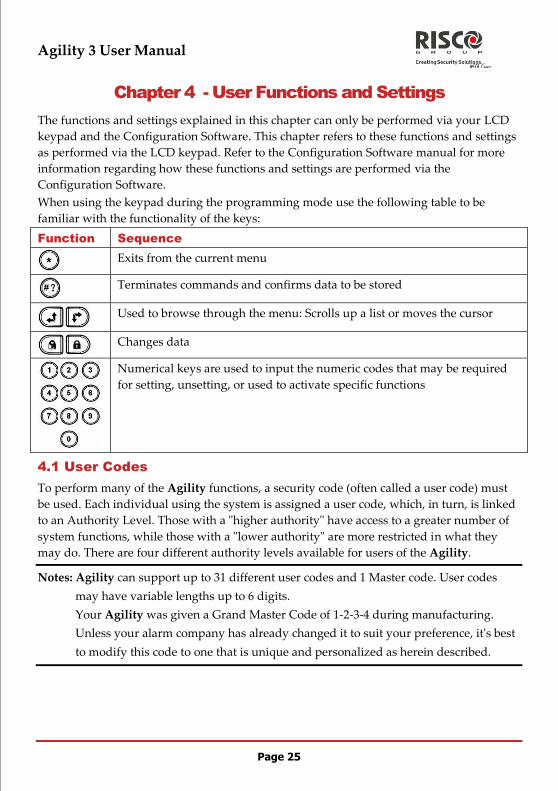
When using the keypad during the programming mode use the following table to be
familiar with the functionality of the keys:
Function Sequence
Exits from the current menu
Terminates commands and confirms data to be stored
Used to browse through the menu: Scrolls up a list or moves the cursor
Changes data
Numerical keys are used to input the numeric codes that may be required
for setting, unsetting, or used to activate specific functions
4.1 User Codes
To perform many of the Agility functions, a security code (often called a user code) must
be used. Each individual using the system is assigned a user code, which, in turn, is linked
to an Authority Level. Those with a "higher authority" have access to a greater number of
system functions, while those with a "lower authority" are more restricted in what they
may do. There are four different authority levels available for users of the Agility.
Notes: Agility can support up to 31 different user codes and 1 Master code. User codes
may have variable lengths up to 6 digits.
Your Agility was given a Grand Master Code of 1-2-3-4 during manufacturing.
Unless your alarm company has already changed it to suit your preference, it's best
to modify this code to one that is unique and personalized as herein described.

Agility 3 User Manual
Page 26
Setting / Changing User Codes
The user assigned the Grand Master authority level can change all user codes but cannot
view the digits in the user code fields. Users with other authority levels can only change
their own codes. The system must be unset in order to set or change user codes.
Note: User codes can also be defined from the web application
To set/change a user code:
1. Press and
2. Enter your code
3. Using the arrow keys, scroll to the option Codes/Tags and press .
Note: If you enter a wrong user code, the keypad produces 3 short beeps and the "Wrong
Code. Please Try Again" message will be heard. Press quickly and re-enter
the above sequence correctly.
4. Scroll to Access Codes and press .
5. You will see the option New/Change. Press
6. Using the arrows scroll to select the User Index number to which you want to
assign a user code and press .
Note: In the Agility system, the User Index number is from 00 to 31, where 00 belongs to
the Grand Master.
7. Enter the new code and then re-enter the code. If successful, a single
confirmation beep is sounded, if not, 3 quick error beeps are sounded
8. Repeat the above steps for additional codes until you have completed your list
Deleting User Codes
At times, you may want to completely delete a user code. Note that it is impossible to
delete the Master Code (although it can be changed).
The system must be unset in order to delete user codes.
To delete a user code:
1. Follow steps 1-4 of the previous procedure (See Setting/Changing User Codes)
2. Scroll the menu to the option "Delete Code". Press
3. Using the arrows scroll to select the User Index number which you want to
delete and press .

Agility 3 User Manual
Page 27
4. The display will show: "Delete User. Are you sure?". Use the key to select
[Y] and press . If successful, a single confirmation beep is sounded, if not, 3
quick error beeps are sounded
5. Repeat the above steps for deleting additional codes
4.2 Proximity Tags
The bi-directional keypad enables you to replace the use of a code with a proximity tag to
set and unset the security system or to activate and deactivate home appliances and
utilities, such as heating and lights. Proximity tag programming is performed from the
User Functions menu. When programming a proximity tag, the following three options are
available:
Adding a new tag
Deleting a tag by the user index
Deleting a tag by the user tag
Adding a Proximity Tag
The Grand Master can assign a tag to any user in the system. Each proximity tag can be
assigned to only one user.
To add a proximity tag:
1. Press
2. Enter your user code
3. Using the arrow keys scroll to the option Codes/Tags from the User Functions
menu and press
4. Scroll to Proximity Tags and press .
5. Select the option New/Change. Press .
6. Using the arrows scroll to select the User Index number to which you want to
assign a tag and press .
7. Within 10 seconds, hold the proximity tag at a distance of 1 to 2 cm. from the
keypad’s keys. The keypad automatically reads the proximity tag and saves it into
the system’s memory. Once the proximity tag has been successfully recorded, a
long confirmation beep sounds, and a confirmation message is displayed. If the
proximity tag is already stored in the system’s memory, 3 error beeps will sound
and a reject message will appear.
Agility 3 User Manual
Page 28
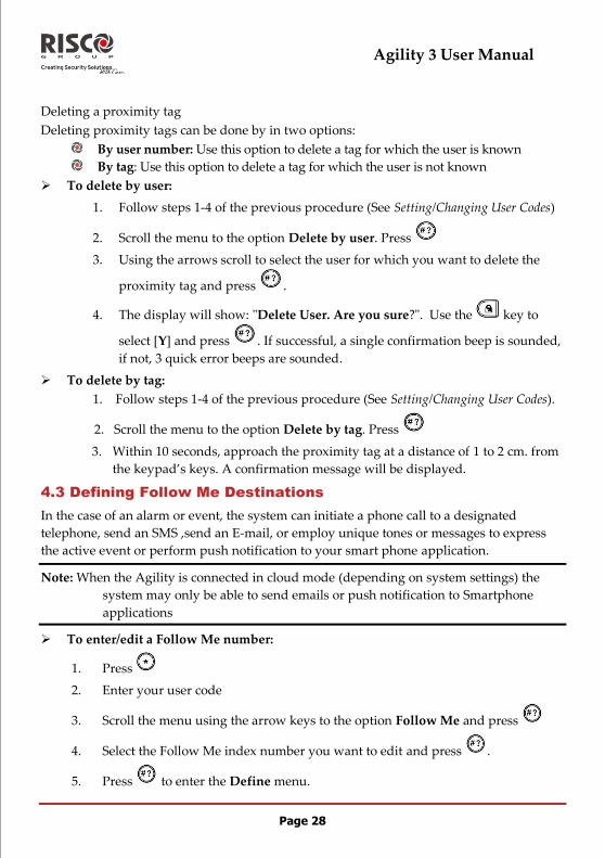
Deleting a proximity tag
Deleting proximity tags can be done by in two options:
By user number: Use this option to delete a tag for which the user is known
By tag: Use this option to delete a tag for which the user is not known
To delete by user:
1. Follow steps 1-4 of the previous procedure (See Setting/Changing User Codes)
2. Scroll the menu to the option Delete by user. Press
3. Using the arrows scroll to select the user for which you want to delete the
proximity tag and press .
4. The display will show: "Delete User. Are you sure?". Use the key to
select [Y] and press . If successful, a single confirmation beep is sounded,
if not, 3 quick error beeps are sounded.
To delete by tag:
1. Follow steps 1-4 of the previous procedure (See Setting/Changing User Codes).
2. Scroll the menu to the option Delete by tag. Press
3. Within 10 seconds, approach the proximity tag at a distance of 1 to 2 cm. from
the keypad’s keys. A confirmation message will be displayed.
4.3 Defining Follow Me Destinations
In the case of an alarm or event, the system can initiate a phone call to a designated
telephone, send an SMS ,send an E-mail, or employ unique tones or messages to express
the active event or perform push notification to your smart phone application.
Note: When the Agility is connected in cloud mode (depending on system settings) the
system may only be able to send emails or push notification to Smartphone
applications
To enter/edit a Follow Me number:
1. Press
2. Enter your user code
3. Scroll the menu using the arrow keys to the option Follow Me and press
4. Select the Follow Me index number you want to edit and press .
5. Press to enter the Define menu.

Agility 3 User Manual
Page 29
6. Enter the phone number, including the area code (if required) or an e-mail
address, as requested on the screen and press
Up to 32 digits can be included in the phone number.
7. If required, include the special functions described below to achieve the related
effect. You can press the or keys to toggle to the required character.
Function Results
Stop dialing and wait for a new dial tone W
Wait a fixed period before continuing ,
Send the DTMF character
Send the DTMF # character #
Delete numbers from the cursor position simultaneously
8. When done with your complete entry, press to store it.
4.4 Scheduler
The Agility enables you to automate some system operations. This is performed by
defining weekly programs by your engineer. Each program can be defined with up to two
time intervals per day, during which the system automatically performs one of the
following functions:
Automatic Setting/Unsetting: A setting program automatically sets and unsets the
system during your required time intervals.
Automatic PO Activation: A PO (home appliance) activation program
automatically activates and deactivates UOs during your required intervals.
In addition, each program can be defined to be activated in a different manner during
holidays.
Once your engineer defines a schedule program it will be activated.
You have the option to deactivate a program according to your needs.
To disable a weekly program:
1. Press
2. Enter your user code
3. Scroll the menu using the arrow keys to the option Clock and press
4. Press to enter the Scheduler menu.

Agility 3 User Manual
Page 30
5. Select the Scheduling program index number. Use the key to activate /
deactivate and press .
4.5 Macro keys
Programming Macro Keys
Agility enables the engineer or Grand Master to record a series of commands and assign
them to a macro. When the macro is invoked, the recorded commands are executed from
beginning to end. Up to 3 macros can be programmed to a system using the Agility LCD
keypad or the Configuration Software.
Before programming a macro, it is recommended to perform your required series of
commands, making a note of every key you press while doing so.
Notes:
Macros cannot be programmed to perform unsetting commands.
Macro keys are not available in the slim keypad
To program a macro:
1. In the Macro menu select a macro (A, B or C) and press .
2. Enter the sequence of characters according to the following table:
Key Represents
Used to enter numerical characters
Used to move the cursor to the left
Used to move the cursor to the right
Press 1 twice Represents the character
Press 3 twice Represents the character
Press 4 twice Represents the key
Press 6 twice Represents the key
Press 7 twice Represents the character
Press 9 twice Represents the # character

Agility 3 User Manual
Page 31
Key Represents
and 0 simultaneously Deletes your entry from the cursor position forward
/ Use to toggle between / ///#/ and all of the
numeric characters
Used to end the sequence and save it to memory
3. Press to save your entry.
The series of characters is saved and assigned to the selected macro.
For example:
To set partition 1 with the code 1234, enter the following sequence:
1 1 2 3 4
Activating a Macro
Hold 7/8/9 on the keypad for 2 seconds to activate the macro A/B/C respectively. A
confirmation message will be heard:
"[Macro X] activated".
4.6 Complete Menu of User Functions
The Agility comes with a variety of selectable user functions that become available when
you enter the User Functions mode. The following section lists these functions.
Note: Although these functions are in the User Functions menu, you can ask you engineer
to program some of them for you.
To enter the User Functions mode press followed by your user code.
The following table shows full Keypad Operations according to users.
√ - User is able to perform this function
- - User is unable to perform or see this function
Operation Grand
Master
User Engineer
Activities
Omit Zone: Provides the ability to omit any of the
system's intrusion zones.
√ √ -
Omit zone Select zone Define [Y] using the key and press
Main Buzzer On/Off: Used to control the main unit
buzzer.
√ √ √

Agility 3 User Manual
Page 32
Operation Grand
Master
User Engineer
Walk test: Used to easily test and evaluate the operation
of selected zones in your system
√ - √
Output Control: Allows user control of previously
designated external devices (e.g. an appliance, a motor-
driven garage door, etc.)
Output Control Select OutputDefine [Y] using the
key and press
√ √ -
Omit Faults: Used to confirm all faults in the system in
order to enable setting operation.
√ √ -
Anti-code: If defined by your engineer the Agility can be
defined to be not ready to Set after an alarm or tamper
condition. To restore the system to Normal Operation
mode, engineer code or an Anti-code must be entered.
Entering the code supplied by the engineer at this
location will restore the system to the Normal Operation
mode
√ √ -
Advanced Prepaid SIM Check Credit
Use this function to receive information by SMS or Voice
of the credit level in your prepaid SIM card. For more
information refer to your engineer.
√ - -
Advanced Prepaid SIM Reset SIM
After charging a prepaid SIM card, the user has to reset
the SIM Expire Time manually. The time duration for
expiration is defined by your engineer. Not currently
used in the UK.
√ - -
Advanced Restore Alarm: The user must approve an
alarm that occurred in the system. After unsetting an
alarm, an Alarm Memory Display will appear on the
screen.
√ √ -
Advanced Restore Fault: If defined by your engineer,
use this option to reset a fault condition after it has been
corrected.
√ √ -
Advanced Service Mode:: Used to silence an alarm
initiated by any tamper for a Service Time period
specified your engineer. Use this option when replacing
the accessory battery.
√ - √

Agility 3 User Manual
Page 33
Operation Grand
Master
User Engineer
Advanced View IP Address: Use this option to view
the IP address of the Agility.
√ - -
Advanced CS Connect: Enables to establish
communication with the configuration software at a
predefined location through IP or GPRS.
√ - √
Advanced Exit/Entry Beeps: Enables to control the
exit/entry beeps of the current keypad.
√ - √
Follow Me
Define: Used to define Follow Me destinations phone
number or Email address according to its type: Voice
message, SMS or E-mail
√ - √
Test FM: Used to test Follow Me reporting. √ - √
Codes/Tags
Use this menu to set tags and user codes in the system.
For detailed information refer to Chapter 4, page 25.
√ √ -
Clock
Time & Date: Allows the setting of the system time and
date. This definition is required for setting the scheduler
programming in the system.
√ - √
Scheduler: Enables you to activate or deactivate
preprogrammed schedules that were defined by your
engineer. Up to 8 weekly programs can be defined in the
system during which the system automatically sets /
unsets or activates programmable outputs.
√ - √
Event Log
To view a list of system events that have occurred √ - √
Service Information
Allows the display of any previously entered service
information. (Name and phone)
√ √ -
Macro
Enables the engineer or GM to record a series of
commands and assign them to a macro. For more
information refer to section 4.5 Macro keys page 30.
√ - √

Agility 3 User Manual
Page 34
Chapter 5 - System Specifications
The following technical specifications are applicable for the Agility:
Electrical Characteristics
System Power 230VAC (-15%+10%), 50Hz, 50mA
Optional: 9VAC, 50-60Hz
Units Consumptions
Main board: Typical 130mA
GSM: Stand by 35mA, Communication 300mA
Modem: Stand by 20mA, Communication 60mA
IP Card: 90mA (Max)
Backup Battery Sealed Lead Acid Battery 6V 3.2Ah
Battery Dimensions (HxWxD) 67mm x 134mm x 34mm
Internal Sounder intensity 90 dBA @ 1m
Operating Temperature -10C to 40C (14F to 104F)
Storage temperature -20°C to 60°C (-4°F to 140°F)
Physical Characteristics
Dimension (HxWxD) 268.5 mm x 219.5 mm x 64 mm
(10.57 x 8.64 x 2.52 inch)
Weight (Without battery) 1.31Kg (Full configuration)
Wireless Characteristics
RF immunity According to EN 50130-4
Frequency 868.65 MHz
Agility 3 User Manual
Page 35
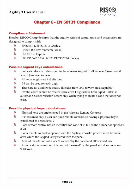
Chapter 6 - EN 50131 Compliance
Compliance Statement
Hereby, RISCO Group declares that the Agility series of central units and accessories are
designed to comply with:
EN50131-1, EN50131-3 Grade 2
EN50130-5 Environmental class II
EN50131-6 Type A
UK: PD 6662:2004, ACPO DD243:2004 (Police)
Possible logical keys calculations:
Logical codes are codes typed in the wireless keypad to allow level 2 (users) and
level 3 (engineer) access
All code lengths are 4 digits long
0-9 can be used for each digit
There are no disallowed codes, all codes from 0001 to 9999 are acceptable
Invalid codes cannot be created since after 4 digits have been typed "Enter" is
automatic. Codes rejection occurs only when trying to create a code that does not
exist.
Possible physical keys calculations:
Physical keys are implemented in the Wireless Remote Controls.
It is assumed only a user can have remote controls, so having a physical key is
considered as access level 2
Each remote control has an identification code of 24 bit, so the number of options is
2^24
For a remote control to operate with the Agility, a "write" process must be made
after which the keypad is registered with the panel.
A valid remote control is one "Learned" by the panel and allows Set/Unset
A non valid remote control is one not "Learned" by the panel and does not allow
Set/Unset

Agility 3 User Manual
Page 36
Appendix A - Keypad User Operations
The following section details the user operations from the 2-way LCD wireless keypad.
User operation can be defined to be activated by a quick mode or high security mode that
requires the use of a code or proximity tag.
In the high security mode the proximity tag can be used as a substitute for inserting a user
code when the display prompts to "Insert a code".
Common Operations
Operation Quick Operation High Security Mode 1
Full Set Press Press followed by code or proximity tag 2
Part Set 3 Press
Press followed by code or proximity tag
Full
Unset
Press followed by code or proximity tag
Consult your engineer for the operations defined with a code
For optimal use of the proximity tag, use it from a distance of 1-2 cm (0.4" - 0.7") from the
center of the keypad's door
For Part set Setting with no entry delay hold the key for two seconds
Advanced Operations
Operation1 Quick Operation High Security Mode
Full Setting Partition
1/2/3
Select partition
/ / and press
Select partition / / and
press followed by code or
proximity tag
Part set Setting
Partition 1/2/3
Select partition
/ / and press
Select partition / / and
press followed by code or
proximity tag
Partition 1/2/3
Unset Select partition / / and press followed by
the code or the proximity tag
Panic alarm / Service
call Press and hold both keys simultaneously 4

Agility 3 User Manual
Page 37
Operation1 Quick Operation High Security Mode
Fire Alarm Press and hold simultaneously for 2 seconds
Emergency/Medical
Alarm Press and hold simultaneously for 2 seconds
System Chime
On/Off Press and hold the button for 2 seconds
Main Unit Speaker
Volume Press and hold the button for 2 seconds
Select the volume level (0=No sound, 4=Full volume)
Press to save your selection
Set keypad LCD
contrast Press and hold for 2 seconds
Use the keys to adjust the keypad's display contrast
and press
Output Control
A/B/C 2
Press and hold button
/ / for 2 seconds
Press and hold button
/ / for 2 seconds
followed by code or proximity tag
View Last Alarm Press and hold button for two seconds
View System Status Short press on : LCD
display
Long press on : LCD
display + voice
Only LCD display : Short press on
followed by code or proximity
tag
LCD display + voice: Long press on
followed by code or proximity
tag
Macro Activation 3 Press and hold / / for 2 seconds
Wake up Keypad Press
Update Keypad
Parameters Press and hold for 2 seconds after changing parameters in
the system
Enter Programming
Mode Press and enter the code

Agility 3 User Manual
Page 38
Operation1 Quick Operation High Security Mode
Changing Keypad
Language Press and hold simultaneously for 2 seconds. Select the
language and press to confirm.
All operations are available while keypad is turned on (Not in Sleep Mode)
Ask your engineer whether outputs control is applicable or not and which output is
assigned to which key
Ask your engineer for the macro defined for each key
Ask your engineer for the keys definition
LEDs Indication
Key Function
(Blue)
Communication with the panel
(Red)
On: Fully or partially set
Slow flash: Exit delay
Rapid flash: Alarm
(Yellow)
Fault in the system during unset mode
Agility 3 User Manual
Page 39
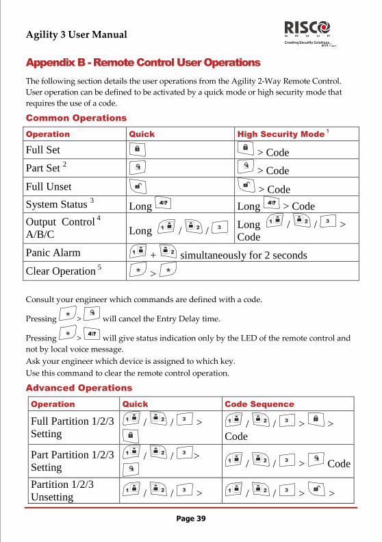
Appendix B - Remote Control User Operations
The following section details the user operations from the Agility 2-Way Remote Control.
User operation can be defined to be activated by a quick mode or high security mode that
requires the use of a code.
Common Operations
Operation Quick High Security Mode 1
Full Set > Code
Part Set 2
> Code
Full Unset > Code
System Status 3 Long
4\?
Long 4\?
> Code
Output Control 4
A/B/C Long / / Long / / >
Code
Panic Alarm + simultaneously for 2 seconds
Clear Operation 5 >
Consult your engineer which commands are defined with a code.
Pressing > will cancel the Entry Delay time.
Pressing > 4\?
will give status indication only by the LED of the remote control and
not by local voice message.
Ask your engineer which device is assigned to which key.
Use this command to clear the remote control operation.
Advanced Operations
Operation Quick Code Sequence
Full Partition 1/2/3
Setting / / >
/ / > >
Code
Part Partition 1/2/3
Setting / / >
/ / > Code
Partition 1/2/3
Unsetting / / > / / > >
Agility 3 User Manual
Page 40
Code
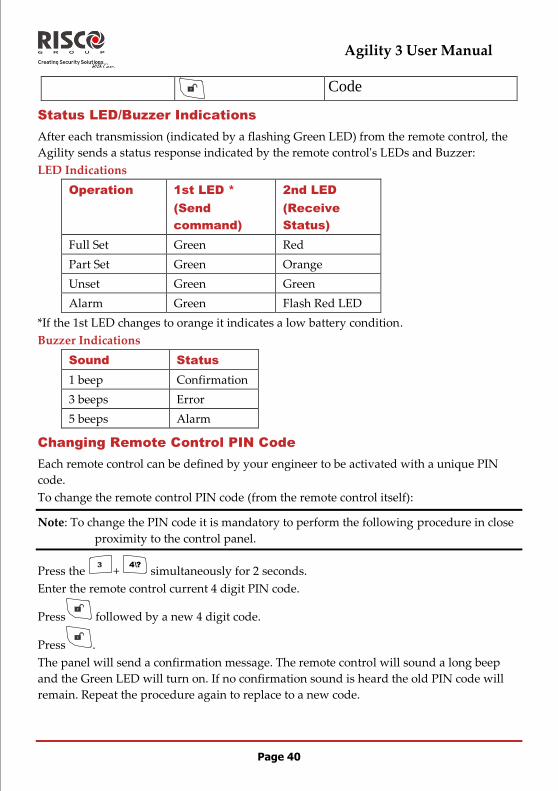
Status LED/Buzzer Indications
After each transmission (indicated by a flashing Green LED) from the remote control, the
Agility sends a status response indicated by the remote control's LEDs and Buzzer:
LED Indications
Operation 1st LED *
(Send
command)
2nd LED
(Receive
Status)
Full Set Green Red
Part Set Green Orange
Unset Green Green
Alarm Green Flash Red LED
*If the 1st LED changes to orange it indicates a low battery condition.
Buzzer Indications
Sound Status
1 beep Confirmation
3 beeps Error
5 beeps Alarm
Changing Remote Control PIN Code
Each remote control can be defined by your engineer to be activated with a unique PIN
code.
To change the remote control PIN code (from the remote control itself):
Note: To change the PIN code it is mandatory to perform the following procedure in close
proximity to the control panel.
Press the + 4\?
simultaneously for 2 seconds.
Enter the remote control current 4 digit PIN code.
Press followed by a new 4 digit code.
Press .
The panel will send a confirmation message. The remote control will sound a long beep
and the Green LED will turn on. If no confirmation sound is heard the old PIN code will
remain. Repeat the procedure again to replace to a new code.

Agility 3 User Manual
Page 41
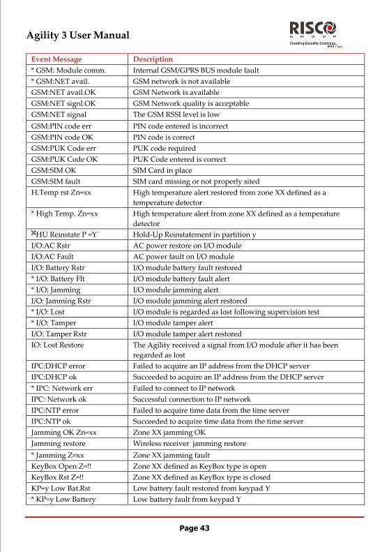
Appendix C - Engineer Event Log Messages
Event Message Description
Activate PO=xx PO XX activation
Actv PO=xx KF=zz PO XX is activated from remote control ZZ AL Reinstate P=y Alarm reinstatement on partition Y
Alarm abort P=y Alarm aborted on partition Y
* Alarm Zone=xx Alarm in zone no. XX
* Anti-code reset Remote reset
Auto Add GSM GSM Module added to the main unit
Auto Add IP card IP Module added to the main unit
Auto Add MODEM Modem added to the main unit
Auto Del GSM GSM Module was removed from the main unit
Auto Del IP card IP Module removed from the main unit
Auto Del MODEM Modem removed from the main unit
Auto test fail Failure of zone self-test
Auto test OK Automatic zone self-test OK
* Set fail P=y Partition Y failed to set
* Set:P=y C=zz Partition Y armed by user no. ZZ
* Set:P=y KF=zz Partition Y armed by remote control ZZ
* Bell tamper Bell tamper alarm
Bell tamper rst Bell tamper alarm restore
* Box tamper Box tamper alarm from main unit
Box tamper rst Box tamper alarm restore
* Omit Box+Bell Box + Bell tamper is omitted
Omit code=xx Omit code XX has been used
* Omit Fault C=xx System faults were omitted by user XX
* Omit Zone=xx Zone no. XX is omitted
Cancel Alarm P=x Cancel alarm event has occurred from partition X. A valid user
function is entered to reset the alarm after the defined Abort alarm
time
Change code=xx Changing user code XX
Change FM=yy Changing Follow-Me number YY
Change tag=xx Changing keypad tag for user XX
Clock not set Time is not set
Clock set C=xx Time defined by user no. XX
Cloud Connected " , Cloud communication channel is functioning
Cloud Disconnect" , // Cloud communication channel is not functioning
CO Alarm Zn=xx CO alert from zone XX defined as a CO detector
CO Rst. Zn=xx CO alert restored from zone XX defined as a CO detector
Com ok IP card Communication OK between the Agility and IP card

Agility 3 User Manual
Page 42
Event Message Description
Comm OK Sounder=y Communication OK between the Agility and Sounder Y
Comm. OK GSM Communication OK between the Agility and GSM
Comm.OK I/O Mdl. Communication OK between the Agility and I/O module
* Conf. alarm P=y Confirmed alarm occurred in partition Y Conf. Hold-Up P=y Confirmed Hold-Up Alarm in partition Y
Confirm rs Z=xx Restore zone confirmed alarm
* Confirm Zone=xx Confirmed alarm occurred from zone XX
CP reset The control panel has reset
Date set C=xx Date defined by user no. XX
* Day Set:P=y Daily set on partition Y
Day unset:P=y Daily unset on partition Y
* Day part set: P=y Daily PART setting in partition Y Device Tmpr Omit Device Tamper Omit
* Unset:P=y C=zz Partition Y unset by user ZZ
* Unset: P=y KF=zz Partition Y unset by remote control ZZ
Duress C=xx Duress alarm from user no. XX
Enter program Entering engineer programming from keypad or configuration
software
Exit Error Zn=xx Exit error event from zone XX
The zone was left open at the end of the exit time
Exit program Exiting engineer programming from keypad or configuration
software
False code False code alarm
False restore False code alarm restore
Fire Keypad=y Fire alarm from wireless keypad Y
Fire main KP Fire alarm from
Fire ok Zone=xx Fault restore in fire zone no. XX
Fire Flt Zn=xx Fault in fire zone no. XX
* Fire Zone=xx Fire alarm in zone no. XX
Foil ok Z=xx Restore in foil (Day) zone no. XX
Foil Zone=xx Fault in foil (Day) zone no. XX
Forced P=y Partition Y is force set
Found Zone=xx Wireless zone found, zone no. XX
* Gas Alarm Zn=xx Gas (natural gas) alert from zone XX defined as a gas detector
Gas Rst. Zn=xx Gas (natural gas) alert restored from zone XX defined as a gas
detector
GSM:IP OK IP connection OK
GSM:IP Fault IP address is incorrect
GSM:Mdl comm.OK Communication between the GSM/GPRS Module and the Agility is
OK
Agility 3 User Manual
Page 43
Event Message Description
* GSM: Module comm. Internal GSM/GPRS BUS module fault
* GSM:NET avail. GSM network is not available
GSM:NET avail.OK GSM Network is available
GSM:NET signl.OK GSM Network quality is acceptable
GSM:NET signal The GSM RSSI level is low
GSM:PIN code err PIN code entered is incorrect
GSM:PIN code OK PIN code is correct
GSM:PUK Code err PUK code required
GSM:PUK Code OK PUK Code entered is correct
GSM:SIM OK SIM Card in place
GSM:SIM fault SIM card missing or not properly sited
H.Temp rst Zn=xx High temperature alert restored from zone XX defined as a
temperature detector
* High Temp. Zn=xx High temperature alert from zone XX defined as a temperature
detector HU Reinstate P =Y Hold-Up Reinstatement in partition y
I/O:AC Rstr AC power restore on I/O module
I/O:AC Fault AC power fault on I/O module
I/O: Battery Rstr I/O module battery fault restored
* I/O: Battery Flt I/O module battery fault alert
* I/O: Jamming I/O module jamming alert
I/O: Jamming Rstr I/O module jamming alert restored
* I/O: Lost I/O module is regarded as lost following supervision test
* I/O: Tamper I/O module tamper alert
I/O: Tamper Rstr I/O module tamper alert restored
IO: Lost Restore The Agility received a signal from I/O module after it has been
regarded as lost
IPC:DHCP error Failed to acquire an IP address from the DHCP server
IPC:DHCP ok Succeeded to acquire an IP address from the DHCP server
* IPC: Network err Failed to connect to IP network
IPC: Network ok Successful connection to IP network
IPC:NTP error Failed to acquire time data from the time server
IPC:NTP ok Succeeded to acquire time data from the time server
Jamming OK Zn=xx Zone XX jamming OK
Jamming restore Wireless receiver jamming restore
* Jamming Z=xx Zone XX jamming fault
KeyBox Open Z=!! Zone XX defined as KeyBox type is open
KeyBox Rst Z=!! Zone XX defined as KeyBox type is closed
KP=y Low Bat.Rst Low battery fault restored from keypad Y
* KP=y Low Battery Low battery fault from keypad Y

Agility 3 User Manual
Page 44
Event Message Description
* Ksw full set:P=y Partition Y is set by key switch
* Ksw unset:P=y Partition Y is unset by key switch
L.bat rstr KF=yy Low battery fault restore from wireless remote control YY
L.Temp rst Zn=xx Low temperature alert restored from zone XX defined as a
temperature detector
* Lost Zone=xx Wireless zone lost, zone no. XX
Low Bat rs Z=xx Low battery fault restored from wireless zone no. XX
Low bat. Zn=xx Low battery fault from wireless zone no. XX
Low bat.KF=yy Low battery fault from wireless remote control XX
* Low Temp. Zn=xx Low temperature alert from zone XX defined as a temperature
detector
Main:AC restore AC power restore on main panel
Main: Battery rst Low battery fault restore from the main panel
Main: Low AC Loss of AC power from the main panel
Main: Low battery Low battery fault from the main panel
* ARC=y call error Communication fail fault to ARC phone no. Y
* ARC=y restore Communication fail fault restore to ARC phone no. Y
* Msg Box Tamper Tamper alarm from the Listen In message box unit
Msg Box Tmp Rst. Tamper alarm restore from the Listen In message box unit
No Com IP card Communication failure between the Agility and IP card
* No comm I/O Mdl. Communication failure between the Agility and I/O module
* No comm Sounder=y Communication failure between the Agility and sounder Y
* No comm. GSM No communication between the GSM/GPRS Module and the Agility
* Phone fail If the phone line is cut or the DC level is under 1V
Phone restore Phone line fault restore
* Police Keypad=y Police (panic) alarm from wireless keypad Y
* Police KF=yy Police (panic) alarm from remote control YY
PTM: Send Data Load new parameters into the Agility from PTM accessory
* Radio l.bat S=y Radio low battery fault from sounder Y
Radio l.bat rS=y Radio low battery restore from sounder Y
* Remote full set:P=y The system has been set from the configuration software
* Remote program The system has been programmed from the configuration software
* Remote part set:P=y The system has been PART Set mode from the configuration
software
Restore Zone=xx Alarm restore in zone no. XX
* RF Jamming Wireless receiver jamming
Rmt unset:P=y Partition Y unset from the configuration software
* Sounder=y Lost Sounder Y is regarded as lost following supervision test
Sounder=y Lost Rst The Agility received a signal from sounder Y after it has been
regarded as lost
Agility 3 User Manual
Page 45
Event Message Description
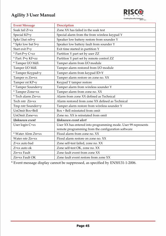
Soak fail Z=xx Zone XX has failed in the soak test
Special KP=y Special alarm from the from wireless keypad Y
Spkr l.bat rsS=y Speaker low battery restore from sounder Y
* Spkr low bat S=y Speaker low battery fault from sounder Y
Start exit P=y Exit time started in partition Y
* Part:P=y C=zz Partition Y part set by user ZZ
* Part: P=y KF=zz Partition Y part set by remote control ZZ
* Tamper I/O Mdl. Tamper alarm from I/O module
Tamper I/O Mdl. Tamper alarm restored from I/O module
* Tamper Keypad=y Tamper alarm from keypad ID=Y
Tamper rs Zn=xx Tamper alarm restore on zone no. XX
Tamper rst KP=y Keypad Y tamper restore
* Tamper Sounder=y Tamper alarm from wireless sounder Y
* Tamper Zone=xx Tamper alarm from zone no. XX
* Tech alarm Zn=xx Alarm from zone XX defined as Technical
Tech rstr Zn=xx Alarm restored from zone XX defined as Technical
Tmp rstr Sounder=y Tamper alarm restore from wireless sounder Y
UnOmit Box+Bell Box + Bell reinstated from omit
UnOmit Zone=xx Zone no. XX is reinstated from omit
Unknown event Unknown event alert
User login C=xx User XX has entered into programming mode. User 99 represents
remote programming from the configuration software
* Water Alrm Zn=xx Flood alarm from zone no. XX
Water rstr Zn=xx Flood alarm restore on zone no. XX
Z=xx auto bad Zone self-test failed, zone no. XX
Z=xx auto ok Zone self-test OK, zone no. XX
Zn=xx Fault Zone fault event from zone XX
Zn=xx Fault OK Zone fault event restore from zone XX
* Event message display cannot be suppressed, as specified by EN50131-1-2006.

Agility 3 User Manual
Page 46
Appendix D: Web User Application
The Web User Application provides a full interface to your system from a PC, cellular
phone or PDA using the WAP portal. Via the Web you can perform a wide range of tasks
such as set/unset, zone omit, user code management and output control. .
Logging In
This application is hosted by your service provider behind a secure firewall.
Access your account through the supplied portal address (default: www.riscocloud.com)
login page.
Enter your Username (email), Password and Pass (PIN) Code: (see Self registration page 23)
alter the interface language as required and then click ENTER.
The Main Page
After logging in, your system’s home page is displayed. The following diagram shows the
home page and explains the main elements of the web application’s interface.

Agility 3 User Manual
Page 47
Menu Bar
Use the Menu Bar to access the set/unset application functionality as per the above
diagram.
The following options are available from the Main Menu:
Home – pressing the Home button allows the user to return to the Main page at
any time
Set/Unset – enables remote system unsetting and (full or partial) setting
Settings – offers various maintenance and management options
including user codes, passwords, alerts, and zone omit.
History – enables you to view the system’s event log (including snapshots)
Video – enables access, activation and configuration of cameras
Outputs – allows you to control and schedule automated lights and appliances in
your home
Help – offers online explanations on how to use the Web Application plus FAQ
and customer support options.
Status Bar
The Status bar displays information on your system’s status and the name of the user
currently logged-in. Above the status bar, the time when the system status display was last
updated is shown. This information is displayed according to the local time at the control
system. To refresh the current system status, click the REFRESH STATUS button on the
right-hand side of the Status bar.
Menu Bar
Status
Bar
Workspace
Home

Agility 3 User Manual
Page 48
Workspace
The workspace offers additional links to the following pages of the application, including:
Users and Codes, History, Alerts, Change Password, Video. When you choose a page,
either from the Main Menu, or from the workspace, the page is displayed in the
workspace. For example, if you choose Set/Unset from the Main Menu, System Operation
area and System Status area are displayed in the workspace (see the figure below).
Home Button
On the main menu, clicking HOME returns you to the Main page.
Setting and Unsetting via the Web Application
Set and unset the system using the System Operation Area buttons or upper-right Set
button (with Full Set/Part Set dropdown).
When using the Web application, the system is set with the programmed delay.
On the Status Bar at page bottom, the current system status is displayed (in our example it
is Disarmed(Unset) and SYSTEM READY, which means that the system and all the
detectors are working properly and an alarm event has been reported).
Use this tab to specify a variety of application parameters
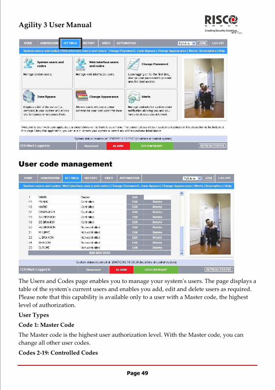
Agility 3 User Manual
Page 49
User code management
The Users and Codes page enables you to manage your system's users. The page displays a
table of the system's current users and enables you add, edit and delete users as required.
Please note that this capability is available only to a user with a Master code, the highest
level of authorization.
User Types
Code 1: Master Code
The Master code is the highest user authorization level. With the Master code, you can
change all other user codes.
Codes 2-19: Controlled Codes

Agility 3 User Manual
Page 50
When you use a controlled user code for setting and unsetting, the system notifies the
monitoring service. You can assign these codes to your children or employees whose
comings and goings are of interest to you.
Codes 20-25: Non-controlled Codes
Non-controlled codes do not cause the system to send Set/Unset reports to the monitoring
service. The system sends an Unset report only if you use this code to unset the system
after an alarm occurrence.
Codes 26-27: Limited Codes
A Limited code is a code that is valid for one day only. This code automatically expires 24
hours after it has been programmed. You can assign a limited code to a visiting guest, for
example.
Code 28: Duress Code
The Duress code is designed for situations where you are being forced to operate the
system. This user code performs the operation selected, while sending a Duress event
message to your monitoring service.
Adding a New User
To add a new user:
1. Click ADD NEW USER at the bottom of the table; the Add New User page
opens.
2. Enter the user's name in the field provided (16 characters max.).
3. Choose the user type from the available options.
4. Enter the new user's 4-digit passcode.
5. Enter the new user's passcode again for confirmation.
6. Enter your Master code.
7. Click Update.
Editing Existing Users
To edit an existing user:
1. Click Edit for the user you want to modify; the Edit User page opens.
2. Edit the user's name in the field provided (16 characters max.). When editing an
existing user, you cannot change the user type.
3. Enter the user's 4-digit passcode.
4. Enter the user's passcode again for confirmation.
5. Enter your Master code.
6. Click Update.

Agility 3 User Manual
Page 51
Deleting a User
To delete a user:
1. Click Delete for the user you want to remove from the table; the confirmation
page opens.
2. Click Yes to confirm.
Web Interface Users and Codes
The Web Interface Users and Codes page provides a useful tool for managing your
system’s users. From this page you can add, edit and delete users as required. You can
even issue temporary (limited) codes to guests that will expire after 24 hours.
On The Main Page menu, click Settings, then Web Interface Users and Codes, the
following page appears:
Master users can click the ADD NEW row to enable creation of a new user, similar to the
process of Self registration:

Agility 3 User Manual
Page 52
Change Password
Click Settings then Change Password to change the password you use to login to the Web
Application.
Zone Omit
On The Main Page menu, click SETTINGS then Zone Omit to omit specified zones in
your home that you don't want to receive event messages from. The Zone Omit page
displays a list of the zones (i.e. sensors) in your system and allows you to omit them or
unomit them as required. An omitted zone is ignored by the system and will not generate
an alarm when triggered. To "unomit" is to restore the zone - effectively instructing the
system to monitor activity from that zone.
All omitted zones are automatically unomitted when the system is disarmed.
Verify Password

Agility 3 User Manual
Page 53
Why would you need to omit a zone?
If a window or door has been left open, the system status will appear as "Not Ready".
Nevertheless, you may want to set the rest of the system and close that window or door
when you arrive home. To do so, you must omit the zone.
To restore a omitted zone to normal operation, you can "unomit" the zone.
Change Appearance
On The Main Page menu, click SETTINGS then Change Appearance to change the color
scheme of your account.

Agility 3 User Manual
Page 54
Alerts
The Alerts feature allows those people included in your contact list to be notified by email
when certain events occur.
To add alert notification recipients to your contact list
1. On the SETTINGS tab, click the Alerts sub-menu to display the following:
2. Click ADD NEW to add email addresses for the alert messages or click Edit to
modify and existing alert recipient
3. In the Name field, enter the name of the contact to receive alerts.
4. In the Email field, enter the email address for email alerts.
5. Alter the Alert Language specification as needed
6. To start receiving the events messages, in the area below, select the checkboxes
according to the event type.
7. Test the alerts you have programmed by clicking the Test button on the Alerts
page near the newly added alert.
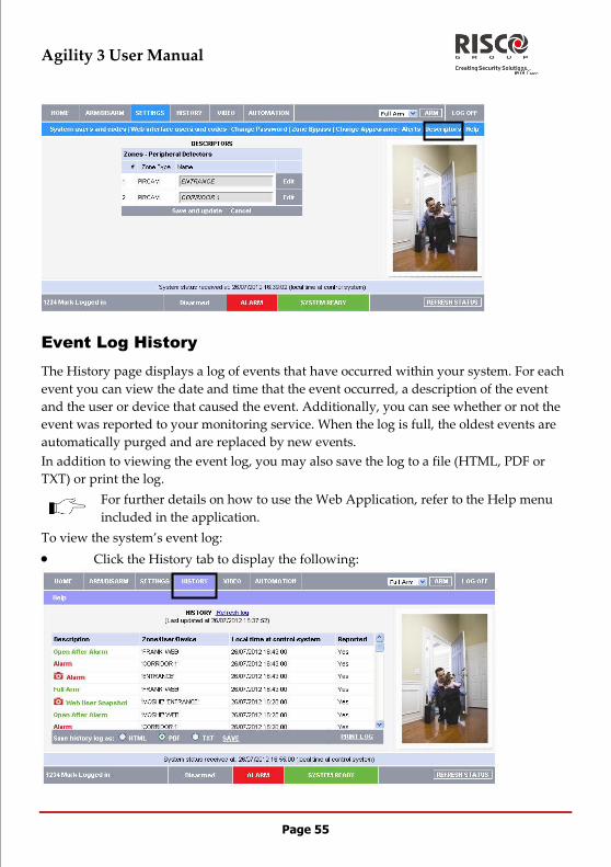
Agility 3 User Manual
Page 55
Event Log History
The History page displays a log of events that have occurred within your system. For each
event you can view the date and time that the event occurred, a description of the event
and the user or device that caused the event. Additionally, you can see whether or not the
event was reported to your monitoring service. When the log is full, the oldest events are
automatically purged and are replaced by new events.
In addition to viewing the event log, you may also save the log to a file (HTML, PDF or
TXT) or print the log.
For further details on how to use the Web Application, refer to the Help menu
included in the application.
To view the system’s event log:
Click the History tab to display the following:

Agility 3 User Manual
Page 56
Video Verification
Using the 2-way wireless video verification PIR detectors installed in your home, the Web
Application enables you to view live images over the Web through the Cameras sub-
menu. Use the Images sub-menu to browse Stored Video Events images.
Use the Settings sub-menu to configure your as follows:
Camera Parameters (Only for 2 Way eyeWAVE PIR Cameras)
Image Resolution QVGA(1) QQVGA (160X120)
QVGA (320X240)
VGA (640X480)
Specifies image size, as defined by pixel resolution.
Image Quality High(1) High/Low
Specifies the extent of jpeg image lossy compression (Low=more compression, smaller
file size; High=less compression, larger file size)
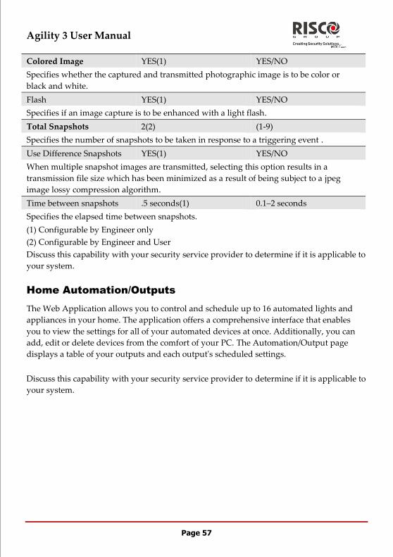
Agility 3 User Manual
Page 57
Colored Image YES(1) YES/NO
Specifies whether the captured and transmitted photographic image is to be color or
black and white.
Flash YES(1) YES/NO
Specifies if an image capture is to be enhanced with a light flash.
Total Snapshots 2(2) (1-9)
Specifies the number of snapshots to be taken in response to a triggering event .
Use Difference Snapshots YES(1) YES/NO
When multiple snapshot images are transmitted, selecting this option results in a
transmission file size which has been minimized as a result of being subject to a jpeg
image lossy compression algorithm.
Time between snapshots .5 seconds(1) 0.1–2 seconds
Specifies the elapsed time between snapshots.
(1) Configurable by Engineer only
(2) Configurable by Engineer and User
Discuss this capability with your security service provider to determine if it is applicable to
your system.
Home Automation/Outputs
The Web Application allows you to control and schedule up to 16 automated lights and
appliances in your home. The application offers a comprehensive interface that enables
you to view the settings for all of your automated devices at once. Additionally, you can
add, edit or delete devices from the comfort of your PC. The Automation/Output page
displays a table of your outputs and each output's scheduled settings.
Discuss this capability with your security service provider to determine if it is applicable to
your system.
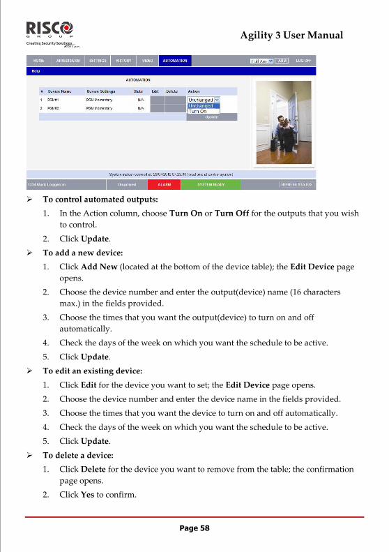
Agility 3 User Manual
Page 58
To control automated outputs:
1. In the Action column, choose Turn On or Turn Off for the outputs that you wish
to control.
2. Click Update.
To add a new device:
1. Click Add New (located at the bottom of the device table); the Edit Device page
opens.
2. Choose the device number and enter the output(device) name (16 characters
max.) in the fields provided.
3. Choose the times that you want the output(device) to turn on and off
automatically.
4. Check the days of the week on which you want the schedule to be active.
5. Click Update.
To edit an existing device:
1. Click Edit for the device you want to set; the Edit Device page opens.
2. Choose the device number and enter the device name in the fields provided.
3. Choose the times that you want the device to turn on and off automatically.
4. Check the days of the week on which you want the schedule to be active.
5. Click Update.
To delete a device:
1. Click Delete for the device you want to remove from the table; the confirmation
page opens.
2. Click Yes to confirm.

Agility 3 User Manual
Page 59
FCC Note:
This equipment has been tested and found to comply with the limits for a Class B digital
device, pursuant to Part 15 of the FCC rules. These limits are designed to provide
reasonable protection against harmful interference in a residential installation. This
equipment generates, uses and can radiate radio frequency energy and, if not installed and
used in accordance with the instructions, may cause harmful interference to radio
communications. However, there is no guarantee that interference will not occur in a
particular installation. If this equipment does cause harmful interference to radio or
television reception, which can be determined by turning the equipment off and on, the
user is encouraged to try to correct the interference by one or more of the following
measures:
a) Reorient or relocate the receiving antenna.
b) Increase the separation between the equipment and receiver.
c) Connect the equipment to an outlet on a circuit different from that to which the receiver
is connected.
d) Consult the dealer or an experienced radio/TV technician.
FCC Warning:
The manufacturer is not responsible for any radio or TV interference caused by
unauthorized modifications to this equipment. Such modifications could void the user's
authority to operate the equipment.
FCC ID: JE4AGILITY Valid for P/N RW132V441ENA
IC: 6564A-AGILITY Valid for P/N RW132V441ENA
Agility 3 User Manual
Page 60
RISCO Group Limited Warranty
RISCO Group and its subsidiaries and affiliates ("Seller") warrants its products to be free
from defects in materials and workmanship under normal use for 24 months from the date
of production. Because Seller does not install or connect the product and because the
product may be used in conjunction with products not manufactured by the Seller, Seller
cannot guarantee the performance of the security system which uses this product. Seller's
obligation and liability under this warranty is expressly limited to repairing and replacing,
at Seller's option, within a reasonable time after the date of delivery, any product not
meeting the specifications. Seller makes no other warranty, expressed or implied, and
makes no warranty of merchantability or of fitness for any particular purpose.
In no case shall seller be liable for any consequential or incidental damages for breach of
this or any other warranty, expressed or implied, or upon any other basis of liability
whatsoever.
Seller's obligation under this warranty shall not include any transportation charges or costs
of installation or any liability for direct, indirect, or consequential damages or delay.
Seller does not represent that its product may not be compromised or circumvented; that
the product will prevent any personal injury or property loss by burglary, robbery, fire or
otherwise; or that the product will in all cases provide adequate warning or protection.
Buyer understands that a properly installed and maintained alarm may only reduce the
risk of burglary, robbery or fire without warning, but is not insurance or a guaranty that
such event will not occur or that there will be no personal injury or property loss as a
result thereof.
Consequently seller shall have no liability for any personal injury, property damage or loss
based on a claim that the product fails to give warning. However, if seller is held liable,
whether directly or indirectly, for any loss or damage arising under this limited warranty
or otherwise, regardless of cause or origin, seller's maximum liability shall not exceed the
purchase price of the product, which shall be complete and exclusive remedy against
seller.
No employee or representative of Seller is authorized to change this warranty in any way
or grant any other warranty.
WARNING: This product should be tested at least once a week.
© RISCO Group 04/13 5IN2047