agilent 1260 infinity ii high-temperature elsd · this chapter provides information on...
TRANSCRIPT

Agilent 1260 Infinity II High-Temperature ELSD
User Manual

2
Notices © Agilent Technologies, Inc. 2012-2017
No part of this manual may be reproduced
in any form or by any means (including
electronic storage and retrieval or
translation into a foreign language)
without prior agreement and written
consent from Agilent Technologies, Inc. as
governed by United States and
international copyright laws.
Manual Part Number G7826-90000 Rev A
Edition 07/2017
Printed in Germany
Agilent Technologies Hewlett-Packard-Strasse 8 76337 Waldbronn
This product may be used as a component of an in vitro diagnostic system if the system is registered with the appropriate authorities and complies with the relevant regulations. Otherwise, it is intended only for general laboratory use.
Warranty The material contained in this docu- ment is provided “as is,” and is sub- ject to being changed, without notice, in future editions. Further, to the max- imum extent permitted by applicable law, Agilent disclaims all warranties, either express or implied, with regard to this manual and any information contained herein, including but not limited to the implied warranties of merchantability and fitness for a par- ticular purpose. Agilent shall not be liable for errors or for incidental or consequential damages in connection with the furnishing, use, or perfor- mance of this document or of any information contained herein. Should Agilent and the user have a separate written agreement with warranty terms covering the material in this document that conflict with these terms, the warranty terms in the sep- arate agreement shall control.
Technology Licenses The hardware and/or software described in this document are furnished under a license and may be used or copied only in accor- dance with the terms of such license.
Restricted Rights Legend If software is for use in the performance of a U.S. Government prime contract or subcon- tract, Software is delivered and licensed as “Commercial computer software” as defined in DFAR 252.227-7014 (June 1995), or as a “commercial item” as defined in FAR 2.101(a) or as “Restricted computer soft- ware” as defined in FAR 52.227-19 (June 1987) or any equivalent agency regulation or contract clause. Use, duplication or dis- closure of Software is subject to Agilent Technologies’ standard commercial license terms, and non-DOD Departments and Agencies of the U.S. Government will
receive no greater than Restricted Rights as defined in FAR 52.227-19(c)(1-2) (June 1987). U.S. Government users will receive no greater than Limited Rights as defined in FAR 52.227-14 (June 1987) or DFAR 252.227-7015 (b)(2) (November 1995), as applicable in any technical data.
Safety Notices
CAUTION A CAUTION notice denotes a hazard. It calls attention to an operating procedure, practice, or the like that, if not correctly per- formed or adhered to, could result in damage to the product or loss of important data. Do not proceed beyond a CAUTION notice until the indicated condi- tions are fully understood and met.
W ARNING A WARNING notice denotes a hazard. It calls attention to an operating procedure, practice, or the like that, if not correctly performed or adhered to, could result in personal injury or death. Do not proceed beyond a WARNING notice until the indi- cated conditions are fully under- stood and met.

3
In This Book
Agilent 1260 Infinity II HT-ELSD Service Manual
In This Book
This manual contains information on:
• Agilent 1260 Infinity II HT-ELSD (G7826A)
1 Introduction to the Detector
This chapter gives an introduction to the module, instrument overview and internal connectors
2 Site Requirements and Specifications
This chapter provides information on environmental requirements, physical and performance specifications.
3 Installing the Module
This chapter gives information about the installation of your ELSD.
4 Using the Module
This chapter explains the operational parameters of the ELSD.
5 Optimizing Performance
This chapter gives hints on how to optimize the performance or use additional devices.
6 Troubleshooting and Diagnostics
This chapter gives an overview about the troubleshooting and diagnostic features.

In This Book
4 Agilent 1260 Infinity II HT-ELSD User Manual
7 Error Information
This chapter describes the meaning of error messages, and provides information on probable causes and suggested actions how to recover from error conditions.
8 Maintenance and Repair
This chapter describes the maintenance of the ELSD.
9 Parts and Materials for Maintenance
This chapter provides information on parts for maintenance.
10 Appendix
This chapter provides addition information on safety, legal and web.

Agilent 1260 Infinity II HT-ELSD User Manual 5
Contents
Contents
1 Introduction to the Detector 7 Introduction to the ELSD 8 System Overview 9
2 Site Requirements and Specifications 15 Pre-installation Requirements 16 Site Requirements 17 Physical Specifications 20 Performance Specifications 21
3 Installing the Module 23 Unpacking the Module 24 Installing the Module 26
4 Using the Module 31 Before Using the Detector 32 Instrument Controls 32 Operational Parameters 38 General Considerations 39

Contents
6 Agilent 1260 Infinity II HT-ELSD User Manual
5 Optimizing Performance 43 Do’s and Don’ts of ELS Detection 44 Location of the Detector Module 45 Pumping systems 46 Mobile phase priming 47 Solvent recommendations 48
6 Troubleshooting and Diagnostics 49 Troubleshooting 50 Troubleshooting a GPC System 51 General Problems 52
7 Error Information 59 What Are Error Messages 60 Module Specific Error Messages 61
8 Maintenance and Repair 73 Introduction to Maintenance 74 Cautions and Warnings 75 Cleaning the Module 77 Inspection of Cables 78 Cleaning the Nebuliser 78 Cleaning Evaporator Tube 79 Putting the Instrument into Storage 80
9 Parts and Materials for Maintenance 81 Identifying Parts and Materials 82
10 Appendix 83 General Safety Information 84 The Waste Electrical and Electronic Equipment Directive 87 Radio Interference 88 Agilent Technologies on Internet 89

Agilent 1260 Infinity II HT-ELSD User Manual
1 Introduction to the Detector Introduction to the ELSD 8 System Overview 9
Basic Principles of Operation 9 Operational Parameters 12 Overview of ELS Detector 13
This chapter gives an introduction to the module, instrument overview and internal connectors
Agilent Technologies

1 Introduction to the DetectorIntroduction to the ELSD
8 Agilent 1260 Infinity II HT-ELSD User Manual
Introduction to the ELSD
The Evaporative Light Scattering Detector is a unique and highly sensitive detector for semi- volatile and non- volatile solutes in a liquid stream. It is mainly used as a concentration detector for High Performance Liquid Chromatography (GPC). The solvent stream containing the solute material is nebulized and carried by a gas flow through an evaporation chamber. The solvent is volatilized, leaving a mist of solute particles that scatter light to a photosensitive device. The signal is amplified and a voltage output provides the concentration of the solute particles passing through the light.
The Agilent 1260 Infinity II HT-ELSD may be used alone, or as part of the Agilent High Temperature GPC system. As the solvent or eluent is evaporated in the course of the analysis, the Agilent 1260 Infinity ELSD must be the last in series if used in conjunction with other detectors.
This manual instructs the user in the installation and operation of the Agilent 1260 Infinity II HT-ELSD for operation with the Agilent High-Temperature GPC system (G7820B)

Introduction to the Detector 1 System Overview
Agilent 1260 Infinity II HT-ELSD User Manual 9
System Overview
Basic Principles of Operation
Nebulization The eluent inlet is connected to the nebuliser via a heated transfer line, comprising an inner capillary tube. The incoming eluent stream is heated and passes through the heated nebuliser and is mixed with the incoming nebuliser gas stream. The mixed gas and eluent stream form an aerosol plume containing a uniform dispersion of droplets that then passes as a continuous flow into the evaporator section. Any larger droplets or the inefficiently nebulized droplets collect in the nebuliser chamber waste trap and then drain off via the waste outlet into a collection bottle.
Evaporation After nebulization the atomized spray is propelled through the evaporation tube assisted by a carrier gas. In the evaporator section the solvent is removed leaving a stream of dry particles of the analyte. A diffuser located in the evaporator assists in the drying of the particles, acting as an efficient heat exchanger, prevents ballistic particles reaching the scattering chamber and randomizes the particle plume. The ELS Detectors use patented gas flow technology in the evaporation zone to aid evaporation at low temperatures. By adding a stream of dry nitrogen (evaporation gas) at the entrance of the evaporator tube high boiling point solvents (for example, TCB) can be evaporated at much lower temperatures.

1 Introduction to the DetectorSystem Overview
10 Agilent 1260 Infinity II HT-ELSD User Manual
Detection Light in the optical chamber is passed through the instrument at right angles to the direction of particle flow. A light trap is located opposite the source of light to capture the transmitted incident beam eliminating internal reflections within the instrument body. When pure solvent is being evaporated, only its vapor passes through the light path and the amount of light scattered to the photomultiplier is small and gives a constant baseline response. When a non- volatile solute is present a particle cloud passes through the light path, causing light to be scattered. This scattered light enters the optical aperture of the detection system and generates a signal response from the photodiode in real time. The quantity of light detected is dependent on the solute concentration and solute particle size distribution.
1. Nebulisation 2. Evaporation 3. Detection
Figure 1 Principles of Operation

Introduction to the Detector 1 System Overview
Agilent 1260 Infinity II HT-ELSD User Manual 11
Theory There are four main processes by which the path of electromagnetic radiation or light can change direction, when passing through a medium containing a suspended particulate phase, see Figure 2 on page 13.
Reflection Refraction
Mie Rayleigh
Figure 2 ELSD Scattering Mechanisms
The importance of each of these processes depends on the radius of the particle (r) compared to the wavelength (») of the incident light. Rayleigh scattering is predominant when r/» is < 5·10- 2. When particle dimensions are greater than »/20 they no longer behave as point sources, and Mie scattering becomes predominant. Once particle size approaches the wavelength of incident light then reflection and refraction begin to prevail.
The relative importance of refraction and reflection can be understood by examining the effects of the incident light on a single spherical particle whose equilateral axis lies in the same plane as the photodetector and light source. With this configuration, refraction is of greater significance than reflection. The majority of organic compounds have refractive indices between 1.3 and 1.5. Changes in the refractive index within this range will not greatly affect the quantity of light reaching the detector. This accounts for similarities in the sensitivity of the instrument to various compounds.

1 Introduction to the DetectorSystem Overview
12 Agilent 1260 Infinity II HT-ELSD User Manual
Operational Parameters The ELS Detector responds to all compounds that are less volatile than the mobile phase and is independent of a compound’s optical properties. It therefore provides advantages over other spectroscopic detectors for detecting compounds that are deficient in a UV chromophore or fluorophore.
The removal of the mobile phase within an ELSD is typically achieved by setting the evaporator temperature at, or close to, the eluent’s boiling point (e.g. 100°C) in order to remove the solvent.
However, for GPC solvents, such as Trichlorobenzene (TCB) they have boiling points (e.g. 214°C) above the operating temperature of conventional ELS detectors.
The High- Temperature ELSD u s e s patented evaporation gas technology, t o aid the evaporation of high-boiling point GPC solvents at temperatures within its typical operating range.
Therefore, unlike other ELS detectors, the Agilent HT-ELSD is able to evaporate TCB at an evaporation temperature of 120°C. This method of operation ensures that the ELSD sensitivity is maximized for low molecular weight polymers.
Introduction to the Detector 1 System Overview
Agilent 1260 Infinity II HT-ELSD User Manual 13
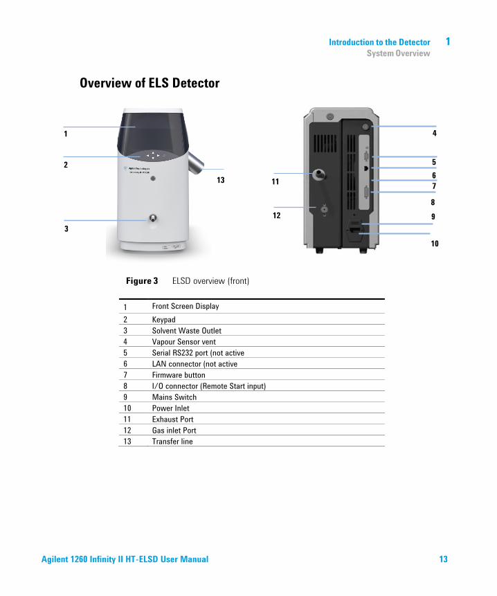
Overview of ELS Detector
Figure 3 ELSD overview (front)
1 Front Screen Display 2 Keypad 3 Solvent Waste Outlet 4 Vapour Sensor vent 5 Serial RS232 port (not active 6 LAN connector (not active 7 Firmware button 8 I/O connector (Remote Start input) 9 Mains Switch 10 Power Inlet 11 Exhaust Port 12 Gas inlet Port 13 Transfer line
1
2
3
11
12
4
5
8
7
9
6
10
13

1 Introduction to the DetectorSystem Overview
14 Agilent 1260 Infinity II HT-ELSD User Manual
Table 1 ELS Detector I/O connections
I/O description Pin number
Inputs Injection Sync 13 & ground
Remote A/Z 7 & ground
Output Pump stop contact closure – normally open 3 & 10
Ground (to case) 1, 5, 6, 11
In order to make appropriate remote start and A/Z connections from a third party system, a Remote Start Cable can be purchased from Agilent Technologies

Agilent 1260 Infinity II HT-ELSD User Manual
2 Site Requirements and Specifications Pre-installation Requirements 16 Site Requirements 17 Physical Specifications 20 Performance Specifications 21
Specifications 21 Specification Conditions 22
This chapter provides information on environmental requirements, physical and performance specifications.
Agilent Technologies

2 Site Requirements and SpecificationsPre-installation Requirements
16 Agilent 1260 Infinity II HT-ELSD User Manual
Pre-installation Requirements
For a detailed description of the environmental and operating requirements of the ELSD, please refer to the Site Preparation Checklist.
This manual will give you an overview of the ELS detector, and describe its operation in more detail.

Site Requirements and Specifications 2 Site Requirements
Agilent 1260 Infinity II HT-ELSD User Manual 17
Site Requirements
A suitable environment is important to ensure optimal performance of the instrument, please refer to the Site Preparation Checklist for more details.
Power Considerations Check the operating voltage of your instrument on the IEC inlet fuse holder on rear of unit.
WARNING Hazard of electrical shock or damage of your instrumentationcan result, if the devices are connected to a line voltage higher than specified.
➔ Connect your instrument to the specified line voltage only.

2 Site Requirements and SpecificationsSite Requirements
18 Agilent 1260 Infinity II HT-ELSD User Manual
CAUTION Inaccessible power plug.In case of emergency it must be possible to disconnect the instrument from the power line at any time.
➔ Make sure the power connector of the instrument can be easily reached andunplugged.
➔ Provide sufficient space behind the power socket of the instrument to unplug thecable.
Power Cords Your detector is delivered with a power cord which matches the wall socket of your particular country or region. The plug on the power cord which connects to the rear of the instrument is identical for all types of power cord.
WARNING Absence of ground connection or use of unspecified power cordThe absence of ground connection or the use of unspecified power cord can lead to electric shock or short circuit.
➔Never operate your instrumentation from a power outlet that has no groundconnection.
➔ Never use a power cord other than the Agilent Technologies power cord designedfor your region.
WARNING Use of unsupplied cablesUsing cables not supplied by Agilent Technologies can lead to damage of the electronic components or personal injury.
➔ Never use cables other than the ones supplied by Agilent Technologies to ensureproper functionality and compliance with safety or EMC regulations.

Site Requirements and Specifications 2 Site Requirements
Agilent 1260 Infinity II HT-ELSD User Manual 19
WARNING Unintended use of supplied power cordsUsing power cords for unintended purposes can lead to personal injury or damage of electronic equipment.
➔ Never use the power cords that Agilent Technologies supplies with this instrumentfor any other equipment.

2 Site Requirements and SpecificationsPhysical Specifications
20 Agilent 1260 Infinity II HT-ELSD User Manual
Physical Specifications
Table 2 Physical Specifications
Type Specification Comments
Weight 11 kg
Dimensions (height × width × depth)
415 x 200 x 450 mm (16.3x 7.9 x 17.7 inches)
Line voltage 100 – 240 VAC, ± 10 % Wide-ranging capability
Line frequency 50 or 60 Hz, ± 5 %
Power consumption 200 VA
Ambient operating temperature
Ambient non-operating temperature
10–30°C (50–86 °F)
-40 – 70 °C (-40 – 158 °F)
Humidity < 80 % r.h. at 40 °C (104 °F) Non-condensing
Operating altitude Up to 2000 m (6562 ft)
Non-operating altitude Up to 4600 m (15091 ft) For storing the module
Safety standards: IEC, CSA, UL
Installation category II, Pollution degree 2 For indoor use only.

Site Requirements and Specifications 2 Performance Specifications
Agilent 1260 Infinity II HT-ELSD User Manual 21
Performance Specifications
Specifications The instrument is suitable for indoor use only and is classified suitable under the following categories (EN 61010- 1):2010
• Installation category II
• Pollution degree 2
• Safety class 1
Table 3 Performance Specification of the ELS Detector
Type Specification
Light Source LED 480 nm (Class 1 LED Product)
Detector PMT with digital signal processing
Nebuliser OFF, 25 – 160 °C
Evaporator OFF, 25 – 120 °C
Transfer Line OFF, 25 – 160 °C
Neb Gas Flow 0.2 – 0.5 SLM
Short Term Noise <0.2 mV under specified conditions. See “Specification Conditions” on page 26.
Drift <1 mV/h under specified conditions. See “Specification Conditions” on page 26.
Operating Pressure 65 – 100 psi (4.2 – 6.9 bar) (80 psi recommended)
Eluent Flow range 0.5 – 5.0 mL/min
Analogue Output 10Hz

2 Site Requirements and SpecificationsPerformance Specifications
22 Agilent 1260 Infinity II HT-ELSD User Manual
Table 3 Performance Specification of the ELS Detector
Type Specification
Communication Analogue Output
Remote operation Remote Start Input
Safety features Gas shut off Valve, Leak Detection, Over-temperature protection
Specification Conditions
Table 4 Reference conditions
Mobile phase Trichlorobenzene Flow rate 1ml/min Transfer line temperature 160°C Nebuliser Gas flow 0.2 SLM Nebuliser Temperature 160°C Evaporator Temperature 120°C PMT Gain 1 Smoothing 50
Drift & noise test requires a stabilization period of 60mins. Our published drift specification is based on these conditions. Larger ambient temperature changes or insufficient equilibration will result in larger drift & noise.

Agilent 1260 Infinity II HT-ELSD User Manual
3 Installing the Module Unpacking the Module 24 Installing the Module 26
Connecting the Detector to your LC System 26 Checking Operation of the ELS Detector 29
This chapter gives information about the installation of your ELSD.
Agilent Technologies

3 Installing the ModuleUnpacking the Module
24 Agilent 1260 Infinity II HT-ELSD User Manual
Unpacking the Module
Damaged Packaging If the delivery packaging shows signs of external damage, please call your Agilent Technologies sales and service office immediately. Inform your service representative that the instrument may have been damaged during shipment.
CAUTION "Defective on arrival" problemsIf there are signs of damage, please do not attempt to install the module. Inspection by Agilent is required to evaluate if the instrument is in good condition or damaged.
➔ Notify your Agilent sales and service office about the damage.
➔ An Agilent service representative will inspect the instrument at your site andinitiate appropriate actions.

Installing the Module 3 Unpacking the Module
25 Agilent 1260 Infinity II HT-ELSD User Manual
Delivery Checklist Unpack the ELSD and accessories, and ensure that all parts and materials shown in the table below have been delivered with your module. Report any missing or damaged parts to your local Agilent Technologies sales and service office.
p/n Description
G7826A Agilent 1260 Infinity II High-Temperature ELSD
G7826-60500 Agilent ELSD Heated Transfer Line Assy (pre-installed)
PL0890-0300 Analogue Output cable
G4260-63001 1260 Infinity II Trigger Cable
PL0890-0305 Gas inlet tube (2 m)
PL0890-0310 Rear exhaust hose (PVC-2 m)
IN2-25388 Solvent waste tube (1.9 m)
N/A One power cord (region dependent)

3 Installing the ModuleInstalling the Module
26 Agilent 1260 Infinity II HT-ELSD User Manual
Installing the Module
Connecting the Detector to your GPC System The ELS detector must be installed by an Agilent service representative.
Your Agilent service representative will:
• Unpack the ELSD.
• Remove all packing list items that are shipped with the instrument andpresent them to you for review.
• Unpack the accessories supplied with the instrument and check thatyou have received everything on the packing lists.
• Install your ELS detector.
1 Place the module on the bench in a vertical position.
2 Connect the power cord to the IEC inlet at the rear of the unit.
3 Ensure the power switch of the module is OFF (switch stands out).
4 Attach the 4 mm OD gas tube into the gas inlet port at the rear of theinstrument. The gas connection is a push- in fitting.
5 Connect the solvent waste tube to the waste outlet at the front of the detector and position the other end into a waste collection bottle.
6 Connect the front outlet tube to the waste bottle using the supplied tubing.
7 Ensure that the end of the waste tube is below the height of the waste outlet from the instrument.
. Though it will not cause any damage, if the solvent waste tube becomes submersed below the solvent level inside the waste container positive pressure will be exerted on the nebuliser chamber leading to excessive baseline noise

Installing the Module 3 Installing the Module
Agilent 1260 Infinity II HT-ELSD User Manual 27
WARNING Risk of intoxication and contamination of detectorToxic evaporation and accumulation of condensing solvent
➔ The exhaust must be extracted to a suitable fume extraction system.
➔ Attach one end of the exhaust hose to the rear of the unit.
➔ Ensure the exhaust hose has an upward slope from the detector so that anycondensed solvent is collected in the waste bottle at the front of the unit and toprevent it accumulating in the tubing.
➔ Make sure the other end of the exhaust hose is vented to a fume hood or otherdisposal unit.
CAUTION Negative or positive backpressure at the exhaustBaseline noise and reduced performance of the detector
➔ Do not connect the exhaust tubing directly to the extraction unit.
8 Connect the exhaust hose between the exhaust outlet and a fume hood.
9 Connect the analogue cable to an Agilent DataStream (G7825A) or Agilent Universal interface box (G1390B)
10 Connect the I/O cable to the Agilent HT-GPC System or pump.
11 Connect the heated transfer line to the HT-GPC system
12 Turn on the source gas to a pressure of about 4.2 – 6.9 bar.
NOTE NOTE

3 Installing the ModuleInstalling the Module
28 Agilent 1260 Infinity II HT-ELSD User Manual
OTE The ELS detector is equipped with 2 contact closures (normally-open) for stopping the operation of a pump if the unit reports an error condition. Pump stop facility must be connected The eluent from the chromatography system is connected to the side port of the ELS Detector via a heated transfer line. Avoid pulling or stressing the heated transfer line as this could detach the inner nebulizer and lead to internal leaks or poor performance
For further information on how to connect the HT-ELSD to the Agilent HT-GPC system, please refer to Agilent HT-GPC User Manual

Installing the Module 3 Installing the Module
Agilent 1260 Infinity II HT-ELSD User Manual 29
Checking Operation of the ELS Detector 1 Switch on the ELS Detector.
2 Set operational parameters (i.e. nebuliser and evaporator temperature), via the front panel. Then set the ELS detector status to RUN mode.
NOTE When the unit has reached temperature, the baseline noise should be checked to ensure that it is < 0.2 mV peak-peak. This verifies that the gas supply is clean and dry.
3 If the baseline noise is within the limits, autozero the detector. However, if the baseline noise is outside the limits, refer to the Troubleshooting section for steps to rectify this.
4 Turn on the eluent flow and allow the system to stabilize for at least 15 mins.
5 Again, check the baseline noise.
Where noise and all other conditions are acceptable, the instrument is ready to begin work.
Baseline noise should not have increased significantly and should be ≤0.5 mV. Typically, filtered trichlorobenzene should give no more than 1.0 mV peak-peak
NOTE Some GPC solvents contain additives or stabilizers that can generate increased noise levels.

3 Installing the ModuleInstalling the Module
30 Agilent 1260 Infinity II HT-ELSD User Manual

Agilent 1260 Infinity II HT-ELSD User Manual
4 Using the Module
Before Using the Detector 32 Instrument Controls 32
Display Screen 32 Keypad 33 Main menu bar 33 Sub-Menu Screen 33 Status Mode 34 Error conditions 35 Clearing an Error 35
Operational Parameters 36 Transfer Line Temperature 36 Evaporator Temperature 36 Nebuliser Temperature 36 Nebuliser Gas Flow 37 Detector Gain (PMT) 37 Response Time (Smoothing) 37Light Source Intensity (LED) 38 Power Mode 38 Data Output Rate (Hz) 38
General Considerations 39 Solvent Recommendations 40 Sample Preparation 41 Column Considerations 41 Transferring ELSD Temperature Methods 41
This chapter explains the operational parameters of the ELSD.
Agilent Technologies

4 Using the ModuleOperational Parameters
32 Agilent 1260 Infinity II HT-ELSD User Manual
Before Using the Detector
Before using the detector, make sure solvent flow to the detector is off and all communication, waste and exhaust tubes are fitted. Ensure the trigger cable is attached to the remote port of the solvent delivery module
Instrument Controls
The ELS Detector is used as a standalone detector via the front keypad and screen, as shown in Figure 7 on page 54
Display Screen The graphical interface on the front of the instrument displays the current method, status, evaporator temperature, nebuliser temperature, gas flow and output of the instrument. Operating parameters can be altered via the interactive menu bar at the bottom of the display.
Figure 7 ELSD Display Screen

Using the Module 4 Operational Parameters
Agilent 1260 Infinity II HT-ELSD User Manual 33
Keypad The four arrows on the front of the instrument are used to navigate within the interactive menu bar. The detector can be auto-zeroed by pressing the AZ/Stop key.
Main menu bar To change the current settings, use the arrow keys to navigate across the interactive menu bar until the desired option is flashing. Using the up/down arrow keys alter the parameter to the desired setting. In order to action any changes, the cursor must be returned to the “Home” position
Sub-Menu Screen
The sub- menu screen is accessed from the front screen by selecting the key: This screen allows changes to the following electronic parameters:
PMT Set Signal Gain SMTH Set Time Constant LED Set Light source Intensity PWR Set Mode of ELSD when powered up

4 Using the ModuleOperational Parameters
34 Agilent 1260 Infinity II HT-ELSD User Manual
Figure 8 G7826A sub menu screen
Status Mode The ELS Detector can be operated in two modes; STANDBY or RUN, both of which are described over page.
To display the current mode and/or select a new mode, highlight the MODE function on the instrument display. The current mode will now be displayed on the screen. Using the arrow keys, scroll up or down until the desired option is displayed. The instrument acknowledges the command by displaying the mode of operation in the top right hand corner of the screen.
Standby The STANDBY mode is the “ground state” of the ELS detector, which is by default initiated automatically after power on (default can be changed using Power Mode, “Power Mode” on page 40). In STANDBY mode the heaters and light source are switched off, and the gas manifold valve is closed at power on. The STANDBY mode gives the user a control platform in which to set- up the operational parameters (gas flow, nebuliser and evaporator temperatures) before switching the unit into RUN mode. The instrument will default to STANDBY mode should an error occur on the instrument.
When the instrument is switched from RUN mode to STANDBY mode, following a command or error, then the gas management system is invoked and the gas flow set to a minimum flow of 1.2 SLM for 15 min before the gas manifold valve is closed. This minimum “blanket” gas is enough to nebulise and evacuate solvent should the instrument default to STANDBY mode with solvent still flowing.

Using the Module 4 Operational Parameters
Agilent 1260 Infinity II HT-ELSD User Manual 35
CAUTION Flooding the detectorIf the instrument is left in Standby mode for longer than 15 minutes, gas flow to the unit is stopped to minimize gas usage.
➔ The solvent pump must be turned off if the ELSD is going to be left in Standby modelonger than 15 minutes to prevent solvent flooding the detector.
RUN The RUN mode is the detector’s operational mode. In this mode, the instrument is controlled at the set temperatures and gas flow, and the system is fully operational. During heating or cooling the instrument will display NOT READY to show the system has not reached the set conditions. When the instrument has equilibrated READY will be displayed and the instrument is ready for use.
Error conditions The ELS Detector is equipped with a number of sensors and error checking facilities to ensure safe operation. If an error is detected the instrument gives an audible warning and a visible description of the error condition. In event of any error condition, the unit defaults into the STANDBY mode in which the heaters, light source and gas are turned off. A complete list of instrument errors and remedial actions are given in the troubleshooting section of this manual.
CAUTION Clearing an Error
Once the source of the problem has been corrected, select RUN mode to put the ELSD back into its operational state. If the problem has not been rectified the ELSD will repeatedly error when RUN mode is selected.

4 Using the ModuleOperational Parameters
36 Agilent 1260 Infinity II HT-ELSD User Manual
Operational Parameters
Transfer Line Temperature The transfer line (xfer) temperature must be set at the correct value for optimum performance. This should be set at, or close to, the HT-GPC system temperature. For trichlorobenzene the recommended temperature for the transfer line is 160°C.
Evaporator Temperature The evaporator temperature must be set at the correct value for optimum performance. This should be set close to the boiling point of the mobile phase, or as high as possible if the boiling point exceeds the temperature range of the ELSD.
For example, the evaporator temperature for TCB should be 120°C, whilst for Tetrahydrofuran it should be set to 40°C
An insufficient evaporator temperature can lead to high baseline noise and damage to the optics.
Nebuliser Temperature The nebuliser temperature can be used to optimize signal response in addition to evaporator temperature. Higher nebuliser temperatures increase peak response, but high baseline noise can occur if the temperature exceeds the boiling point of the mobile phase. To prevent blockages, it is critical that the nebulizer temperature is higher enough to maintain solubility of the sample within the mobile phase.
For example, it is recommended to operate the nebulizer temperature at 160°C when analyzing polyethylene samples in trichlorobenzene.

Using the Module 4 Operational Parameters
Agilent 1260 Infinity II HT-ELSD User Manual 37
Nebuliser Gas Flow The nebuliser gas flow is used to control the detector’s nebulisation process. The gas value is set per the mobile phase composition or viscosity. It is recommended to use higher gas flows (e.g. 0.4 SLM) i f t h e eluents has a high viscosity at the set nebulizer temperature.
The nebulizer gas has a major influence on the detector’s sensitivity. Small changes in nebulizer gas flow can have a significant impact on the detectors performance,
Detector Gain (PMT) This parameter sets the factor by which the detector output signal isamplified. The gain setting does not change the sensitivity of the detector, but merely amplifies the captured signal by the inputted factor. The gain can be adjusted from 1 to 10 in increments of 0.1.
When setting the PMT (or Gain), both the signal and noise are simply amplified by the value set, so S/N values are unaffected. The raw signal output displayed on the parameter screen will reflect this increase or decrease in signal amplification.
Please note that the instrument output displayed on the main operating screen does not alter following a PMT change, thus the recorded baseline position will remain unchanged. Confirmation of a PMT change will be obvious by the change in baseline noise.
Response Time (Smoothing) The data outputted from the detector can be averaged to produce a smoother response. The smoothing width is set to the number of data points over which the data is averaged and can be regarded as a digital time constant. The smoothing range is settable from 1 – 70 , (in increments of 1) which translates to 0.1 – 7.0 s.
For most GPC applications, a value of 50 (5 s) is satisfactory. However, for broader peaks higher values maybe required of

4 Using the ModuleOperational Parameters
38 Agilent 1260 Infinity II HT-ELSD User Manual
Light Source Intensity (LED) The ELS detector’s LED intensity can be adjusted depending on the sample concentration or loading. The intensity can be adjusted between 1-100% and the value is retained even after a power cycle.
This feature is extremely useful when analyzing samples that are prepared at a high concentration required for a refractive index detector and would otherwise exceed the dynamic range of the other ELS detectors. Reducing the LED intensity eliminates the need to prepare samples at different concentrations.
Power Mode The instrument can be configured from the front panel sub- menu (see “Sub- Menu Screen” on page 55), to start in either RUN or STANDBY mode when the unit is switched on via the rear power button.
To configure the Power Mode, select the required Status Mode (i.e. STANDBY or RUN) you wish the unit to start- up in from the sub menu screen (see “Sub- Menu Screen” on page 55). The selected option will take effect the next time the power is cycled. If RUN mode is selected as the desired Power mode, then the instrument will use the operating parameters stored in memory. In the unlikely event that the instrument encounters a fault during power- up the unit will automatically switch to STANDBY mode.
NOTE All ELSD conditions are retained on power cycling of the ELSD detector.

Using the Module 4 General Considerations
Agilent 1260 Infinity II HT-ELSD User Manual 39
General Considerations
The ELS Detector should be thought of as a detector like any other designed for liquid chromatography. The main distinguishing feature is the ability to evaporate the solvent from the column eluent. Therefore, normal system set- up precautions should be remembered when starting to use the instrument. Any solvent intended for use with the ELSD should be fully miscible with any previously used in the liquid chromatograph; if there is any uncertainty, then a mutually miscible solvent should be run through the system as an intermediate liquid. The sample loop should also be flushed with miscible solvent where necessary. The intended eluent should be thoroughly degassed, contain no non- volatile salts or material and should be fully compatible with the column(s). All connections should be made with zero dead volume fittings and tubing with an I.D. d0.254 mm (d0.010 in).
The ELSD requires nitrogen of purity >98 %, at an inlet pressure of 4.2 – 6.7 bar. If in- house nitrogen is not available, then we recommend the use of a nitrogen generator for a constant uninterrupted supply of high purity gas. Air can be used with non- flammable solvent systems. The eluent of choice should be fully volatile under the chosen detector parameters – any non- volatilized eluent will increase baseline noise and reduce sensitivity.
The ELS Detector is a destructive technique and must be placed last when used in series with other detectors.

4 Using the Module General Considerations
40 Agilent 1260 Infinity II HT-ELSD User Manual
Solvent Recommendations Any solvent intended for use with the ELS Detector should be thoroughly degassed, filtered and fully compatible with the column(s). Solvents that are not properly degassed may cause problems at nebulization leading to a poor reproducibility.
Non- Volatile buffers are not compatible with the ELS Detector and should not be used.
Tetrahydrofuran (THF) stabilized with BHT, may increase the baseline noise level. Where possible unstabilized THF should be used with the ELS detector.
WARNING Solvents with auto-ignition temperatures <190°C must not be used with the ELSD
Table 7 Auto-ignition temperatures of common GPC solvents with ELS detection
Solvent Auto-ignition Temperature (°C)
Dibutoxymethane 220
Tetrahydrofuran 321
Dimethlysulphoxide 215
Toluene 530
Acetone 540
1,2,4 Trichlorobenzene (TCB) 570
m-Cresol 575
Chloronapthelene 558

Using the Module 4 General Considerations
Agilent 1260 Infinity II HT-ELSD User Manual 41
Sample Preparation Samples containing particulate matter should be filtered through a 0.45 µm filter prior to injection.
Column Considerations The ELS detector will detect all non- volatile components in the mobile phase, which includes column- packing material. Column packing material will become chemically and mechanically broken down over the lifetime of the column, causing particles to enter the ELSD. This column “shedding” will lead to extremely high baseline.
Transferring ELSD Temperature Methods The direct transfer of ELSD operating conditions from the PL-ELS 1000 ELSD will not provide equivalent performance.
The HT-ELSD settings should be optimized according to the guidelines outlined in “Operational Parameters” on page 12.

4 Using the Module General Considerations
42 Agilent 1260 Infinity II HT-ELSD User Manual

Agilent 1260 Infinity II HT-ELSD User Manual
5 Optimizing Performance
Do’s and Don’ts of ELS Detection 44 Location of the Detector Module 45 Pumping systems 46 Mobile phase priming 46 Solvent recommendations 47
This chapter gives hints on how to optimize the performance or use additional devices.
Agilent Technologies

5 Optimizing PerformanceDo’s and Don’ts of ELS Detection
44 Agilent 1260 Infinity II HT-ELSD User Manual
Do’s and Don’ts of ELS Detection
CAUTION Decreased performanceHigh pressures on the internal chamber will lead to increased baseline noise and low sensitivity.
➔ NEVER block the exhaust outlet.
➔ NEVER allow the solvent waste outlet tube to become immersed in the wastesolvent.
➔ When placing more than one GPC detector in series, always place the ELS detectorlast.
➔ Avoid excessive nebuliser gas flow rates as it can empty the nebulizer solvent trap
➔ Only use volatile mobile phase additives.
Optimizing Performance 5 Location of the Detector Module
45 Agilent 1260 Infinity II HT-ELSD User Manual
Location of the Detector Module
Place the detector alongside your G P C system. The ELSD must be placed to the left-hand side of you GPC system due to the location and length of the heated transfer line.
Provide approximately four inches (10 cm) of space behind the unit so that the cooling fan intake is not impeded, and to allow easy access to the rear panel.
The ELS detector can be placed within 2 meters of an extraction unit, using the exhaust tube provided.

5 Optimizing Performance Pumping systems
46 Agilent 1260 Infinity II HT-ELSD User Manual
Pumping systems
It is recommended to use service and maintain your solvent delivery system to ensure minimize flow pulsation that would otherwise lead to nebulization problems. Inconsistent solvent flow will result in poor reproducibility.
A backpressure regulator maybe necessary on certain pumps with certain solvents in order to minimize pulsation. This can be achieved by the column itself or a coil of 0.127 mm (0.005 in) ID tubing placed between the pump and the column.

47
Optimizing Performance 5 Mobile phase priming
Agilent 1260 Infinity II HT-ELSD User Manual
Mobile phase priming
The ELS detector does not require any mobile phase priming, other than that required to prime the solvent through the pump, damper, injector, column, etc. It is recommended that priming of the GPC system be performed without the ELS detector attached, to prevent non- volatile impurities contaminating the ELS detector.
Solvent recommendations
The thermal cut-off temperature of the detector and the auto-ignition temperature of the solvent will determine the type of solvents compatible with the HT-ELS detector (see table 7). GPC solvent shown below must not be used.
• Dimethylsulphoxide (DMSO)
Greater care and attention to instrument cleaning procedures should be exercised with these high boiling GPC solvents. It is recommended that any solvent be flushed from the detector for overnight and weekend storage.

5 Optimizing PerformanceSolvent recommendations
48 Agilent 1260 Infinity II HT-ELSD User Manual

Agilent 1260 Infinity II HT-ELSD User Manual
6 Troubleshooting and Diagnostics Troubleshooting 50 Troubleshooting an GPC System 51 General Problems 52
Baseline noise 52 Baseline spikes 53 Low sensitivity 53 Spiky peak tops but flat baseline 54 Large Baseline offset 54 Peak tailing 54 Instrument Fails to zero 55 No power 55 No response (completely flat baseline) 56Temperature error as soon as instrument powered on 56 Display not on, but power connected 57 Evaporator Temperature reads zero at start-up and cannot be changed 57Vapor sensor error occurs, but there is no solvent or vapor leak inside unit 57 High back-pressure from detector 58
This chapter gives an overview about the troubleshooting and diagnostic features.
Agilent Technologies

6 Troubleshooting and DiagnosticsTroubleshooting
50 Agilent 1260 Infinity II HT-ELSD User Manual
Troubleshooting
If a problem is encountered Agilent Technologies advises that the troubleshooting section should be followed first to resolve the problem. If there is an error or fault and you follow the recommended course of action and the result is not satisfactory, then please direct the matter to Agilent Technologies or your local distributor.
Malfunctions within the ELS Detector can arise from three general sources:
• The ELS Detector itself can be dirty or operating outside specification.
• The GPC system can have a broken, dirty, or non- optimally operatingcomponent, but the problem is manifesting itself in the ELS Detector.
• A mobile phase and/or column problem, which by its very nature isspread throughout the GPC system but appears as a malfunction ofthe ELS Detector.
To troubleshoot the ELS Detector, you must be able to separate the performance of the ELS Detector within the GPC system from its performance outside the GPC system. This section begins with guidelines for testing the ELS Detector as a stand- alone. See “Module Specific Error Messages” on page 91 for possible cause and suggested solution.

Troubleshooting and Diagnostics 6 Troubleshooting a GPC System
51 Agilent 1260 Infinity II HT-ELSD User Manual
Troubleshooting a GPC System
Standard practice is to add one component at a time back into the GPC system so that the component causing the problem is easily identified if/when the condition reoccurs.
Begin troubleshooting by adding the pump to the ELS Detector first and finish by adding the column last. If another type of detector is available, use it before the ELS Detector to aid in troubleshooting.

6 Troubleshooting and DiagnosticsGeneral Problems
52 Agilent 1260 Infinity II HT-ELSD User Manual
General Problems
Baseline noise
Probable cause Suggested actions
1 Poor nebulisation Increase the temperature or gas flow of the nebulizer until the baseline noise decreases
2 Insufficient evaporation • Decrease the nebulisation temperature• Decrease the nebuliser gas flow rate
3 Non-volatile additive in mobile phase Use a volatile mobile phase as shown
4 Pressure difference created inside nebuliser chamber
• Ensure that the end of the liquid waste tubeis not immersed in liquid
• Ensure that the exhaust tube at rear of unitis not blocked, or extraction is too strong
5 Pump pulsations, especially in microbore applications where low flow rates are used
• Use a pulse free pump • Increase the back pressure on the pump by
fitting a back pressure column between thepump and the injection valve
• Use a pulse dampener directly after thepump in the system

Troubleshooting and Diagnostics 6 General Problems
53 Agilent 1260 Infinity II HT-ELSD User Manual
Baseline spikes
Probable cause Suggested actions
1 Particulate matter in the gas supply Filter the incoming gas, or change the supply
2 Column shedding Replace column or fit an inline filter with a 0.2 µm membrane filter directly after the column
3 Poor nebulisation • Check solvent flow rate into ELSD is constant• Check inlet gas flow is >65 psi and stable
4 Insufficient evaporation Decrease the nebulisation temperature• Decrease the nebuliser gas flow rate
5 Non-volatile additive in mobile phase Replace additive in mobile phase with volatile buffer
Low sensitivity
Probable cause Suggested actions
1 Partial blockage in nebuliser or nebulizer inlet tube
Pump 1ml/min TCB into ELSD at highest nebulizer temperature for several hours
2 Internal solvent trap is empty Fill the front solvent trap with liquid until any excess flows out through front drain tube
3 Gas pressure too low Ensure inlet gas pressure >65 psi
4 LED power too low Ensure LED power is set to 100 %
5 Optical chamber is contaminated Clean or replace optical chamber
6 Light source power has decayed Replace light source
7 Diffuser saturated with solvent Stop the eluent flow and increase the evaporator temperature to maximum. Increase the Neb flow rate to maximum and wait 3 hours

6 Troubleshooting and DiagnosticsGeneral Problems
54 Agilent 1260 Infinity II HT-ELSD User Manual
Spiky peak tops but flat baseline
Probable cause Suggested actions
1 Inconsistent nebulization Check pump flow
2 Incorrect gas being used Change gas to nitrogen or evaluate different nitrogen sources
3 Poor regulation of inlet gases If using bottled gas, check that gas regulator is functioning correctly and giving consistent flow
4 Insufficient smoothing The broader the peaks, the higher the smoothing value is required. Increase smoothing value.
5 Sample precipitation during nebulization • Reduce sample concentration
• Increase transfer line and nebulizertemperature
6 Inconsistent pump flow rates Check pump manual for troubleshooting
Large Baseline offset
Probable cause Suggested actions
1 Inefficient evaporation Increase the evaporator temperature and/or nebulizer gas flow
2 High concentration of non-volatile buffer or stabiliser
Use a lower concentration of stabiliser, unstabilised solvent or a more volatile buffer
3 Contaminated diffuser Perform cleaning procedure
4 Optics Heater failed Exchange optics heater

Troubleshooting and Diagnostics 6 General Problems
55
Agilent 1260 Infinity II HT-ELSD User Manual
Peak tailing
Probable cause Suggested actions
1 Eluent particles lingering in the optical chamber
Increase evap gas flow rate
2 Poor chromatography Optimize GPC separation
Instrument Fails to zero
Probable cause Suggested actions
1 Offset too high or output unstable due to impurity in mobile phase
• Stop pump flow and switch off unit. Restart
unit and A/Z without liquid flowing • If problem persists, please follow
cleaning instructions • Optical section contaminated and requires
cleaning
No power
Probable cause Suggested actions
1 Mains lead not connected Attach mains lead to socket and inlet on rear of instrument
2 Fuse failure Replace fuse
3 Power supply failure Call Agilent Service representative

6 Troubleshooting and DiagnosticsGeneral Problems
56 Agilent 1260 Infinity II HT-ELSD User Manual
No response (completely flat baseline)
Probable cause Suggested actions 1 Data acquisition leads not connected Ensure connectors to computer or integrator
are sound
2 Light source inactive Check LED is functioning correctly, by stopping solvent flow, cycling the power. Then reading the offset value in RUN mode
3 Output below 0 mV Stop pump flow and A/Z without liquid Flowing
4 Instrument in STANDBY mode Select RUN mode
5 Nebuliser or nebuliser inlet tube blocked Manually syringe solvent into ELSD front Inlet port to remove obstruction
Temperature error as soon as instrument powered on
Probable cause Suggested actions
1 Temperature probe fault or disconnected • Check RTD connections• If RTD connections are ok, check resistance
across heater and thermal fuse. Replace ifeither are open circuit.

Troubleshooting and Diagnostics 6 General Problems
57
Agilent 1260 Infinity II HT-ELSD User Manual
Display not on, but power connected
Probable cause Suggested actions
1 Instrument Power Supply The power supply is faulty and needs replacing.
2 Faulty display Replace display
Evaporator Temperature reads zero at start-up and cannot be changed
Probable cause Suggested actions
1 Faulty Evaporator assembly • Replace evaporator assy
Vapor sensor error occurs, but there is no solvent or vapor leak inside unit
Probable cause Suggested actions
1 Solvent vapor near the front of unit is being drawn into the unit
Remove any solvent bottle or solvent leak that is directly in front of the detector
2 Faulty Vapor sensor Check the rear vapor sensor is not damaged/bent

6 Troubleshooting and Diagnostics General Problems
58 Agilent 1260 Infinity II HT-ELSD User Manual
High back-pressure from detector
Probable cause Suggested actions
1 Nebuliser or nebuliser inlet tube blocked Replace inner nebulizer capillary

Agilent 1260 Infinity II HT-ELSD User Manual
7 Error Information
What Are Error Messages 60 Module Specific Error Messages 61
Internal temperature exceeded lower limit 61 Internal temperature exceeded upper limit 61 On-board Vapor sensor failed 62 Rear Vapor sensor failed 62 Vapor detected 62 Leak detected 63 Fan Failed 63 Fan Stopped 64 Nebulizer temperature limit exceeded 64 Evaporator temperature limit exceeded 64 LED light source error 64 Nebuliser gas flow rate limit exceeded 65 Invalid Nebulizer temperature 65 Invalid Evaporator temperature 66 Nebuliser Under Current 66 Nebuliser Over Current 67Leak Sensor failed 67 Transfer Line Limit Exceeded 67 Invalid Transfer Line Temperature 68 Evaporator Failed to Reach Temperature 68 Nebuliser Failed to Reach Temperature 69 Transfer Line Failed to Reach Temperature 70 Transfer Line Under Current 70 Transfer Line Over Current 71 Transfer Line Readout Error 71
This chapter describes the meaning of error messages, and provides information on probable causes and suggested actions how to recover from error conditions.
Agilent Technologies

8 Error Information What Are Error Messages
60 Agilent 1260 Infinity II HT-ELSD User Manual
What Are Error Messages
Error messages are displayed o n t h e f r o n t p a n e l o f t h e d e t e c t o r when an electronic, mechanical, or hydraulic (flow path) failure occurs which requires attention before the analysis can be continued (for example, repair, or exchange of consumables is necessary).

Error Information 7 Module Specific Error Messages
61 Agilent 1260 Infinity II HT-ELSD User Manual
Module Specific Error Messages
The following errors are detector specific.
Internal temperature exceeded lower limit Error ID: 10
Air temperature inside the instrument is d10 °C
Probable cause Suggested actions
1 The environmental temperature is outside the specified operating limits of the instrument
• Increase ambient temperature wheredetector is located
• Move the detector to a warmer location
Internal temperature exceeded upper limit Error ID: 11
Air temperature inside the instrument is >40 °C
Probable cause Suggested actions
1 The environmental temperature is outside the specified operating limits of the instrument
• Decrease ambient temperature wheredetector is located
• Move the detector to a cooler location

7 Error Information Module Specific Errors Messages
62 Agilent 1260 Infinity II HT-ELSD User Manual
On-board Vapor sensor failed
Error ID: 12
The vapor sensor located on the main control board has failed.
Probable cause Suggested actions
1 Vapor sensor not connected to the main board Ensure the vapor sensor is connected correctly
2 Defective vapor sensor Exchange the vapor sensor
Rear Vapor sensor failed
Error ID: 13
The vapor sensor located on the rear panel of the module has failed.
Probable cause Suggested actions
1 Vapor sensor not connected to the main board Ensure the vapor sensor is connected correctly
2 Defective vapor sensor Exchange the vapor sensor
Vapor detected
Error ID: 14
Solvent vapor threshold exceeded inside module.
Probable cause Suggested actions
1 External vapor being drawn into unit Remove any source of solvent vapors close to the module
2 Solvent leak inside unit Clean or exchange the nebuliser
3 Exhaust tube not fitted Fit black exhaust tube

Error Information 7 Module Specific Error Messages
63
Agilent 1260 Infinity II HT-ELSD User Manual
Leak detected
Error ID: 15
A leak was detected inside the module.
Probable cause Suggested actions
1 Loose nebuliser fittings Ensure all nebuliser fittings are tight
2 Blocked nebuliser causing leak at capillary fittings
Clean or exchange the nebuliser
Fan Failed
Error ID: 16
Thermal shut- down of the main cooling fan
Probable cause Suggested actions
1 Fan cable disconnected. Ensure the fan is connected correctly.
2 Defective fan. Exchange fan.
3 Defective main board. Exchange the main board.

7 Error Information Module Specific Errors Messages
64 Agilent 1260 Infinity II HT-ELSD User Manual
Fan Stopped
Error ID: 17
A main cooling fan in the module has stopped
Probable cause Suggested actions
1 Obstruction of fan blades Ensure the fan is not mechanically blocked
2 Defective fan. Exchange fan.
3 Defective main board. Exchange the main board.
Nebulizer temperature limit exceeded
Error ID: 18
Nebuliser temperature exceeded threshold after stabilizing
Probable cause Suggested actions
1 Defective thermocouple Exchange the nebuliser heater assembly
2 Defective nebuliser heater Exchange the nebuliser heater assembly
3 Defective heater board. Exchange the heater board.
Evaporator temperature limit exceeded
Error ID: 19
Evaporator temperature exceeded threshold after stabilizing
Probable cause Suggested actions
1 Defective thermocouple Exchange the evaporator heater assembly
2 Defective evaporator heater assembly Exchange the evaporator heater assembly
3 Defective main board. Exchange the main board.

Error Information 7 Module Specific Error Messages
65
Agilent 1260 Infinity II HT-ELSD User Manual
LED light source error
Error ID: 20
The LED light source has failed
Probable cause Suggested actions
1 Light source not connected to mainboard Ensure the light source is connected correctly
2 Defective LED light source Exchange the light source assembly
Nebuliser gas flow rate limit exceeded
Error ID: 21
Evaporator gas flow rate exceeded threshold after stabilizing
Probable cause Suggested actions
3 Insufficient gas inlet pressure Ensure the gas inlet pressure is above 60 psi
4 Defective mass flow controller Exchange the mass flow controller
Invalid Nebulizer temperature
Error ID: 22
Invalid nebulizer temperature reading
Probable cause Suggested actions
1 Nebulizer heater not connected to the main board
Ensure the nebuliser heater is connected correctly
2 Defective nebuliser heater Exchange the nebuliser heater assembly

7 Error Information Module Specific Errors Messages
66 Agilent 1260 Infinity II HT-ELSD User Manual
COMMENT
Invalid Evaporator temperature
Error ID: 23
Invalid evaporator temperature reading
Probable cause Suggested actions
1 Evaporator heater not connected to the main board
Ensure the evaporator heater is connected correctly
2 Defective evaporator heater Exchange the evaporator heater assembly
Nebuliser Under Current
Error ID: 24
Nebuliser under current
Probable cause Suggested actions
1 Nebuliser heater no connected to heater PCA Ensure the nebuliser is connected correctly
2 Defective nebuliser heater assembly Exchange nebul iser assembly
3 Defective heater PCA Exchange heater PCA Could be caused by open-circuit heater, open thermal fuse or open fuse on heater board
(24V rail).

Error Information 7 Module Specific Error Messages
67
Agilent 1260 Infinity II HT-ELSD User Manual
COMMENT
Nebuliser Over Current
Error ID: 25
Nebuliser over current
Probable cause Suggested actions
1 Defective nebuliser heater Exchange nebuliser assembly
2 Defective heater PCA Exchange heater PCA Could be caused by short-circuit heater or heater too low resistance. Nebuliser uses small
24V cartridge heater in nebuliser assembly.
Leak Sensor failed
Error ID: 30
The leak sensor in the module has failed.
Probable cause Suggested actions
1 Leak sensor not connected to the main board.
Ensure the leak sensor is connected correctly.
2 Defective leak sensor. Exchange the leak sensor.
3 Defective main board. Exchange the main board.
Transfer Line limit exceeded
Error ID: 31
Transfer line exceeded threshold after stabilizing
Probable cause Suggested actions
1 Defective thermocouple Exchange the transfer line assembly
2 Defective nebuliser heater Exchange the transfer line assembly

7 Error Information Module Specific Errors Messages
68 Agilent 1260 Infinity II HT-ELSD User Manual
COMMENT
3 Defective heater board. Exchange the heater board
Invalid Transfer Line Temperature
Error ID: 32
Invalid transfer line reading
Probable cause Suggested actions
1 Transfer line not connected to the heater board
Ensure the nebuliser heater is connected correctly
2 Defective transfer line assembly Exchange the nebuliser heater assembly
Evaporator Failed to Reach Temperature
Error ID: 33
Evaporator failed to reach temperature within allotted time
Probable cause Suggested actions
1 Evaporator heater not connected to main PCA
Ensure the evaporator heater is connected correctly
2 Defective evaporator heater assembly Exchange the evaporator heater assembly Could be caused by open-circuit heater or open thermal fuse. Standard mains powered
evaporator heater.
Error Information 7 Module Specific Error Messages
69
Agilent 1260 Infinity II HT-ELSD User Manual
COMMENT
Nebuliser Failed to Reach Temperature
Error ID: 34
Nebuliser failed to reach temperature within allotted time
Probable cause Suggested actions
1 Nebuliser heater not connected to heater PCA.
2 Defective nebuliser assembly 3 Defective heater PCA
In the case of open-circuit heater or open thermal fuse, you would most likely get an under-current error before this. Perhaps only scenarios to get this error is if there is bad thermal coupling between heater and nebuliser RTD, or wrong heater resistance (doesn’t get hot enough), or something wrong with the heater PCA.
Ensure the nebuliser heater is connected correctly
Exchange nebuliser assembly Exchange heater PCA

7 Error Information Module Specific Errors Messages
70 Agilent 1260 Infinity II HT-ELSD User Manual
COMMENT
COMMENT
Transfer Line Failed to Reach Temperature
Error ID: 35
Transfer line failed to reach temperature within allotted time
Probable cause Suggested actions 1 Transfer line not connected to the heater PCA Ensure the transfer line is connected correctly
2 Defective transfer line Exchange transfer line
3 Defective heater PCA Exchange heater PCA In the case of open-circuit heater or open thermal fuse, you would most likely get an under-current error before this. Perhaps only scenarios to get this error is if there is bad thermal coupling between transfer line heater and RTD, or wrong heater resistance (doesn’t get hot enough), or something wrong with the heater PCA.
Transfer Line Under Current
Error ID: 36 Transfer line failed to reach temperature within allotted time
Probable cause Suggested actions
1 Transfer line not connected to heater PCA Ensure the transfer line is connected correctly
2 Defective transfer line Exchange transfer line
3 Defective heater PCA Exchange heater PCA
Could be caused by open-circuit heater, open thermal fuse or open fuse on heater board
(24V rail).
69 Agilent 1260 Infinity II HT-ELSD User Manual

Error Information 7 Module Specific Error Messages
COMMENT
COMMENT
Transfer Line Over Current
Error ID: 37
Transfer line over current
Probable cause Suggested actions
1 Defective transfer line Exchange transfer line
2 Defective heater PCA Exchange heater PCA Could be caused by short-circuit heater or heater too low resistance.
Heater PCA (for Transfer Line and Neb heater) communications
Error ID: 38
Unable to get a readout from the transfer line or neb heater assembly.
Probable cause Suggested actions
1 Transfer line not connected Ensure the transfer line is connected correctly
2 Defective transfer line Exchange the transfer line assembly
3 Defective Heater Board Exchange the heater board Caused by SPI communications failure between main PCA and heater PCA. Could be caused if heater PCA does not have all power supply rails present to function properly. Could be caused by heater PCA firmware not running.
70 Agilent 1260 Infinity II HT-ELSD User Manual

7 Error Information Module Specific Errors Messages
72 Agilent 1260 Infinity II HT-ELSD User Manual

Agilent 1260 Infinity II HT-ELSD User Manual
8 Maintenance and Repair
Introduction to Maintenance 74 Cautions and Warnings 75 Cleaning the Module 77 Inspection of Cables 78Cleaning the Nebuliser 78 Cleaning Evaporator Tube 79 Putting the Instrument into Storage 80
This chapter describes the maintenance of the ELSD.
Agilent Technologies

8 Maintenance and Repair Module Specific Error Messages
74 Agilent 1260 Infinity II HT-ELSD User Manual
Introduction to Maintenance
Trained personnel only should carry out maintenance inside the unit. There are no user serviceable parts inside the instrument. Unauthorized access to the instrument will invalidate the instrument warranty.
Information for Service Personnel
Please note that this instrument is double fused.
The following fuses are fitted:
• 2x T2A H 250 V

Agilent 1260 Infinity II HT-ELSD User Manual 75
Maintenance and Repair 8 Cautions and Warnings
Cautions and Warnings
WARNING The module is partially energized when switched off, as long as the power cord is plugged in.
Repair work at the module can lead to personal injuries, e.g. electrical shock, when the cover is opened and the module is connected to power.
➔ Always unplug the power cable before opening the cover.
➔ Do not connect the power cable to the instrument while the covers are removed.
WARNING Solvents with auto-ignition temperatures <190°C must not be used with the ELSD
➔ Always use solvents with auto-ignition temperatures above 190°C
WARNING Toxic, flammable and hazardous solvents, samples and reagents The handling of solvents, samples and reagents can hold health and safety risks.
➔ When working with these substances observe appropriate safety procedures (for example by wearing goggles, safety gloves and protective clothing) as described in the material handling and safety data sheet supplied by the vendor, and follow good laboratory practice.
➔ The volume of substances should be reduced to the minimum required for the analysis.
➔ Do not operate the instrument in an explosive atmosphere.
WARNING Eye discomfort The light source in the G7826A ELSD is a Class 1 LED product. Temporary discomfort may result from directly viewing the light produced by this source.
➔ Do not look direct into the beam.

76 Agilent 1260 Infinity II HT-ELSD User Manual
8 Maintenance and Repair Cautions and Warnings
WARNING Fire and damage to the module Wrong fuses
➔ Make sure that only fuses with the required rated current and of the specified type
(super-fast, fast, time delay etc) are used for replacement.
➔ The use of repaired fuses and the short-circuiting of fuse-holders must be avoided.
CAUTION Electronic boards and components are sensitive to electrostatic discharge (ESD). ESD can damage electronic boards and components.
➔ Be sure to hold the board by the edges, and do not touch the electrical components. Always use ESD protection (for example, an ESD wrist strap) when handling electronic boards and components.

Agilent 1260 Infinity II HT-ELSD User Manual 77
Maintenance and Repair 8 Inspection of Cables
Cleaning the Module
The exterior of the instrument should be cleaned by wiping down with a soft cloth moistened with dilute detergent solution, followed by wiping down with a cloth moistened with deionized water. Ensure that no moisture enters the instrument.
WARNING Electrical shock and burns Liquid in the module electronics can cause shock hazard and damage the module.
➔ Switch off and disconnect power cord from instrument before cleaning.
➔ Do not use an excessively damp cloth during cleaning.
➔ Drain all solvent lines before opening any fittings.
➔ Allow the instrument to dry off completely before reconnecting power.

8
Maintenance and Repair Putting the Instrument into Storage
78 Agilent 1260 Infinity II HT-ELSD User Manual
Inspection of Cables
Periodically inspect the connecting cables for signs of physical damage caused by abrasion, solvent spillage, impact etc.
Replace damaged cables, particularly the power cord, if any damage is observed.
Cleaning the Nebuliser
A loss of sensitivity is a common indicator that the nebuliser requires cleaning. Flushing can remove partial blockages. Therefore, it is recommended to initially flush the instrument with a suitable solvent (for example trichlorobenzene).
The most common cause of nebuliser blockage is precipitation of sample. This blockage occurs either at the nebuliser tip or the inlet capillary within the nebuliser.
To clean the nebuliser, the following procedure is recommended.
1 Put the ELSD into RUN mode.
2 Set the transfer line and nebuliser temperatures to 160 °C and the gas flow to 0.4 SLM.
3 Set pump flow rate to 1.0 mL/min.
4 Remove the column, select a suitable solvent (for example Trichlorobenzene) and pump for 3 h or set pump flow rate to 0 . 2 mL/min and run overnight.
NOTE To prevent a sudden increase in pressure, slowly ramp up the flow rate as high as possible.
NOTE If it is not possible to pump solvent into the ELSD to clear the blockage, then the inner nebulizer capillary must be exchanged.

Maintenance and Repair 8 Cleaning Evaporator Tube
Agilent 1260 Infinity II HT-ELSD User Manual 79
Cleaning Evaporator Tube
If the evaporator tube becomes contaminated with non- volatile material resulting in poor chromatography, it is recommended that the instrument is initially washed with a solvent suitable for the contamination (e.g. TCB)
Depending on usage, it is recommended to clean the evaporator tube once a week or every 40 h of use as a preventative routine. It is also recommended to clean the unit following the use of buffers. If cleaning the unit does not cure the problems then consult Agilent Technologies for further assistance.
NOTE Do not use solvents that contain additives when performing the cleaning procedure.
NOTE Ensure that the instrument is at equilibrium under the above conditions before leaving the instrument unattended.
1 Set the evaporator temperature to 120 °C, the nebuliser temperatures at 160 °C and the gas flow to 0.2 SLM.
2 Pump the “cleaning” solvent into the instrument at 1 – 2 mL/min, (whilst in the RUN mode) overnight or for a minimum of 4 h if overnight operation is not possible.

8
Maintenance and Repair Putting the Instrument into Storage
80 Agilent 1260 Infinity II HT-ELSD User Manual
Putting the Instrument into Storage
If the instrument is to be stored or not used for an extended period of time it is recommended to follow the procedure outlined below:
1 Flush the detector with Acetone at 1 mL/min for 15 min.
2 Allow the instrument to cool to ambient temperature in STANDBY mode with the gas supply still connected.
3 Tip the instrument forwards to try and empty the solvent within the nebulization chamber through the front waste tube (i.e. into the bottle).
4 Pour 10 – 20 mL of acetone into the rear exhaust tube to flush out the internal solvent trap, collecting any overflow of acetone at the front solvent pipe.
5 Repeat step 3 to drain the acetone.
6 Disconnect the waste bottle.
7 Using the gas supply, blow nitrogen gas through the exhaust to evaporate any remaining acetone in the solvent trap. Cover the waste tube with tissue paper to collect any acetone residue.
8 Plug the exhaust, waste tubes and solvent inlet with the plastic caps provided.

Agilent 1260 Infinity II HT-ELSD User Manual
9 Parts and Materials for Maintenance
Identifying Parts and Materials 84
This chapter provides information on parts for maintenance.
Agilent Technologies

9 Parts and Materials for Maintenance Replacing the Power Supply
82 Agilent 1260 Infinity II HT-ELSD User Manual
Identifying Parts and Materials
p/n Description PL0890-0300 Analogue Output Cable PL0890-0305 Gas Inlet Tube (2m) PL0890-0310 Rear exhaust Hose (PVC-2.0m) PL0890-0315 Solvent waste Hose (Tygon) 7cm PL0890-0325 RS232 Communication Cable PL0890-0350 Remote Start Cable (3rd party for Dimension) G4261-63000 Solvent Waste Tube PL0890-0425 Gas Inlet Assembly PL0890-0435 Front Outlet Tube PL0890-0495 Exhaust Tube PL0890-0500 Exhaust Waste tube PL0890-0555 Nebuliser Waste Tube PL0890-0635 Mains Inlet Fuses (pk 5) PL0890-0640 ELSD Air Adapter Kit G4260-63001 ELSD Inject Synch cable G7826-60300 Power Cable Extension

Agilent 1260 Infinity II HT-ELSD User Manual
10 Appendix
General Safety Information 84 The Waste Electrical and Electronic Equipment Directive 87 Radio Interference 88 Agilent Technologies on Internet 89
This chapter provides addition information on safety, legal and web.
Agilent Technologies

10 Appendix General Safety Information
84 Agilent 1260 Infinity II HT-ELSD User Manual
General Safety Information
Safety Symbols
Table 10 Safety Symbols
Symbol Description
The apparatus is marked with this symbol when the user should refer to the instruction manual in order to protect risk of harm to the operator and to protect the apparatus against damage.
Indicates dangerous voltages.
Indicates a protected ground terminal.
The apparatus is marked with this symbol when hot surfaces are available and the user should not touch it when heated up.
External Laser warning label located on rear of detector
Internal Laser warning label located on light source Internal Laser beam label located on light source

Appendix 10 General Safety Information
Agilent 1260 Infinity II HT-ELSD User Manual 85
WARNING A WARNING alerts you to situations that could cause physical injury or death.
➔ Do not proceed beyond a warning until you have fully understood and met the indicated conditions.
CAUTION A CAUTION alerts you to situations that could cause loss of data, or damage of equipment.
➔ Do not proceed beyond a caution until you have fully understood and met the indicated conditions.
General Safety Information
The following general safety precautions must be observed during all phases of operation, service, and repair of this instrument. Failure to comply with these precautions or with specific warnings elsewhere in this manual violates safety standards of design, manufacture, and intended use of the instrument. Agilent Technologies assumes no liability for the customer’s failure to comply with these requirements.
WARNING Ensure the proper usage of the equipment. The protection provided by the equipment may be impaired.
➔ The operator of this instrument is advised to use the equipment in a manner as specified in this manual.
Safety Standards
This is a Safety Class I instrument (provided with terminal for protective earthing) and has been manufactured and tested according to international safety standards.

10 Appendix General Safety Information
86 Agilent 1260 Infinity II HT-ELSD User Manual
Operation
Before applying power, comply with the installation section. Additionally the following must be observed.
Do not remove instrument covers when operating. Before the instrument is switched on, all protective earth terminals, extension cords, auto- transformers, and devices connected to it must be connected to a protective earth via a ground socket. Any interruption of the protective earth grounding will cause a potential shock hazard that could result in serious personal injury. Whenever it is likely that the protection has been impaired, the instrument must be made inoperative and be secured against any intended operation.
Make sure that only fuses with the required rated current and of the specified type (normal blow, time delay, and so on) are used for replacement. The use of repaired fuses and the short- circuiting of fuse holders must be avoided.
Some adjustments described in the manual, are made with power supplied to the instrument, and protective covers removed. Energy available at many points may, if contacted, result in personal injury.
Any adjustment, maintenance, and repair of the opened instrument under voltage should be avoided whenever possible. When inevitable, this has to be carried out by a skilled person who is aware of the hazard involved. Do not attempt internal service or adjustment unless another person, capable of rendering first aid and resuscitation, is present. Do not replace components with power cable connected.
Do not operate the instrument in the presence of flammable gases or fumes. Operation of any electrical instrument in such an environment constitutes a definite safety hazard.
Do not install substitute parts or make any unauthorized modification to the instrument.
Capacitors inside the instrument may still be charged, even though the instrument has been disconnected from its source of supply. Dangerous voltages, capable of causing serious personal injury, are present in this instrument. Use extreme caution when handling, testing and adjusting.
When working with solvents, observe appropriate safety procedures (for example, goggles, safety gloves and protective clothing) as described in the material handling and safety data sheet by the solvent vendor, especially when toxic or hazardous solvents are used.

Agilent 1260 Infinity II HT-ELSD User Manual 87
Appendix 10 The Waste Electrical and Electronic Equipment Directive
The Waste Electrical and Electronic Equipment Directive
Abstract
The Waste Electrical and Electronic Equipment (WEEE) Directive (2002/96/EC), adopted by EU Commission on 13 February 2003, is introducing producer responsibility on all electric and electronic appliances starting with 13 August 2005.
NOTE This product complies with the WEEE Directive (2002/96/EC) marking requirements. The affixed label indicates that you must not discard this electrical/electronic product in domestic household waste.
Product Category:
With reference to the equipment types in the WEEE Directive Annex I, this product is classed as a Monitoring and Control Instrumentation product.
NOTE Do not dispose off in domestic household waste
To return unwanted products, contact your local Agilent office, or see www.agilent.com for more information.

10 Appendix Radio Interference
88 Agilent 1260 Infinity II HT-ELSD User Manual
Radio Interference
Never use cables other than the ones supplied by Agilent Technologies to ensure proper functionality and compliance with safety or EMC regulations.
Test and Measurement
If test and measurement equipment is operated with equipment unscreened cables and/or used for measurements on open set- ups, the user has to assure that under operating conditions the radio interference limits are still met within the premises.

Appendix 10 Agilent Technologies on Internet
Agilent 1260 Infinity II HT-ELSD User Manual 89
Agilent Technologies on Internet
For the latest information on products and services visit our worldwide web site on the Internet at:
http://www.agilent.com

www.agilent.com
In This Book
This manual contains information on the Agilent 1260 Infinity II High Temperature Evaporative Light Scattering Detector (G7826A) The manual describes the following:
• Introduction
• Site Requirements and Specifications
• Installation
• Using
• Optimizing
• Troubleshooting and Diagnostics
• Error Information
• Maintenance
• Parts
• Safety
© Agilent Technologies 2017
Printed in Germany 04/2017
G7826- 90000 Rev. A
Agilent Technologies