afml-tr-71-47 development of titanium alloys … · afml-tr-71-47 development of titanium alloys...
TRANSCRIPT

AFML-TR-71-47
DEVELOPMENT OF TITANIUM ALLOYS
FOR CAST GAS TURBINE ENGINE COMPONENTS
U. L. HELLMANN
T. C. TSAREFF
DETROIT DIESEL ALLISON DIVISION
GENERAL MOTORS CORPORATION
TECHNICAL REPORT AFML-TR-71-47
JULY 1971
This document has been approved for public releaseand sale; its distribution is unlimited.
AIR FORCE MATERIALS LABORATORY
AIR FORCE SYSTEMS COMMAND
WRIGHT-PATTERSON AIR FORCE BASE, OHIO
Rorpduc'-d by
NATIONAL TECHNICALINFORMATION SERVICE
5ptln~liold, Va. 22•11

JI
r Ir
! BLANK PAGE
• • - .A

When Governmient drawings, specifications, or otherdata are used for any purpose other than in connection witha definitely relaled Government procurement operation,the United States Government thereby incurs no responsibilitynor any obligation whatsoever; and the fact that theGovernment may have formulated, furnished, or in any waysupplied the said drawings, specifications, or other data, isnot to be regarded by implication or otherwise as in anymanner licensing the holder or any other person or corporation,or conveying any rights or permission to manufacture, use, orsell any patented invention that may in any way be re]atedthereto.
i.... .... ..
.. ......................

UNCLASS IF IE
- secuity Classification DOUMN COTO ATIS-ICffly r-faifrIoN- of 1Wt., body ol abs~tacif -'J n~d-sng tIrOIIII .. .., [-v ta A ~~I tl l 11111i repfl!lr" lflIl~
I N 0 'IGINA TIN Nr A CTIVI TY (CIýi-p a to atlahor) 12. REPý E uPIT C LA0S 1 1C".A lCIN
Uetrnt r i1 JiI- ,l A I oZn D)i v is ionC~rt' Un1c I ass i f ________
Ilrid i arapoI its I ndiana 46206
1j(.velopment of litanium Al loys for Cast Gab Turbine Engine mparT
I iria k<c,L~.rl1 - lb 2rur~u 1SLS - It jjnujr,'ý 11i/l
CW ON T HAC:T OR NIIAN T NO i.OilllO SI ICI NIllrIl
h.PllojC T NO Lk 0
t~~i~k ~~, Oh. OTNHER nRt uln( T OiT Arll Elth..r n,"I 0-Ie7 thlat molv be an SInrtd
Athl. -p iI
11)0 1, t ItrII jrTION ý SA T EM7N T
This docurrent has been approved for public release and sale; its dis~ributinnis unlimiited.
IIN' -lhPLl.I fN T AE III -DTS Fp ,oo~ 5. 1 'rAlSl"G - AC .I
Air Force wa~turials Laboratory (LL)
Wr i ht-F'atter-son AFB, Ohi 45433
13A 35RA TA two phase problem definition program was conducted to determine the need fordeuvelopment of titanium allays for casting high speed rotating componenýts, e.g.,compr essor Impe IIers. (U)Four commercial ly avoi laue al loys, -Ti-6AI-4V, 5021%, r1M170(0 arnd Uotei Ill wereappraised with respect to castabi I ity and enld-item castirn: fperforrmonct, potential . 'haslI1 screening studies involved casting a styl iaed shape in ref ractor\ me-tal face Coate.d
ceramic shiellI molds Oy skull melting and bottom pour i nduct ion nIip.Col l:.
were subljected to noir-destructi ve i nspect ion , and after -.ap~ropr i ate heat i01-rlinerlt , tot-ens ile, hni gh cycl e r-everse bendi rg fat i ue, baliI S Il i _ ir:11 13ct and motalI l)ir ipt ic. trt-s1
On thle bas- s cf tens i le and fa)t igue test data, TIi -h)A I - 4V al I loy was' COn, i de1,rca' I hleopt imumn a I I oy for h)i gh speed rotat i r~i component app I i Cat ioer . Ihin S a I I (y was t U r I herevaj I ucited i n Phase I I v i a l ow c-yc Ic t-fat i que tests of sku I nrc I ted~ sty I i ;:(c ,dInr auddi ftion, t ens i le propert ies and dest',ruct ive spi i 1L" bchcav orn were dotnrit il~ ric,! r£ku I I melI ted comp ressor i mpel IcIr cast rrgqs of Ti33 enil ri tci i ,u rat i on , I,.ranreini ic ni-,I &wre i nstrumented i n an attempt to cor relIate coolI i no <u rvc, rit ni rr> ru,. tr1- u i 1r1
ra cic I propert i s. It- was cone I idted Ih-f fa t iat~ lit,, (., t( )I he .rI I 'v.j e11 'L ii 1
ier ia I Iy i dent i eelI, riad tha t Ithere " ', 010 .rr rrr-'l l.j 1c 10 V 0liW II 11'11
1[o rurpote (-I preduci mel comp lex ti toni, in , i; for ,p>x Ii.'d i: oed rt 1 1.i i;,rnprpen !n applIi catii 011. (Lr)
FORM IA~ u A:> IIiDDI NOV 1473~I

I N . K Al 4 NKFY WORDi S-
ROLE WT ROLE r lo FO2t ,
I i .u nl i u j ri I , Pa r
i :,I-, t 'L i I i ty ITJr ir, n nT.,.

,-,•, • .Uk J1"A.IUM ALLOYS
FOR CAST GAS TURBINE ENCTNP.F COMPONEh;TET
U. L. HELLMANN
C. C. TSAREFF
This document has been approved for public releaseand sale; its distribution is unlimited.

FOREWORD
This reuor. was prepared by DfptarIt I)ipApl A!11onn Ilm1•,1inn.(ri•er'al. Motlors ('orporatton, 1.0. Box 89L, Indianapolis,fndtana under U2AF Contract No. F33615-69-C-1608. The
U •ot 1, w i htidL~d uridti Pruject No. 7351, "Metall cMiaterials", Task No. 7351C5, "High Strength Metals". Theworv was administered under the direction of the Metalsand Ceramics Division, Air Force Materials Lahoratory,Wr~ltht-Patterson Air Force Base, Ohio. Mr. Paul L. f[endrIcks(LLP) was Project Engineer.
This report covers work oonducted during the period of 15 June1969 through 14 January 1971. It was submitted for approvalon I' February 1971 as Debroit Diesel Allison Division ReportEDR 7035. Mr. G. L. Vonnegut was the program manager andMr. U. L. Hellmann was the principal investigator. Mr. T. C.Tsareff, of Detroit Diesel Allison Division MaterialsEngineering, was the major contributor to the program.Mr. N. H. Marshall, of REM Metals Corporation, Mr. T. S.Piwonka, of TRW Metals Di: slon, and Mr. C. L. Smith, ofDetroit Diesel Allison Div'.sion, also were contrtbutors.
This technical report; has been reviewed and is approved.
I. PERLMUTTERChief, Metals BranchMetals and Ceramics DivisionAir Force Materials Laboratory
ii

ABSTRACT
A two phase problem definition program was conducted todetermine the need for development of titanium alloysfor casting high speed rotating components, e.g., compretusimpellers.
Four commercially available alloys, Ti-6A1-4V, 5621S,IM1700 and Beta III were appraised with respect tocastability and end-item casting performance potential.Phase I scraening studies involved casting a stylizedshape in refractory metal face coated ceramic shell moldsby skull melting and bottom pour induction melting.Castings were subjected to non destructive inspection, andafter appropriate heat treatment, to tensile, high cyclereverse bending fatigue, ballistic impact arid metallographictests. On the basis of tensile and fatigue test data,Ti-6A1-4V alloy was considered the optimum alloy for highspeed rotating component application. This alloy was furtherevaluated in Phase II via low cycle fatigue tests of skullmelted stylized castings. In addition, tensile propertiesand destructive spin test behavior were determined for skullmelted compressor impeller castings of T63 engine configuration.Ceramic molds were instrumented in an attempt to correlatecooling curves with microstructure and mechanical properties.It was concluded that castability of the alloys evaluatedis essentially identical, and that there is no apparent needto develop new alloys for the purpose of producing complextitanium castings for visualized high speed rotatingcomponent applications.
lii

F
BLANK PAGE

TABLE OF CONITENrS
SECTION PAGE
I INTRODUCTION ............... .................... 1
II EXPERIMENTAL PROGRAM ........... ................ 3
2.1 Phase I - Commercial Alloy Screening andProperty Evaluation .. ...........
2.1.1 Commercial Alloy For Study .... ....... 32.1.2 Test Casting Configuration .... ....... 52.1.3 Instrumentation .......... ............ 52.1.4 Melting and Casting Processes. .... 8
2.1.4.1 Induction Melting .... ....... 82.1.4.2 Skull Melting.. ............. 102.1.4.3 Molding, Insulation, Preheating,
and Clean-up ... ........ . 10
2.1.5 Screening Tests .... .......... .i..11
2.1.5.1 Castability. . .. _...... . I.. 112.1.5.2 Dimensional Stability ... ..... 122.1.5.3 Tensile Tests . ....... ... 122.1.5.4 High Cycle Fatigue ...... .. 122.1.5.5 Ballistic Impact . . . . . . . 132.1.5.6 Microstructure ........ . 14
2.2 Phase II - Optimum Alloy Evaluation . . . ... 14
2.2.1 Low Cycle Fatigue Tests ..... ... 142.2.2 Component Casting Evaluation ...... .. 1
III RESULTS AND DISCUSSION ..... ............... ... 17
3.1 Phase I - Commercial Alloy Screening andProperty Evaluation .. ........ .. 17
3.1.1 Castability ............. ............ 7
3.1.1.1 Visual Examination ...... .. 173.1.1.2 Radiographic Evaluation .... 21
3.1.2 Heat Treatment .... ............. ... 26
iv

SECTION PAGE
3.1.3 Physical and Mechanical Properties . . . 27
3.1.3.1 Chemical Analysis . . ..... 273.1.3.2 Tensile Properties.. ...... ... 273.1.3.3 Dynamic Modulus Tests .. 453.1.:3. High Cycle Fatigue Tests .453.1.3.5 Ballistic Impact Tests ........ 48
3.1.4 Metallographic Evaluation-StylizedCastings. . . . . . .. . . . . . . .... 8
3.1.5 Instrumentation. . . . . . . . . . . . . 59
3.2 Phase II - Optimum Alloy Evaluation . . . . . . 64
3.2.1 Alloy Selection. . . . . . . . . . 643.2.2 Low Cycle Fatigue Tests -'Stylized
Castings. ......... .. 643.2.3 Tensile Properties - Impeller Casting. 693.2.4 Metallographic Evaluation - Impeller
Casting.... ................ .... 693.2.5 Spin Test. . . . . . . . ... . . . ........... 71
IV CONCLUSIONS AND RECOMMENDATION . . ....... .......... 79
V

LIST OF ILLUSTRATIONS
FIGURE DESCRIPTION PAGE
e41 Stylized casting configuration ........... 6_ ham,.natic ror instrumenting stylized titanium
casting .................... .................. 73 Schematic of induction melting process u~ed by TRW
Metals Division for titanium alloy chsting . . • 94 T63 impeller casting ......... ................ ... 155 Titanium alloy stylized castings produced by skull
melting process at REM ......... ............ ... 186 Titanium alloy stylized castings produced by
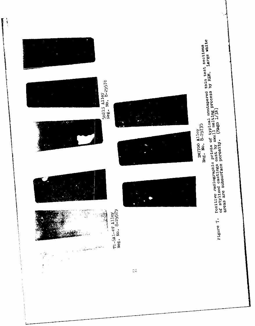
induction melting process at REM.. . . . 197 Positive radiographic prints of typical nontapered
thin test sections of stylized castings by skullmelting process by REM . . ... ...... ... 22
8 Positive radiographic prints of typical nontaperedthin test sections of stylized castings cast byinduction melting process by TRW .... .. ... 23
9 Positive radiographic prints of typical taperedthin test sections of stylized castings cast byskull melting process by REM . ..... . . . 24
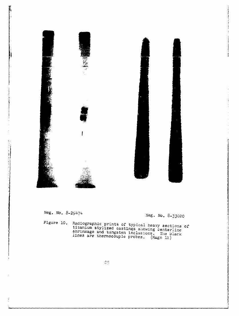
10 Radiographic prints of typical heavy sections oftitanium stylized castings showing centerlineshrinkage and tungsten inclusions ..... ...... 25
11 Room,1 temperature uniaxial tensile properties ofthin sections in titanium alloy stylized castingsproduced by the REM skull melting process . . . 39
3,2 Room temperature uniaxial tensile properties ofheavy sections in titanium alloy stylized castingproduced by the REM skull melting process . . . 40
13 700F uniaxial tensile properties of heavy sectionsin titanium alloy stylized castings produced bythe REM skull melting process . . . . . . . . 41
14 Typical examples of defects in cast titanium alloysdetected by radiographic examination . . . 50
15 Typical as cast surface of Ti-6AI-4V alloy thintest sections cast by the induction meltingprocess. ... -.. 2
16 Illustration of surface effect'relative toheat.treatment of Ti-6A1-4V alloy castings in STAcDndition ...................... 53
17 Typical structures of annealed Ti-6AI-4V castings . 5418 Typical microstructure of Ti-6AI-4V castings in
the STA condition ........... . 5519 Typical microstructure of 5621S castings in the
STA condition ..... ......... 5620 Typical microstructure of IMI 700 castings in
the STA condition .......... ............ 5721 Typical micrnstructure of Beta III castings in
the STA condition.... . . . . . . o...... ......22 Cooling curves from titanium stylized castings
produced by the REM skull melting process . . . . .
vi
F IGtGUE DESCRIPTION PA GE
23 Composition of low cycle fatigue properties ofcast and wrought Ti-6AI-4V (STA)... . . . . . . . 65
24 Cast TI-6A1-4V strain-life plots-roomtemnerature . . . . . . . .
. .-A.. . .VI? .1 14 Aarid 7 r .l .l. . . . :26 As-cast TI-6AI-4V alloy Impeller . .. .............. 7027 Sketch showing location of tenslle'and'metallo-
graphic specimens from Ti-6AI-4V skull melt
impeller casting .............. ................ ..7128 Ti-6AI-4V cast Impeller showing FPI Indications . . . 7529 Ti-6A1-4V cast impeller showing FPI indications
in the airfoils . .................... ..... 7630 Ti-6Al-•;V cast impeller finish machined for
spin testing. . .. * ' .* ' 7731 Overall review of a cast'Ti-6Ai-4V'impeller
after spin test . . . . . ..... ....... 7832 Fractured airfoil showing heat tinted area,
indicative of crack existing prior to heattreatment ............ . . . . . . ...... 78
vii

LIST OF TABLES
TABLE DESCR IPTI'ON PA GiS
I Basic Test Plan . . .. . . . .... 4II Characteristic of Sel..t....... .!ii Summary of Visual and Radiographic Evaluation
of Titanium Stylized Castings ......... ...... 20IV Chemical Analysis of Titanium Castings Cast by
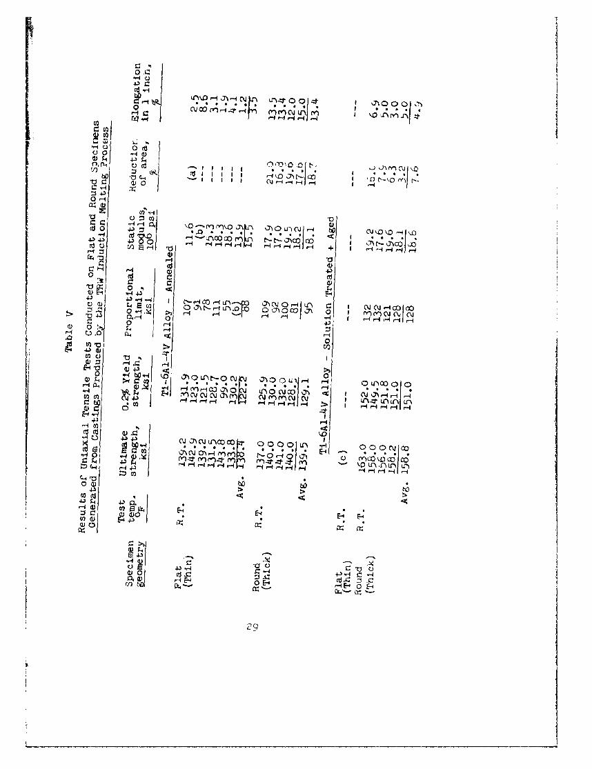
Induction Melting and Skull Melting Processes . 2V Results of Uniaxial Tensile Tests Conducted on
Flat and Round Specimens Generated From CastingsProduced by the TRW Induction Melting Process . 29
VI Results of Room Temperature Uniaxial Tensile TestsConducted on Flat and Round Specimens GeneratedFrom Castings Produced by the REM Skull MeltingProcess . . . . ........ .......... 31
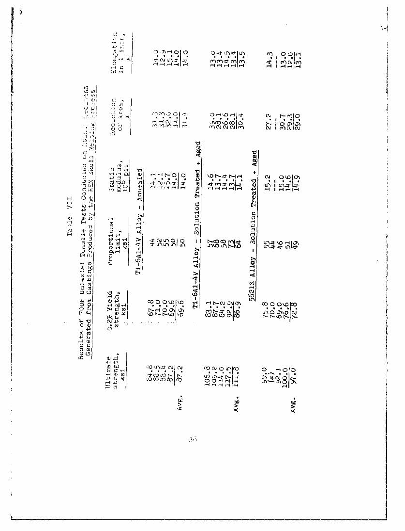
VII Results of 700F Uniaxial Tensile Tests Conductedoa Round Specimens Generated From CastingsProduced by the REM Skull Melting Process . . . 3C
VIII Effect of Specimen Geometry on Room TemperatureUniaxial Tensile Properties of SpecimensGenerated Prom Solution Treated and Aged SkullMelt Ti-6AI-4V Castings . . ..................... 43
IX Comparison of Average Tensile Properties of Castand Wrought Titanium Alloys .. .. ..... . . . . . 44
X Room Temperature Dynamic Modulus of Elasticity ForSkull Melt Stylized tastings ..... . . 46
XI Cantilever Beam Fatigue Test Results (FundamentalMode) for Skull Melt Stylized Castings. . . . .. 47
XII Record of Ballistic Impact Tests on Thin0.055 -0.060 in. Titanium Alloy Specimens. . . 49
XIII Grain Size Determinations for Titanium AlloyStylized Castings . . . . . . .......... 59
XIV Summary of Cooling Curves Obtained FromInstrumentation of Titanium Stylized Castings . 60
XV Comparison of Strain Range to Cycles for Castand Wrought Ti-6AI-4V (STA) ............... 5
XVI Summary of Low Cycle Fatigue Results For CastTi-6AI-4v (STA) ... . . . ... ,.
XVII Room Temperature Tensile Properties of SpecimenGenerated from Ti-6AI-4V Impeller Cast by theSkull Melting Process ......... .............. 72
viii

IiiA
BLANK PAGE
I (J
.4
r13iECTION I
INTRODUCTION
The systematic use of any rnew materlal ,. oauced into usaoleforms for gas turbine engine conqonents requires a sne'ol'I.cpth o. devIojuptrit, ani arai:sis to ensure functionalintegrity.
A major problem whiicin largely preventeu use oi tiL tniumcastings was mold reaction 'with the liquid titar~unim alloy.Development of a snell molding method Incorporatingrefractory metal impreinated mold surfaces has beenacccmplished. Thus, attention can now be directed towarddetermining the capabilities of the precision investmentcasting process to make complex shapes to finished dimensions,the suitability of specific alloys for such castings, and tnemerits of various melting practices. The overall goals of analloy dev(:lopment program are to provide titanium castingalloys matched to specific casting processes for a broaaspectrum of sizes and structural requirements - all with"satisfactory' surface finish and minimum weld repair needs.The overriding principle is the levelopment of a competitivclývpriced systermI satisfying the range of structural needs.
This problem deflnition program was conducted to determinethe need for new alloy development by first appraising thesuitability of presently available titanium alloys, withrespect to castability and end-item casting performancepotential, for application to complex gas turbine enginecomponents. Emphasis was placed on requirements of highspeed rotating elements, e.g., centrifugal impeller, withthin high aspect ratio elements.
The alloy and end-item casting goals were:
9 Castability that permits the filling of wcb sectionswith aspect ratios of - 20:1 when abutted to amassive primary section.
* Static strength of 130 Ksi ultimate (normalized totne density of Ti-6AI-4V) with an elongation of10% and a reduction of area of 10X.
• Freedom from internal shrinkage, laps, and hot tearswhen matched to specific casting and molding practices.Specifically, radiographic quality at least equal toASTM E192, Grade 3 in thin sections.

This report describes work performed during the contract.It includes a description of the experimental procedures, adiscussion of the results. concluninnR e-nd re~nier4^.

SECTION II
EXPERIMENTAL PROGRAM
The program was divided into two phases: I - CommercialAlloy Screening and Property Eva]uation; and II - OptimumAlloy Evaluation. The basie test plan is shown in Table I.
2.1 PHASE I - COMMERCIAL ALLO'Y CHEENING AND FROTERTYEVALUATION
2.1.1 Coimmercial Allo_ for .-jtudy
The four commercially available heat treatabletitanium alloys, normally used as wrougnt products,selected for initial studies to determine tneircharacteristics as casting alloys are listed inTable II.
Table II
Characteristics of Selected Titanium Alloys
Strengthi at temperature
Alloy Structure Ambhen ElevateO
Ti-6A1-4V + ÷ Medium LowIMI700 + 0 High Medium5621S + fi Medium HighB12OVCA High Low
These alloys represented a wide range of compositions,as well as a wide range of strength capabilities fromambient to elevated temperatures up to 700F.
Early in Phase I, alloys IMI700 and BI2OVCA werereplaced with Beta III alloy. Newly published dataindicated that Beta III had hIgher potential thanthe replaced alloys with regard to achieving th-eprogram goals.
The alloys were purchased from the following vendors:
Ti-6AI-4V; Harvey Aluminum - Heat No. 32142466Ti-OA1-4V~a): Titanium Metals Corp.- Heat K232256213 Reactive Metals Inc. - Heat No. 29420
5 6 2 1••a): Oregon Metallurgical Corp. - Heat No. 5174-DIIMI7O0: C. Tennant Sons and Co. Heat No. A74ý)4B12OVCA: Titanium Metals Corp. - Heat No. K2461Beta III: Colt Industries Crucible Inc.: Heat No. K5Qhi
(a) These heats were required to complete the program
following Phase I mid-course redirection.

n -41 .
C'4-) I I I
cll
SdJ
4C4
C~CD
I- l:OI I I
m- 00c%L4 43
I H ) .
\U - - d 4) - -*04 N4 0 ( 4)a
dir HIu a)
Io C-4

-1
2.1.2 Test Casting Confýiuratlon
A stylized casting configuration, shown in Figure 1,was designed to (1) nAnf• •pcm^j..s f.cr . oRaphicevaluation and mechanical property tests, (2) obtaincomparative evaluations of alloy castability, and (3)determine eff t of casting practice anu thermaltreatments on castinE. dirner,3lons. Tnht structure andproperties of this universal shape we.'e expected toclosely represent those In critical soctioni ofvarious turbine engine comp,.Anents, e.g., a compressorimpeller web (heavy section) and vanes (thin section)as well as a compressor vane airfo!l (thin section).
The wax pattern die for the sty1 .zed specimen, builtby Detroit Diesel Allison Exp .-imental Manufacturing,contained inserts which permitted fabrication ofpatterns with thin section thickness of either 0.060 or0980 in, Originally the design did not incorporatea taper in the thicicness direction of the thin testsections, but, as described in Section III, the taperwas later required to enhance thin section quality.
2.1.3 Tnstruinentatiori
Test casting molds were instrumented with thermocouplesto permit evaluation of the interrelationships betweencooling rate, mechanical properties, grain size andother microstructural features. The temperatures ofboth the shell mold and the actual casting, in botnthe thick and thin sections, were monitored on alimited number of castings to establish a correlation.It was intended that once the correlation betweenshell and cavity had been established, only the shellmold would be instrumented. A mold instrumentationschematic is shown in Figure 2. Ta sheathed W-W/Rethermocouples were used in the cavity and bare W-W/Recouples in the shell. The cavity thermocouples wereinstalled just prior to casting. Thermocouple outputswere recorded by high speed oscillographic devices.
A preliminary test of a 0.014-in. dia. Ta sheathedW-W/Re thermocouple, in contact with molten Ti alloyduring casting and alloy solidification, was conductedto determine test efficiency and thermocouple life.A thermocouple was inserted into the cavity of agraphite mold and exposed to a molten charge ofTi-6Al-4V alloy. The thermocuple output was recorded

-44
-- 44
0
00
4J.
'-4
V) 0
F-4-

~4 0QH 0
0
0000
% Ci2IL C))
C)rIaEQ
4. 4.. -4 4
C.) -- -c.!cd ) > 0* 4. ) 4.)
0'. 4 cr1Ct
w) 43
CL -2) W.42 cr3 0 4 (fz. .'4~ 4 .HI 4)0 %~ :3 4J 43- e4*ý
-~t C d 4
4-)~~ 04-)c:
ONC. 4- I 4-3 .)
4. E r-4E-4) 4-)N -1-A 1
(1) 0CCr. E
C EC)2
d) 04) :ErH

on a fast response X-Y recorder, using parametersof time versus temperature. Sectioning of the ingotand resultant microexamination of the thermocouplesheath revealed only minor surface effects due toalloy diffusion. Thermocouple integrity was inviolateand considered satisfactory for recording ofsolidification curves. W-W/Re bare wire wasencapsulated in a trial mold and exposed to a 3000Ftemperature in a laboratory furnace. Results ofthis test indicated accurate recording of shelltemperatures and it was thus concluded that anunshielded thermocouple could be employed satisfactorily.
2.1.4 Melting and Casting Processes
Both indu.-tion and consumable electrode skull meltingprocedures were used at the start of the program. Areview of early Phase I castability data indicatedthat the program goals could best be achieved by skullmelting alone. At that point, induction melting waseliminated from the program,
2.1.4.1 Induction Melting
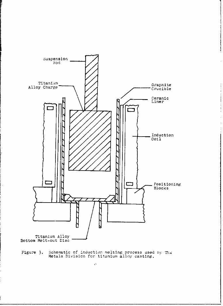
The induction melting practice used by TRW MetalsDiv. can be described with the aid of Figure 3. Aspecially designed induction coil is placed aroundan expendable crucible as shown. The bottom of thecrucible contains a titanium alloy plug of the samecomposition as the main charge. The metal chargeis mechanically suspended and does not contact thegraphite crucible wall until completely molten andthen for only a few seconds. A specially programmedpower application is used to heat the entire chargeto within a few degrees of the melting temperature.Power is then increased substantially to cause totalmelting within a few seconds. Almost immediatelythereafter, the bottom plug melts and the moltencharge is automatically tapped through the bottomof the crucible. The degree of superheat obtainedis determined by the size of the metal plug used.Reproducibility of the pouring temperature isexcellent, typically + lOF. Melting and pouringrates are also remarkably reproducible. A vacuumof 10 microns or less is maintained throughout themelting-pouring cycle. The chamber is back filledwith dry argon about 2 minutes after pouring toreduce total cycle time.
Ti-6A1-4V alloy castings melted by this method andpoured in graphitized ceramic molds have consistentlyconformed to AMS 4928 composition requirements,
8
SuspensionRod
Titanium GraphiteAlloy Charge Crucible
CeramicLiner
InductionCoil
EJ Positioning
Blocks
Titanium AlloyBottom Melt-out Disc
Figure 3. Schematic of induction melting process used by -m,Metals Division for titanium alloy casting.

provided that carbon content of the ingot wasauitably low, e.g. e0C0X5
The i.nduction process provides molten metal atcontrolled superneat from very rapid inductionmelin-•,1 . .whiz c s cr o gl =...• preven-t
1'[c;atnt contamination of molten t'itanium by
the reiatively inert graphite crucible. Forexample, it is possible to i;ielt and pour an eightpoun(I charge of titanium in approximately fourminutes. Of this four minute time, the charge ismolten less than one minute. The very fast meltingcycle, combined with levitation effects on thecharge, produces molten titanium of aircraft quality.
2.1.4.2 Skull Melting
The skull melting process, used by REM MetalsCorporation, is accomplished in a consumable electrodefurnace. The chamber contains a sodium-potaassiumcooled copper crucible in which melting is accomplished.The melting stock is a large electrode. An arc isstrunk between the tip of the electrode and the coppercrucible, thereby causing titanium to melt from thetip of the electrode and to form a molten puddle inthe crucible. Since the crucible is cooled, titaniumimmediately in contact with the crucible wallsfreezes forming a 'skull". In effect then, themolten material is contained within a crucible ofitself or of the same alloy composition. Thiseliminates the possibility of contamination. Whenan adequate amount of metal qas been melted to fillthe mold, the power is turtoed off, the electroderetracted from the crucible, and the crucible turnedto pour the metal into the mold. Usually 85% of themetal is poured and 15% is retained as "skull". Avacuum of 10 microns or less 4s maintained throughoutthe melting-pouring cycle. f,.lds are held in thevacuum after pouring until the temperature drops toapproximately 400F. Titanium alloy electrodes arepurchased from commercial alloy supp2ler•r as doublevacuum melted forging stock. Thus, t?.sncontains triple vacuum melted alloy.
2.1.-4.3 Molding, Insulation, Preheating, and C' -
Uninsulated, tungsten metal face coated ceramicshell molds, of the same formulation and thickness
P:

were used through ut. All were prepared by REMMetals Corp.(1• 2)
A mold preheat temperature of 700F was used topour skull melt styizrAd eastings. Tniz tcmpcratarewas established during a General Motors fundedprecontract program as suitable for achievingAST... Ellr _G 3 G' diorapnic quality in thinsections of Ti-6AI-4V castings. Grade 3 iscommensurate with Detroit Diesel Allison require-ments for the steel version of the impellercomponent. These parameters were then used asthe base line parameters for the other alloys soas to have a direct comparison for castability.A higher preheat temperature, determined byexperimentation, was required to avoid severemisrun of thin sections in castings poured by theinduction melting practice.
All casting knock-out and clean-up operations werepreformed by REM Metals Corp. Clean-up consistedof grit blasting with garnet sand followed byimmersion in a hot caustic salt bath (Kolene, DGS).
2.1.5 Screening Tests
2.1.5.1 Castability
The castability of the selected alloys wasdetermined by adjusting the high aspect ratiocastabi2ity sections of the stylized casting soas to produce incomplete filling by the base linealloy Ti-6AI-4V. The other alloys were then castinto the stylized configuration under the samecasting parameters. The degree of fill and generalquality of the castings was then used as an indexof the individual alloy's castability. Radiographic,fluorescent penetrant and visual inspectiontechniques were used to determine the quality ofthe castings.
(1) U.S. Patent No. 3,422,880: Method of Making InvestmentShell Molds for the High Integrity PrecisioinC astIng ofReaCtive and Re fractory Metals (hEM Metals CorporazYohT.
(2) U.S. Patent No. 3,537,949: Investment Shell Molds forthe High Integrity Precision Casting of Reacti-•-•dT---Refractory Metals and Methofds for th-er-nufacture(REM Metals Corporation).

2.1.5.2 Dimensional Stability
It was intended and would have been desirable tomeasure dimensional effects of heat treating onthe thin test sections. However, the need toobtain flat specimens for mechanical tests resultedin a decision to remove the thin sections from theheavy sections prior to heat treatment. One wholecasting was solution treated and aged. Measurementsbefore and after heat treatment showed no distortionaleffect of the heat treatment. Thus, dimensionalinspection of stylized castings was deleted.
2.1.5.3 Tensile Tests
Room temperature tensile properties were determinedfor thin and thick sections of the castings. Thethin section specimens were flat samples whilestandard 0.252 in. diameter specimens were generatedfrom the thick sections. A minimum of six thinsection and four thick section tensile tests wereconducted on each alloy-casting vendor combination.Measured values were ultimate strength, 0.2% yieldstrength, proportional limit, % elongation, % re-duction of area and elastic modulus.
Elevated temperature tensile tests were performed at700F on thick sections of the castings, using fourspecimens for each alloy-casting vendor combination.
Both room and elevated temperature test specimensfrom thick sections were run using a Riehle 60,000 lb.capacity unit with a strain rate of 0.005 in/in/mmnto the yield point. Strain was then increased toapproximately 0.10 in/in/min, producing failure inless than 1 minute. Extensometers were used forstrain measurement.
Thin section tests were conducted using an Instron10,000 lb. capacity unit with a strain rate of--0.020In/in/min from start to failure. An istron extensomete-with a 0.5 in. gage section was used for strain measure-ment. FlatO.250 in. width byO.05-0.O6in. thick by1.125 in. length reduced section specimens were used.
2.1.5.4 High Cycle Fatigue
Thin sectionE of the castings were evaluated forroom temperature high cycle fatigue properties byvibrating cantilever beam specimens in the fundamental
12
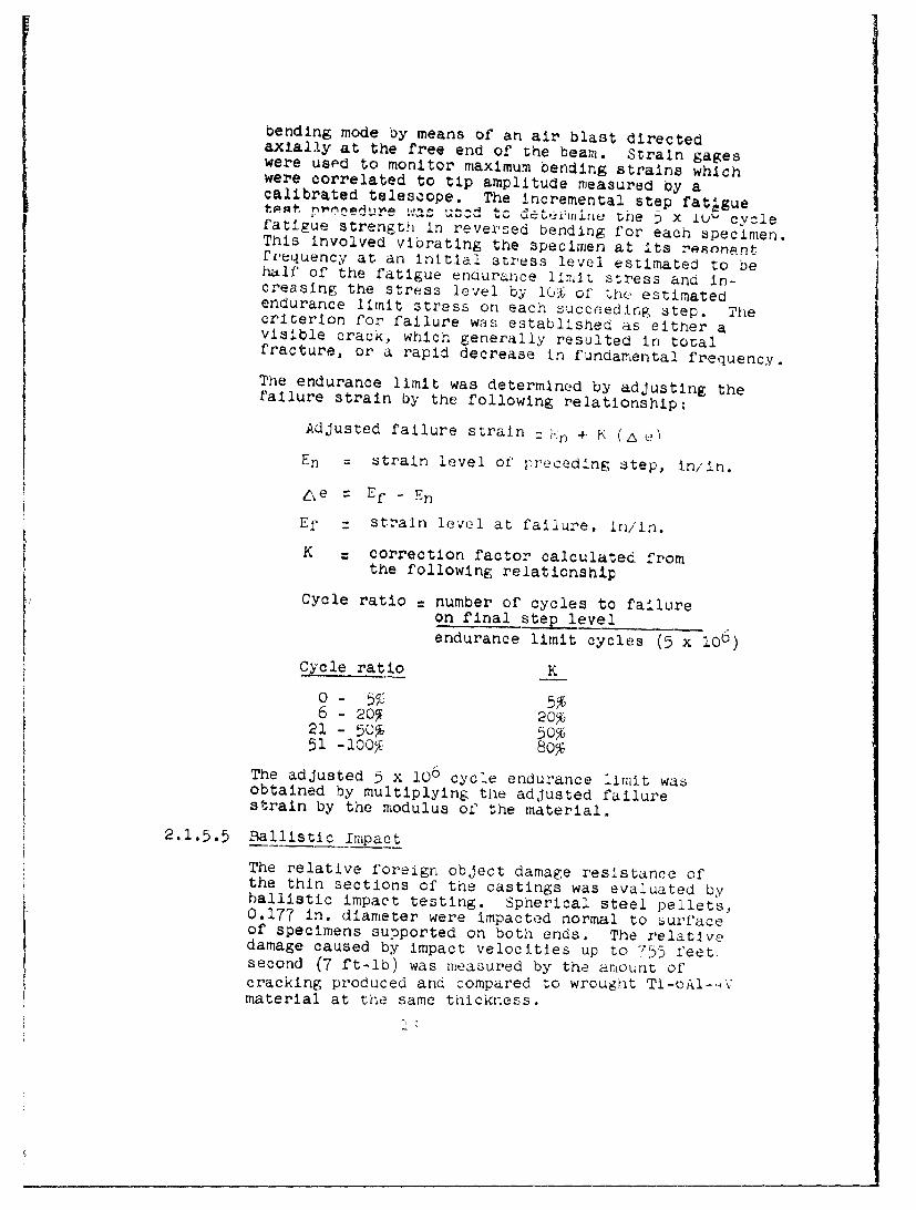
bending mode by means of an air blast directedaxially at the free end of the beam. Strain gageswere used to monitor maximum bending strains whichwere correlated to tip amplitude measured by acalibrated telescope. The incremental step fatIguet •t ........ .w tc t=•'w • the ; x Lu- cyclefatigue strength in reversed bending for each specimen.This involved vibrating the specimen at its resonantfi'equency at an Initial stress level estimated to behalf' of the fatigue endurance limit stress and in-creasing the stress level by 1Q% of tQhe estimatedendurance limit stress on each succeeding step. Thecriterion for failure was established as either avisible crack, which generally resulted in totalfracture, or a rapid decrease in fundamental frequency.The endurance limit was determined by adjusting thefailure strain by the following relationship:
Adjusted failure strain : !':n + K (• ?)
Fn = strain level of preceding step, in/in.
n e =Ef - En
Ef :strain level at failure, In/in.
K correction factor calculated fromthe following relationship
Cycle ratio = number of cycles to failureon final step levelendurance limit cycles (5 x 100)
Cycle ratio -K
0 - 55, 5,16 - 209 ~ 20,%
21 - 506 50%51 -100*% 80%
The adjusted 5 x 10⁶ cycle endurance limit wasobtained by multiplying the adjusted failurestrain by the modulus of the material.
2.1.5.5 Ballistic Impact
The relative foreign object damage resistance ofthe thin sections of the castings was evaluated byballistic impact testing. Spherical steel pellets,0.177 in. diameter were impacted normal to surfaceof specimens supported on both ends. The relativedamage caused by impact velocities up to 755 feet,second (7 ft-lb) was measured by the amount ofcracking produced and compared to wrought TI-oAl-.Vmaterial at the same thickness.

2.1.5.6 Microstructure
General metallographic examination was made of thethin and thick sections to correlate grain sizeand phase distribution with mechanical propertiesand/or solidification rate. In addition, surfacecontamination, due to the casting process, wasevaluated on thin and thick as-cast material byelectron microprobe analysis.
2.2 PHASE II - OPTIMUM ALLOY EVALUATION
2.2.1 Low Cycle Fatigue Tests
The results of the screening tests were reviewed todetermine the ranking of the alloys produced by theREM casting process. Ti-6A1-4V was selected as thealloy with the best overall combination of castability,quality and mechanical properties and was cast intoten (10) additional stylized test samples for low cyclefatigue testing. Isothermal, strain controlled lowcycle fatigue tests were conducted at room temperatureand 700F on specimens removed from the thick sectionof the test castings. Seven specimens were tested ateach test temperature in order to establish strainrange vs cycles to failure relationships. Plots ofplastic, elastic and total strain range as a functionof cycles to failure were generated for lives between1 and 10,000 cycles.
2.2.2 Component Casting Evaluation
The alloy selected for low cycle fatigue evaluationwas also cast into the T63 impeller configuration,using the optimum casting process. Two impellercastings were made. A photograph of the subjectimpeller is shown in Figure 4. This part is typicalof complex configurations of highly stressed dynamiccomponents which will benefit technically and cost-wise,when produced from lightweight, high-strength corrosionresistant titanium alloy casting.
Radiographic, fluorescent penetrant, and visualinspections were performed on the as-cast impellercastings and again after heat treatment.
One impeller casting was sectioned for tensileproperties and microexamination. Room temperaturetensile tests were conducted on the heat treatedcastings for comparison with the screening testresults. Metallographic studies for surface

Figure 4. TD3 impeller castinf (I•a; IX) Neg. No. 8-2606S
.I

conitamination, general quality, grain size, and'nicr'ostructux-al characteristics were made on thehfxet. treated casting.
Trie second impeller casting was spin tested todCstictl,, ~L voiuri temperature and failure
:I naur1 was performed to determine mode of'%Iilure.

ISECTION III
RESULTS AND DISCUS&LON
3.1 PHASE I - COMMERCIAL ATT,nV ..- ',., I
EVALUATION
3.1.1 Castabi1 4 °l
Castability, as determined by visual and radlographicexamination, of the stylized specimen cast in theprogram is summarized in Table III.
3.1.1.1 Visual Evaluation
Based on the visual appearance of the castabilitysections and the thin test sections, there was noapparent difference in the castability of TI-6AI-41V,5621S, IMI700, and Beta III alloys when cast byeither the skull or induction melting proce3ses.
Representative skull melt castings of nontaperedthin test section configuration from REM are shownin Figure 5. The same variability in degrees offill of the 0.035 in. castability sections was notedboth between castings of the same alloy and betweencasting of different alloys. This was also true forspecimens cast with the tapered thin test sections.
Representative induction melt castings of nontaperedthin test section specimens from TRW are shown inFigure 6. Again the degree of fill of the castabilitysections did not appear to be alloy sensitive.
The data of Table III indicate that skull meltingwas more successful than induction melting withrespect to producing sound thin test sections. Apossible explanation for the inability to consistentlyfill the mold when using the TRW bottom pour inductionmelting process is that the coldest portion of themelt (the last of the charge to melt) enters the moldfirst and is solidifying before completely fillingthe cavities. One casting with 0.060 in. thin sectionswas poured at TRW using a very high 1500F mold preheattemperature. Two coats of the prime dip were employedon this mold in order to prevent pernetration oftitanium to the ceramic backup shell. Again, thethin test sections did not fill completely. Therefore,additional castings from 'MW used the 0.080 in. insteadofO.060 in. thin test sections.

D621Z3 AlloyNeg. No . 8-29553
S'..
I Ti-1K 1-00 Alloy
Neg. No. C-29'7'10
-- Eu T' tanluri alloy ized casting .Produced by-i~ll menting pr oce 6s atý KEN (Mag ln /3X).

Nee~. No. 6-K2j+4(7
Fik:La'e c. Titan-lium ailov st A ,'ica (xŽ pciUCed

: j ri d lc
i'U4 0 00 0 0 0 0 fu (D 11Oc0, z z >4 P- .
I, -- I 'c T3 10
r-.~ c.0 0DC 0 0 00 00 c0 0~ dC0 0 0 3 0 0 0
0HH
0 0 qL44 0r.0 04 a~ H-- -0 4. 43 q . 0
V " -H a I - C4 -1 0-4 0) -4 q j )
C: C; C:6M.
4-3
4-3Hc

3.1.1.2 Radiographic Evaluation
The thin test sections were removed from theheavy section of the stylized specimens priorto radiography to present an optimum situationfor X-ray inspection.
In general, radiographs of stylized castings, withnontapered thin sections, shuwed thin sectionimperfections corresponding to ASTM E192 Grade 4or higher regardless of casting process. This wasnot commensurate with requirements for highlystressed rotating components. Present X-raystandards for impellers (Detroit Diesel Allisonspecification EIS 675-7) covers precision castingsof nickel, iron and cobalt base alloys. Thisspecification, referencing ASTM E192 radiograpnicstandards, requires a grade no worse than 3 on thinsections. The imperfections, as shown in Figures7 and 8, appeared as dendritic/sponge shrinkageand gas porosity. The spots of porosity in the3kull melt castings appeared to be smaller andmore evenly distributed than those in the inductionmelt castings which were more gobular. Large areasof porosity evidenced by the white spots, areplainly visible in Figure 7. These areas werevisible by X-ray only. Visually, the sectionsappeared to be structurally sound. Sectioningof these areas showed a hollow vane effect wherethe alloy had solidified at the mold walls butfailed to fill '.he center portion.
Subsequently, a 1.5 degree taper was incorporated oneach side of the thin sections to aid in feedingduring solidification in order to reduce oreliminate the dendritic type shrinkage. The originaldesign, meant to sort out subtle differences in thealloys, had served its purpose. In general, thetapered thin sections of all three alloys, Ti-6A1-4V,
* 5621S and Beta III, showed radiographic quality thatdid meet or exceed the grade 3 standard. Represen-tative radiographic prints are shown in Figure c.No one alloy was significantly better than any other.
The thick sections of the castings were generallysatisfactory. The representative positive printsshown in Figure 10, illustrate the general typesof defects noted, i.e. centerline shrinkage andtungsten inclusions. There were a few incidentsof isolated gas porosity not associated with thecenterline pipe. The gas porosity and inclusions
w44
-444
0 bO
cJD
" N-
I .
00
z -4
m~--
r-4 ti,
0Lr0
4)

Ti-6AI- 4V AlloyNeg. No. 8-29472
56213 AlloyNeg. No. 6-33025
Figure 8. Positive radiographic prints of typical nontaperedthin test sections of stylized castings cast byinduction melting process by TRW. (,agn 1X)

0 bO
crz
4-)
00
*H 4)ý
02 r
L4Cc,
0J- 4)
C4)
ho
II
"C4A6I i
Neg. No. 8-29474 Neg. No. 8-33020
Figure .0. Radiographic prints of typical heavy sections oftitanium stylized castings sziowing centerlineshrinkage and tungsten inclusions. The blacklines are thermocouple probes. (Magn IX)

do not reflect on an alloy's inherent castabilitybut are related to routine foundry problems withrespect to fabrication of high integrity shellmolds.
j. Heat Treatme~it
SThe stylized were neat treated priur tomechanical testing. All were solution treated witha protective atmosphere of argon. However,approximately•OO5 in. stoex was removed from each
sile of the thin test sections prior to specimengeneration for mechanical testing as a precautionarym,ýeasure in case some surface contamination hadoccurred during heat treatment.
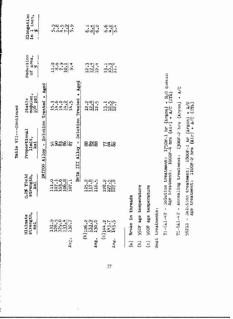
Tie thermal treatments employed were as follows:
ri-6AI-4v - Solution treatment: 1750F-1 hr. (Argon)S~H20 quench
Age treatment: OOOF-4 hr. (Air) + AiC(STA)
TI-6AI-4V - Annealing treatment: 1300F-2 hr.(Argon)+ A/C
5621S - Solution treatment: 180OF-1 hr.(Argon) +A/C
Age treatment: 11QOF-2 hr.(Air) t A/C (STA)
IMI700 - Solution treatment: 1550F-1 hr.(Argon) + A/CAge treatment: 930F-24 hrs.(Air) + A/C (STA)
Beta III - Solution treatment: 1350F-15 min.(Argon) +
H20 quenchAge treatment: 950F or 90OF-4 hrs.(Air) +
A/C (STA)
An aging temperature of 950F was utilized for theinitial Beta III tensile tests, based on therecommendation of REM. The test results indicatedthat a lower aging temperature, e.g., 900F, mightprovide higher str'ength. Thus, the lower agetemperature was used for the remaining Beta IIItesting.

3.1.3 Physical and Mechanical Properties
3.1.3.1 Chemical Analysis
Chemical analyses were determined for castingsof each vendor-•1•y cob.atoi......... .... _- ,u. ý L epresentative
analyses are listed in Table IV along with thedesired end-item and starting material ingotarnalyses. Skill melt castings conformed essentiallyto prescribed aims. Castings produced by theinduction melting process were slightly higher inbulk carbon content due, probably, to pick-up fromthe graphite crucible.
Electron microprobe analyses were conducted ontransverse samples from the thin sections oftypical stylized shapes in the as cast condition.There was no evidence of tungsten mold materialdiffusion or other, reaction in or on the castingsurface. The microprobe analyses did not includeevaluation of interstitial elements.
3.1.3.2 Tensile Tests
All tensile specimens were radiographicallyinspected after machining. The induction meltspecimens (TRW) met ASTM E192 Grade 4 or betterwhile the skull melt (REM) specimens met Grade 3or better. This quality difference is reflectedin the lower ductility of the thin induction meltspecimen s.
Results of tests on stylized castings of Ti-6A1-4Vand 5621S alloys produced by the TRW inductionmelting process are listed in Table V. Thin sectiontensile data are given for only annealed material inthe Ti-6A-A4V alloy. No solution treated and agedthin section specimens of Ti-6A1-4V alloy weretested due to poor structural integrity. No thinsection data were obtained for 56213 alloy aue topoor castings fill. Both room temperature and700F tests were conducted on specimens generatedfrom thick casting sections. Strength of thin andthick sections were comparable although ductilityof the thin sections was lower.
Table VI lists room temperature data on thin (flat)and thick (round) section tensile specimens fromcastings produced by the REM skull melting practice.Elevated temperature data (700F) are given inTable VII. Tensile properties of skull melt castingsare summarized graphically in Figures 11, 12, and 13.

(J'u'c0 0 000 0, pq I h -IP4
0 -n .C\ (Y) n-N 0 \Jx()C0 0n (YI-1( QQr O jC~
000 -~w 000
t ~ ~ o~~ LX'L L1 0U) C I r0000-4Q~ I 0e-~ 000
coo lIr lii 0 CnoLQ liii
I~, cmn~o'O(J 0' 000 94 ti N" Lil M t i i
43 I i IV'2 " *Q IN -: %1 4 j(d 43
co1 C- I 41
I) 4I Y. %,n ::rt--.c
Ch L~%oo
Cl iiiico .(caw 41 0 Lr0 000n
.- ~0 000o0 Gc0000 0 0000000a H000
04-
xC. na 00o o
* 4ý -4 4Q I
Cd .4
0Sr 0 O.$j o00 00 080 A 0 8
4~0 00-:C ~ y I (NJ ) lH
H .'C. I I y
tor w
d) gdf 4-a4ol
.0 00
0)0 '
cd 0 0 U' C\ J
-to U .~ V)~c co a~o t-HT
H4-)4-
0 *d
0
OF- HE) t0 E-4 )No'4Jz t-r-In OT) coO-

4J
C.,
J~hd.-I--.-. 0
.74 -r
T4.3
0 -4-
ii n i I)oic)tn o0 ' 4zI~ tQzrn 0t
o nh
60 C -,- 1 I \ , o O4- (0 O
QrL~ 0d 0~' od 4- r-4
C)~r- j I 00 rqN~ '-d (/1 4 ) r
HD ci) (1 * :\J,.t :0 T ONO 43 M4-
re) -: re) -*t 00 03 co *.CC'i O~d~t--A ,-i ri r\- -A4\ r-j 4HO.i H iC 3Cr- 4) 41~
4~~ý 0rIH C4
'-I U (U0 c ~ C.J~
4-').'~~~~~C '-4 53J& ~z 4-)1 C\ 4 0 -) (
~~tlbi(---4- E-4 -4 (3) * . * * *o 01 c
co 0 4 J-Io 4.) *4 M I0
Q) C_( 0C. H
~~ -A ~~E-i-4- 43 -) - c.1) 0 1
C) t.-4 (d a

wI10k
o, LO%(rOD~ 0HO fnu'~-'' '- rU)Ln0L L)ý
F-4 r-4H r0
Q I 4Lii: (X ;It00 ;- rI
H C~'/~ -H4) 0 -
0) Qii'X 0 -
;.4 CO-4
H a)
0 " 'XrHqH-qr4,-l 4 H rq HI I q HHHHH-H H- -
OH 0
C, '3) 0
0 d) 0 f ItN Ol l0 Lf\$.9 )ýaý lO I I\HHrez H0 QHH %-4 r-H-4 H A4' %lý,:
0~ ;;a 4 . )t ~ )AC ýc- -

ly) 1 -) Cn-t J\OTOV* 4'1 (In MI r- 4 JliH I' n
~--1 II ,-4 t-4 o-4 -4
-I r- \jH -
-*-~ +
-I "1 % U- xC
A .'.I -4 0di r-4I~ 0 -H4 O-I .-4 4-1~ Co:t 1",'J 1.lJ
0
H I o - r- 'r- -4 - -1r-4 -4 I ýl -4 -1 n - - - -I c- rQ-A r-4
k:) LI,)In C 0 I -- t Q ---I t- N ,-D .-4ý rIt
(1) C -c" ý 10U0 jnL- nus'o I) N()-tr (I n( Y 1
H>
01 CLýz V
~~~)0I ~ ~ ~ ~ ~ - E-4 0*(1rI~ E-4H0 U CJ~C\OO)

W "4
11111 MI I-
V ;_4
wOrtcv ~ 0 LL~L'
I * * * '~ * * * * 0) * * *W
4)b--- * C Jfo~ ~A H HH + 3 I H H ~ H.H H
.1-4r-4 kl v zt -ýt nrý t: )
W ; 4 1
000) 0
0 -, -440- %- N OHj` ' " " 1
0 -H W 4- - - HHHrir
a 4 H
0 H
1) 4.3 C/) -zt 1 m N Oa% HH CýJ' H no -.tO0 c
c02 N\J I;0 c-Ol\~ t- O 0a\4 4 -ir- H rq I 't-I,-H .0HH n H-t-
43~j4.)
11000 C-Ch0j Hh r.OCJH
r-4 4a 3 - -H H HH '-- HHHHH rqfHHR-H H- - -
ID V)
V-4S
4-3~4.).dC44.-,0 c0(
HE-40 HE-r~'- ýr-

rr
:111() t LJ) *r if :t It :
C..)
WC~~U I -i
C1 0 '
'~~~'~t '0 4-3'W0 2 r~J l(~~
:5 00 C
1- i 0 d-4 C4 00~ %.)Oa0- 0 co 0,3
0,-1 rlr4Ii) 4-0
Q
004-1 f4)4.)CI
F-'b -4.' 4.) 0 4.) .
0 -1Ct.0 - ) N C: o bHz '4C'0 1no 0LC 4 0
(1)~~a~ In(YI; .3 b
,--14.) -4 r 1-1 r-q4.3ZU a))
EXý coL~ c
H H Hý pq- H H C, F,,,4.
0 E . ah) A:) 0 V-- l0 4 A ) V

0 0
0E -:
v; +' 60 '-Z 0
60 44. L
C.) r-4 N'J
S.- :4--
coH
.0 -40
4 J. . 0 cU O N~
c4.) 0) 0 4.3*
04 ~4 - 4- 0 4
%-4:4 ~ -4 .- +a C
0 o %-4 060 Q.J /) 4c 4. 0 bo~
0 I H
4.~ *~: ~4.)4J E4-4 L
435
Lp
(n (Y ) N- Lr~j~r rn NIrn CMQ~
C) "- E. +I*. . . I .m--t (\jtf 4 --- 4n-te ) U I --,t'o C HHHf F- H-f r1- Hlrir - r-i I r-H j 1-I
U) fl.)
44 ; 0;-4) .14
if 0. -C) )~Q I-~ CJ r-f)0
(L) L, of.: 0)4
0
44 E4.. coOa oN
C; a4I-S-4
43 4
4.) .'
bij 004 0r-; \j0 oNC
OD CC) cc 0 -4r4 - YN 0 C40UrjOe
r1 %, -40 --- U0
00
(t) 0
CI.4 + 1E-4.1I4~ 'o '-4iC~C "o N NMO Lrý d) N co, 4f -+
4) 1" 4-) *ý -I * c *ý c. N In. oi ' l 0 4 E-4-)O0 Ce Hr- r-I r-4 W) r4 r4H r-I H Ir. hiD CI0 )H 4) 0 -:4
4.
0 V) 0 ec0 0 -4 ;4b1- . 4)
r-4 0
o 00 00 4-C ) CX 0
Hd (d41 0 HSH41) E 0o H. 000
-,A O ý 1ýLý110.41) ý? ( 4-1HzH0D 0co ** 11111 0coC- i
C) r-.4Q) r- 0 (L0 W C - ý
I I-4 0
I d Id I
4- 1.'4r 4N n r r n -J--tz 0 0 0 (1 1 1 CMH4-) -H H i -IH H r-4 H- r- - H r- nP 0 ;A -4 HA 1
4* E- p .
>~ >0 co '
37

0-.
!cc-
4..3- o
4-)
0 w
H bo
0 IC)

.1-14
00~
4 dld 0d. 0U i z~P 4 NN 4 -
U) 4-- ) 71
Cl 0) -4-
'-.44 J..
0 41 C
ff)S1 Cd S)H
1.4 0-
cd r.'-,4 ~-4'
Cd cd I-
___________________________ C~ (1) *It
'-1 U3( ) .-.4a) rd N CF-Hn -
rA.i 0 - 4)
0 0 C0
~ U)

4.31
'-44
4-,4
OJ~- 0,0---4
~ ~tC'J CO~04C ~ c
X-
4-S-I
,4 43 .-
-40,
0 w~
14- V)~,
0j H4-0C(i
-4 d~- 4 .
.,-4 4-,

-- C
1~~~~a 04 U2 -4 ~ - CJ~ *j
SQ)
:1 'T )
Mi 'uI
U1) 0
0-. Q)
-aq) >1
-A -cv4. 4.
f4 d)
4-1 Q. W4.
40)f-4 (do -
--- I 0) 4 CO
-43 4-)
00
bfl
0 C) K) 0 0 '? C) )-4
r-1

in these figures, ultimate strengths and 0.2%oftfst, yield 8trengths are normalized withreLýpect to Ti-bAI-'V density. These normalizeddata piesent rhe following rankings based onsolution treated and aged strength and ductility
2ompar:i:on no distinction is made between taperedand nontlapred thin section shapes of the initialc'atsLi r; . Ao jxpected, the lower aging temperatiiecon PýŽca IT. proviued tiigher strengths at theexipciis of a soviewhat lower ductility.
! Mell Neit Thin .;1.1ections, Room Temperature
Ultimate Yieldst re ng, t n s t reng th Elongation
Ti-oAl-.4 V Beta III (900F age) 5621SBeta III TI-6AI-4V (STA) Ti-6Ai-4V56i, Beta III (950F age) Beta III
56213
.:;kul1 Melt Thick Sections, Room Temperature
Ultimate Yield Reductionetn•Wgt,. ttIen tI of area Elong
IM 1714 iM1700 5621S 5621SBeta ILl Beta III Ti-6AI-4V Ti-6A1-4V
G(OOF Age) (900F Age)Ti-6AI-4V Ti-6AI-4V Beta III Beta IIIBeta III Beta III IM1700 IMI700
ý950F Age) (950F Age)5521S 521S
Skull Melt Thick Sections, 700F
Ultimate Yield Reductions t rength strength of area Elongation
JI M 17 O0 Beta III 6-AI-4v 6-AI-4V( oOOF).eta III IM1700 5621S 5621S("(;'op Age )
()-A1-ýV and Beta III Beta III IMI700Beta III (,50F)
bo21: OAl-4V IMIT00 Beta III5621 .
The trends followed the normal combinations ofhigher strength, lower ductility.

The tensile data, in general, indicate tnat thestrength level of both thin and thick sectionsare essentially the same for each materialtested. Elongation values were considerablylower in thin section specimens due to specimengeometry effects.
Tn nr~r'iav __ study t11'sis evoittr'y eifxect, flat 'teýnsilespecimens were machined from the tjhicJ center sectionof a skull melt Ti-6A1--4V casting whivh hd bcensolution treated and aged. Results of 'ý, teots(average and range) are listed ir Table VIII.
Table VIII
E'ffect of Specimen Geometry on Room Temperatu'eUniaxial Tensile Properties of Specimens Generated
From Solution Treated and Aged SKull Melt TI-6AI-'4V Castings
Ultimate .2% Yieldstrength, strength, % Elong.
Spe ien _ype ksi ksi in I inch
Flat Thin section
Avg. 158.1 140.6 3.0Range 143.0-177.3 130.8-14•.2 2.%-5.
Flat - thick sectien
Avg. 148.8 135.9 4.0Range 145.2-154.5 126.7-142.6 2.2-5.9
Round -,thick section
Avg. 154.7 141.3 8.0Range 151.1-157.3 137.1-145.5 6.0-i0.0
Results of round bars and thin test sections fromsimilarly heat treated parts are listed forcomparison. These limited data suggest slightlylower thin specimen strength for specimens tak~en".rom the heavy section. However, it Is not possibleto reach a statistically valid conclusion to thateffect. These data clearly show that the ductilityrdifferences between thick and thin section specimenswas due to specimen geometry.
A comparison of the average tensile piopertiesfor cast titanium alloys, from this program, andwrought forms of the stae alloys, from puhlisheddata, is shown in Table IX. At room temveratut'e,the cast materials showed 87-98% of the wroughtyield and ultimate strengths and -1-93% at T0OF.
454

---~ i i ii i~ --- ------------- -
C))
0
lo ctj i- I4 .-1 -4 4-44
H4.3 -Si0
f) IZ H :rI N~. H~I- (Y ) 0
41 I- I-
oW
oll
0 ~ ' - ~ F-4L
r ~H ý4 c 1 0 0vIv~4 0ji .c dH
014 0 Horr d .4-)-
4- --f --Tt-
H 0 1~) N I H 4 C ýCw 00
EQ . V) .-0 d00. ý-.S Q . C I4) -H *-4X0 -A
~~o--.cr.X 0 0~-U0 -- I0r H0 0~ H- P- r-4 a)4t--a)4-)4 \ 43- eE'CJ-4'I -4 . -
V) 's-l 0) )Q ~ U sI~ '- C)~~(. ) 1~ J ~ (
;'44% ::

The tensile ductility of the cast materials wasconsiderably lower than the wrought materials.Based on round bar data, the room temperatureelongation of the cast materials ranged from 20 to98% of the wrought material counterpart with IJI700
At 70OF, the cast material elongations ranged fro:,30 to 82% of the wrought ma•terials - again with theDil-0O0 showing the lowest and ýb6.1S the highestpercentage.
Induction melt specimens of both Ti-6A1-4V and
5621S appear to show somewhat lower ductility ascompared to skull melt specimens. Chemical analysisshows a higher carbon content in the induction meltspecimens which might attribute to lower elongationand reduction of areas.
3.1.3.3 Dynamic Modulus Tests
Resonant (fundamental bending) frequencies wererecorded for several vane segments prior tomachining into tensile specimens. Results ofdynamic modulus in bending tests are given inTable X. These data are comparable to values foiwrought material.
3.1.3.4 High Cycle Fatigue Tests
Cantilever beam specimens of solution treated andaged titanium alloys (6A1-4V, 56213 and Beta III)were tested at room temperature in the fundamentalbending mode. Specimen geometry and calibrationstrain gage locations are shown in Figure 14.
7--F-'-
Clamped GagesArea and
Failure
Figure 14. Sketch of high cycle fatigue specimenand strain gage locations
"4

Table X
Room Temperature Dynamic Modulus of ElasticityFor Skull Melt Stylized Castings
Modulus ofSpe c ine nElapt i i tyIdnt nif ioioni __QP___
Ti-6AI-4v (Annealed)
AA 2-2- i 16.0AA 2-'-2 16.2AA 1-3-I 17.0AA 1-3-2 16.4AA -4-2-1 15.5AA 4 16.3
Ti-6A]-4V (STA)
AA 3-1-1 17.2AA 3-1-2 16.6AA 2-1-1 16.8AA 2-1-2 17.2A.A 1-2-1 17.5AA 1-2-2 17.5
5621S (STA)
BB 1-3-1 16.5BB 1-3-2 16.9BB 4-3-1 16 9BB 4-3-2 16.6BB 5.-3--l 14.7BB 5-3-2 16.7
Modulus derived from: 5.43 F2 L3 W x io-6
wtj
Where F = resonant frequency, cpsL = length of rectangular specimen, in.W = weight, gramsw = width of rectangular specimen, in.t = thickness of rectangular specimen, in.

Strain gages (ED-OY-062AK-350) were applied atlocation A on all specimens while Band C locationgages verified that the tapered section of thespecimen was constant stress.
Adjusted 5 x 10⁶ cycle endurance limits arepresented in TAh• Y•,
Thble XI
Cantilever Beam. Fatigue Test Result3 (Fundamental Mode)
for Skull Melt Stylized Castings
Adjusted 5 x io° CyclesAlloy Endurance Limit, psi
Ti-6A1-4V (STA) 54,00070,000
. "55,300
Ti 5621S (STA) 26,3002 9,1500 ýaI
25,000(b
Ti Beta Ili (STA) 33,50047,5004 2,000 (c)
(a) 0.44 x 10⁶ cycles actual
(b) 3.0 x 1O0 cycles actual
(c) 0.06 x l0' cycles actual
The data for the 6A1-4V alloys are comparableto wrought values, which are in the 50,000 -70,000 psi range. The highest value, 70,000 psi,occurred on a thin 0.039 in. specimen. Thethicker specimens failed at an adjusted stresslevel equal to approximately 35% of the ultimatetensile strength. The thin specimen represented45F of the tensile strength. The data on the56213 and Beta III alloys are much lower than theexpected values of 40-60% of the ultimate tensilestrength. These specimens failed at adjustedendurance stress levels of approximately '0 aria24 per cent of thin tensile strength respectivelywhich is what one would expect with notchedspecimens. Data are not available at this pointto adequately explain the lower than expected
results. No abnormalities in internal soundness,
-i7

ii:,¢ruct, ure., specimen preparation or testswore observed.
3.1.3.5 Ballistic Impact Testsiuu oi' AI Lritnýt•c impact tests conducted at
room Ttw, rut with Imcact energies to Y footpound: fp- '' velocity, are g-Iven in Table XI .
ii< a :ta Thou t~itat all of tne heat treated Ti alloyca&, tI znc, except IMI700, were relatively insensitiveto cracs. ,o:rmation. The nontapered specimens withhe:at tro ted surfaces were more resistant to impactd,. nr:,iat ,. , than Lapered specimens which weremacrtLIne( after heat treatment to provide specimensof uniform thickness. The high resilience of theneat treated surface is attributed to the presenceof a -. 0602 111. thick alpha stabilized case which isknown to ne of substantially higher hardness than thenovmall aipna-beta structure and thus is more resistantto deformation. Similar behavior was noted in thebaseline s,.cimens of heat treated wrought Ti-OAl-4V.
3.1.4 l..t!alo-r'a.,lc k•a•luatIon - Stylized Castings
ct,•i.!or.-.c examination was conducted to investigate3 predominant items:
* Identification of radiographic defect indications
* Possible surface effects due to the casting processand the subsequent heat treating.
* General structure and grain size
Three basic types of casting process defects werenoted. Two of these defects are illustrated inFigure 14. These examples of gas porosity anddendritic/sponge shrinkage were discernible tovarying degrees in castings of each alloy. However,as noted under Radiographic Evaluation, Item 3.1.1.2,ASTM NElu2, Plate 3 quality was met in tapered thinsection6. Since mechanical test specimens wereselected from the prime areas (minimal radiographicindications), the casting process defects did notaffect results. Occasional examples of inclusions werenoted but these were generally so small that no attemptswere made to analyze them.
Metallographlc, microhardness and electron microprobeanalyses were conducted on as cast specimens todetermine whether any contamination of the casting

Table XII
Record of Ballistic Impact Tests on Thln,0.055-O.060 in.,Titanium Alloy Specimens--Skull Melt Unless Otherwise Indicated
[Impact Level - ft. lbs
2 4 6 7Alloy (404 fps) (570 fps) (700 fps) (7L5 fps)
Wrought (eat Treated Surface)
TI-6A1-4V N N N -(STA as heat N N N ---treated surface) ---.... N
Cas tN(ontapered Thin 3action - Heat Treated Surfact)
Ti-6AI-4V (STA)(a) N N NN N
Ti-6A1-4V (STA) N N NN NN N
I 1M1700 (STA) S S S ---S S S ---
Cast (Tapered Thin Section - Machined Surface)
Ti-6A1-4V (STA) N 0 0 CN N 0 0N 0 0
5621S (STA) N N N ------ N 0 0
Beta III (STA) N N N ---N 0 N
N N
(a) Induction melt abbreviations.STA - Solution treated and agedN - No crack0 - Orange peel effect in pushed out metalC - Cracked circurnferentially around bulgeS -0.5-1.0 in. cracks radiating from impact point
49

Gas
Porosity 4
Neg. 8o B29910
Sponge Shrinkage4
%Y3.
Neg. No. 8-25)908
Figure 14. Typical examples of defects in cast titaniumalloys detected by radiographic examination.(Keller's --tchiant) (Magn: 10OX)

surfaces had occurred due to mold reaction. Thephotomicrographs in Figure 15 show no evidence ofxcontamination. This indication was substantiatedby the negative results of microhardness andelectron microprobe surveys.
6ince it was desired to fully heat treat materialsto maximize available mechanical strength, post heattreat~ment (STA) mctallogýa•jaic examinations weremade of the surface of thin test sections. Figure16 shows the presence of a thin (-- 0.0002 in. layerof alpha stabilized material in a specimen of Ti-6AI-4V.Since this surface layer is Known to be brittle, itwas decided to remove a(0.002 in. layer from thesurface of all test specimens to eliminate the possiblecontaminating influence of this layer on mechanicalproperty data. Later use of a tapered configurationfor thin test sections required surface removal forspecimen generation. The thick test sectioned sur'faceswere completely removed during specimen generation.
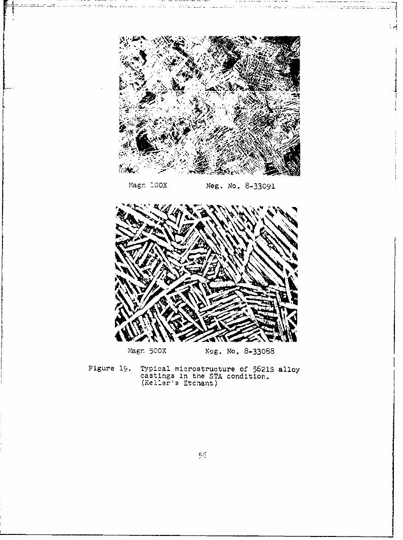
The remainder of metallograpnic studies on tne variousalloys and castings showed a wide range of structuresand grain sizes. Typical annealed structures ofTi-6Ai-4V alloy representing each casting process areshown in Figure 17. The remaining photomicrographsare included to show the wide structural differencesof solution treated and aged Ti-6A1-4V (Figure 18),5621S (Figure 19), IM1700 (Figure 20) and Beta III(Figure 21). There were essentially no differencesin structure noted, except for grain size, betweenheavy and thin sections cast by a given process, orbetween castings produced by induction and skullmelting. Thin test sections were normally finegrained and thick test sections were generally coarser.The grain size determination was conducted by comparinga specimen at 10 diameters with plate 1 of ASTM El/2which relates to examination at 100 diameters.Table XIII lists the observed ranges.
:I '

7--W
Mapgri looX Neg. No. 8-29564
Magn 5OOX Neg. No. 8-29561
Figure 15. Typical as cast surface of Ti-6A1-4V alloythin test section cast by the inductionmielting process. (Ni Plated -Keller's Etcharit)
52

.~.7*
Mag loX e. O.8296
Alph Stblie
Magn~ 5iOX Neg. No. 8-295623
ST codiin. (Klerscthat

IVI1-A-
ku1 melt Nag. No. 8-30638
FiL ~atfcu'r<p I . e canald (3512hs
Ti6I4 v catns KllrsEcat

... •.. .. .:., . ,.< .. ,, 1 #e' •',; .•%
. , .- '~ . . ,>;V•
1,4r
Mgn 0OX-. No. 8-33070
Magn 5C0X Neg. No. 8-33072
Figure 18. Typical microstrdcture of TI-6Al-4V alloycastings in the STA condition. (Keller'sEtchant)
N-1
INA, .11
Man 0.jXg. No -38
Figure 19. Typical microstructure of 5621S alloycastings In the STA condition.(Keller's Etchant)

7A'
.44
1'o
M~agn 5.OOX Neg. No. 8-33089
Figure 20. Typical m~icrostructure of IMI700 alloycastings in the Si'A condition.(Keller's Etchant)

4.44
v~
IMagn 10OX Neg. No. 8-33082
Niagn 5-=OX Neg. No. 8-33079
Figure 21. Typical microstructure of Beta III alloycastings In the STA condition. (KrollsZtchanD)
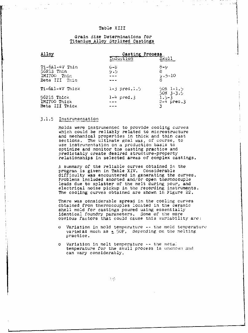
Table XIII
Grain Size Determinations forTitanium Alloy Stylized Castings
Al.lo Casting P'OCesaIniuuion Skull
Ti-6A!-4V Thin 6-6-5621S Thin 9.5 8IMI700 Thin --- 9.5-10Beta III Thin --- 8
Ti-6AI-4V Thick 1-3 pred.l.5 50% 1-1.550% 3-3.5
56213 Thick 1-4 pred.3 1.5-3IM1700 Thick --- 2-4 pred.3Beta III ThicK --- 3
3.1.5 Instrumentation
Molds were instrumented to provide cooling curveswhich could be reliably related to microstructureand mechanical properties in thick and thin castsections. The ultimate goal was, of course, touse instrumentation on a production basis tooptimize and monitor the casting practice andpredictably create desired structure-propertyrelationships in selected areas of complex castings.
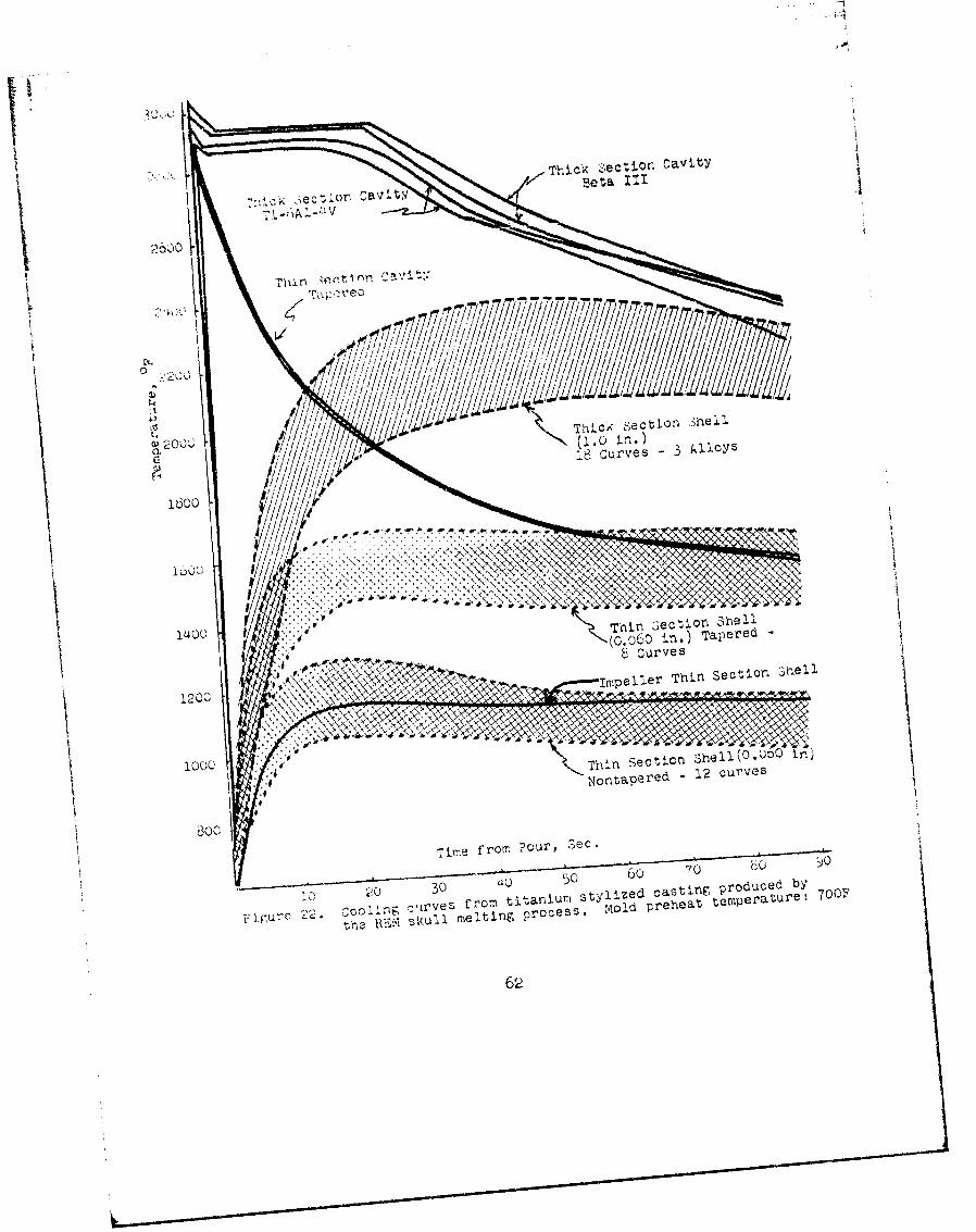
A summary of the reliable curves obtained in theprogram is given in Table XIV. Considerabledifficulty was encountered in generating the curves.Problems included shorted and/or open thermocoupleleads due to splatter of the melt during pour, andelectrical noise pickup in the recording instruments.The cooling curves obtained are shown in Figure 22.
There was considerable spread in the cooling curvesobtained from thermocouples located in the ceramicshell mold for castings poured using essentiallyidentical foundry parameters. Some of the moreobvious factors that could cause this variability are:
o Variation in mold temperature -- the mold temperaturevariedas much as *_ 5OF, depending on the meltingpractice.
o Variation in melt temperature -- the metaltemperature for the skull process is unknown andcan vary considerably.

Table XIV
Summary of' Cooling Curves Obtained FromInstrumentation of Titanium Stylized Castings
Cooling CurvesiCasting Pour •",h4.n s-e c tion Thikeeo'6process Alloy No. Cavity -Sh--el C-aity Shell
Inauction Ti-6Al-4V 1 a c a a(nontapered) 2 a yes a c
3 a a a c4 yes yes c c5 c yes c c6 yes a a a7 yes yes a c8 yes a a c9 a yes b a
10 yes b b c
5621S 1 a yes a yes2 a c yes yes3 c c a c4 a yes yes c
Skull Ti-6AI-4V 1 b c b yes(nontapered) 2 b yes b yes
3 b yes b y4 b yes b yes5 b c b c6 b c b yes7 b yes b yes8 b c b c9 b yes b c
56213 1 b yes b yes2 b yes b yes3 b c b yes4 b yes b c5 b yes b yes
IMI700 1 b c b yes2 b yes b yes3 b yes b c4 b yes b yes
6o
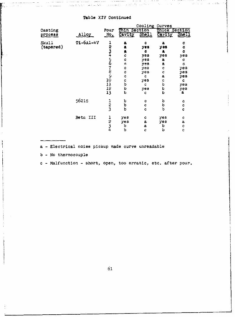
Table XIV Continued
Cooling CurvesCasting Pour Thin Section Thick Sectionprocess Alloy No. aCavi' Shel
Skull Ti-6A1-4V I a c a c(tapered) 2 a yes yes c
a, a cSc yes yes yes
5 c yes a c7 c yes c yes
8 c yes c yes9 c c a yes
10 c yes c c11 b c b yes12 b yes b yes13 b c b a
5621S I b c b2 b c b c3 b c b c
Beta Ill 1 yes c yes c2 yes a yes a3 b a b c4 b c b C
a - Electrical noise pickup made curve unreadable
b - No thermocouple
c - Malfunction - short, open, too erratic, etc. after pour.
61
ET44
ThI
Thin 3ectlOl -,hell1400(0.060 in. ) Tapered
120C Ilypeller Thin Section shell
: f 4Nontapered - 12 curves
Time from POuV, Sec.
5 60 70
20 30 ylzdcsig0P~ueýb
,r e f roll m ti 'a n'prO lSS Io d preheat tempera ture : 700F
62

" Accuracy in positioning thermocouple --
any variation in the thickness of the firsttwo shell dips would result in a variationof the couple position.
"o Total shell thickness -- inherent variationg inmo..ld t.h. rGS t1at ucuu, in non-automated moldfabrication influence the cooling characteristicsof the mold.
In addition, there was no correlation between themold cooling curvcvE for' the thicx and tnin sections,i.e., a curve falling in the upper portion of thethick section range did not necessarily correspondto a curve falling in the upper portion of the thinsection range. This was also true for correspondingcavity and mold curves. In fact., there appeared tobe as much variation between the curves for acasting as there was between shell mold curves fordifferent castings.
The cavity curves were more consistent than the moldcurves, i.e., less spread. This is understandablesince some of the factors accounting for the variabilityin the shell mold curves are less influencial oncavity curves. The initial transient temperature ofthe cavity, during the first few seconds after pour,were not reflected In the mold curves due to theinherently lower location related sensitivity ofthe shell mold thermocouples. However, it isquestionable whether the shape of the cavity curve inthese first few seconds bears any practically usefulrelationship to the structure or properties of thecasting.
There appeared to be no correlation between the moldtemperature curves (thick section vs thin section)and the basic microstructure or tensile properties.The only obvious correlation was with the macro grainsize. As expected, the higher temperature curves forthe thick sections correlate with the larger grainsizes in those sections.
Because of the aforementioned variations and lack ofpositive correlations the coou..•g curve data werenot submitted for mathematical analysis.
In summary, it does not appear that mold instrumentationis a useful tool for monitoring the casting practice orpredictably creating specific structure-propertyrelationships in titanium alloy castings.

II
3.2 ?'HA,. ii OO'TrMUM ALLOY EVALUATION
3.2.I Alloy oelection
A !•V'L,2 o(I' I tensile data indicated that cast
T' - WAI-4V diloy (,-TA) offered the best combination:ýcnnio••tent wn needs of high speed
-.,A tIt ii, comorients, e.g., an impeller, over the,Utiic.'ILtr02i oj,,;!r,,zg temperature range for suchF counpunuiits. IDITQO and Beta III castings exhibitedI lnsuflclent ductility, while 56213 alloy wasdf I..2Ilnt in strength. In addition, Ti-6AI-4V alloycasLLri,ý: xhlibLted distinctly superior high cyclefatigue characteristics. Thus, Ti-6AI-4V alloy waschosen fov Phase II evaluation.
3.2.2 Low Cycle Fatigue Tests - Stylized Castings
ISotnermnal fully reversed strain controlled low cycleVattgue (LCF) tests were performed at room temperatureand 70OF on specimens taken from the thick sectionsof ten (.10) stylized castings. The cata are reportedas strain range ver'sus cycles to failure for axially].oaded specimens. Cracx initiation lives are alsoincluded. Both elastic and plastic strain valuesfollowed curvilinear paths. A comparison of totalstrain range vs cycles to failure for cast Ti-6Al-4VSSTA) at room temperature, 70OF and wrought Ti-6A1-4VSTA) at 70OF is shown in Figure 23 and cyclic life
values are given in Table XV. The cast and wroughtLCF lives at 70OF are essentially the same for strainranges less than 1.0%. Cast titanium room temperatureLCF lives are'cast titanium LCF 700F lives below3000 cycles (Act = 1.3%) and> cast Ti 70OF livesabove 3000 cycles. This behavioral change can beattributed to lower plastic strain resistance of castTI at room temperature for short lives (/ 3000 cycles)and its higher elastic strain resistance at longerlives (> 3000 cycles).
The summary of low cycle fatigue results, Table XVIlists cycles to failure and crack initiation, stressranges and elastic, plastic and total strain valuesfor all tests conducted. The strain-life plots areshown in Figures 24 and 25.

a 24 5 67891 2 4 5607091 2 34 56 7891 2 2
II
Cast 70.OF *~ :..~: ,
cast and wrought Ti-6A1-4v (STA)
Table XV
Comparison of Strain Range to Cycles forCast and. Wrought T1-6A1-4V (STA)
C les to FailureStrain Range, % Cast Cast 70OF Wrought 700F
3.0 2625I92.0 400 845 16501.5 1600 1820 28501.0 8400 5300 55000.9 13500 8000 8300
65

Table XVI
-ummaI'y of Low Cycle Fati ue Results-- For Cast Ti-6Aa-4VJ(STA)
__Room T'emperature LIU rpmE-aTIstic Cycic Valu-e*
Cyclees so CyCle S StrPsEA StrainRange,P2. Crac to Failure Range E*-Tastic Plastle TotaTNo DI_9_ I* t iatlor) Nf 2,), ,xsi i~ ih A]•h_
24 326.3 1.954 1.219 3.173.. 1 (U 103 295.0 1.770 0.750 2.5202 31( 561 274.3 1.643 0.362 2.OC.-1413 1531 231.0 1.380 0.144 1.5243-, .... 4394 184.4 1.104 0.089 1.193u-n 3)34 u657 173.5 1.040 0.030 1 .070Io-i 14z48., 16149 149.o 0.890 0.007 0.897
700F 5 cpm
-I iNý 40 220.8 1.566 3.493 5.0k-1 72 112 219.0 1.553 2.335 3.8•$Lb3-1 162 226 191.2 1.356 1.723 3.07w
50-2 627 180.2 1.278 0.857 2.135i085 1339 158.7 1.126 0.507 1.633
8-2 2705 3227 148.0 1.050 0.173 1.2236-2 5609 6002 126.3 o.896 0.071 o.9671-1 11893 12873 118.0 0.836 0.006 0.842
* Approximate nalf-life values
(1) Values taken for a 100 pound load drop

-- - - - - -- - -MILE
mo
4-)
07iIm.......

if ITPCJ
...... 'J Ill 13 I M N Iij,4 L 11444
510 0 0
~5NU~J I~.all.8 ..... 1...

3.2.3 Tensile Tests- Impeller CastinEThe cast impeller used for tensile propertyevaluation is shown in Figure •6. Thq gating wasremov•d - .. h tr-trrt~t. After solutiontreating and aging, the casting was further sectionedto provide speciments for, tensile tPsts. The onlyarea suitable ror specimrens was the base plate. Toprovide a more accurate deter-minar.ton of strength,five flat cnordal specimen!o (iuoclzt,) anra , flatradial specimens were made, alter'nating the locationto thus provide I radial, I chovcdal, utc., Li shownin Figure 27. Results of' tv.ting are giver inTable XVI1. The eata indicate that full solutioningand subsequent aging may not have aeen achievedthroughout the casting due to tne mass of materialwhich prevented a rapid quench. Yield strength(O.2ýi offset) approacihed the ultimate tensile strengths.Elongations were quIte low averaging only 4-', a figureapproximating elongations of thin test sectionspecimens from stylized castings. The chordalelongations are higher due in part to measurementover a 0.6 in. length instead of the ustal 1 in.The chordal specimens do show th1at tne quencn wasmore thorough near the impeller circumference dueto the smaller mass in that area. It had beenintended to generate specimens from the shaft areabut examination of a 2-inch. diameter section showeda void which precluded specimen preparation.Radiographic examination of the tensile specimensshowed only weak sporadic indications, none of whichwas associated with the tensile fractures. Chordalspecimen strength data showed good correlation withdata from the heavy sections of stylized specimens,i.e., 156 ksi ultimate strength for the impellervs 155 ksi for the stylized casting.
3.2.4 Metallographic Evaluation - Impeller Casting
Basic microstructure of the impeller casting (STA)were essentially identical to those observed i-"stylized castings (STA) with respect to grainboundry and matrix characteristics. Grain si;:..e wasrated in the same manner as described in I'base 1,paragraph 3.1. Grain size in the base plate ar-.a,from which chordal tensile specimens were Fen,.-lated,was approximately '.-,-'f.r -> as compared to 1-3 :tciUfor the thick and thin sections of the s3y.lize,1castings.
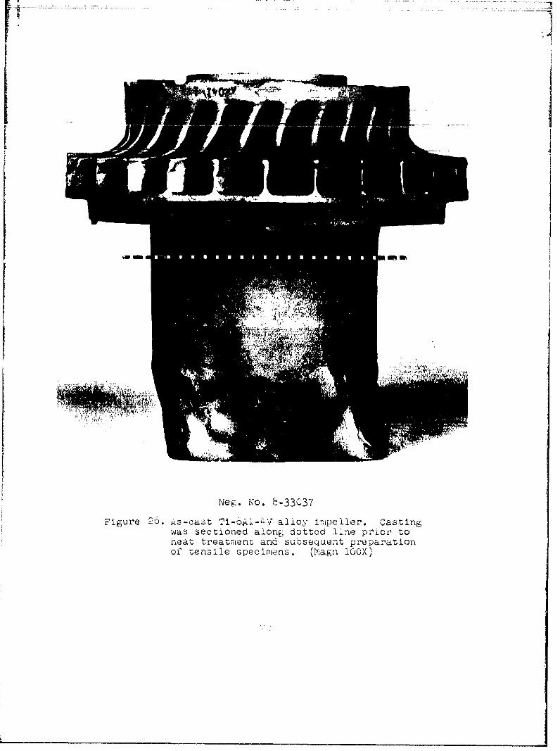
Fiur Ascs Ik-' lo melr atn
neattretmet an suseqentpreparation

R---Radial (3 in. length)
Me ta11oV ra phy- r,j;/ Chordal (;'.P In./ lengtii)
Figure 2Y. Sketch snowing location of' tensile andmetallographic specmoens From Ti-bAi-4V
,<ull melt impeller castin.
3.2.5 Spin Testing
One Impulleer !r:ar i;pn was p,roc u rd i'P, ucpn teusting.Fluorescent penetrant inspection FlIl) of the casting,in the as receLved condition, revealed cracks in severalairfoils, some of which were through cracks as long as0.5 in. In addition, several small cracks were noted Inthe surface of the hub between the roots of airfoils.Typical FPI indicatlons are shown in Figures 28 and 29.A few of' the airfoil cracks Increased in length duringsubsequent solution treatment but no growth occurredduring aging.
Visual examination r-evealed some minor surface pittingon the outside diameter of' the hub between the airfolls.This condition probably was a result of micrc--razlng ofthe tungsten face coating of the shell mold related todisparity In the curing cycle of ceramic shell materialin these extremely t...ght blind recesses.
Prior to heat treatment, a Iarv'e portton of the heavygating was removed to Insurie an adeq<iate quenchiing rvtIIn the hub area. Tht, east1ng was- sulut!on ir,'ated Li17POF - I hir (Argon) + H.A) quench and apged at, [OOF -
h rr- (Alr + A,,C.
This im1 ,ei1er was cast f'tom a d1l'fe,•rnt heat oC nai•,.r'aithan had oeen used to produtce thU . styI'.ed 7 CLJ . rig ,i .flrzst .impeller casting tiiat was used to g•i,,nvatedt mnc"' hact 1propt.rty data. The ca t lng rsuppl..ie.-' gligge.-tt,id t, hal a lower,solution tempe 'a tu r, mIg-ht have buor-, bertet' , a I from tI.!Ifract.iire toug, iri.•sss tu'nJ *e n .
t']'

Table XVII
woorn Temperature Tensile Properties of SpecimensGenerated from Ti-6Al-4V ImpellerCast by the Skull Melting Frocesa
Mod U 1 J 8UT_., ''. 2. YS, Elongation, of ElpsticityLocat Loll , kI t 1iO psi Note
h adal .a, 1 140.5 2.2 15.8 Elongation'adi•a 1:.4 , 145.8 5.0 13.8 Measured in/in
4tadla1 1!4. t 140.5 5.3 Not measured1a.i-d T'7.4 146.7 3.5 Not measured
iiadial 144.0 13I.0 4.2 Not measuredAvg. 140.1 1i40. 4.0---.
Cnordal 1i:7.3 --- 13.1 Not measured ElongationChordal IP1.9 i146.3 9.8 Not measured Measured in
0.6 in.Chordal l1'o.u 1')5.0 8.0 Not measuredChordal 1>3.0 144.0 8.1 15.9Chordal l6i.0 151.0 11.3 i.6.0
Avg. i:,58 14s.1 10.0 15.9
Heat Treatment:
Solution: 1750F-I hr in argon - H2 0 quenchAge: l00OF-4 hrs - air cool
Si 7.¸ 7 7 17 7 .:i.7 7 31 '17'1 1
Preliminary evaluation of the deflciencies noted In thecasting suggested that the condition of the impeller wasmarginal relative to spln testing, However, It wasconsidered appropriate to conduct the spin test asprogrammed. The appearance of the impeller as finishmachined for spin testflnw iR mh~wn In 0....
The impeller was o pin t sted at room temperature. Thepro. . .dure .on.i:tcd.. , a ,rui at TO,,"C0 rpm fO,' 0.. mrinand then Increasln. r .fi :.ipeed jr) irt remerj ts of 0,000 rpm,holdine for U.1, i7-n i±t each step. F.a' lure orcurred at50,000 rpm in the alr't'olls. An oV,'dll Vlew vie thufailed impelier is ihown in ,1gue',i. The exact orl)kinof failure co-ld not be determined. !iowever', tne fallurepath included portions of at least two pre-ex'sting cracks,one of which was a through crackr approximately 1.() Inlong, as evidenced by the heat tinted curf'ace shown InFigure i2. The aforemuntloned deflciencies in the outsidediameter surface of the hub were, not involved in thefaliure. The failure rpm was only half of the predictedburst rpm.
It was predicted that. burst of' this Impeller would occurnear 10i,0OO rpm. Thi,-n predlet. on was based on thefollowing criteria:
"o Blades and hub were to print.
"o Elongation was in excess of 51.
"o There were no flaws of critical size such that. fracturetoughness became the basis on which to predict ourst.
"o Failure would be based on ultimatc strength.
The calculations utilized the following mechanical propertieswhich were determined earlier in the program.
Ultimate strength - 150,000 psiElongation - 6%Density - 0.160 ibs per cu in
The prediction was based on calculations that utllzcdpre-existing data obtained f'rom steel Impellers of thisame configuration, rnaiinw the necessary adju:.,-ments fordensity differences. Utilizatlon factors (averagetangential stress/ultimate tensile stress) of 0o7.' and i.,were employed In the iiub and alrfoll stress analyse,,;respectively. Because of thte difference In !t;',lza lfionfactors the predicted burst speeds based on 0ot."i tlt, hut'and airfoil analyses, were es.1entlally thc namc.

1i wa.- •(culatecd that, at failure, the average tangential
t, re• ot' the nub reached 25,000 psi with maximum stressesas higr, ac 70,000 psi at the bore. The airfoil experiencedmaximum otresoer of approximately 32.000 psi. It was,tierefore, concluded that the defects in the airfoil wereor' such a magnitude that the structure was unable to
realIze Its inherent ultimate strength capability.
it sir, ,cn.ile tests were conducted on chordal specimens4-) 1'"n,- the web o' -he Impeller, as illuetrated in
Figvul-',.". Phe averaFe i-esults are as follows:
Ul.tlmnate strent:th - 160,000 psi0.,-1 Yield strength - 155,000 psiElongation in L inch - 4.0%
Tie ctoiengths are siLghtly higher and the elongations li-n'Iy lower than determined earlier in the program.Phes.e differences in data suggest slightly lower fracturetoulhneýs3 tnan anticipated prior to spin testing. This'od t1ion sImply amplifLes the influence of the afore-.entionet, airfoil detects.
It appears 'that the state of the titanium casting art inexistence at the time the impeller was cast was notadequate to ,'oduce ar unusually complicated impeller shapecapabile of demonstrating full realization of its mechanicalpropert'ies in a high speed rotating application. However,the casting supplier has manufactured somewhat simplerimpeller shapes which have performed satisfactorily Inhigh speed rotating applications.
74

Magn 2/3 X Neg. No. 8-33429
Figure 28. Ti-6AI-4V cast impeller showingFPI indications.

P-atin IX NeE,. o. 8-33428
PF'Iuve 2). Ti-uA1-,O/ casit Imp~elleýr T;howing FEC,ndicaticns n airfoils.

I7
YMagri 2/3X Neg. No. 8-33493
Figure 30. Ti-6AJ.-41 cast Impeller finishmachined for spin test:ing; castby REM Metals Corp.
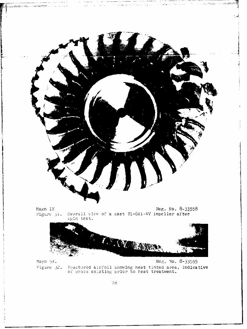
Magn IX Neg. No. 8-33558{'igurc ý-i. Overall. v.Iew,, of' a cast Ti--6A1-4V impeller after
w-in test.
L EL
Magn IX Neg. No. 8-33555-igure 3c tuartured airfoil showing heat tinted area, indicative
or criack existing prior to heat treatment.
76

SECTION IV
CONCLUSIONS AND RECOMMENDATIONS
There is no apparent need to develop new titanium alloysfor the purpose of producing complex cast shapeps
The castability of Ti-6Al-4V, 5621S, IMI700 and Beta IIIalloys is essentially the same and is sufficient topermit casting of complex shapes with high aspect ratiothin sections.
A slight taper of 1-3 degrees is required to achieve highlevels of internal soundness, e.g., ASTM E192, Grade 3 orbetter, in thin cast titanium sections, e.g., 0.060-0.o80 in.,with aspect ratios of - -20:1.
Contamination of cast titanium surfaces related to moldreaction can be avoided by use of refractory metal facecoated ceramic shell molds.
The skull melting process is more amenable than the bottompour induction melting process to production of complextitanium alloy castings with high aspect ratio thin sectionswhich require high levels of internal soundness.
Induction melting has considerable promise as a means forproducing titanium castings of relatively simplerconfigurations than those involved in this program.
Of the cast alloys investigated, i'i-6A1-4V offers acombination of mechanical properties compatible withrequirements cited by designers of advanced gas turbineengine rotating components such as a compressor impeller.
Instrumentation of ceramic shell molds to recordsolidification and subsequent cooling curves is not auseful tool for optimizing or monitoving titanium alloycasting practices.
Castings of Ti-6Al-4V, 56215 and Beta III alloys haveexcellent resistance to damage from impact by high velocityforeign objects. IM1700 alloy is relatively susceptible toballistic impact damage.
79

-Unlaxial tensile ultimate and O:-P•5&•i•ed--y trengthsof -ap;.rop:latoiy hedt treated Ti-6Al-4V, 5o2lS, IMI700 and9eta 111 alloy castings are essentially equal in heavyand thin 3ection-s and to stienrtgh exhibited by thesealloys in wrought form. Tensile ductility is somewhatlower in the cast form.
700F cast and wrought LCF lives for Ti-6A1-4V alloy areussentiaild,, the same for strain ranges less than 10;.No room temperature wrought data were available forcomparison.
The 5 x lO cycle endurance limit of cast Ti-6A1-4V alloyis comparable to that of the alloy in wrought form. Theendurance limit to ultimate tensile strength ratio forcast 5621S and Beta III alloys is considerably less thanexhibited by cast Ti-6AI-4V.
Additional studies should be conducted to determine whethermechanical properties of titanium alloy castings can beenhanced through the use of unique thermal treatments.
Induction melting should be furthlr evaluated to determinethe range of applications and econumic advantages whichcould be derived from this casting method.
The state of the titanium casting art in existence at thetime the unusually complicated impeiler shape evaluated inthis program was cast was not adeqtate to produce an impellercapable of demonstrating full realization of its mechanicalproperties in a high speed rotating application.
80